EP1248573B1 - Device for securing spinal rods - Google Patents
Device for securing spinal rods Download PDFInfo
- Publication number
- EP1248573B1 EP1248573B1 EP00923103A EP00923103A EP1248573B1 EP 1248573 B1 EP1248573 B1 EP 1248573B1 EP 00923103 A EP00923103 A EP 00923103A EP 00923103 A EP00923103 A EP 00923103A EP 1248573 B1 EP1248573 B1 EP 1248573B1
- Authority
- EP
- European Patent Office
- Prior art keywords
- locking cap
- head portion
- spinal rod
- engagement
- relative
- Prior art date
- Legal status (The legal status is an assumption and is not a legal conclusion. Google has not performed a legal analysis and makes no representation as to the accuracy of the status listed.)
- Expired - Lifetime
Links
Images


Classifications
-
- A—HUMAN NECESSITIES
- A61—MEDICAL OR VETERINARY SCIENCE; HYGIENE
- A61B—DIAGNOSIS; SURGERY; IDENTIFICATION
- A61B17/00—Surgical instruments, devices or methods, e.g. tourniquets
- A61B17/56—Surgical instruments or methods for treatment of bones or joints; Devices specially adapted therefor
- A61B17/58—Surgical instruments or methods for treatment of bones or joints; Devices specially adapted therefor for osteosynthesis, e.g. bone plates, screws, setting implements or the like
- A61B17/68—Internal fixation devices, including fasteners and spinal fixators, even if a part thereof projects from the skin
- A61B17/70—Spinal positioners or stabilisers ; Bone stabilisers comprising fluid filler in an implant
- A61B17/7001—Screws or hooks combined with longitudinal elements which do not contact vertebrae
- A61B17/7035—Screws or hooks, wherein a rod-clamping part and a bone-anchoring part can pivot relative to each other
- A61B17/7037—Screws or hooks, wherein a rod-clamping part and a bone-anchoring part can pivot relative to each other wherein pivoting is blocked when the rod is clamped
-
- A—HUMAN NECESSITIES
- A61—MEDICAL OR VETERINARY SCIENCE; HYGIENE
- A61B—DIAGNOSIS; SURGERY; IDENTIFICATION
- A61B17/00—Surgical instruments, devices or methods, e.g. tourniquets
- A61B17/56—Surgical instruments or methods for treatment of bones or joints; Devices specially adapted therefor
- A61B17/58—Surgical instruments or methods for treatment of bones or joints; Devices specially adapted therefor for osteosynthesis, e.g. bone plates, screws, setting implements or the like
- A61B17/68—Internal fixation devices, including fasteners and spinal fixators, even if a part thereof projects from the skin
- A61B17/70—Spinal positioners or stabilisers ; Bone stabilisers comprising fluid filler in an implant
- A61B17/7001—Screws or hooks combined with longitudinal elements which do not contact vertebrae
- A61B17/7032—Screws or hooks with U-shaped head or back through which longitudinal rods pass
-
- A—HUMAN NECESSITIES
- A61—MEDICAL OR VETERINARY SCIENCE; HYGIENE
- A61B—DIAGNOSIS; SURGERY; IDENTIFICATION
- A61B17/00—Surgical instruments, devices or methods, e.g. tourniquets
- A61B2017/00831—Material properties
- A61B2017/00858—Material properties high friction, non-slip
Landscapes
- Health & Medical Sciences (AREA)
- Orthopedic Medicine & Surgery (AREA)
- Life Sciences & Earth Sciences (AREA)
- Neurology (AREA)
- Surgery (AREA)
- Heart & Thoracic Surgery (AREA)
- Engineering & Computer Science (AREA)
- Biomedical Technology (AREA)
- Nuclear Medicine, Radiotherapy & Molecular Imaging (AREA)
- Medical Informatics (AREA)
- Molecular Biology (AREA)
- Animal Behavior & Ethology (AREA)
- General Health & Medical Sciences (AREA)
- Public Health (AREA)
- Veterinary Medicine (AREA)
- Surgical Instruments (AREA)
- Prostheses (AREA)
Description
- The subject disclosure relates to implantable spinal stabilization systems for surgical treatment of spinal disorders, and more particularly, to a device for connecting cylindrical spinal rods of a spinal stabilization system to the spine.
- The spinal column is a complex system of bones and connective tissue which protects critical elements of the nervous system. Despite these complexities, the spine is a highly flexible structure, capable of a high degree of curvature and twist through a wide range of motion. Trauma or developmental irregularities can result in spinal pathologies which limit this range of motion.
- For many years, orthopedic surgeons have attempted to correct spinal irregularities and restore stability to traumatized areas of the spine through immobilization. Over the past ten years, spinal implant systems have been developed to achieve immobilization. Examples of such systems are disclosed in U.S. Patent Nos. 5,102,412 and 5,181,917 to Rogozinski. Such systems often include spinal instrumentation having connective structures such as elongated rods which are placed on opposite sides of the portion of the spinal column intended to be immobilized. Screws and hooks are commonly utilized to facilitate segmental attachment of such connective structures to the posterior surfaces of the spinal laminae, through the pedicles, and into the vertebral bodies. These components provide the necessary stability both in tension and compression to achieve immobilization.
- Various fastening mechanisms have been provided in the prior art to facilitate securement of screws and hooks to the connective structures of a spinal stabilization system. For example, U.S. Patent No. 5,257,993 to Asher discloses an apparatus for use in retaining a spinal hook on an elongated spinal rod. The apparatus includes a body extending upwardly from a hook portion and having an open ended recess for receiving a spinal rod and an end cap engageable with the body to close the recess. A set screw is disposed in the center of the end cap to clamp the rod in the recess of the body. The end cap and body are interconnectable by different types of connectors including a bayonet connector, a linear cam connector or a threaded connector. Other examples of fastening mechanism for facilitating attachment of screws and hooks to the connective structures of a spinal stabilization system are disclosed in U.S. Patent No. 5,437,669 to Yuan et al. and U.S. Patent No. 5,437,670 to Sherman et al.
- In each of these prior art examples, threaded fasteners are used to facilitate securement of the connector to the spinal rod. Yet it is well known that threaded fasteners can become loosened under the influence of cyclically applied loads commonly encountered by the spinal column. Furthermore, during assembly, excessive torque applied to a threaded fastener can cause damage to the fastener as well as to the connective device with which it is associated.
- It would be beneficial to provide a more reliable and effective mechanism for facilitating the attachment of screws, hooks and clamps to the connective structures of a spinal stabilization system.
- WO 99/65415 discloses a device for securing spinal rods. Thereby a locking member has to be inserted in a securement body in direction of a rod. The locking member is secured in the securement body by retention ports and corresponding engagement tabs. However it is a drawback of this invention that the locking member has to be inserted in direction of the rod, this is inefficient regarding spatial design. A further disadvantage is that high forces are required to securely mount the locking member.
- The subject disclosure is directed to a device as specified in
Claim 1, for securing a spinal rod to a fixation device such as a pedicle screw or a lamina hook. The device disclosed herein includes a head portion configured to receive a spinal rod, a locking cap configured to engage the head portion and the spinal rod upon rotation of the locking cap relative to the head portion to secure the position of the head portion relative to the spinal rod, and a fastener portion extending from the head portion and configured to engage the spine. The fastener portion of the device can be in the form of a screw, hook or clamp, or any other configuration known in the art. - The head portion of the device has a channel extending therethrough for receiving a spinal rod and the channel is preferably bounded by opposed side walls each having an arcuate engagement slot defined therein. The locking cap preferably has opposed arcuate engagement flanges configured for reception in the opposed arcuate engagement slots of the head portion upon rotation of the locking cap relative to the head portion. Preferably, the opposed engagement slots are each defined in part by inclined slot surfaces, with the angle of the inclined surface of one engagement slot being opposite that of the opposed engagement slot. Similarly, the opposed engagement flanges are preferably each defined in part by inclined flange surfaces, with the angle of the inclined surface of one engagement flange being opposite that of the opposed engagement flange. The head portion also preferably includes structure for interacting with the locking cap to prevent the opposed side walls of the head portion from expanding radially outwardly when the arcuate flanges are engaged in the arcuate slots.
- Preferably, the locking cap of the device is configured for rotation between an initial position in which the arcuate engagement flanges are 90° out of phase with the arcuate engagement slots, an intermediate position in which the arcuate engagement flanges are 45° out of phase with the arcuate engagement slots, and a locked position in which the arcuate engagement flanges are in phase and intimately engaged with the arcuate engagement slots.
- In this regard, the bottom surface of the locking cap preferably includes a first recess oriented to accommodate a spinal rod when the locking cap is in an initial unlocked position, a second recesses which intersects the first recess at a first angle to accommodate a spinal rod when the locking cap is in an intermediate position, and a third recess which intersects the elongate recess at a second angle to accommodate a spinal rod when the locking cap is in a final locked position. In accordance with a preferred embodiment of the subject disclosure, the first recess is an elongate recess, the second recess is a transverse recess which intersects the elongate recess at a 45° angle, and the third recess is an orthogonal recess which intersects the elongate recess at a 90° angle.
- The subject disclosure is also directed to a device for securing a spinal rod to the spine which comprises a head portion having a channel extending therethrough configured to receive a spinal rod, a locking cap including a first portion configured to engage an interior surface of the head portion and a second portion configured to engage an exterior surface of spinal rod received by the channel to secure the position of the head portion relative to the spinal rod, and a fastener portion depending from the head portion and configured to engage the spine.
- Preferably, the locking cap is a two-piece structure which includes an upper portion configured to engage an interior surface of the head portion and a lower portion configured to engage an exterior surface of the spinal rod to secure the position of the head portion relative to the spinal rod upon rotation of the upper portion relative to the lower portion and the head portion. The upper portion of the locking cap includes a bottom surface having an axial reception bore defined therein and the lower portion of the locking cap includes an upper surface having an axial post extending therefrom configured to engage the axial reception bore in the bottom surface of the upper portion of the locking cap and facilitate the relative rotation of the two parts. The upper portion further includes opposed arcuate engagement flanges configured for cammed engagement in correspondingly configured opposed arcuate engagement slots formed in the opposed side walls of the head portion upon rotation of the upper portion relative to the lower portion. The lower portion further includes a bottom surface having an elongated hemi-cylindrical recess that is oriented to accommodate a spinal rod extending through the channel in the head portion.
- In accordance with one aspect of the subject disclosure, the fastener portion is formed monolithic with the head portion. In accordance with another aspect of the subject disclosure, the fastener portion is mounted for movement relative to the head portion. In this regard, the head portion defines a central axis oriented perpendicular to the spinal rod channel and the fastener portion is mounted for angular movement relative to the central axis of the head portion. More particularly, the fastener portion includes a generally spherical head and a threaded body which depends from the spherical head, and the head portion defines a seat to accommodate the spherical head and an aperture to accommodate the threaded body. In use, upon rotation of the upper portion of the locking cap relative to the lower portion of the locking cap into a locked position, the position of the head portion relative to the spinal rod and the position of the fastener relative to the head portion become fixed.
- These and other unique features of the device disclosed herein and the method of installing the same will become more readily apparent from the following
- So that those having ordinary skill in the art to which the disclosed apparatus appertains will more readily understand how to construct and use the same, reference may be had to the drawings wherein:
- Fig. 1 is a perspective view of an elongated spinal rod of a spinal stabilization system having attached thereto a bone screw and a bone hook constructed in accordance with a first embodiment of the subject disclosure;
- Fig. 2 is a perspective view of a locking cap which forms part of the bone screw and bone hook illustrated in Fig. 1, oriented in an inverted position for ease of illustration;
- Fig. 3 is a perspective view of the bone screw and locking cap of Fig. 1 separated from one another for ease of illustration;
- Fig. 4 is a cross-sectional view of the bone screw of the subject disclosure taken along line 4-4 of Fig. 1;
- Fig. 5 is a cross-sectional view of the locking cap taken along line 5-5 of Fig. 3;
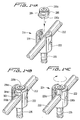
- Figs. 6A through 6D illustrate operative steps associated with attaching the bone fastener of the subject disclosure to a spinal rod, wherein:
- Fig. 6A illustrates the step of positioning the spinal rod and locking cap in the reception channel of the head portion of a fastening device of the subject disclosure;
- Fig. 6B illustrates the initial orientation of the locking cap relative to the head portion of a fastening device of the subject disclosure wherein the locking cap is in an unlocked position;
- Fig. 6C illustrates the rotation of the locking cap relative to the head portion of a fastening device of the subject disclosure to a partially locked position; and
- Fig. 6D illustrates the rotation of the locking cap relative to the head portion of a fastening device of the subject disclosure to a locked position;
- Fig. 7 is a perspective view of a fastening device constructed in accordance with a second embodiment of the subject disclosure;
- Fig. 8 is a perspective view of the fastening device of Fig. 7 with the locking cap separated for ease of illustration;
- Fig. 9 is a perspective view of the locking cap of the fastener device of Fig. 7, oriented in an inverted position for ease of illustration;
- Fig. 10 is a cross-sectional view of the fastening device of Fig. 7 taken along line 10-10 of Fig. 7;
- Fig. 11 is a perspective view of an elongated spinal rod of a spinal stabilization system having attached thereto another version of a bone screw and another version of a bone hook constructed in accordance with another embodiment of the subject disclosure;
- Fig. 12A is an exploded perspective view of the bone screw of Fig. 11 with parts separated for ease of illustration including the two-piece locking cap and multi-axial fastener portion associated therewith;
- Fig. 12B is a perspective view, looking upward from below, of the two-piece locking cap of the subject disclosure illustrating the bottom surface features of the component parts thereof;
- Fig. 13 is a cross-sectional view of the bone screw of Fig. 11 taken along line 13-13 of Fig. 11 with the two-piece locking cap in a locked position;
- Fig. 14A through 14C illustrate, in counter-clockwise progression, the operative steps associated with attaching the bone screw of Fig. 11 to a spinal rod by employing the two-piece locking cap of the subject disclosure, wherein:
- Fig. 14A illustrates the step of positioning the locking cap within the head portion of the bone screw;
- Fig. 14B illustrates the initial unlocked orientation of the upper portion of the locking cap within the head portion of the bone screw; and
- 14C illustrates the step of rotating the upper portion of the locking cap relative to the lower portion of the locking cap and the head portion of the bone screw into a locked position to secure the position of the bone screw with respect to the spinal rod;
- Fig. 15 is an exploded perspective view of the bone hook of Fig. 11 with parts separated for ease of illustration including the two-piece locking cap associated therewith; and
- Fig. 16 is a cross-sectional view of the bone hook of Fig. 11 taken along line 16-16 of Fig. 11 with the two-piece locking cap in a locked position.
- These and other features of the apparatus disclosed herein will become more readily apparent to those having ordinary skill in the art from the following detailed description of the preferred embodiments taken in conjunction with the drawings.
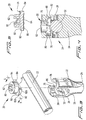
- Referring now to the drawings wherein like reference numerals identify similar structural elements of the subject apparatus, there is illustrated in Fig. 1 a section of a spinal stabilization system constructed in accordance with a preferred embodiment of the subject disclosure and designated generally by
reference numeral 10. - Referring to Fig. 1,
spinal stabilization system 10 includes an elongatedspinal rod 12 having a circular cross-section and a substantially smooth outer surface finish. As illustrated, fastening devices in the form of abone screw 14 and right-angle hook 16 are provided for securingspinal rod 12 to the spine during a spinal stabilization procedure. Both fastening devices employ a novel top-loaded locking cap, designated generally byreference numeral 20, which will be described in greater detail hereinbelow with reference to Fig. 2. The novel locking cap achieves significant clinical advantages over the prior art through its reliability and the ease in which it is installed during a spinal stabilization procedure. - It should be recognized that the subject disclosure is not limited in any way to the illustrated bone screw and right-angle hook. Rather, these particular fasteners are merely examples of the type of devices that can employ the novel locking cap disclosed herein. Other fasteners commonly utilized in spinal stabilization systems, such as, for example, hooks having alternative angular geometries as well as clamps are also envisioned. Indeed, it is envisioned that any component designed for attachment to an elongated spinal rod or transverse coupling rod, may incorporate the novel locking cap of the subject disclosure. Also, any number of fastening devices can be applied along the length of the spinal rod.
- With continuing reference to Fig. 1,
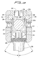
bone screw 14 includes ahead portion 22 defining a horizontal axis and a vertical axis. Ashank portion 24 depends from the head portion and a threadedportion 26 having a helical thread extending about the outer periphery depends from the shank portion. The helical thread is particularly adapted to securely engage the vertebral bodies of the spine. Achannel 28 extends through thehead portion 22 along the horizontal axis thereof for receiving elongatedspinal rod 12. As best seen in Fig. 3,channel 28 is defined by the interior surfaces ofside walls lower surface 29 which extends therebetween. Lockingcap 20 is dimensioned and configured for reception and engagement in lockingchannel 28 to secure the position ofbone screw 14 with respect tospinal rod 12 during a spinal stabilization procedure. - Referring again to Fig. 1, right-
angle hook 16 includes ahead portion 42 defining a horizontal axis and a vertical axis. Ahook portion 46 depends from thehead portion 42 for securement to a vertebral body of the spine. Achannel 48 extends through thehead portion 22 along the horizontal axis thereof for receiving elongatedspinal rod 12.Channel 48 is defined by the interior surfaces ofopposed side walls cap 20 is dimensioned and configured for reception and engagement inchannel 48 to secure the position ofhook 16 with respect tospinal rod 12 during a spinal stabilization procedure. - Referring now to Fig. 2, there is illustrated locking
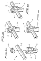
cap 20 in an inverted position to best illustrate structural aspects thereof. Lockingcap 20 includes acylindrical head 62 and aflanged portion 64. Thebottom surface 66 offlanged portion 64 includes anelongate recess 68 having a curvature complementary tospinal rod 12 for accommodating the spinal rod when lockingcap 20 is in an unlocked position, shown for example in Fig. 6B. In such a position, the fastening device may be moved freely along or rotated about the longitudinal axis of the spinal rod.Bottom surface 66 also includes a bifurcatedorthogonal recess 70 which intersects the elongate recess at a 90° angle and has a curvature complementary tospinal rod 12 to accommodate the spinal rod when lockingcap 20 is in a locked position, shown for example in Fig. 6D and Fig. 4. In addition,bottom surface 66 includes bifurcated first and secondtransverse recesses elongate recess 68 at opposite angles of intersection and have curvatures which are complementary tospinal rod 12 to accommodate the spinal rod when the lockingcap 20 is in either of two intermediate positions, one of which is shown for example in Fig. 6C. In such a position, the fastening device retains the spinal rod but is not fully secured, and if desired by the surgeon, lockingcap 20 can be rotated from the intermediate position and the fastener moved to an alternative location on the spinal rod. Preferably, the transverse recesses intersect the elongate recess at opposed 45° angles. However, those skilled in the art will readily appreciate that the transverse recess can be oriented at alternative intersecting angles. It is also contemplated that the bottom surface can be flat without any recesses. - Referring to Figs. 3 and 5, the
cylindrical head 62 of lockingcap 20 includes a hexagonal axial bore 80 extending partially therethrough for receiving a working implement such as a wrench to facilitate rotation of the lockingcap 20 relative to thehead portion 22 of the fastening device about the vertical axis defined thereby. It envisioned that alternative tooling configurations known in the art can also be utilized to facilitate axial rotation of lockingcap 20 during a surgical procedure.Curved notches walls cylindrical head 62 of lockingcap 20 when the locking cap is received and rotated withinchannel 28. - The
flanged portion 64 of lockingcap 20 is defined in part by two diametrically opposedarcuate engagement flanges arcuate engagement slots opposed side walls head portion 22. (See Fig. 4). - With continuing reference to Figs. 3 through 5,
engagement flanges camming surfaces - As best seen in Fig. 4, the
arcuate engagement slots head portion 22 offastener 14 have inclined surfaces which mate with the rampedcamming surfaces flanges camming surfaces arcuate engagement slots opposed side walls head portion 22 from spreading radially outward as the arcuate flanges are engaged with the arcuate slots when the lockingcap 20 is rotated to a locked position. - Figs 6A through 6D illustrate the steps in securing the fastening device to the spinal rod during a surgical procedure. Although attachment of a
bone screw 14 is shown, it should be understood, as noted above, that other fastening devices, e.g., bone hooks, can be secured to thespinal rod 12 using the locking cap and head portion structure of the present disclosure. Initially, as illustrated in Fig. 6A,spinal rod 12 is moved into approximation with thehorizontal channel 28 ofhead portion 22 such that the periphery of thespinal rod 12 is in registration with thecurved surface 29 of thechannel 28. Lockingcap 20 is then top loaded into the channel along the vertical axis of the fastener in the direction of arrow a. At such a time,spinal rod 12 is accommodated within theelongate recess 68 defmed in thebottom surface 66 of lockingcap 20 and thebone screw 14 may be moved freely relative to the spinal rod. The opposedflanged sections cap 20 are 90° out of phase from the opposedarcuate engagement slots head portion 22, as shown for example in Fig. 6B. - Thereafter, as shown in Fig. 6C, locking
cap 20 is rotated 45° relative to headportion 22 about the vertical axis thereof. At such a time,spinal rod 12 is accommodated within one of the twotransverse recesses cap 20 with respect to the head portion. Thereupon, the opposedarcuate engagement flanges cap 20 are only partially engaged with the opposedarcuate engagement slots head portion 22, as they are 45° out of phase with the slots. Consequently, the locking cap holds thefastener 22 andspinal rod 12 together, but does not lock the fastener. In this position, the lockingcap 20 can be readily rotated in the opposite direction to disengage from thespinal rod 12 to adjust the position of thebone screw 14 with respect to thespinal rod 12. - Once the desired position and orientation of the
bone screw 14 has been attained, lockingcap 20 is rotated another 45° to the locked position illustrated in Fig. 6D. At such a time,spinal rod 12 is accommodated within theorthogonal recess 70 defined in the bottom surface of lockingcap 20. Thereupon, the opposedengagement flanges flanged portion 64 are fully engaged with the opposedengagement slots head portion 22, and the longitudinal and angular orientations of thebone screw 14 are fixed with respect tospinal rod 12, as illustrated in Fig. 4. It should be readily apparent that the manner and method by whichbone screw 14 hook is attached tospinal rod 12 is identical to the manner and method by whichhook 16 or other fasteners are attached tospinal rod 12. - Since the rotational range of locking
cap 20 is limited, i.e., the locking cap can only be rotated 90°, it will be readily appreciated that the cap cannot be over-torqued. Thus, the damage often caused by over-tightening a conventional threaded locking mechanism, such as a set screw, is avoided. Furthermore, since the locking cap of the subject disclosure has a predetermined locked position, it is unlikely that it will be undertorqued or left in a loose condition after installation as is common with threaded set screws found in the prior art. That is, by having a predetermined locked position, uniform locking forces are provided for all of the fastening devices used to secure thespinal rod 12 along its length and cross threading is reduced. - Referring now to Figs. 7 and 8, there is illustrated another fastening device constructed in accordance with a preferred embodiment of the subject disclosure and designated generally by
reference numeral 110.Fastening device 110 is similar tofastening devices Fastening device 110 includes ahead portion 122 having opposedside walls horizontal channel 128 in conjunction with the curvedlower surface 129 extending therebetween.Arcuate tabs side walls cap 120. - Referring to Fig. 9, locking
cap 120, which is shown in an inverted position for ease of illustration, includes ahexagonal head 162, acylindrical body 163 and aflanged portion 164. Thehexagonal head 162 is adapted and configured for interaction with a wrench or similar work implement. Anannular channel 165 extends into the bottom surface ofhexagonal head 162 for receivingarcuate tabs opposed side walls head portion 122 from spreading radially outwardly whenarcuate flanges cap 120 are engaged inarcuate slots head portion 122 upon rotation of lockingcap 20 into a locked position. Thus, in this embodiment, the rampedcamming surfaces arcuate engagement flanges flanges cap 20 of the embodiment of Figs. 1-6. - With continuing reference to Fig. 9, the
bottom surface 166 of theflanged portion 164 of lockingcap 120 is configured in substantially the same manner as thebottom surface 66 of lockingcap 20 in that it is provided with anelongate recess 168 for accommodating a spinal rod when thelocking cap 120 is in an unlocked position, first and second bifurcatedtransverse recesses elongate recess 168 at opposite 45° angles to accommodate the spinal rod when thelocking cap 120 is in either of two intermediate positions, and a bifurcatedorthogonal recess 170 which intersects the elongate recess at a 90° angle to accommodate the spinal rod when thelocking cap 120 is in a final locked position, as shown in Fig. 10. It will be readily appreciated that lockingcap 120 is engaged withfastening device 110 in a manner that is substantially similar to the manner in which lockingcap 20 is engaged withbone fastener 14 andhook 16, and that the configuration of the bottom surface offlanged portion 164 provides the same benefits afforded by theflanged portion 64 of lockingcap 20. - Referring now to Fig. 11, there is illustrated two additional fastening devices constructed in accordance with the subject disclosure in the form of a
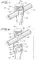
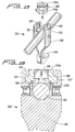
multi-axial bone screw 214 and a right-angle hook 216 which are provided for securingspinal rod 212 to the spine during a spinal stabilization procedure. Both fastening devices employ a novel top loaded two-piece locking cap, designated generally byreference numeral 220, which will be described in greater detail hereinbelow with referenced to Figs. 12 and 13. The novel two-piece locking cap achieves significant clinical advantages over the prior art through its reliability and the ease in which it is installed during a spinal stabilization procedure. As with respect to the previously described embodiments of Fig. 1, the novel two-piece locking cap may be used in conjunction with the other types of fasteners commonly employed in spinal stabilization procedures. Moreover, while the two-piece locking cap illustrated in Fig. 11 is employed with a multi-axial bone screw, it is readily apparent that the same two-piece locking cap could be employed with a fixed axis bone screw such as that which is illustrated in Fig. 1. - Referring to Figs. 12A and 13, the mulit-
axial bone screw 214 includes ahead portion 222 defining a horizontal axis "x" and a vertical axis "y". Achannel 228 extends through thehead portion 222 along the horizontal axis "x" for receiving an elongatedspinal rod 212.Channel 228 is defined by the interior surfaces of theside walls head portion 222.Bone screw 214 further includes afastener portion 224 which includes a generallyspherical head 225 and a threadedbody 226. Threadedbody 226 depends from and is monolithically formed with thespherical head 225. The threaded body includes a helical thread formation that is particularly adapted to securely engage the vertebral bodies of the spine. - The
head portion 222 ofmulti-axial bone screw 214 further defines a generally cylindricalvertical channel 227 which extends through and is aligned with the vertical axis "y" of thehead portion 222.Vertical channel 227 is configured to receive and accommodate thefastener portion 224 ofbone screw 214. More particularly, as best seen in Fig. 13, a lower interior surface portion ofvertical channel 227 defines anannular seating surface 229 configured to cooperate with the lower hemi-spherical region ofspherical head 225. The cooperative engagement between the two structures permits the relative movement of thefastener portion 224 with respect to thehead portion 222 about the vertical axis "y". The multi-axial motion afforded thereto, enhances the operational range ofbone screw 214, providing greater flexibility to the surgeon during a spinal stabilization procedure. -
Bone screw 214 further includes anannular retention ring 232 that is accommodated within a corresponding annular groove 234 formed within the cylindrical wall of vertical channel 227 (see Fig. 13).Retention ring 232 is adapted to positively engage thespherical head 225 and aiding in its stabilization. In addition, as best seen in Fig. 13, the lower hemi-spherical region ofhead 225 is scored with a series of circular ridges adapted to enhance the frictional coefficient of the seating surface defined thereby. - Referring to Fig. 12A,
bone screw 214 further includes a two-piece locking cap 220 which is dimensioned and configured for reception and engagement in thehorizontal channel 228 ofhead portion 220 to secure the position ofhead portion 222 with respect tospinal rod 212 during a spinal stabilization procedure. In addition, as described in detail hereinbelow with respect to Fig. 13, the securement of lockingcap 220 withinchannel 228 also achieves positive fixation of the angular position of thefastener portion 224 with respect to thehead portion 222 and the vertical axis "y" defined thereby. - As illustrated in Figs. 12A and 12B, locking
cap 220 includes anupper portion 220a and alower portion 220b. Theupper portion 220a includes acylindrical cap body 280 defining anaxial reception port 282 for receiving a tool or working implement that applies torque to the cap during installation.Upper portion 220a further includes a pair of circumferentially opposedarcuate engagement flanges cap body 280.Engagement flanges arcuate engagement slots opposed side walls flanges corresponding slots upper portion 220a of lockingcap 220 relative to thehead portion 222 ofbone screw 214. - The
lower portion 220b of lockingcap 220 is configured for cooperative reception within the cylindricalvertical channel 227 ofhead portion 222 and is adapted to engage thespinal rod 212 extending through thehorizontal channel 228 ofhead portion 222. More particularly, thebody 285 of thelower portion 220b had curved exterior surfaces which complement the curvature of the walls definingvertical channel 227. Thus, when thelocking cap 220 is loaded intovertical channel 227, a positive mating relationship is achieved between thelower portion 220b of thelocking cap 220 andvertical channel 227. As a result, the axial portion oflower portion 220b becomes fixed with respect tohead portion 222 andspinal rod 212. Furthermore, as best seen in Fig. 12B, a hemi-cylindrical channel 299 is formed in the undersurface oflower portion 220b for intimately cooperating with the cylindricalspinal rod 212 upon loading thelocking cap 220 invertical channel 227.Body portion 285 includes anextension flange 302 which aides in the alignment and positioning of thelower cap portion 220a with respect tospinal rod 212. - As best seen in Fig. 12B, the bottom surface of the
upper portion 220a of lockingcap 220 includes a recessedseating area 287 and an associated axial reception bore 288. The recessedseating area 287 is dimensioned and configured to accommodate the body of thelower portion 220b of lockingcap 220, while the reception bore 288 is dimensioned and configured to receive and engage anaxial post 298 which projects from theupper surface 295 of thelower portion 220b of lockingcap 220. More particularly, during assembly, when theaxial post 298 is received by the reception bore 288, the top end of the post is swaged (flared out) to join the two components together (see Fig. 13). The interaction of theaxial post 298 and axial reception bore 288 facilitates relative rotational movement of theupper portion 220a relative to thelower portion 220b when thelocking cap 220 is loaded into and locked in thehead portion 222 ofbone screw 214 during a spinal stabilization procedure. - As described in detail hereinbelow with reference to Figs. 14A-14C, the two-part locking cap enables a surgeon to load the
locking cap 220 intovertical channel 227 and properly position thelower portion 220b against thespinal rod 212 so as to ensure an intimate engagement between the hemi-cylindrical channel 299 and the cylindrical surface of the spinal rod. Thereafter, theupper portion 220a may be rotated into a locked portion relative to thelower portion 220b. - Referring now in detail to Figs. 14A-14C, during a spinal stabilization procedure, the
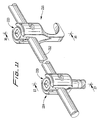
fastener portion 226 ofbone screw 214 is first seated within thehead portion 222. Then, thehead portion 222 is positioned at the surgical site in such a manner so that the elongatedspinal rod 212 extends through thehorizontal channel 228 as illustrated in Fig. 14A. Thereafter, if necessary, thefastener portion 226 may be moved into a desired angular orientation by the surgeon and subsequently mounted to the spinous process using suitable surgical instruments. - With reference to Fig. 14B, once the appropriate position of the
fastener portion 226 has been established by the surgeon, the lockingcap 220 is loaded into thevertical channel 227 ofhead portion 222 along the vertical axis "y" defined thereby. At such a time, the hemi-cylindrical channel 299 on the undersurfacelower portion 220b will become intimately engaged with the cylindrical surface of thespinal rod 212 and it will be maintained in a fixed axial orientation with respect to the spinal rod due to the mating relationship between the body of thelower portion 220b and thevertical channel 227. - Locking
cap 220 must be loaded in such a manner so that the radially outwardly extendingengagement flanges upper portion 220a are parallel to the axis ofspinal rod 212, as illustrated in Fig. 14B. Otherwise, the flanges will interfere with theopposed side walls head portion 222. Furthermore, care must be taken to ensure that theupper portion 220a of lockingcap 220 is positioned in such a manner so that the low sides of the flanges (e.g. 284a) are aligned with the high sides of the engagement channels (e.g. 294a), or the flanges will not cammingly engage the channels upon rotation of theupper portion 220a of thelocking cap 220 relative to thehead portion 222 ofbone screw 214. - Once the
upper portion 220a of lockingcap 220 has been properly oriented with respect tohead portion 222 with theextension flange 302 in alignment withspinal rod 212, it is rotated in a clockwise direction about the vertical axis "y" relative to thelower portion 220b of lockingcap 220 and thehead portion 222 ofbone screw 214 using an appropriate surgical implement or tool (not shown). Thereupon, thearcuate engagement flanges upper portion 220 cammingly engage thecorresponding engagement slots 284. Once rotated into a locked portion, thelower portion 220b of thelocking cap 220 will be seated within the recessedseating area 287 defined in thebottom surface 285 of theupper portion 220a of locking cap 220 (see Fig. 13). At such a time, the position of thehead portion 222 ofbone screw 214 is fixed with respect to longitudinal axis ofspinal rod 212 and the position of thefastener portion 226 ofbone screw 214 is fixed with respect to the vertical axis "y" defined byhead portion 222 ofbone screw 214, as illustrated in Fig. 14C. - Referring now to Figs. 15 and 16, the right-
angle hook 216 of the subject disclosure includes ahead portion 242 defining a horizontal axis "x" and a vertical axis "y". Ahook portion 246 depends from thehead portion 242 to facilitate securement of the device to a vertebral body of the spine. Achannel 248 extends through thehead portion 242 along the horizontal axis thereof for receiving elongatedspinal rod 212.Channel 248 is defined by the interior surfaces of opposedupstanding side walls Channel 248 is further configured to receive a two-piece locking cap 220 adapted to secure the position ofhook 216 with respect tospinal rod 212 during a spinal stabilization procedure. - As discussed hereinabove with respect to
multi-axial bone screw 214, the lockingcap 220 includes an upper anupper portion 220a and alower portion 220b which are rotatably joined together. The upper portion includes a pair of circumferntially opposedarcuate engagement slots opposed side walls head portion 242. As described in more herinabove with respect to Figs. 14A-14C, theflanges corresponding slots upper portion 220a of lockingcap 220 relative to thelower portion 220b of the locking cap and thehead portion 242 of right-angle hook 216. - Although the apparatus disclosed herein has been described with respect to preferred embodiments, it is apparent that modifications and changes can be made thereto without departing from the scope of the invention as defined by the claims.
Claims (17)
- A device (214, 216) for securing a spinal rod (212) to the spine comprising:- a head portion (222) having a channel (228) adapted to receive a spinal rod (212),- fastener portion (226, 246) depending from the head portion (222).- a locking cap (220) configured for reception by the head portion (222) and adapted to engage an exterior surface of the spinal rod (212) to secure the position of the head portion (222) relative to the spinal rod (212),characterized in that the locking cap (220) is rotatably configured for reception by the head portion (222) and adapted to engage an interior surface (294, 296) of the channel (228) and the exterior surface of the spinal rod (212) upon rotation of the locking cap (220) from an unlocked position to a locked position to secure said position of the head portion (222), the locking cap (220) having a first portion (220a) adapted to engage an interior surface (294, 296) of the head portion (222) and a second portion (220b) adapted to engage said exterior surface of the spinal rod (212), the first portion (220a) of the locking cap (220) being rotatable relative to the second portion (220b) of the locking cap (220).
- The device according to claim 1, wherein the second portion (220b) of the locking cap (220) has an elongated recess (299) configured to engage the exterior surface of the spinal rod (212).
- The device according to claim 1 or 2, wherein the position of the head portion (222) relative to the spinal rod (212) is secured upon rotation of the first portion of the locking cap relative to the second portion of the locking cap.
- The device according to one of claims 1 to 3, wherein the head portion has a central axis (y) and the first portion of the locking cap is rotatable about the central axis of the head portion (222).
- The device according to one of claims 1 to 4, wherein the locking cap (220) is rotatable about a central axis (y) between an unlocked position and a locked position, wherein the fastener portion (226) is movable relative to the head portion (220) when the locking cap (220) is in the unlocked position and the fastener portion 8226) is fixed relative to the head portion (222) when the locking cap (220) is in the locked position.
- The device according to one of claims 1 to 5, wherein the first portion and the second portion of the locking cap are coupled together by an axial post (298) that facilitates relative rotational movement of the first portion (220a) relative to the second portion (220b).
- The device according to one of claims 1 to 6, wherein the locking cap has opposed engagement flanges configured to cooperate with an interior surface of the channel and an exterior surface of the spinal rod upon rotation of the locking cap relative to the head portion between an unlocked position and a locked position to secure the position of the head portion relative to the spinal rod.
- The device according to one of claims 1 to 6, wherein channel (228) is bounded by opposed side walls (230, 232).
- The device according to claim 8, wherein each of the opposed side walls (230, 232) has an engagement slot (294, 296) defined therein.
- The device according to claim 9, wherein the locking cap (220) has opposed engagement flanges (284, 286) that are configured for reception in the opposed arcuate engagement slots (294, 296) of the head portion (222) upon rotation of the locking cap (220) relative to the head portion (222).
- The device according to claim 10, wherein the opposed engagement flanges are discontinuous.
- The device according to claim 10, wherein the opposed engagement flanges are arcuate.
- The device according to claim 10, wherein the locking cap is configured for rotation between an initial position in which the engagement flanges are not in contact with the engagement slots, an intermediate position in which the engagement flanges are partially in contact with the engagement slots and a locked position in which the engagement flanges are fully engaged with the engagement slots.
- The device according to claim 10, wherein the opposed engagement slots are each defined in part by inclined slot surfaces, with the angle of the inclined slot surface of one engagement slot being opposite that of the opposed engagement slot, and wherein the opposed engagement flanges are each defined in part by inclined flange surfaces, with the angle of the inclined flange surface of one engagement flange being opposite that of the opposed engagement flange.
- The device according to one of claims 1 to 14, wherein the fastener portion comprises a screw (226).
- The device according to one of claims 1 to 14, wherein the fastener portion comprises a hook (246).
- The device according to one of claims 1 to 16, wherein the channel (228) defines a vertical axis and a horizontal axis, and the spinal rod (212) is received along the horizontal axis.
Priority Applications (1)
| Application Number | Priority Date | Filing Date | Title |
|---|---|---|---|
| EP06017962.9A EP1723919B1 (en) | 2000-01-19 | 2000-03-29 | Device for securing spinal rods |
Applications Claiming Priority (3)
| Application Number | Priority Date | Filing Date | Title |
|---|---|---|---|
| US487942 | 2000-01-19 | ||
| US09/487,942 US6565565B1 (en) | 1998-06-17 | 2000-01-19 | Device for securing spinal rods |
| PCT/US2000/008542 WO2001052758A1 (en) | 2000-01-19 | 2000-03-29 | Device for securing spinal rods |
Related Child Applications (1)
| Application Number | Title | Priority Date | Filing Date |
|---|---|---|---|
| EP06017962.9A Division EP1723919B1 (en) | 2000-01-19 | 2000-03-29 | Device for securing spinal rods |
Publications (2)
| Publication Number | Publication Date |
|---|---|
| EP1248573A1 EP1248573A1 (en) | 2002-10-16 |
| EP1248573B1 true EP1248573B1 (en) | 2006-08-30 |
Family
ID=23937747
Family Applications (2)
| Application Number | Title | Priority Date | Filing Date |
|---|---|---|---|
| EP00923103A Expired - Lifetime EP1248573B1 (en) | 2000-01-19 | 2000-03-29 | Device for securing spinal rods |
| EP06017962.9A Expired - Lifetime EP1723919B1 (en) | 2000-01-19 | 2000-03-29 | Device for securing spinal rods |
Family Applications After (1)
| Application Number | Title | Priority Date | Filing Date |
|---|---|---|---|
| EP06017962.9A Expired - Lifetime EP1723919B1 (en) | 2000-01-19 | 2000-03-29 | Device for securing spinal rods |
Country Status (7)
| Country | Link |
|---|---|
| US (8) | US6565565B1 (en) |
| EP (2) | EP1248573B1 (en) |
| JP (1) | JP4546687B2 (en) |
| AU (1) | AU776517B2 (en) |
| CA (1) | CA2397112C (en) |
| DE (1) | DE60030477T2 (en) |
| WO (1) | WO2001052758A1 (en) |
Cited By (5)
| Publication number | Priority date | Publication date | Assignee | Title |
|---|---|---|---|---|
| US8298265B2 (en) | 2003-05-22 | 2012-10-30 | Thomas Purcell | Variable angle spinal screw assembly |
| US8535318B2 (en) | 2010-04-23 | 2013-09-17 | DePuy Synthes Products, LLC | Minimally invasive instrument set, devices and related methods |
| US9314274B2 (en) | 2011-05-27 | 2016-04-19 | DePuy Synthes Products, Inc. | Minimally invasive spinal fixation system including vertebral alignment features |
| US9498262B2 (en) | 2006-04-11 | 2016-11-22 | DePuy Synthes Products, Inc. | Minimally invasive fixation system |
| US9808281B2 (en) | 2009-05-20 | 2017-11-07 | DePuy Synthes Products, Inc. | Patient-mounted retraction |
Families Citing this family (437)
| Publication number | Priority date | Publication date | Assignee | Title |
|---|---|---|---|---|
| FR2760963B1 (en) * | 1997-03-18 | 1999-11-05 | Albert P Alby | IMPLANT FOR OSTEOSYNTHESIS DEVICE AND TOOL FOR MOUNTING SUCH AN IMPLANT |
| US6565565B1 (en) * | 1998-06-17 | 2003-05-20 | Howmedica Osteonics Corp. | Device for securing spinal rods |
| US7674293B2 (en) | 2004-04-22 | 2010-03-09 | Facet Solutions, Inc. | Crossbar spinal prosthesis having a modular design and related implantation methods |
| US6811567B2 (en) * | 1999-10-22 | 2004-11-02 | Archus Orthopedics Inc. | Facet arthroplasty devices and methods |
| US7691145B2 (en) | 1999-10-22 | 2010-04-06 | Facet Solutions, Inc. | Prostheses, systems and methods for replacement of natural facet joints with artificial facet joint surfaces |
| US8187303B2 (en) | 2004-04-22 | 2012-05-29 | Gmedelaware 2 Llc | Anti-rotation fixation element for spinal prostheses |
| EP1854433B1 (en) | 1999-10-22 | 2010-05-12 | FSI Acquisition Sub, LLC | Facet arthroplasty devices |
| FR2812185B1 (en) | 2000-07-25 | 2003-02-28 | Spine Next Sa | SEMI-RIGID CONNECTION PIECE FOR RACHIS STABILIZATION |
| US7837716B2 (en) * | 2000-08-23 | 2010-11-23 | Jackson Roger P | Threadform for medical implant closure |
| US7833250B2 (en) | 2004-11-10 | 2010-11-16 | Jackson Roger P | Polyaxial bone screw with helically wound capture connection |
| US6755829B1 (en) * | 2000-09-22 | 2004-06-29 | Depuy Acromed, Inc. | Lock cap anchor assembly for orthopaedic fixation |
| US6726689B2 (en) | 2002-09-06 | 2004-04-27 | Roger P. Jackson | Helical interlocking mating guide and advancement structure |
| US8377100B2 (en) | 2000-12-08 | 2013-02-19 | Roger P. Jackson | Closure for open-headed medical implant |
| JP2002204802A (en) * | 2001-01-10 | 2002-07-23 | Showa Ika Kohgyo Co Ltd | Osteosynthesis joining member |
| US6451021B1 (en) * | 2001-02-15 | 2002-09-17 | Third Millennium Engineering, Llc | Polyaxial pedicle screw having a rotating locking element |
| FR2822053B1 (en) | 2001-03-15 | 2003-06-20 | Stryker Spine Sa | ANCHORING MEMBER WITH SAFETY RING FOR SPINAL OSTEOSYNTHESIS SYSTEM |
| FR2823095B1 (en) * | 2001-04-06 | 2004-02-06 | Ldr Medical | RACHIS OSTEOSYNTHESIS DEVICE AND PLACEMENT METHOD |
| US10258382B2 (en) | 2007-01-18 | 2019-04-16 | Roger P. Jackson | Rod-cord dynamic connection assemblies with slidable bone anchor attachment members along the cord |
| US20160242816A9 (en) * | 2001-05-09 | 2016-08-25 | Roger P. Jackson | Dynamic spinal stabilization assembly with elastic bumpers and locking limited travel closure mechanisms |
| US10729469B2 (en) | 2006-01-09 | 2020-08-04 | Roger P. Jackson | Flexible spinal stabilization assembly with spacer having off-axis core member |
| US8353932B2 (en) | 2005-09-30 | 2013-01-15 | Jackson Roger P | Polyaxial bone anchor assembly with one-piece closure, pressure insert and plastic elongate member |
| US7862587B2 (en) | 2004-02-27 | 2011-01-04 | Jackson Roger P | Dynamic stabilization assemblies, tool set and method |
| US8292926B2 (en) | 2005-09-30 | 2012-10-23 | Jackson Roger P | Dynamic stabilization connecting member with elastic core and outer sleeve |
| FR2829014B1 (en) * | 2001-09-03 | 2005-04-08 | Stryker Spine | SPINAL OSTEOSYNTHESIS SYSTEM COMPRISING A SUPPORT SKATE |
| US6793657B2 (en) * | 2001-09-10 | 2004-09-21 | Solco Biomedical Co., Ltd. | Spine fixing apparatus |
| FR2831049B1 (en) * | 2001-10-18 | 2004-08-13 | Ldr Medical | PLATE FOR OSTEOSYNTHESIS DEVICE AND PRE-ASSEMBLY METHOD |
| FR2831048B1 (en) | 2001-10-18 | 2004-09-17 | Ldr Medical | PROGRESSIVE APPROACH OSTEOSYNTHESIS DEVICE AND PRE-ASSEMBLY PROCESS |
| FR2833151B1 (en) | 2001-12-12 | 2004-09-17 | Ldr Medical | BONE ANCHORING IMPLANT WITH POLYAXIAL HEAD |
| US7070599B2 (en) | 2002-07-24 | 2006-07-04 | Paul Kamaljit S | Bone support assembly |
| US6755833B1 (en) | 2001-12-14 | 2004-06-29 | Kamaljit S. Paul | Bone support assembly |
| CN1432343A (en) * | 2002-01-17 | 2003-07-30 | 英属维京群岛商冠亚生技控股集团股份有限公司 | Rotary controlled vertebra fixture |
| CN1221217C (en) * | 2002-01-24 | 2005-10-05 | 英属维京群岛商冠亚生技控股集团股份有限公司 | Rotary button fixator for vertebration fixing |
| US7658582B2 (en) * | 2003-07-09 | 2010-02-09 | Ortho Innovations, Llc | Precise linear fastener system and method for use |
| US7066937B2 (en) * | 2002-02-13 | 2006-06-27 | Endius Incorporated | Apparatus for connecting a longitudinal member to a bone portion |
| US7879075B2 (en) * | 2002-02-13 | 2011-02-01 | Zimmer Spine, Inc. | Methods for connecting a longitudinal member to a bone portion |
| AU2003221896A1 (en) * | 2002-04-09 | 2003-10-27 | Neville Alleyne | Bone fixation apparatus |
| US7842073B2 (en) | 2002-04-18 | 2010-11-30 | Aesculap Ii, Inc. | Screw and rod fixation assembly and device |
| US6740086B2 (en) * | 2002-04-18 | 2004-05-25 | Spinal Innovations, Llc | Screw and rod fixation assembly and device |
| US11224464B2 (en) | 2002-05-09 | 2022-01-18 | Roger P. Jackson | Threaded closure with inwardly-facing tool engaging concave radiused structures and axial through-aperture |
| US7278995B2 (en) | 2002-06-04 | 2007-10-09 | Howmedica Osteonics Corp. | Apparatus for securing a spinal rod system |
| DK1519681T3 (en) * | 2002-07-09 | 2007-04-10 | Aecc Entpr Ltd | Method of Imaging the Relative Movement of Skeletal Pieces |
| WO2004021902A1 (en) * | 2002-09-04 | 2004-03-18 | Aesculap Ag & Co. Kg | Orthopedic fixation device |
| US8282673B2 (en) | 2002-09-06 | 2012-10-09 | Jackson Roger P | Anti-splay medical implant closure with multi-surface removal aperture |
| US8257402B2 (en) | 2002-09-06 | 2012-09-04 | Jackson Roger P | Closure for rod receiving orthopedic implant having left handed thread removal |
| US8876868B2 (en) | 2002-09-06 | 2014-11-04 | Roger P. Jackson | Helical guide and advancement flange with radially loaded lip |
| US8162989B2 (en) * | 2002-11-04 | 2012-04-24 | Altus Partners, Llc | Orthopedic rod system |
| US8328850B2 (en) * | 2002-12-23 | 2012-12-11 | Choice Spine, Lp | Device for immobilizing a connecting rod in an osseous anchoring element of a rachidian implant |
| US7141051B2 (en) * | 2003-02-05 | 2006-11-28 | Pioneer Laboratories, Inc. | Low profile spinal fixation system |
| GB2436005B (en) * | 2003-02-05 | 2007-11-21 | Pioneer Lab Inc | Low profile spinal fixation system |
| WO2004071276A2 (en) | 2003-02-05 | 2004-08-26 | Pioneer Laboratories, Inc. | Bone plate system |
| US20040186473A1 (en) * | 2003-03-21 | 2004-09-23 | Cournoyer John R. | Spinal fixation devices of improved strength and rigidity |
| US20060200128A1 (en) * | 2003-04-04 | 2006-09-07 | Richard Mueller | Bone anchor |
| US6716214B1 (en) * | 2003-06-18 | 2004-04-06 | Roger P. Jackson | Polyaxial bone screw with spline capture connection |
| US8052724B2 (en) * | 2003-06-18 | 2011-11-08 | Jackson Roger P | Upload shank swivel head bone screw spinal implant |
| US8540753B2 (en) * | 2003-04-09 | 2013-09-24 | Roger P. Jackson | Polyaxial bone screw with uploaded threaded shank and method of assembly and use |
| US7621918B2 (en) | 2004-11-23 | 2009-11-24 | Jackson Roger P | Spinal fixation tool set and method |
| FR2853522A1 (en) * | 2003-04-10 | 2004-10-15 | Jean Pierre Huitema | Pedicle screw and laminar hook clamping device, has clip including hole and two side axles sliding in respective slots of cylindrical part and taking respective circular cavities as axes to crimp spinal cord by simple rotation |
| US7608104B2 (en) | 2003-05-14 | 2009-10-27 | Archus Orthopedics, Inc. | Prostheses, tools and methods for replacement of natural facet joints with artifical facet joint surfaces |
| US20040230304A1 (en) | 2003-05-14 | 2004-11-18 | Archus Orthopedics Inc. | Prostheses, tools and methods for replacement of natural facet joints with artifical facet joint surfaces |
| JP5078355B2 (en) | 2003-05-23 | 2012-11-21 | グローバス メディカル インコーポレイティッド | Spine stabilization system |
| US6986771B2 (en) * | 2003-05-23 | 2006-01-17 | Globus Medical, Inc. | Spine stabilization system |
| US8398682B2 (en) | 2003-06-18 | 2013-03-19 | Roger P. Jackson | Polyaxial bone screw assembly |
| US7776067B2 (en) | 2005-05-27 | 2010-08-17 | Jackson Roger P | Polyaxial bone screw with shank articulation pressure insert and method |
| US8092500B2 (en) | 2007-05-01 | 2012-01-10 | Jackson Roger P | Dynamic stabilization connecting member with floating core, compression spacer and over-mold |
| US8377102B2 (en) | 2003-06-18 | 2013-02-19 | Roger P. Jackson | Polyaxial bone anchor with spline capture connection and lower pressure insert |
| US8137386B2 (en) | 2003-08-28 | 2012-03-20 | Jackson Roger P | Polyaxial bone screw apparatus |
| US8814911B2 (en) | 2003-06-18 | 2014-08-26 | Roger P. Jackson | Polyaxial bone screw with cam connection and lock and release insert |
| US8926670B2 (en) | 2003-06-18 | 2015-01-06 | Roger P. Jackson | Polyaxial bone screw assembly |
| US8257398B2 (en) * | 2003-06-18 | 2012-09-04 | Jackson Roger P | Polyaxial bone screw with cam capture |
| US7766915B2 (en) | 2004-02-27 | 2010-08-03 | Jackson Roger P | Dynamic fixation assemblies with inner core and outer coil-like member |
| US8366753B2 (en) * | 2003-06-18 | 2013-02-05 | Jackson Roger P | Polyaxial bone screw assembly with fixed retaining structure |
| US7967850B2 (en) | 2003-06-18 | 2011-06-28 | Jackson Roger P | Polyaxial bone anchor with helical capture connection, insert and dual locking assembly |
| US20040260283A1 (en) * | 2003-06-19 | 2004-12-23 | Shing-Cheng Wu | Multi-axis spinal fixation device |
| US20040260284A1 (en) * | 2003-06-23 | 2004-12-23 | Matthew Parker | Anti-splay pedicle screw |
| US7087057B2 (en) | 2003-06-27 | 2006-08-08 | Depuy Acromed, Inc. | Polyaxial bone screw |
| US6945974B2 (en) * | 2003-07-07 | 2005-09-20 | Aesculap Inc. | Spinal stabilization implant and method of application |
| US6945975B2 (en) * | 2003-07-07 | 2005-09-20 | Aesculap, Inc. | Bone fixation assembly and method of securement |
| US7074238B2 (en) | 2003-07-08 | 2006-07-11 | Archus Orthopedics, Inc. | Prostheses, tools and methods for replacement of natural facet joints with artificial facet joint surfaces |
| FR2859095B1 (en) | 2003-09-01 | 2006-05-12 | Ldr Medical | BONE ANCHORING IMPLANT WITH A POLYAXIAL HEAD AND METHOD OF PLACING THE IMPLANT |
| FR2859376B1 (en) * | 2003-09-04 | 2006-05-19 | Spine Next Sa | SPINAL IMPLANT |
| US7632294B2 (en) * | 2003-09-29 | 2009-12-15 | Promethean Surgical Devices, Llc | Devices and methods for spine repair |
| US20050080414A1 (en) * | 2003-10-14 | 2005-04-14 | Keyer Thomas R. | Spinal fixation hooks and method of spinal fixation |
| US20050080415A1 (en) * | 2003-10-14 | 2005-04-14 | Keyer Thomas R. | Polyaxial bone anchor and method of spinal fixation |
| US7967826B2 (en) | 2003-10-21 | 2011-06-28 | Theken Spine, Llc | Connector transfer tool for internal structure stabilization systems |
| US7588575B2 (en) | 2003-10-21 | 2009-09-15 | Innovative Spinal Technologies | Extension for use with stabilization systems for internal structures |
| US7744633B2 (en) | 2003-10-22 | 2010-06-29 | Pioneer Surgical Technology, Inc. | Crosslink for securing spinal rods |
| DE50304374D1 (en) * | 2003-10-31 | 2006-09-07 | Spinelab Ag | Locking device for pedicle screws for fixing elastic rod elements |
| US7090674B2 (en) | 2003-11-03 | 2006-08-15 | Spinal, Llc | Bone fixation system with low profile fastener |
| US20050101953A1 (en) * | 2003-11-10 | 2005-05-12 | Simonson Peter M. | Artificial facet joint and method |
| US7083622B2 (en) * | 2003-11-10 | 2006-08-01 | Simonson Peter M | Artificial facet joint and method |
| US7708764B2 (en) | 2003-11-10 | 2010-05-04 | Simonson Peter M | Method for creating an artificial facet |
| TW200518711A (en) * | 2003-12-11 | 2005-06-16 | A Spine Holding Group Corp | Rotation buckling ball-head spine restoring equipment |
| US20050131406A1 (en) | 2003-12-15 | 2005-06-16 | Archus Orthopedics, Inc. | Polyaxial adjustment of facet joint prostheses |
| US11419642B2 (en) | 2003-12-16 | 2022-08-23 | Medos International Sarl | Percutaneous access devices and bone anchor assemblies |
| US7179261B2 (en) | 2003-12-16 | 2007-02-20 | Depuy Spine, Inc. | Percutaneous access devices and bone anchor assemblies |
| US7527638B2 (en) | 2003-12-16 | 2009-05-05 | Depuy Spine, Inc. | Methods and devices for minimally invasive spinal fixation element placement |
| US7601153B2 (en) | 2003-12-25 | 2009-10-13 | Homs Engineering Inc. | Intramedullary nail |
| US7635366B2 (en) * | 2003-12-29 | 2009-12-22 | Abdou M Samy | Plating system for bone fixation and method of implantation |
| US7678137B2 (en) * | 2004-01-13 | 2010-03-16 | Life Spine, Inc. | Pedicle screw constructs for spine fixation systems |
| US8900277B2 (en) | 2004-02-26 | 2014-12-02 | Pioneer Surgical Technology, Inc. | Bone plate system |
| US7311712B2 (en) | 2004-02-26 | 2007-12-25 | Aesculap Implant Systems, Inc. | Polyaxial locking screw plate assembly |
| US7740649B2 (en) | 2004-02-26 | 2010-06-22 | Pioneer Surgical Technology, Inc. | Bone plate system and methods |
| US7862594B2 (en) * | 2004-02-27 | 2011-01-04 | Custom Spine, Inc. | Polyaxial pedicle screw assembly |
| US7163539B2 (en) * | 2004-02-27 | 2007-01-16 | Custom Spine, Inc. | Biased angle polyaxial pedicle screw assembly |
| US11241261B2 (en) | 2005-09-30 | 2022-02-08 | Roger P Jackson | Apparatus and method for soft spinal stabilization using a tensionable cord and releasable end structure |
| US8066739B2 (en) | 2004-02-27 | 2011-11-29 | Jackson Roger P | Tool system for dynamic spinal implants |
| AU2004317551B2 (en) | 2004-02-27 | 2008-12-04 | Roger P. Jackson | Orthopedic implant rod reduction tool set and method |
| US8152810B2 (en) | 2004-11-23 | 2012-04-10 | Jackson Roger P | Spinal fixation tool set and method |
| US7819902B2 (en) * | 2004-02-27 | 2010-10-26 | Custom Spine, Inc. | Medialised rod pedicle screw assembly |
| US7892257B2 (en) * | 2004-02-27 | 2011-02-22 | Custom Spine, Inc. | Spring loaded, load sharing polyaxial pedicle screw assembly and method |
| US7160300B2 (en) | 2004-02-27 | 2007-01-09 | Jackson Roger P | Orthopedic implant rod reduction tool set and method |
| US7789896B2 (en) | 2005-02-22 | 2010-09-07 | Jackson Roger P | Polyaxial bone screw assembly |
| US8475495B2 (en) * | 2004-04-08 | 2013-07-02 | Globus Medical | Polyaxial screw |
| US7503924B2 (en) * | 2004-04-08 | 2009-03-17 | Globus Medical, Inc. | Polyaxial screw |
| WO2005102195A1 (en) * | 2004-04-20 | 2005-11-03 | Allez Spine, Llc | Pedicle screw assembly |
| US7406775B2 (en) * | 2004-04-22 | 2008-08-05 | Archus Orthopedics, Inc. | Implantable orthopedic device component selection instrument and methods |
| FR2869523A1 (en) * | 2004-04-28 | 2005-11-04 | Frederic Fortin | FLEXIBLE AND MODULAR VERTEBRAL CONNECTION DEVICE HAVING AN ADJUSTABLE ELEMENT FOR WORKING MULTIDIRECTIONALLY |
| US7766941B2 (en) * | 2004-05-14 | 2010-08-03 | Paul Kamaljit S | Spinal support, stabilization |
| EP1604617B1 (en) * | 2004-06-08 | 2006-11-02 | A-Spine Holding Group Corp. | Rotary device for retrieving spinal column under treatment |
| US7763049B2 (en) * | 2004-06-09 | 2010-07-27 | Zimmer Spine, Inc. | Orthopedic fixation connector |
| US7935135B2 (en) * | 2004-06-09 | 2011-05-03 | Zimmer Spine, Inc. | Spinal fixation device |
| US7264621B2 (en) * | 2004-06-17 | 2007-09-04 | Sdgi Holdings, Inc. | Multi-axial bone attachment assembly |
| US8034082B2 (en) | 2004-07-08 | 2011-10-11 | Globus Medical, Inc. | Transverse fixation device for spinal fixation systems |
| AU2005277363A1 (en) | 2004-08-18 | 2006-03-02 | Fsi Acquisition Sub, Llc | Adjacent level facet arthroplasty devices, spine stabilization systems, and methods |
| US20060058788A1 (en) | 2004-08-27 | 2006-03-16 | Hammer Michael A | Multi-axial connection system |
| US8951290B2 (en) * | 2004-08-27 | 2015-02-10 | Blackstone Medical, Inc. | Multi-axial connection system |
| US7959653B2 (en) * | 2004-09-03 | 2011-06-14 | Lanx, Inc. | Spinal rod cross connector |
| US7651502B2 (en) | 2004-09-24 | 2010-01-26 | Jackson Roger P | Spinal fixation tool set and method for rod reduction and fastener insertion |
| US8226690B2 (en) | 2005-07-22 | 2012-07-24 | The Board Of Trustees Of The Leland Stanford Junior University | Systems and methods for stabilization of bone structures |
| US8267969B2 (en) | 2004-10-20 | 2012-09-18 | Exactech, Inc. | Screw systems and methods for use in stabilization of bone structures |
| US8366747B2 (en) * | 2004-10-20 | 2013-02-05 | Zimmer Spine, Inc. | Apparatus for connecting a longitudinal member to a bone portion |
| AU2005307005A1 (en) | 2004-10-25 | 2006-05-26 | Fsi Acquisition Sub, Llc | Crossbar spinal prosthesis having a modular design and systems for treating spinal pathologies |
| JP2008517733A (en) | 2004-10-25 | 2008-05-29 | アルファスパイン インコーポレイテッド | Pedicle screw system and assembly / installation method of the system |
| WO2006047555A2 (en) * | 2004-10-25 | 2006-05-04 | Alphaspine, Inc. | Bone fixation systems and methods |
| US7604655B2 (en) * | 2004-10-25 | 2009-10-20 | X-Spine Systems, Inc. | Bone fixation system and method for using the same |
| US7513905B2 (en) * | 2004-11-03 | 2009-04-07 | Jackson Roger P | Polyaxial bone screw |
| CA2586361A1 (en) | 2004-11-10 | 2006-05-18 | Roger P. Jackson | Helical guide and advancement flange with break-off extensions |
| US8926672B2 (en) | 2004-11-10 | 2015-01-06 | Roger P. Jackson | Splay control closure for open bone anchor |
| US7572279B2 (en) * | 2004-11-10 | 2009-08-11 | Jackson Roger P | Polyaxial bone screw with discontinuous helically wound capture connection |
| DE102004056091B8 (en) | 2004-11-12 | 2007-04-26 | Aesculap Ag & Co. Kg | Orthopedic fixation device and orthopedic fixation system |
| US9216041B2 (en) | 2009-06-15 | 2015-12-22 | Roger P. Jackson | Spinal connecting members with tensioned cords and rigid sleeves for engaging compression inserts |
| US7875065B2 (en) | 2004-11-23 | 2011-01-25 | Jackson Roger P | Polyaxial bone screw with multi-part shank retainer and pressure insert |
| US8308782B2 (en) | 2004-11-23 | 2012-11-13 | Jackson Roger P | Bone anchors with longitudinal connecting member engaging inserts and closures for fixation and optional angulation |
| WO2006057837A1 (en) | 2004-11-23 | 2006-06-01 | Jackson Roger P | Spinal fixation tool attachment structure |
| US8444681B2 (en) | 2009-06-15 | 2013-05-21 | Roger P. Jackson | Polyaxial bone anchor with pop-on shank, friction fit retainer and winged insert |
| EP1814470B1 (en) | 2004-11-23 | 2011-12-14 | Roger P. Jackson | Polyaxial bone screw with multi-part shank retainer |
| US9168069B2 (en) | 2009-06-15 | 2015-10-27 | Roger P. Jackson | Polyaxial bone anchor with pop-on shank and winged insert with lower skirt for engaging a friction fit retainer |
| US9393047B2 (en) | 2009-06-15 | 2016-07-19 | Roger P. Jackson | Polyaxial bone anchor with pop-on shank and friction fit retainer with low profile edge lock |
| US9980753B2 (en) | 2009-06-15 | 2018-05-29 | Roger P Jackson | pivotal anchor with snap-in-place insert having rotation blocking extensions |
| WO2006058221A2 (en) | 2004-11-24 | 2006-06-01 | Abdou Samy M | Devices and methods for inter-vertebral orthopedic device placement |
| US7935137B2 (en) * | 2004-12-08 | 2011-05-03 | Depuy Spine, Inc. | Locking bone screw and spinal plate system |
| US7736380B2 (en) | 2004-12-21 | 2010-06-15 | Rhausler, Inc. | Cervical plate system |
| EP1835859A2 (en) * | 2004-12-31 | 2007-09-26 | Ji-Hoon Her | Pedicle screw and device for injecting bone cement into bone |
| US7302945B2 (en) * | 2005-01-21 | 2007-12-04 | Gregg L. Ewing | Compound archery bow with an adaptor device for carrying a compound archery bow |
| US7625376B2 (en) * | 2005-01-26 | 2009-12-01 | Warsaw Orthopedic, Inc. | Reducing instrument for spinal surgery |
| US7445627B2 (en) * | 2005-01-31 | 2008-11-04 | Alpinespine, Llc | Polyaxial pedicle screw assembly |
| US7862588B2 (en) * | 2005-02-18 | 2011-01-04 | Samy Abdou | Devices and methods for dynamic fixation of skeletal structure |
| US7476239B2 (en) * | 2005-05-10 | 2009-01-13 | Jackson Roger P | Polyaxial bone screw with compound articulation |
| US10076361B2 (en) | 2005-02-22 | 2018-09-18 | Roger P. Jackson | Polyaxial bone screw with spherical capture, compression and alignment and retention structures |
| US7901437B2 (en) | 2007-01-26 | 2011-03-08 | Jackson Roger P | Dynamic stabilization member with molded connection |
| US7604654B2 (en) | 2005-02-22 | 2009-10-20 | Stryker Spine | Apparatus and method for dynamic vertebral stabilization |
| US8403962B2 (en) | 2005-02-22 | 2013-03-26 | Roger P. Jackson | Polyaxial bone screw assembly |
| EP1858422A4 (en) * | 2005-02-23 | 2011-12-28 | Pioneer Surgical Technology Inc | Minimally invasive surgical system |
| US20060217710A1 (en) * | 2005-03-07 | 2006-09-28 | Abdou M S | Occipital fixation system and method of use |
| US8496686B2 (en) | 2005-03-22 | 2013-07-30 | Gmedelaware 2 Llc | Minimally invasive spine restoration systems, devices, methods and kits |
| US7338491B2 (en) * | 2005-03-22 | 2008-03-04 | Spinefrontier Inc | Spinal fixation locking mechanism |
| US7794481B2 (en) * | 2005-04-22 | 2010-09-14 | Warsaw Orthopedic, Inc. | Force limiting coupling assemblies for spinal implants |
| CA2605775C (en) | 2005-04-25 | 2013-08-13 | Synthes (U.S.A.) | Bone anchor with locking cap and method of spinal fixation |
| EP1876975A2 (en) * | 2005-04-27 | 2008-01-16 | James Marino | Mono-planar pedilcle screw method, system, and kit |
| US7811310B2 (en) * | 2005-05-04 | 2010-10-12 | Spinefrontier, Inc | Multistage spinal fixation locking mechanism |
| US20060264252A1 (en) * | 2005-05-23 | 2006-11-23 | White Gehrig H | System and method for providing a host console for use with an electronic card game |
| JP4613867B2 (en) * | 2005-05-26 | 2011-01-19 | ソニー株式会社 | Content processing apparatus, content processing method, and computer program |
| JP5580530B2 (en) * | 2005-06-07 | 2014-08-27 | グローバス メディカル インコーポレイティッド | Multi screw |
| US20070043364A1 (en) * | 2005-06-17 | 2007-02-22 | Cawley Trace R | Spinal correction system with multi-stage locking mechanism |
| CN101252888A (en) * | 2005-07-18 | 2008-08-27 | D·M·全 | Bi-polar bone screw assembly |
| US8523865B2 (en) | 2005-07-22 | 2013-09-03 | Exactech, Inc. | Tissue splitter |
| US20090036929A1 (en) * | 2005-07-22 | 2009-02-05 | Joey Camia Reglos | Offset connector for a spinal stabilization rod |
| US7766946B2 (en) * | 2005-07-27 | 2010-08-03 | Frank Emile Bailly | Device for securing spinal rods |
| US7717943B2 (en) | 2005-07-29 | 2010-05-18 | X-Spine Systems, Inc. | Capless multiaxial screw and spinal fixation assembly and method |
| US7625394B2 (en) * | 2005-08-05 | 2009-12-01 | Warsaw Orthopedic, Inc. | Coupling assemblies for spinal implants |
| US8262702B2 (en) * | 2005-08-23 | 2012-09-11 | Synthes Usa, Llc | Osteosynthetic clamp for attaching a bone anchor to a support rod |
| US7761849B2 (en) * | 2005-08-25 | 2010-07-20 | Microsoft Corporation | Automated analysis and recovery of localization data |
| CH705709B1 (en) * | 2005-08-29 | 2013-05-15 | Bird Biedermann Ag | Spinal implant. |
| DE502006002049D1 (en) * | 2005-09-13 | 2008-12-24 | Bird Biedermann Ag | Dynamic clamping device for spinal implant |
| US7955358B2 (en) | 2005-09-19 | 2011-06-07 | Albert Todd J | Bone screw apparatus, system and method |
| EP1926443B1 (en) * | 2005-09-23 | 2013-04-03 | Synthes GmbH | Bone support apparatus |
| US8105368B2 (en) | 2005-09-30 | 2012-01-31 | Jackson Roger P | Dynamic stabilization connecting member with slitted core and outer sleeve |
| US7686835B2 (en) | 2005-10-04 | 2010-03-30 | X-Spine Systems, Inc. | Pedicle screw system with provisional locking aspects |
| US7857833B2 (en) * | 2005-10-06 | 2010-12-28 | Abdou M Samy | Devices and methods for inter-vertebral orthopedic device placement |
| US7572268B2 (en) * | 2005-10-13 | 2009-08-11 | Bacoustics, Llc | Apparatus and methods for the selective removal of tissue using combinations of ultrasonic energy and cryogenic energy |
| US8137385B2 (en) | 2005-10-31 | 2012-03-20 | Stryker Spine | System and method for dynamic vertebral stabilization |
| US8100946B2 (en) | 2005-11-21 | 2012-01-24 | Synthes Usa, Llc | Polyaxial bone anchors with increased angulation |
| WO2007075454A1 (en) * | 2005-12-19 | 2007-07-05 | Synthes (U.S.A) | Polyaxial bone anchor with headless pedicle screw |
| US7704271B2 (en) | 2005-12-19 | 2010-04-27 | Abdou M Samy | Devices and methods for inter-vertebral orthopedic device placement |
| WO2007126428A2 (en) | 2005-12-20 | 2007-11-08 | Archus Orthopedics, Inc. | Arthroplasty revision system and method |
| EP2055251B1 (en) | 2005-12-23 | 2011-08-17 | BIEDERMANN MOTECH GmbH | Bone anchoring element |
| US7819899B2 (en) * | 2006-01-03 | 2010-10-26 | Zimmer Spine, Inc. | Instrument for pedicle screw adhesive materials |
| US7722652B2 (en) | 2006-01-27 | 2010-05-25 | Warsaw Orthopedic, Inc. | Pivoting joints for spinal implants including designed resistance to motion and methods of use |
| US8057519B2 (en) | 2006-01-27 | 2011-11-15 | Warsaw Orthopedic, Inc. | Multi-axial screw assembly |
| US7833252B2 (en) | 2006-01-27 | 2010-11-16 | Warsaw Orthopedic, Inc. | Pivoting joints for spinal implants including designed resistance to motion and methods of use |
| US8740947B2 (en) * | 2006-02-15 | 2014-06-03 | Warsaw, Orthopedic, Inc. | Multiple lead bone fixation apparatus |
| US20070233064A1 (en) * | 2006-02-17 | 2007-10-04 | Holt Development L.L.C. | Apparatus and method for flexible spinal fixation |
| US20080269804A1 (en) * | 2006-02-17 | 2008-10-30 | Holt Development L.L.C. | Apparatus and method for flexible spinal fixation |
| US7641674B2 (en) * | 2006-03-01 | 2010-01-05 | Warsaw Orthopedic, Inc. | Devices for securing elongated spinal connecting elements in bone anchors |
| KR20090007715A (en) * | 2006-03-22 | 2009-01-20 | 파이어니어 서지컬 테크놀로지, 아이엔씨. | Low top bone fixation system and method for using the same |
| WO2007114834A1 (en) * | 2006-04-05 | 2007-10-11 | Dong Myung Jeon | Multi-axial, double locking bone screw assembly |
| US20070270813A1 (en) * | 2006-04-12 | 2007-11-22 | Laszlo Garamszegi | Pedicle screw assembly |
| US8676293B2 (en) * | 2006-04-13 | 2014-03-18 | Aecc Enterprises Ltd. | Devices, systems and methods for measuring and evaluating the motion and function of joint structures and associated muscles, determining suitability for orthopedic intervention, and evaluating efficacy of orthopedic intervention |
| US7922749B2 (en) * | 2006-04-14 | 2011-04-12 | Warsaw Orthopedic, Inc. | Reducing device |
| US8216240B2 (en) * | 2006-04-24 | 2012-07-10 | Warsaw Orthopedic | Cam based reduction instrument |
| US20070255284A1 (en) * | 2006-04-28 | 2007-11-01 | Sdgi Holdings, Inc. | Orthopedic implant apparatus |
| US20070270832A1 (en) * | 2006-05-01 | 2007-11-22 | Sdgi Holdings, Inc. | Locking device and method, for use in a bone stabilization system, employing a set screw member and deformable saddle member |
| US20070270831A1 (en) * | 2006-05-01 | 2007-11-22 | Sdgi Holdings, Inc. | Bone anchor system utilizing a molded coupling member for coupling a bone anchor to a stabilization member and method therefor |
| US7914559B2 (en) * | 2006-05-30 | 2011-03-29 | Warsaw Orthopedic, Inc. | Locking device and method employing a posted member to control positioning of a stabilization member of a bone stabilization system |
| US8172882B2 (en) | 2006-06-14 | 2012-05-08 | Spartek Medical, Inc. | Implant system and method to treat degenerative disorders of the spine |
| WO2008008511A2 (en) | 2006-07-14 | 2008-01-17 | Laszlo Garamszegi | Pedicle screw assembly with inclined surface seat |
| US8388660B1 (en) | 2006-08-01 | 2013-03-05 | Samy Abdou | Devices and methods for superior fixation of orthopedic devices onto the vertebral column |
| WO2008019397A2 (en) | 2006-08-11 | 2008-02-14 | Archus Orthopedics, Inc. | Angled washer polyaxial connection for dynamic spine prosthesis |
| US8062340B2 (en) * | 2006-08-16 | 2011-11-22 | Pioneer Surgical Technology, Inc. | Spinal rod anchor device and method |
| US8551141B2 (en) | 2006-08-23 | 2013-10-08 | Pioneer Surgical Technology, Inc. | Minimally invasive surgical system |
| EP1891904B1 (en) * | 2006-08-24 | 2013-12-25 | Biedermann Technologies GmbH & Co. KG | Bone anchoring device |
| DE602006010556D1 (en) * | 2006-09-15 | 2009-12-31 | Biedermann Motech Gmbh | Bone anchoring device |
| US7981144B2 (en) * | 2006-09-21 | 2011-07-19 | Integrity Intellect, Inc. | Implant equipped for nerve location and method of use |
| US7988711B2 (en) | 2006-09-21 | 2011-08-02 | Warsaw Orthopedic, Inc. | Low profile vertebral stabilization systems and methods |
| US20080077143A1 (en) * | 2006-09-25 | 2008-03-27 | Zimmer Spine, Inc. | Apparatus for connecting a longitudinal member to a bone portion |
| US7918857B2 (en) | 2006-09-26 | 2011-04-05 | Depuy Spine, Inc. | Minimally invasive bone anchor extensions |
| US20080096493A1 (en) * | 2006-10-20 | 2008-04-24 | Jason Kerwood | Communication device for rock climbing and the like |
| US8096996B2 (en) | 2007-03-20 | 2012-01-17 | Exactech, Inc. | Rod reducer |
| US8162990B2 (en) | 2006-11-16 | 2012-04-24 | Spine Wave, Inc. | Multi-axial spinal fixation system |
| EP2117451A1 (en) * | 2006-12-29 | 2009-11-18 | Zimmer Spine Austin, Inc. | Spinal stabilization systems and methods |
| US8636783B2 (en) * | 2006-12-29 | 2014-01-28 | Zimmer Spine, Inc. | Spinal stabilization systems and methods |
| US8747445B2 (en) | 2007-01-15 | 2014-06-10 | Ebi, Llc | Spinal fixation device |
| US11224463B2 (en) | 2007-01-18 | 2022-01-18 | Roger P. Jackson | Dynamic stabilization connecting member with pre-tensioned flexible core member |
| US8475498B2 (en) | 2007-01-18 | 2013-07-02 | Roger P. Jackson | Dynamic stabilization connecting member with cord connection |
| US8366745B2 (en) | 2007-05-01 | 2013-02-05 | Jackson Roger P | Dynamic stabilization assembly having pre-compressed spacers with differential displacements |
| WO2008091112A1 (en) * | 2007-01-23 | 2008-07-31 | Bio-Smart Co., Ltd | Spacer for use in a surgical operation for spinous process of spine |
| US8012177B2 (en) | 2007-02-12 | 2011-09-06 | Jackson Roger P | Dynamic stabilization assembly with frusto-conical connection |
| WO2009085057A2 (en) * | 2007-02-12 | 2009-07-09 | Bishop Randolph C | Spinal stabilization system for the stabilization and fixation of the lumbar spine and method for using same |
| US8926669B2 (en) * | 2007-02-27 | 2015-01-06 | The Center For Orthopedic Research And Education, Inc. | Modular polyaxial pedicle screw system |
| US8167912B2 (en) | 2007-02-27 | 2012-05-01 | The Center for Orthopedic Research and Education, Inc | Modular pedicle screw system |
| US7959655B2 (en) * | 2007-03-06 | 2011-06-14 | Warsaw Orthopedic, Inc. | Self-aligning attachment devices and methods for attaching an elongated member to a vertebral member |
| WO2008119006A1 (en) | 2007-03-27 | 2008-10-02 | Alpinespine Llc | Pedicle screw system configured to receive a straight or a curved rod |
| US7967849B2 (en) * | 2007-04-06 | 2011-06-28 | Warsaw Orthopedic, Inc. | Adjustable multi-axial spinal coupling assemblies |
| US10383660B2 (en) | 2007-05-01 | 2019-08-20 | Roger P. Jackson | Soft stabilization assemblies with pretensioned cords |
| US8016832B2 (en) * | 2007-05-02 | 2011-09-13 | Zimmer Spine, Inc. | Installation systems for spinal stabilization system and related methods |
| US8197517B1 (en) | 2007-05-08 | 2012-06-12 | Theken Spine, Llc | Frictional polyaxial screw assembly |
| US7942910B2 (en) | 2007-05-16 | 2011-05-17 | Ortho Innovations, Llc | Polyaxial bone screw |
| US8197518B2 (en) | 2007-05-16 | 2012-06-12 | Ortho Innovations, Llc | Thread-thru polyaxial pedicle screw system |
| US7951173B2 (en) | 2007-05-16 | 2011-05-31 | Ortho Innovations, Llc | Pedicle screw implant system |
| US7942909B2 (en) | 2009-08-13 | 2011-05-17 | Ortho Innovations, Llc | Thread-thru polyaxial pedicle screw system |
| US7947065B2 (en) | 2008-11-14 | 2011-05-24 | Ortho Innovations, Llc | Locking polyaxial ball and socket fastener |
| US7942911B2 (en) | 2007-05-16 | 2011-05-17 | Ortho Innovations, Llc | Polyaxial bone screw |
| EP2160158A4 (en) | 2007-05-31 | 2013-06-26 | Roger P Jackson | Dynamic stabilization connecting member with pre-tensioned solid core |
| US8021396B2 (en) | 2007-06-05 | 2011-09-20 | Spartek Medical, Inc. | Configurable dynamic spinal rod and method for dynamic stabilization of the spine |
| US8070776B2 (en) | 2007-06-05 | 2011-12-06 | Spartek Medical, Inc. | Deflection rod system for use with a vertebral fusion implant for dynamic stabilization and motion preservation spinal implantation system and method |
| US8114134B2 (en) | 2007-06-05 | 2012-02-14 | Spartek Medical, Inc. | Spinal prosthesis having a three bar linkage for motion preservation and dynamic stabilization of the spine |
| US8109970B2 (en) | 2007-06-05 | 2012-02-07 | Spartek Medical, Inc. | Deflection rod system with a deflection contouring shield for a spine implant and method |
| US8092501B2 (en) | 2007-06-05 | 2012-01-10 | Spartek Medical, Inc. | Dynamic spinal rod and method for dynamic stabilization of the spine |
| US8105356B2 (en) | 2007-06-05 | 2012-01-31 | Spartek Medical, Inc. | Bone anchor with a curved mounting element for a dynamic stabilization and motion preservation spinal implantation system and method |
| US8083772B2 (en) | 2007-06-05 | 2011-12-27 | Spartek Medical, Inc. | Dynamic spinal rod assembly and method for dynamic stabilization of the spine |
| WO2008151091A1 (en) | 2007-06-05 | 2008-12-11 | Spartek Medical, Inc. | A deflection rod system for a dynamic stabilization and motion preservation spinal implantation system and method |
| US8048115B2 (en) | 2007-06-05 | 2011-11-01 | Spartek Medical, Inc. | Surgical tool and method for implantation of a dynamic bone anchor |
| FR2916956B1 (en) | 2007-06-08 | 2012-12-14 | Ldr Medical | INTERSOMATIC CAGE, INTERVERTEBRAL PROSTHESIS, ANCHORING DEVICE AND IMPLANTATION INSTRUMENTATION |
| US20080312655A1 (en) * | 2007-06-14 | 2008-12-18 | X-Spine Systems, Inc. | Polyaxial screw system and method having a hinged receiver |
| US20090005815A1 (en) * | 2007-06-28 | 2009-01-01 | Scott Ely | Dynamic stabilization system |
| CA2691430C (en) | 2007-06-28 | 2013-01-08 | Spinal Elements, Inc. | Spinal stabilization device |
| WO2009006604A1 (en) | 2007-07-03 | 2009-01-08 | Pioneer Surgical Technology, Inc. | Bone plate system |
| US8361126B2 (en) | 2007-07-03 | 2013-01-29 | Pioneer Surgical Technology, Inc. | Bone plate system |
| US9439681B2 (en) | 2007-07-20 | 2016-09-13 | DePuy Synthes Products, Inc. | Polyaxial bone fixation element |
| DE602008004916D1 (en) * | 2007-07-20 | 2011-03-24 | Synthes Gmbh | Multi-axial bone fixation element |
| WO2009014540A1 (en) * | 2007-07-26 | 2009-01-29 | Biotechni America Spine Group Inc. | Spinal fixation assembly |
| EP2200525A4 (en) * | 2007-08-24 | 2012-12-05 | Spinal Elements Inc | Loop rod spinal stabilization device |
| DE102007042958B4 (en) * | 2007-08-30 | 2015-03-19 | Aesculap Ag | Surgical holding system |
| DE102007042959B4 (en) * | 2007-08-30 | 2011-03-31 | Aesculap Ag | Surgical retaining screw |
| DE102007042953B4 (en) * | 2007-08-30 | 2015-01-22 | Aesculap Ag | Orthopedic retention system |
| US20090069849A1 (en) * | 2007-09-10 | 2009-03-12 | Oh Younghoon | Dynamic screw system |
| US8414588B2 (en) | 2007-10-04 | 2013-04-09 | Depuy Spine, Inc. | Methods and devices for minimally invasive spinal connection element delivery |
| US20090099481A1 (en) * | 2007-10-10 | 2009-04-16 | Adam Deitz | Devices, Systems and Methods for Measuring and Evaluating the Motion and Function of Joints and Associated Muscles |
| US7922747B2 (en) | 2007-10-17 | 2011-04-12 | X-Spine Systems, Inc. | Cross connector apparatus for spinal fixation rods |
| US8911477B2 (en) | 2007-10-23 | 2014-12-16 | Roger P. Jackson | Dynamic stabilization member with end plate support and cable core extension |
| US8398683B2 (en) * | 2007-10-23 | 2013-03-19 | Pioneer Surgical Technology, Inc. | Rod coupling assembly and methods for bone fixation |
| US20090112266A1 (en) * | 2007-10-25 | 2009-04-30 | Industrial Technology Research Institute | Spinal dynamic stabilization device |
| US8029539B2 (en) | 2007-12-19 | 2011-10-04 | X-Spine Systems, Inc. | Offset multiaxial or polyaxial screw, system and assembly |
| US8998958B2 (en) * | 2007-12-20 | 2015-04-07 | Aesculap Implant Systems, Llc | Locking device introducer instrument |
| US8864798B2 (en) * | 2008-01-18 | 2014-10-21 | Globus Medical, Inc. | Transverse connector |
| ES2359756T3 (en) * | 2008-01-28 | 2011-05-26 | Spinelab Ag | PEDICULAR SCREW WITH CLOSURE DEVICE. |
| EP2085037B1 (en) * | 2008-02-01 | 2013-07-24 | Stryker Trauma SA | Telescopic strut for an external fixator |
| EP2085038B1 (en) * | 2008-02-01 | 2011-11-30 | Stryker Trauma SA | Ball joint for an external fixator |
| US8114077B2 (en) | 2008-02-01 | 2012-02-14 | Stryker Trauma Sa | Clamping pin |
| US9277940B2 (en) | 2008-02-05 | 2016-03-08 | Zimmer Spine, Inc. | System and method for insertion of flexible spinal stabilization element |
| US8083775B2 (en) | 2008-02-26 | 2011-12-27 | Spartek Medical, Inc. | Load-sharing bone anchor having a natural center of rotation and method for dynamic stabilization of the spine |
| US8333792B2 (en) | 2008-02-26 | 2012-12-18 | Spartek Medical, Inc. | Load-sharing bone anchor having a deflectable post and method for dynamic stabilization of the spine |
| US8097024B2 (en) | 2008-02-26 | 2012-01-17 | Spartek Medical, Inc. | Load-sharing bone anchor having a deflectable post and method for stabilization of the spine |
| US20100030224A1 (en) | 2008-02-26 | 2010-02-04 | Spartek Medical, Inc. | Surgical tool and method for connecting a dynamic bone anchor and dynamic vertical rod |
| US8337536B2 (en) | 2008-02-26 | 2012-12-25 | Spartek Medical, Inc. | Load-sharing bone anchor having a deflectable post with a compliant ring and method for stabilization of the spine |
| US8057517B2 (en) | 2008-02-26 | 2011-11-15 | Spartek Medical, Inc. | Load-sharing component having a deflectable post and centering spring and method for dynamic stabilization of the spine |
| US8048125B2 (en) | 2008-02-26 | 2011-11-01 | Spartek Medical, Inc. | Versatile offset polyaxial connector and method for dynamic stabilization of the spine |
| US8211155B2 (en) | 2008-02-26 | 2012-07-03 | Spartek Medical, Inc. | Load-sharing bone anchor having a durable compliant member and method for dynamic stabilization of the spine |
| US8267979B2 (en) | 2008-02-26 | 2012-09-18 | Spartek Medical, Inc. | Load-sharing bone anchor having a deflectable post and axial spring and method for dynamic stabilization of the spine |
| WO2009124196A2 (en) * | 2008-04-03 | 2009-10-08 | Life Spine, Inc. | Top loading polyaxial spine screw assembly with one step lockup |
| JP5451748B2 (en) * | 2008-04-22 | 2014-03-26 | ジンテス ゲゼルシャフト ミット ベシュレンクテル ハフツング | Bone anchoring element with shortening tab |
| US8636740B2 (en) * | 2008-05-08 | 2014-01-28 | Aesculap Implant Systems, Llc | Minimally invasive spinal stabilization system |
| US8303628B2 (en) * | 2008-05-14 | 2012-11-06 | Dewey Jonathan M | Spinal stabilization system |
| BRPI0801980A2 (en) * | 2008-05-29 | 2009-05-12 | M D T Ltda | minimally invasive percutaneous pedicular screw |
| WO2009155523A1 (en) * | 2008-06-19 | 2009-12-23 | Life Spine, Inc. | Spinal rod connectors configured to retain spinal rods of varying diameters |
| US20100004693A1 (en) * | 2008-07-01 | 2010-01-07 | Peter Thomas Miller | Cam locking spine stabilization system and method |
| US8118837B2 (en) * | 2008-07-03 | 2012-02-21 | Zimmer Spine, Inc. | Tapered-lock spinal rod connectors and methods for use |
| WO2010006195A1 (en) | 2008-07-09 | 2010-01-14 | Amei Technologies, Inc. | Ankle arthrodesis nail and outrigger assembly |
| US8414584B2 (en) | 2008-07-09 | 2013-04-09 | Icon Orthopaedic Concepts, Llc | Ankle arthrodesis nail and outrigger assembly |
| US8167914B1 (en) | 2008-07-16 | 2012-05-01 | Zimmer Spine, Inc. | Locking insert for spine stabilization and method of use |
| US8197512B1 (en) | 2008-07-16 | 2012-06-12 | Zimmer Spine, Inc. | System and method for spine stabilization using resilient inserts |
| US8157846B2 (en) * | 2008-07-24 | 2012-04-17 | Ingenium S.A. | Locking mechanism with two-piece washer |
| JP2012529969A (en) | 2008-08-01 | 2012-11-29 | ロジャー・ピー・ジャクソン | Longitudinal connecting member with tensioning cord with sleeve |
| ES2387512T3 (en) * | 2008-09-05 | 2012-09-25 | Biedermann Technologies Gmbh & Co. Kg | Bone stabilization device, in particular for the spine |
| WO2010028287A2 (en) | 2008-09-05 | 2010-03-11 | Synthes Usa, Llc | Bone fixation assembly |
| US9241739B2 (en) | 2008-09-12 | 2016-01-26 | DePuy Synthes Products, Inc. | Spinal stabilizing and guiding fixation system |
| EP2339975B1 (en) | 2008-09-29 | 2015-03-25 | Synthes GmbH | Polyaxial bottom-loading screw and rod assembly |
| US8506601B2 (en) | 2008-10-14 | 2013-08-13 | Pioneer Surgical Technology, Inc. | Low profile dual locking fixation system and offset anchor member |
| US8292934B2 (en) * | 2008-10-17 | 2012-10-23 | Warsaw Orthopedic, Inc. | Dynamic anchor assembly for connecting elements in spinal surgical procedures |
| US8382809B2 (en) * | 2008-10-17 | 2013-02-26 | Omni Surgical | Poly-axial pedicle screw implements and lock screw therefor |
| US8080040B2 (en) * | 2008-10-29 | 2011-12-20 | Warsaw Orthopedic, Inc. | Anchor with two member securing mechanism for attaching an elongated member to a bone |
| US20100114168A1 (en) * | 2008-10-30 | 2010-05-06 | Warsaw Orthopedic, Inc. | Anchor with non-threaded securing mechanism to attach an elongated member to a bone |
| WO2010062736A1 (en) | 2008-11-03 | 2010-06-03 | Synthes Usa, Llc | Uni-planar bone fixation assembly |
| US8075603B2 (en) | 2008-11-14 | 2011-12-13 | Ortho Innovations, Llc | Locking polyaxial ball and socket fastener |
| US20100160978A1 (en) * | 2008-12-23 | 2010-06-24 | John Carbone | Bone screw assembly with non-uniform material |
| US8636778B2 (en) | 2009-02-11 | 2014-01-28 | Pioneer Surgical Technology, Inc. | Wide angulation coupling members for bone fixation system |
| US8998961B1 (en) | 2009-02-26 | 2015-04-07 | Lanx, Inc. | Spinal rod connector and methods |
| US8241341B2 (en) | 2009-03-20 | 2012-08-14 | Spinal Usa, Inc. | Pedicle screws and methods of using the same |
| US8900238B2 (en) * | 2009-03-27 | 2014-12-02 | Globus Medical, Inc. | Devices and methods for inserting a vertebral fixation member |
| US9750545B2 (en) | 2009-03-27 | 2017-09-05 | Globus Medical, Inc. | Devices and methods for inserting a vertebral fixation member |
| US9295504B2 (en) | 2009-03-31 | 2016-03-29 | Biomet C.V. | Intramedullary nail with locking key |
| WO2010120989A1 (en) * | 2009-04-15 | 2010-10-21 | Synthes Usa, Llc | Revision connector for spinal constructs |
| US11229457B2 (en) | 2009-06-15 | 2022-01-25 | Roger P. Jackson | Pivotal bone anchor assembly with insert tool deployment |
| US8998959B2 (en) | 2009-06-15 | 2015-04-07 | Roger P Jackson | Polyaxial bone anchors with pop-on shank, fully constrained friction fit retainer and lock and release insert |
| EP2757988A4 (en) | 2009-06-15 | 2015-08-19 | Jackson Roger P | Polyaxial bone anchor with pop-on shank and winged insert with friction fit compressive collet |
| US9668771B2 (en) | 2009-06-15 | 2017-06-06 | Roger P Jackson | Soft stabilization assemblies with off-set connector |
| US8236035B1 (en) | 2009-06-16 | 2012-08-07 | Bedor Bernard M | Spinal fixation system and method |
| JP5654584B2 (en) | 2009-06-17 | 2015-01-14 | ジンテス ゲゼルシャフト ミット ベシュレンクテル ハフツング | Correction connector for spine construction |
| USD746461S1 (en) | 2009-06-19 | 2015-12-29 | Life Spine, Inc. | Spinal rod connector |
| FR2946859B1 (en) * | 2009-06-22 | 2012-11-09 | Medicrea International | MATERIAL OF VERTEBRAL OSTEOSYNTHESIS. |
| EP2453818B1 (en) * | 2009-07-16 | 2015-12-16 | Spinesave AG | Spinal implant set including a quick closure |
| US8152720B2 (en) * | 2009-08-05 | 2012-04-10 | Thomas Stuart Loftus | Retracto component system and method of using same |
| US20110066187A1 (en) * | 2009-09-11 | 2011-03-17 | Zimmer Spine, Inc. | Spinal stabilization system |
| US8568456B2 (en) | 2009-09-21 | 2013-10-29 | Globus Medical, Inc. | Transverse connector having a locking element for capturing multiple rods |
| US9138163B2 (en) | 2009-09-25 | 2015-09-22 | Ortho Kinematics, Inc. | Systems and devices for an integrated imaging system with real-time feedback loop and methods therefor |
| AU2010303934B2 (en) | 2009-10-05 | 2014-03-27 | Roger P. Jackson | Polyaxial bone anchor with non-pivotable retainer and pop-on shank, some with friction fit |
| US8663289B2 (en) * | 2009-10-29 | 2014-03-04 | Warsaw Orthopedic, Inc. | Pedicle screw head extender |
| US9044272B2 (en) | 2009-11-09 | 2015-06-02 | Ebi, Llc | Multiplanar bone anchor system |
| US10172647B2 (en) * | 2009-11-16 | 2019-01-08 | Nexxt Spine, LLC | Poly-axial implant fixation system |
| EP2506785A4 (en) | 2009-12-02 | 2014-10-15 | Spartek Medical Inc | Low profile spinal prosthesis incorporating a bone anchor having a deflectable post and a compound spinal rod |
| US8764806B2 (en) | 2009-12-07 | 2014-07-01 | Samy Abdou | Devices and methods for minimally invasive spinal stabilization and instrumentation |
| FR2954905B1 (en) | 2010-01-06 | 2012-12-28 | Implanet | DEVICE FOR FIXING VERTEBRAL |
| US20110196430A1 (en) * | 2010-02-10 | 2011-08-11 | Walsh David A | Spinal fixation assembly with intermediate element |
| US20110218574A1 (en) * | 2010-03-03 | 2011-09-08 | Warsaw Orthopedic, Inc. | Dynamic vertebral construct |
| US20110245875A1 (en) * | 2010-04-05 | 2011-10-06 | Neurosurj Research & Development, LLC | Sublaminar wired screwed device for spinal fusion |
| FR2959113B1 (en) * | 2010-04-23 | 2013-04-12 | Smartspine | POLAR PEDICULAR SCREW AND PEDICULAR FIXING DEVICE FOR APPLYING FOR VERTEBRAL OSTEOSYNTHESIS |
| US8518085B2 (en) | 2010-06-10 | 2013-08-27 | Spartek Medical, Inc. | Adaptive spinal rod and methods for stabilization of the spine |
| US10603083B1 (en) | 2010-07-09 | 2020-03-31 | Theken Spine, Llc | Apparatus and method for limiting a range of angular positions of a screw |
| US9084634B1 (en) | 2010-07-09 | 2015-07-21 | Theken Spine, Llc | Uniplanar screw |
| US8777996B2 (en) | 2010-07-12 | 2014-07-15 | Globus Medical, Inc. | Interspinous ligament transverse connector |
| US8945128B2 (en) | 2010-08-11 | 2015-02-03 | Stryker Trauma Sa | External fixator system |
| EP2417924B1 (en) | 2010-08-11 | 2015-07-01 | Stryker Trauma SA | External fixator system |
| US11141196B2 (en) | 2010-08-11 | 2021-10-12 | Stryker European Operations Holdings Llc | External fixator system |
| EP2611373B1 (en) | 2010-08-30 | 2015-11-04 | Zimmer Spine, Inc. | Polyaxial pedicle screw |
| JP2013540468A (en) | 2010-09-08 | 2013-11-07 | ロジャー・ピー・ジャクソン | Dynamic fixing member having an elastic part and an inelastic part |
| US8523911B2 (en) | 2010-09-16 | 2013-09-03 | Globus Medical, Inc. | Transverse connector including locking cap with bearing surface |
| GB2502449A (en) | 2010-11-02 | 2013-11-27 | Roger P Jackson | Polyaxial bone anchor with pop-on shank and pivotable retainer |
| EP2471476A1 (en) * | 2010-11-10 | 2012-07-04 | Zimmer Spine | Bone anchor |
| EP3649937A1 (en) | 2010-12-13 | 2020-05-13 | Statera Spine, Inc. | Methods, systems and devices for clinical data reporting and surgical navigation |
| US9358122B2 (en) | 2011-01-07 | 2016-06-07 | K2M, Inc. | Interbody spacer |
| WO2012128825A1 (en) | 2011-03-24 | 2012-09-27 | Jackson Roger P | Polyaxial bone anchor with compound articulation and pop-on shank |
| US9131962B2 (en) | 2011-05-24 | 2015-09-15 | Globus Medical, Inc. | Bone screw assembly |
| US8974507B2 (en) * | 2011-05-26 | 2015-03-10 | Eisertech, Llc | Bone screw system with connecting portion |
| US8888827B2 (en) | 2011-07-15 | 2014-11-18 | Globus Medical, Inc. | Orthopedic fixation devices and methods of installation thereof |
| US9186187B2 (en) | 2011-07-15 | 2015-11-17 | Globus Medical, Inc. | Orthopedic fixation devices and methods of installation thereof |
| US9198694B2 (en) | 2011-07-15 | 2015-12-01 | Globus Medical, Inc. | Orthopedic fixation devices and methods of installation thereof |
| US9993269B2 (en) | 2011-07-15 | 2018-06-12 | Globus Medical, Inc. | Orthopedic fixation devices and methods of installation thereof |
| US9358047B2 (en) | 2011-07-15 | 2016-06-07 | Globus Medical, Inc. | Orthopedic fixation devices and methods of installation thereof |
| EP2734135B1 (en) * | 2011-07-21 | 2018-03-21 | Zimmer Spine | Spinal rod fixing device |
| US9247962B2 (en) | 2011-08-15 | 2016-02-02 | K2M, Inc. | Laminar hook insertion device |
| US9655655B2 (en) | 2011-08-16 | 2017-05-23 | Aesculap Implant Systems, Llc | Two step locking screw assembly |
| US8845728B1 (en) | 2011-09-23 | 2014-09-30 | Samy Abdou | Spinal fixation devices and methods of use |
| US9241807B2 (en) | 2011-12-23 | 2016-01-26 | Pioneer Surgical Technology, Inc. | Systems and methods for inserting a spinal device |
| US8911479B2 (en) | 2012-01-10 | 2014-12-16 | Roger P. Jackson | Multi-start closures for open implants |
| US9561055B1 (en) | 2012-01-18 | 2017-02-07 | Neurosurj Research and Development, LLC | Spinal fixation method and apparatus |
| US8430916B1 (en) | 2012-02-07 | 2013-04-30 | Spartek Medical, Inc. | Spinal rod connectors, methods of use, and spinal prosthesis incorporating spinal rod connectors |
| US20130226240A1 (en) | 2012-02-22 | 2013-08-29 | Samy Abdou | Spinous process fixation devices and methods of use |
| US9271759B2 (en) | 2012-03-09 | 2016-03-01 | Institute Of Musculoskeletal Science And Education, Ltd. | Pedicle screw assembly with locking cap |
| WO2013170262A2 (en) | 2012-05-11 | 2013-11-14 | Orthopediatrics Corp. | Surgical connectors and instrumentation |
| US8992575B1 (en) | 2012-06-22 | 2015-03-31 | Seaspine, Inc. | Spinal implants having offsets and hooks |
| US9101398B2 (en) | 2012-08-23 | 2015-08-11 | Stryker Trauma Sa | Bone transport external fixation frame |
| US9198767B2 (en) | 2012-08-28 | 2015-12-01 | Samy Abdou | Devices and methods for spinal stabilization and instrumentation |
| US9320617B2 (en) | 2012-10-22 | 2016-04-26 | Cogent Spine, LLC | Devices and methods for spinal stabilization and instrumentation |
| US8911478B2 (en) | 2012-11-21 | 2014-12-16 | Roger P. Jackson | Splay control closure for open bone anchor |
| US9358046B2 (en) * | 2012-12-31 | 2016-06-07 | Globus Medical, Inc. | Rod coupling system and devices and methods of making and using the same |
| US10058354B2 (en) | 2013-01-28 | 2018-08-28 | Roger P. Jackson | Pivotal bone anchor assembly with frictional shank head seating surfaces |
| US8852239B2 (en) | 2013-02-15 | 2014-10-07 | Roger P Jackson | Sagittal angle screw with integral shank and receiver |
| US20140277155A1 (en) | 2013-03-14 | 2014-09-18 | K2M, Inc. | Taper lock hook |
| US9259247B2 (en) * | 2013-03-14 | 2016-02-16 | Medos International Sarl | Locking compression members for use with bone anchor assemblies and methods |
| US9453526B2 (en) | 2013-04-30 | 2016-09-27 | Degen Medical, Inc. | Bottom-loading anchor assembly |
| ES2603204T3 (en) * | 2013-07-19 | 2017-02-24 | Biedermann Technologies Gmbh & Co. Kg | Polyaxial bone anchoring device |
| EP3021767B1 (en) | 2013-07-19 | 2018-12-12 | Pro-Dex Inc. | Torque-limiting screwdrivers |
| FR3011729B1 (en) * | 2013-10-14 | 2015-12-25 | Medicrea International | MATERIAL FOR TREATING AN ISTHALIC FRACTURE |
| FR3012032B1 (en) | 2013-10-18 | 2015-12-11 | Implanet | DEVICE AND SYSTEM FOR VERTICAL FASTENING FOR HOLDING A VERTEBRA ON A ROD, METHOD OF BLOCKING A LOOP WITH SUCH A DEVICE. |
| US9566092B2 (en) | 2013-10-29 | 2017-02-14 | Roger P. Jackson | Cervical bone anchor with collet retainer and outer locking sleeve |
| US9649135B2 (en) | 2013-11-27 | 2017-05-16 | Spinal Llc | Bottom loading low profile fixation system |
| US9717533B2 (en) | 2013-12-12 | 2017-08-01 | Roger P. Jackson | Bone anchor closure pivot-splay control flange form guide and advancement structure |
| US9451993B2 (en) | 2014-01-09 | 2016-09-27 | Roger P. Jackson | Bi-radial pop-on cervical bone anchor |
| US20150230828A1 (en) | 2014-02-20 | 2015-08-20 | K2M, Inc. | Spinal fixation device |
| US9597119B2 (en) | 2014-06-04 | 2017-03-21 | Roger P. Jackson | Polyaxial bone anchor with polymer sleeve |
| US10064658B2 (en) | 2014-06-04 | 2018-09-04 | Roger P. Jackson | Polyaxial bone anchor with insert guides |
| US11219471B2 (en) | 2014-10-21 | 2022-01-11 | Roger P. Jackson | Pivotal bone anchor receiver having an insert with post-placement tool deployment |
| US20160228156A1 (en) * | 2015-02-09 | 2016-08-11 | Alliance Partners, Llc | Locking device for fixation mechanism of medical implant |
| US9649142B2 (en) | 2015-03-10 | 2017-05-16 | Spinal Llc | Modular head assembly |
| US20160354161A1 (en) | 2015-06-05 | 2016-12-08 | Ortho Kinematics, Inc. | Methods for data processing for intra-operative navigation systems |
| EP3103406B1 (en) | 2015-06-10 | 2017-10-04 | Biedermann Technologies GmbH & Co. KG | Receiving part of a bone anchoring device and bone anchoring device with such a receiving part |
| JP6643364B2 (en) | 2015-06-25 | 2020-02-12 | インスティテュート フォー マスキュロスケレタル サイエンス アンド エジュケイション,リミテッド | Interbody fusion device and system for implantation |
| US10265104B2 (en) | 2015-09-23 | 2019-04-23 | Deniz Ufuk Erbulut | Pedicle screw |
| US10857003B1 (en) | 2015-10-14 | 2020-12-08 | Samy Abdou | Devices and methods for vertebral stabilization |
| US9615862B1 (en) | 2015-11-20 | 2017-04-11 | Spinal Llc | Modular head inserter |
| ES2878182T3 (en) | 2015-12-17 | 2021-11-18 | Ali Fahir Ozer | Double-headed pedicle screw |
| CN114404015A (en) | 2016-06-07 | 2022-04-29 | 普罗德克斯有限公司 | Torque limiting device |
| USD856509S1 (en) * | 2016-09-28 | 2019-08-13 | Coligne Ag | Pedicle screw |
| US10307265B2 (en) | 2016-10-18 | 2019-06-04 | Institute for Musculoskeletal Science and Education, Ltd. | Implant with deployable blades |
| US10405992B2 (en) | 2016-10-25 | 2019-09-10 | Institute for Musculoskeletal Science and Education, Ltd. | Spinal fusion implant |
| US10744000B1 (en) | 2016-10-25 | 2020-08-18 | Samy Abdou | Devices and methods for vertebral bone realignment |
| US10973648B1 (en) | 2016-10-25 | 2021-04-13 | Samy Abdou | Devices and methods for vertebral bone realignment |
| US10206719B2 (en) * | 2016-12-16 | 2019-02-19 | Nuvasive, Inc. | Bone hook apparatus |
| US10507043B1 (en) | 2017-10-11 | 2019-12-17 | Seaspine Orthopedics Corporation | Collet for a polyaxial screw assembly |
| US11090128B2 (en) | 2018-08-20 | 2021-08-17 | Pro-Dex, Inc. | Torque-limiting devices, systems, and methods |
| US11179248B2 (en) | 2018-10-02 | 2021-11-23 | Samy Abdou | Devices and methods for spinal implantation |
| US10869696B2 (en) | 2019-01-30 | 2020-12-22 | Medos International Sarl | Surgical device for spinal fixation |
| US11298164B2 (en) | 2019-11-08 | 2022-04-12 | K2M, Inc. | Anterior tether tensioner |
| US11877779B2 (en) | 2020-03-26 | 2024-01-23 | Xtant Medical Holdings, Inc. | Bone plate system |
| USD956233S1 (en) * | 2020-04-24 | 2022-06-28 | Solco Biomedical Co., Ltd. | Cervical screw |
| US11464545B1 (en) | 2021-07-02 | 2022-10-11 | Indius Medical Technologies Private Limited | Anti-splay bone anchor |
| US11751915B2 (en) | 2021-07-09 | 2023-09-12 | Roger P. Jackson | Modular spinal fixation system with bottom-loaded universal shank heads |
Family Cites Families (115)
| Publication number | Priority date | Publication date | Assignee | Title |
|---|---|---|---|---|
| US1956745A (en) * | 1932-10-03 | 1934-05-01 | Payne Caleb | Locking bolt |
| DE653799C (en) | 1934-12-27 | 1937-12-03 | David Henry Jones | Scaffolding clamp with a U-shaped coupling link |
| US3352344A (en) * | 1965-08-18 | 1967-11-14 | Illinois Tool Works | Dished lock washer |
| CH579438A5 (en) * | 1974-05-22 | 1976-09-15 | Jaquet Henri | |
| US4269178A (en) * | 1979-06-04 | 1981-05-26 | Keene James S | Hook assembly for engaging a spinal column |
| DE3137846C2 (en) * | 1981-09-23 | 1985-01-03 | Albert Böcker GmbH & Co KG, 4712 Werne | Telescopic boom with at least two telescopic sections |
| FR2545350B1 (en) * | 1983-05-04 | 1985-08-23 | Cotrel Yves | DEVICE FOR SHRINKAGE OF THE RACHIS |
| DE3614101C1 (en) | 1986-04-25 | 1987-10-22 | Juergen Prof Dr Med Harms | Pedicle screw |
| US4805602A (en) | 1986-11-03 | 1989-02-21 | Danninger Medical Technology | Transpedicular screw and rod system |
| US4887596A (en) | 1988-03-02 | 1989-12-19 | Synthes (U.S.A.) | Open backed pedicle screw |
| FR2633177B1 (en) * | 1988-06-24 | 1991-03-08 | Fabrication Materiel Orthopedi | IMPLANT FOR A SPINAL OSTEOSYNTHESIS DEVICE, ESPECIALLY IN TRAUMATOLOGY |
| US5074864A (en) | 1988-12-21 | 1991-12-24 | Zimmer, Inc. | Clamp assembly for use in a spinal system |
| US5116334A (en) * | 1988-12-21 | 1992-05-26 | Zimmer, Inc. | Posterior spinal system and method |
| US5112332A (en) * | 1988-12-21 | 1992-05-12 | Zimmer, Inc. | Method of performing spinal surgery |
| JPH0620466B2 (en) * | 1989-03-31 | 1994-03-23 | 有限会社田中医科器械製作所 | Spinal column correction device |
| DE3923996A1 (en) | 1989-07-20 | 1991-01-31 | Lutz Biedermann | RECORDING PART FOR JOINTLY CONNECTING TO A SCREW FOR MAKING A PEDICLE SCREW |
| CA2035348C (en) | 1990-02-08 | 2000-05-16 | Jean-Louis Vignaud | Adjustable fastening device with spinal osteosynthesis rods |
| FR2659225B1 (en) | 1990-03-08 | 1995-09-08 | Sofamor | TRANSVERSE FIXING DEVICE FOR PROVIDING A RIGID CROSS-LINK BETWEEN TWO RODS OF A SPINAL OSTEOSYNTHESIS SYSTEM. |
| WO1991016020A1 (en) | 1990-04-26 | 1991-10-31 | Danninger Medical Technology, Inc. | Transpedicular screw system and method of use |
| US5102412A (en) | 1990-06-19 | 1992-04-07 | Chaim Rogozinski | System for instrumentation of the spine in the treatment of spinal deformities |
| GB9014817D0 (en) | 1990-07-04 | 1990-08-22 | Mehdian Seyed M H | Improvements in or relating to apparatus for use in the treatment of spinal disorders |
| CH681853A5 (en) | 1990-08-21 | 1993-06-15 | Synthes Ag | |
| CH685850A5 (en) | 1990-11-26 | 1995-10-31 | Synthes Ag | anchoring device |
| US5176678A (en) | 1991-03-14 | 1993-01-05 | Tsou Paul M | Orthopaedic device with angularly adjustable anchor attachments to the vertebrae |
| FR2680461B1 (en) | 1991-08-19 | 1993-11-26 | Fabrication Mat Orthopedique | IMPLANT FOR OSTEOSYNTHESIS DEVICE, ESPECIALLY OF THE RACHIS, AND CORRESPONDING DEVICE FOR ITS PLACEMENT. |
| US5257993A (en) | 1991-10-04 | 1993-11-02 | Acromed Corporation | Top-entry rod retainer |
| FR2681776A1 (en) * | 1991-09-30 | 1993-04-02 | Fixano Sa | VERTEBRAL OSTEOSYNTHESIS DEVICE. |
| FR2686500B1 (en) | 1992-01-23 | 1998-11-27 | Euros Sa | PROSTHETIC ASSEMBLY, PARTICULARLY FOR LUMB-SACRED ARTICULATION. |
| AU659912B2 (en) * | 1992-03-10 | 1995-06-01 | Bristol-Myers Squibb Company | Perpendicular rod connector for spinal fixation device |
| EP0572790B1 (en) | 1992-06-04 | 1996-02-14 | Synthes AG, Chur | Osteosynthesis anchoring element |
| US5281222A (en) | 1992-06-30 | 1994-01-25 | Zimmer, Inc. | Spinal implant system |
| US5545165A (en) | 1992-10-09 | 1996-08-13 | Biedermann Motech Gmbh | Anchoring member |
| US5334203A (en) * | 1992-09-30 | 1994-08-02 | Amei Technologies Inc. | Spinal fixation system and methods |
| FR2697743B1 (en) * | 1992-11-09 | 1995-01-27 | Fabrication Mat Orthopedique S | Spinal osteosynthesis device applicable in particular to degenerative vertebrae. |
| US5702395A (en) | 1992-11-10 | 1997-12-30 | Sofamor S.N.C. | Spine osteosynthesis instrumentation for an anterior approach |
| US5615965A (en) * | 1992-11-10 | 1997-04-01 | Sofamor S.N.C. | Device for interconnecting an elongate element and a support for said element |
| FR2697992B1 (en) * | 1992-11-18 | 1994-12-30 | Eurosurgical | Device for attaching to a rod of an organ, in particular for spinal orthopedic instrumentation. |
| US5624440A (en) * | 1996-01-11 | 1997-04-29 | Huebner; Randall J. | Compact small bone fixator |
| DE4307576C1 (en) | 1993-03-10 | 1994-04-21 | Biedermann Motech Gmbh | Bone screw esp. for spinal column correction - has U=shaped holder section for receiving straight or bent rod |
| DE4316542C1 (en) | 1993-05-18 | 1994-07-21 | Schaefer Micomed Gmbh | Osteosynthesis device |
| US6077262A (en) * | 1993-06-04 | 2000-06-20 | Synthes (U.S.A.) | Posterior spinal implant |
| US5437669A (en) | 1993-08-12 | 1995-08-01 | Amei Technologies Inc. | Spinal fixation systems with bifurcated connectors |
| US5437670A (en) | 1993-08-19 | 1995-08-01 | Danek Medical, Inc. | Attachment plate for top-tightening clamp assembly in a spinal fixation system |
| US5439463A (en) * | 1993-11-12 | 1995-08-08 | Lin; Chih-I | Spinal clamping device |
| US5380326A (en) | 1993-11-12 | 1995-01-10 | Lin; Chih-I | Clamping device for vertebral locking rod |
| US5466237A (en) | 1993-11-19 | 1995-11-14 | Cross Medical Products, Inc. | Variable locking stabilizer anchor seat and screw |
| ATE262839T1 (en) | 1993-11-19 | 2004-04-15 | Cross Med Prod Inc | MOUNTING ROD SEAT WITH SLIDING LOCK |
| AU5566794A (en) | 1993-11-25 | 1995-06-13 | Sofamor Danek Group, Inc. | Implant for an osteosynthesis device, particularly for the spine, and positioning instrument therefor |
| US5628740A (en) | 1993-12-23 | 1997-05-13 | Mullane; Thomas S. | Articulating toggle bolt bone screw |
| DE9402839U1 (en) | 1994-02-22 | 1994-04-14 | Howmedica Gmbh | Device for setting up a spine with damaged vertebrae |
| DE9403231U1 (en) | 1994-02-26 | 1994-04-21 | Aesculap Ag | Surgical implant |
| US5685394A (en) * | 1994-03-29 | 1997-11-11 | Simson; Bruce Norman Unwin | Automatic blockading system device for ladders or folding portable stepladder in transversal sense |
| FR2718945B1 (en) * | 1994-04-25 | 1996-07-05 | Soprane Sa | Device for retaining a connecting rod of a spine fixator on a pedicle screw. |
| US5498263A (en) * | 1994-06-28 | 1996-03-12 | Acromed Corporation | Transverse connector for spinal column corrective devices |
| US5961517A (en) | 1994-07-18 | 1999-10-05 | Biedermann; Lutz | Anchoring member and adjustment tool therefor |
| DE4425357C2 (en) * | 1994-07-18 | 1996-07-04 | Harms Juergen | Anchoring element |
| US5507746A (en) * | 1994-07-27 | 1996-04-16 | Lin; Chih-I | Holding and fixing mechanism for orthopedic surgery |
| FR2730155B3 (en) | 1995-02-03 | 1997-04-18 | Alby Albert | IMPLANT FOR SPINE OSTEOSYNTHESIS DEVICE |
| US5643260A (en) * | 1995-02-14 | 1997-07-01 | Smith & Nephew, Inc. | Orthopedic fixation system |
| FR2731344B1 (en) | 1995-03-06 | 1997-08-22 | Dimso Sa | SPINAL INSTRUMENTATION ESPECIALLY FOR A ROD |
| DE19509332C1 (en) | 1995-03-15 | 1996-08-14 | Harms Juergen | Anchoring element |
| US5591235A (en) | 1995-03-15 | 1997-01-07 | Kuslich; Stephen D. | Spinal fixation device |
| US5562661A (en) | 1995-03-16 | 1996-10-08 | Alphatec Manufacturing Incorporated | Top tightening bone fixation apparatus |
| US5591166A (en) | 1995-03-27 | 1997-01-07 | Smith & Nephew Richards, Inc. | Multi angle bone bolt |
| US5716355A (en) * | 1995-04-10 | 1998-02-10 | Sofamor Danek Group, Inc. | Transverse connection for spinal rods |
| US5545167A (en) * | 1995-04-11 | 1996-08-13 | Lin; Chih-I | Retaining mechanism of vertebral fixation rod |
| US5520690A (en) | 1995-04-13 | 1996-05-28 | Errico; Joseph P. | Anterior spinal polyaxial locking screw plate assembly |
| US5882350A (en) | 1995-04-13 | 1999-03-16 | Fastenetix, Llc | Polyaxial pedicle screw having a threaded and tapered compression locking mechanism |
| US5669911A (en) | 1995-04-13 | 1997-09-23 | Fastenetix, L.L.C. | Polyaxial pedicle screw |
| US5613968A (en) * | 1995-05-01 | 1997-03-25 | Lin; Chih-I | Universal pad fixation device for orthopedic surgery |
| US5562663A (en) | 1995-06-07 | 1996-10-08 | Danek Medical, Inc. | Implant interconnection mechanism |
| US5554157A (en) | 1995-07-13 | 1996-09-10 | Fastenetix, L.L.C. | Rod securing polyaxial locking screw and coupling element assembly |
| US5549608A (en) | 1995-07-13 | 1996-08-27 | Fastenetix, L.L.C. | Advanced polyaxial locking screw and coupling element device for use with rod fixation apparatus |
| US5733285A (en) | 1995-07-13 | 1998-03-31 | Fastenetix, Llc | Polyaxial locking mechanism |
| US5683394A (en) * | 1995-09-29 | 1997-11-04 | Advanced Spine Fixation Systems, Inc. | Fusion mass constrainer |
| US5683392A (en) | 1995-10-17 | 1997-11-04 | Wright Medical Technology, Inc. | Multi-planar locking mechanism for bone fixation |
| US5697929A (en) | 1995-10-18 | 1997-12-16 | Cross Medical Products, Inc. | Self-limiting set screw for use with spinal implant systems |
| FR2742040B1 (en) | 1995-12-07 | 1998-01-23 | Groupe Lepine | ASSEMBLY DEVICE FOR EXTENDED PARTS OF OSTEOSYNTHESIS MATERIAL, ESPECIALLY SPINAL |
| EP0873090A1 (en) * | 1995-12-22 | 1998-10-28 | Ohio Medical Instrument Company, Inc. | Spinal fixation device with laterally attachable connectors |
| DE19602643A1 (en) * | 1996-01-25 | 1997-07-31 | Siemens Ag | Electromagnetic relay in a narrow design and process for its manufacture |
| DE29606468U1 (en) | 1996-04-09 | 1997-08-07 | Link Waldemar Gmbh Co | Spinal fixator |
| DE19617362C2 (en) | 1996-04-30 | 1999-06-10 | Harms Juergen | Anchoring element |
| US5667508A (en) | 1996-05-01 | 1997-09-16 | Fastenetix, Llc | Unitary locking cap for use with a pedicle screw |
| FR2749156B1 (en) | 1996-06-03 | 1998-12-04 | Stryker France Sa | DEVICE FOR RIGID TRANSVERSE CONNECTION BETWEEN TWO RODS OF OSTEOSYNTHESIS OF THE RACHIS |
| US5879350A (en) | 1996-09-24 | 1999-03-09 | Sdgi Holdings, Inc. | Multi-axial bone screw assembly |
| US5797911A (en) * | 1996-09-24 | 1998-08-25 | Sdgi Holdings, Inc. | Multi-axial bone screw assembly |
| US5885286A (en) | 1996-09-24 | 1999-03-23 | Sdgi Holdings, Inc. | Multi-axial bone screw assembly |
| US6171311B1 (en) * | 1996-10-18 | 2001-01-09 | Marc Richelsoph | Transverse connector |
| US5964760A (en) | 1996-10-18 | 1999-10-12 | Spinal Innovations | Spinal implant fixation assembly |
| US5863293A (en) | 1996-10-18 | 1999-01-26 | Spinal Innovations | Spinal implant fixation assembly |
| US5791911A (en) | 1996-10-25 | 1998-08-11 | International Business Machines Corporation | Coaxial interconnect devices and methods of making the same |
| US5728098A (en) | 1996-11-07 | 1998-03-17 | Sdgi Holdings, Inc. | Multi-angle bone screw assembly using shape-memory technology |
| ATE234046T1 (en) * | 1996-12-12 | 2003-03-15 | Synthes Ag | DEVICE FOR CONNECTING A LONG SUPPORT TO A PEDICLE SCREW |
| US6485494B1 (en) | 1996-12-20 | 2002-11-26 | Thomas T. Haider | Pedicle screw system for osteosynthesis |
| US6371957B1 (en) * | 1997-01-22 | 2002-04-16 | Synthes (Usa) | Device for connecting a longitudinal bar to a pedicle screw |
| US5752957A (en) | 1997-02-12 | 1998-05-19 | Third Millennium Engineering, Llc | Polyaxial mechanism for use with orthopaedic implant devices |
| US5733286A (en) | 1997-02-12 | 1998-03-31 | Third Millennium Engineering, Llc | Rod securing polyaxial locking screw and coupling element assembly |
| US5946458A (en) * | 1997-03-24 | 1999-08-31 | Xerox Corporation | Network printing system for responding to remote print-related requests |
| IL124529A (en) | 1997-05-20 | 2001-08-08 | Akiva Raphael Katz | Pedicle screw assembly |
| DE29710484U1 (en) * | 1997-06-16 | 1998-10-15 | Howmedica Gmbh | Receiving part for a holding component of a spinal implant |
| US5891145A (en) | 1997-07-14 | 1999-04-06 | Sdgi Holdings, Inc. | Multi-axial screw |
| FR2767263B1 (en) * | 1997-08-13 | 1999-10-01 | Aesculap Jbs | CLAMPS FOR VERTEBRAL OSTEOSYNTHESIS SYSTEM |
| EP0933065A1 (en) | 1998-02-02 | 1999-08-04 | Sulzer Orthopädie AG | Pivotable attachment system for a bone screw |
| US6010503A (en) | 1998-04-03 | 2000-01-04 | Spinal Innovations, Llc | Locking mechanism |
| FR2778089B1 (en) * | 1998-04-30 | 2000-07-21 | Dimso Sa | SPINAL OSTEOSYNTHESIS SYSTEM WITH FLANGE AND LATCH |
| US6565565B1 (en) * | 1998-06-17 | 2003-05-20 | Howmedica Osteonics Corp. | Device for securing spinal rods |
| US6090111A (en) | 1998-06-17 | 2000-07-18 | Surgical Dynamics, Inc. | Device for securing spinal rods |
| US6264658B1 (en) * | 1998-07-06 | 2001-07-24 | Solco Surgical Instruments Co., Ltd. | Spine fixing apparatus |
| US6110172A (en) * | 1998-07-31 | 2000-08-29 | Jackson; Roger P. | Closure system for open ended osteosynthesis apparatus |
| ES2252980T3 (en) | 1998-10-06 | 2006-05-16 | Howmedica Osteonics Corp. | DEVICE FOR INSURING SPINAL BARS. |
| US5910142A (en) | 1998-10-19 | 1999-06-08 | Bones Consulting, Llc | Polyaxial pedicle screw having a rod clamping split ferrule coupling element |
| US6100172A (en) * | 1998-10-29 | 2000-08-08 | International Business Machines Corporation | Method for forming a horizontal surface spacer and devices formed thereby |
| US6302888B1 (en) * | 1999-03-19 | 2001-10-16 | Interpore Cross International | Locking dovetail and self-limiting set screw assembly for a spinal stabilization member |
| US6053017A (en) * | 1999-07-13 | 2000-04-25 | Ling; Chong-Kuan | Combination lock means for floppy disk drive |
| US6258090B1 (en) * | 2000-04-28 | 2001-07-10 | Roger P. Jackson | Closure for open ended medical implant and removal tool |
-
2000
- 2000-01-19 US US09/487,942 patent/US6565565B1/en not_active Expired - Lifetime
- 2000-03-29 WO PCT/US2000/008542 patent/WO2001052758A1/en active Search and Examination
- 2000-03-29 DE DE60030477T patent/DE60030477T2/en not_active Expired - Lifetime
- 2000-03-29 AU AU43282/00A patent/AU776517B2/en not_active Ceased
- 2000-03-29 EP EP00923103A patent/EP1248573B1/en not_active Expired - Lifetime
- 2000-03-29 CA CA002397112A patent/CA2397112C/en not_active Expired - Fee Related
- 2000-03-29 EP EP06017962.9A patent/EP1723919B1/en not_active Expired - Lifetime
- 2000-03-29 JP JP2001552812A patent/JP4546687B2/en not_active Expired - Lifetime
-
2002
- 2002-03-06 US US10/091,708 patent/US7780703B2/en not_active Expired - Fee Related
-
2003
- 2003-02-12 US US10/365,182 patent/US7608095B2/en not_active Expired - Fee Related
-
2005
- 2005-08-31 US US11/216,849 patent/US7819901B2/en not_active Expired - Fee Related
-
2006
- 2006-05-02 US US11/415,902 patent/US7909856B2/en not_active Expired - Fee Related
-
2009
- 2009-08-25 US US12/546,863 patent/US8038702B2/en not_active Expired - Fee Related
-
2010
- 2010-06-30 US US12/827,230 patent/US8313510B2/en not_active Expired - Fee Related
-
2012
- 2012-10-17 US US13/653,751 patent/US8808327B2/en not_active Expired - Fee Related
Cited By (10)
| Publication number | Priority date | Publication date | Assignee | Title |
|---|---|---|---|---|
| US8298265B2 (en) | 2003-05-22 | 2012-10-30 | Thomas Purcell | Variable angle spinal screw assembly |
| US8636775B2 (en) | 2003-05-22 | 2014-01-28 | Thomas Purcell | Variable angle spinal screw assembly |
| US9498262B2 (en) | 2006-04-11 | 2016-11-22 | DePuy Synthes Products, Inc. | Minimally invasive fixation system |
| US9808281B2 (en) | 2009-05-20 | 2017-11-07 | DePuy Synthes Products, Inc. | Patient-mounted retraction |
| US10993739B2 (en) | 2009-05-20 | 2021-05-04 | DePuy Synthes Products, Inc. | Patient-mounted retraction |
| US8535318B2 (en) | 2010-04-23 | 2013-09-17 | DePuy Synthes Products, LLC | Minimally invasive instrument set, devices and related methods |
| US9402663B2 (en) | 2010-04-23 | 2016-08-02 | DePuy Synthes Products, Inc. | Minimally invasive instrument set, devices and related methods |
| US11389213B2 (en) | 2010-04-23 | 2022-07-19 | DePuy Synthes Products, Inc. | Minimally invasive instrument set, devices, and related methods |
| US9314274B2 (en) | 2011-05-27 | 2016-04-19 | DePuy Synthes Products, Inc. | Minimally invasive spinal fixation system including vertebral alignment features |
| US10098666B2 (en) | 2011-05-27 | 2018-10-16 | DePuy Synthes Products, Inc. | Minimally invasive spinal fixation system including vertebral alignment features |
Also Published As
| Publication number | Publication date |
|---|---|
| US20100268280A1 (en) | 2010-10-21 |
| US7780703B2 (en) | 2010-08-24 |
| DE60030477T2 (en) | 2007-05-03 |
| JP2003533242A (en) | 2003-11-11 |
| US7909856B2 (en) | 2011-03-22 |
| US8808327B2 (en) | 2014-08-19 |
| US20090318974A1 (en) | 2009-12-24 |
| AU776517B2 (en) | 2004-09-09 |
| US20020120272A1 (en) | 2002-08-29 |
| US8038702B2 (en) | 2011-10-18 |
| US6565565B1 (en) | 2003-05-20 |
| EP1723919B1 (en) | 2015-10-28 |
| EP1723919A3 (en) | 2010-06-23 |
| WO2001052758A1 (en) | 2001-07-26 |
| US7608095B2 (en) | 2009-10-27 |
| US20050288671A1 (en) | 2005-12-29 |
| CA2397112A1 (en) | 2001-07-26 |
| DE60030477D1 (en) | 2006-10-12 |
| CA2397112C (en) | 2008-01-29 |
| AU4328200A (en) | 2001-07-31 |
| US20030125742A1 (en) | 2003-07-03 |
| US20060247636A1 (en) | 2006-11-02 |
| US7819901B2 (en) | 2010-10-26 |
| US20130041411A1 (en) | 2013-02-14 |
| EP1723919A2 (en) | 2006-11-22 |
| EP1248573A1 (en) | 2002-10-16 |
| JP4546687B2 (en) | 2010-09-15 |
| US8313510B2 (en) | 2012-11-20 |
Similar Documents
| Publication | Publication Date | Title |
|---|---|---|
| EP1248573B1 (en) | Device for securing spinal rods | |
| CA2346176C (en) | Device for securing spinal rods | |
| US5716355A (en) | Transverse connection for spinal rods | |
| EP1759647B1 (en) | Spinal rod/plate locking mechanism | |
| US9504498B2 (en) | Polyaxial bone anchors with increased angulation | |
| US8740946B2 (en) | Bone anchor with locking cap and method of spinal fixation | |
| US8142482B2 (en) | Apparatus for securing a spinal rod system | |
| US20060200128A1 (en) | Bone anchor | |
| EP1962706A1 (en) | Polyaxial bone anchor with headless pedicle screw | |
| US11395684B2 (en) | Head to head cross connector |
Legal Events
| Date | Code | Title | Description |
|---|---|---|---|
| PUAI | Public reference made under article 153(3) epc to a published international application that has entered the european phase |
Free format text: ORIGINAL CODE: 0009012 |
|
| 17P | Request for examination filed |
Effective date: 20020808 |
|
| AK | Designated contracting states |
Kind code of ref document: A1 Designated state(s): AT BE CH CY DE DK ES FI FR GB GR IE IT LI LU MC NL PT SE |
|
| RAP1 | Party data changed (applicant data changed or rights of an application transferred) |
Owner name: HOWMEDICA OSTEONICS CORP. |
|
| RAP1 | Party data changed (applicant data changed or rights of an application transferred) |
Owner name: HOWMEDICA OSTEONICS CORP. |
|
| RBV | Designated contracting states (corrected) |
Designated state(s): AT BE CH CY DE DK ES FR GB IE IT LI |
|
| RAP1 | Party data changed (applicant data changed or rights of an application transferred) |
Owner name: HOWMEDICA OSTEONICS CORP. |
|
| 17Q | First examination report despatched |
Effective date: 20050202 |
|
| RAP3 | Party data changed (applicant data changed or rights of an application transferred) |
Owner name: HOWMEDICA OSTEONICS CORP. |
|
| GRAP | Despatch of communication of intention to grant a patent |
Free format text: ORIGINAL CODE: EPIDOSNIGR1 |
|
| GRAS | Grant fee paid |
Free format text: ORIGINAL CODE: EPIDOSNIGR3 |
|
| GRAA | (expected) grant |
Free format text: ORIGINAL CODE: 0009210 |
|
| AK | Designated contracting states |
Kind code of ref document: B1 Designated state(s): DE ES FR GB IE IT |
|
| PG25 | Lapsed in a contracting state [announced via postgrant information from national office to epo] |
Ref country code: IT Free format text: LAPSE BECAUSE OF FAILURE TO SUBMIT A TRANSLATION OF THE DESCRIPTION OR TO PAY THE FEE WITHIN THE PRESCRIBED TIME-LIMIT;WARNING: LAPSES OF ITALIAN PATENTS WITH EFFECTIVE DATE BEFORE 2007 MAY HAVE OCCURRED AT ANY TIME BEFORE 2007. THE CORRECT EFFECTIVE DATE MAY BE DIFFERENT FROM THE ONE RECORDED. Effective date: 20060830 |
|
| RBV | Designated contracting states (corrected) |
Designated state(s): DE ES FR GB IE IT |
|
| REG | Reference to a national code |
Ref country code: GB Ref legal event code: FG4D |
|
| REG | Reference to a national code |
Ref country code: IE Ref legal event code: FG4D |
|
| REF | Corresponds to: |
Ref document number: 60030477 Country of ref document: DE Date of ref document: 20061012 Kind code of ref document: P |
|
| PG25 | Lapsed in a contracting state [announced via postgrant information from national office to epo] |
Ref country code: ES Free format text: LAPSE BECAUSE OF FAILURE TO SUBMIT A TRANSLATION OF THE DESCRIPTION OR TO PAY THE FEE WITHIN THE PRESCRIBED TIME-LIMIT Effective date: 20061211 |
|
| ET | Fr: translation filed | ||
| PLBE | No opposition filed within time limit |
Free format text: ORIGINAL CODE: 0009261 |
|
| STAA | Information on the status of an ep patent application or granted ep patent |
Free format text: STATUS: NO OPPOSITION FILED WITHIN TIME LIMIT |
|
| 26N | No opposition filed |
Effective date: 20070531 |
|
| PG25 | Lapsed in a contracting state [announced via postgrant information from national office to epo] |
Ref country code: IE Free format text: LAPSE BECAUSE OF NON-PAYMENT OF DUE FEES Effective date: 20070329 |
|
| REG | Reference to a national code |
Ref country code: FR Ref legal event code: PLFP Year of fee payment: 16 |
|
| REG | Reference to a national code |
Ref country code: FR Ref legal event code: PLFP Year of fee payment: 17 |
|
| REG | Reference to a national code |
Ref country code: FR Ref legal event code: PLFP Year of fee payment: 18 |
|
| PGFP | Annual fee paid to national office [announced via postgrant information from national office to epo] |
Ref country code: DE Payment date: 20170321 Year of fee payment: 18 Ref country code: FR Payment date: 20170213 Year of fee payment: 18 |
|
| PGFP | Annual fee paid to national office [announced via postgrant information from national office to epo] |
Ref country code: GB Payment date: 20170329 Year of fee payment: 18 |
|
| REG | Reference to a national code |
Ref country code: DE Ref legal event code: R119 Ref document number: 60030477 Country of ref document: DE |
|
| GBPC | Gb: european patent ceased through non-payment of renewal fee |
Effective date: 20180329 |
|
| PG25 | Lapsed in a contracting state [announced via postgrant information from national office to epo] |
Ref country code: DE Free format text: LAPSE BECAUSE OF NON-PAYMENT OF DUE FEES Effective date: 20181002 |
|
| PG25 | Lapsed in a contracting state [announced via postgrant information from national office to epo] |
Ref country code: GB Free format text: LAPSE BECAUSE OF NON-PAYMENT OF DUE FEES Effective date: 20180329 |
|
| PG25 | Lapsed in a contracting state [announced via postgrant information from national office to epo] |
Ref country code: FR Free format text: LAPSE BECAUSE OF NON-PAYMENT OF DUE FEES Effective date: 20180331 |