EP1251714A2 - Digital hearing aid system - Google Patents
Digital hearing aid system Download PDFInfo
- Publication number
- EP1251714A2 EP1251714A2 EP02008393A EP02008393A EP1251714A2 EP 1251714 A2 EP1251714 A2 EP 1251714A2 EP 02008393 A EP02008393 A EP 02008393A EP 02008393 A EP02008393 A EP 02008393A EP 1251714 A2 EP1251714 A2 EP 1251714A2
- Authority
- EP
- European Patent Office
- Prior art keywords
- signal
- digital
- microphone
- analog
- occlusion
- Prior art date
- Legal status (The legal status is an assumption and is not a legal conclusion. Google has not performed a legal analysis and makes no representation as to the accuracy of the status listed.)
- Granted
Links
Images


Classifications
-
- H—ELECTRICITY
- H04—ELECTRIC COMMUNICATION TECHNIQUE
- H04R—LOUDSPEAKERS, MICROPHONES, GRAMOPHONE PICK-UPS OR LIKE ACOUSTIC ELECTROMECHANICAL TRANSDUCERS; DEAF-AID SETS; PUBLIC ADDRESS SYSTEMS
- H04R25/00—Deaf-aid sets, i.e. electro-acoustic or electro-mechanical hearing aids; Electric tinnitus maskers providing an auditory perception
- H04R25/40—Arrangements for obtaining a desired directivity characteristic
- H04R25/407—Circuits for combining signals of a plurality of transducers
-
- H—ELECTRICITY
- H04—ELECTRIC COMMUNICATION TECHNIQUE
- H04R—LOUDSPEAKERS, MICROPHONES, GRAMOPHONE PICK-UPS OR LIKE ACOUSTIC ELECTROMECHANICAL TRANSDUCERS; DEAF-AID SETS; PUBLIC ADDRESS SYSTEMS
- H04R25/00—Deaf-aid sets, i.e. electro-acoustic or electro-mechanical hearing aids; Electric tinnitus maskers providing an auditory perception
- H04R25/35—Deaf-aid sets, i.e. electro-acoustic or electro-mechanical hearing aids; Electric tinnitus maskers providing an auditory perception using translation techniques
- H04R25/356—Amplitude, e.g. amplitude shift or compression
-
- H—ELECTRICITY
- H04—ELECTRIC COMMUNICATION TECHNIQUE
- H04R—LOUDSPEAKERS, MICROPHONES, GRAMOPHONE PICK-UPS OR LIKE ACOUSTIC ELECTROMECHANICAL TRANSDUCERS; DEAF-AID SETS; PUBLIC ADDRESS SYSTEMS
- H04R2225/00—Details of deaf aids covered by H04R25/00, not provided for in any of its subgroups
- H04R2225/43—Signal processing in hearing aids to enhance the speech intelligibility
-
- H—ELECTRICITY
- H04—ELECTRIC COMMUNICATION TECHNIQUE
- H04R—LOUDSPEAKERS, MICROPHONES, GRAMOPHONE PICK-UPS OR LIKE ACOUSTIC ELECTROMECHANICAL TRANSDUCERS; DEAF-AID SETS; PUBLIC ADDRESS SYSTEMS
- H04R2460/00—Details of hearing devices, i.e. of ear- or headphones covered by H04R1/10 or H04R5/033 but not provided for in any of their subgroups, or of hearing aids covered by H04R25/00 but not provided for in any of its subgroups
- H04R2460/05—Electronic compensation of the occlusion effect
-
- H—ELECTRICITY
- H04—ELECTRIC COMMUNICATION TECHNIQUE
- H04R—LOUDSPEAKERS, MICROPHONES, GRAMOPHONE PICK-UPS OR LIKE ACOUSTIC ELECTROMECHANICAL TRANSDUCERS; DEAF-AID SETS; PUBLIC ADDRESS SYSTEMS
- H04R25/00—Deaf-aid sets, i.e. electro-acoustic or electro-mechanical hearing aids; Electric tinnitus maskers providing an auditory perception
- H04R25/45—Prevention of acoustic reaction, i.e. acoustic oscillatory feedback
- H04R25/453—Prevention of acoustic reaction, i.e. acoustic oscillatory feedback electronically
-
- H—ELECTRICITY
- H04—ELECTRIC COMMUNICATION TECHNIQUE
- H04R—LOUDSPEAKERS, MICROPHONES, GRAMOPHONE PICK-UPS OR LIKE ACOUSTIC ELECTROMECHANICAL TRANSDUCERS; DEAF-AID SETS; PUBLIC ADDRESS SYSTEMS
- H04R25/00—Deaf-aid sets, i.e. electro-acoustic or electro-mechanical hearing aids; Electric tinnitus maskers providing an auditory perception
- H04R25/50—Customised settings for obtaining desired overall acoustical characteristics
- H04R25/505—Customised settings for obtaining desired overall acoustical characteristics using digital signal processing
Definitions
- This invention generally relates to hearing aids. More specifically, the invention provides an advanced digital hearing aid system.
- one embodiment of the present invention includes an occlusion sub-system which compensates for the amplification of the digital hearing aid user's own voice within the ear canal.
- Another embodiment of the present invention includes a directional processor and a headroom expander which optimize the gain applied to the acoustical signals received by the digital hearing aid and combine the amplified signals into a directionally-sensitive response.
- the present invention includes other advantages over known digital hearing aids, as described below.
- a digital hearing aid includes front and rear microphones, a sound processor, and a speaker.
- Embodiments of the digital hearing aid include an occlusion subsystem, and a directional processor and headroom expander.
- the front microphone receives a front microphone acoustical signal and generates a front microphone analog signal.
- the rear microphone receives a rear microphone acoustical signal and generates a rear microphone analog signal.
- the front and rear microphone analog signals are converted into the digital domain, and at least the front microphone signal is coupled to the sound processor.
- the sound processor selectively modifies the signal characteristics and generates a processed signal.
- the processed signal is coupled to the speaker which converts the signal to an acoustical hearing aid output signal that is directed into the ear canal of the digital hearing aid user.
- the occlusion sub-system compensates for the amplification of the digital hearing aid user's own voice within the ear canal.
- the directional processor and headroom expander optimizes the gain applied to the acoustical signals received by the digital hearing aid and combine the amplified signals into a directionally-sensitive response.
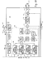
- FIG. 1 is a block diagram of an exemplary digital hearing aid system 12.
- the digital hearing aid system 12 includes several external components 14, 16, 18, 20, 22, 24, 26, 28, and, preferably, a single integrated circuit (IC) 12A.
- the external components include a pair of microphones 24, 26, a tele-coil 28, a volume control potentiometer 24, a memory-select toggle switch 16, battery terminals 18, 22, and a speaker 20.
- Sound is received by the pair of microphones 24, 26, and converted into electrical signals that are coupled to the FMIC 12C and RMIC 12D inputs to the IC 12A.
- FMIC refers to "front microphone”
- RMIC refers to "rear microphone.”
- the microphones 24, 26 are biased between a regulated voltage output from the RREG and FREG pins 12B, and the ground nodes FGND 12F, RGND 12G.
- the regulated voltage output on FREG and RREG is generated internally to the IC 12A by regulator 30.
- the tele-coil 28 is a device used in a hearing aid that magnetically couples to a telephone handset and produces an input current that is proportional to the telephone signal. This input current from the tele-coil 28 is coupled into the rear microphone A/D converter 32B on the IC 12A when the switch 76 is connected to the "T" input pin 12E, indicating that the user of the hearing aid is talking on a telephone.
- the tele-coil 28 is used to prevent acoustic feedback into the system when talking on the telephone.
- the volume control potentiometer 14 is coupled to the volume control input 12N of the IC. This variable resistor is used to set the volume sensitivity of the digital hearing aid.
- the memory-select toggle switch 16 is coupled between the positive voltage supply VB 18 to the IC 12A and the memory-select input pin 12L.
- This switch 16 is used to toggle the digital hearing aid system 12 between a series of setup configurations.
- the device may have been previously programmed for a variety of environmental settings, such as quiet listening, listening to music, a noisy setting, etc.
- the system parameters of the IC 12A may have been optimally configured for the particular user.
- the toggle switch 16 By repeatedly pressing the toggle switch 16, the user may then toggle through the various configurations stored in the read-only memory 44 of the IC 12A.
- the battery terminals 12K, 12H of the IC 12A are preferably coupled to a single 1.3 volt zinc-air battery. This battery provides the primary power source for the digital hearing aid system.
- the last external component is the speaker 20.
- This element is coupled to the differential outputs at pins 12J, 12I of the IC 12A, and converts the processed digital input signals from the two microphones 24, 26 into an audible signal for the user of the digital hearing aid system 12.
- a pair of A/D converters 32A, 32B are coupled between the front and rear microphones 24, 26, and the sound processor 38, and convert the analog input signals into the digital domain for digital processing by the sound processor 38.
- a single D/A converter 48 converts the processed digital signals back into the analog domain for output by the speaker 20.
- Other system elements include a regulator 30, a volume control A/D 40, an interface/system controller 42, an EEPROM memory 44, a power-on reset circuit 46, and a oscillator/system clock 36.
- the sound processor 38 preferably includes a directional processor and headroom expander 50, a pre-filter 52, a wide-band twin detector 54, a band-split filter 56, a plurality of narrow-band channel processing and twin detectors 58A-58D, a summer 60, a post filter 62, a notch filter 64, a volume control circuit 66, an automatic gain control output circuit 68, a peak clipping circuit 70, a squelch circuit 72, and a tone generator 74.
- a directional processor and headroom expander 50 preferably includes a directional processor and headroom expander 50, a pre-filter 52, a wide-band twin detector 54, a band-split filter 56, a plurality of narrow-band channel processing and twin detectors 58A-58D, a summer 60, a post filter 62, a notch filter 64, a volume control circuit 66, an automatic gain control output circuit 68, a peak clipping circuit 70, a squelch circuit 72
- the sound processor 38 processes digital sound as follows. Sound signals input to the front and rear microphones 24, 26 are coupled to the front and rear A/D converters 32A, 32B, which are preferably Sigma-Delta modulators followed by decimation filters that convert the analog sound inputs from the two microphones into a digital equivalent. Note that when a user of the digital hearing aid system is talking on the telephone, the rear A/D converter 32B is coupled to the tele-coil input "T" 12E via switch 76. Both of the front and rear A/D converters 32A, 32B are clocked with the output clock signal from the oscillator/system clock 36 (discussed in more detail below). This same output clock signal is also coupled to the sound processor 38 and the D/A converter 48.
- the front and rear A/D converters 32A, 32B are preferably Sigma-Delta modulators followed by decimation filters that convert the analog sound inputs from the two microphones into a digital equivalent. Note that when a user of the digital hearing aid system is talking on the telephone
- the front and rear digital sound signals from the two A/D converters 32A, 32B are coupled to the directional processor and headroom expander 50 of the sound processor 38.
- the rear A/D converter 32B is coupled to the processor 50 through switch 75. In a first position, the switch 75 couples the digital output of the rear A/D converter 32 B to the processor 50, and in a second position, the switch 75 couples the digital output of the rear A/D converter 32B to summation block 71 for the purpose of compensating for occlusion.
- Occlusion is the amplification of the users own voice within the ear canal.
- the rear microphone can be moved inside the ear canal to receive this unwanted signal created by the occlusion effect.
- the occlusion effect is usually reduced in these types of systems by putting a mechanical vent in the hearing aid. This vent, however, can cause an oscillation problem as the speaker signal feeds back to the microphone(s) through the vent aperture.
- Another problem associated with traditional venting is a reduced low frequency response (leading to reduced sound quality).
- Yet another limitation occurs when the direct coupling of ambient sounds results in poor directional performance, particularly in the low frequencies.
- the system shown in FIG. 1 solves these problems by canceling the unwanted signal received by the rear microphone 26 by feeding back the rear signal from the A/D converter 32B to summation circuit 71. The summation circuit 71 then subtracts the unwanted signal from the processed composite signal to thereby compensate for the occlusion effect.
- An more-detailed occlusion sub-system is described below with reference to FIGs.
- the directional processor and headroom expander 50 includes a combination of filtering and delay elements that, when applied to the two digital input signals, forms a single, directionally-sensitive response. This directionally-sensitive response is generated such that the gain of the directional processor 50 will be a maximum value for sounds coming from the front microphone 24 and will be a minimum value for sounds coming from the rear microphone 26.
- the headroom expander portion of the processor 50 significantly extends the dynamic range of the A/D conversion, which is very important for high fidelity audio signal processing. It does this by dynamically adjusting the A/D converters 32A/32B operating points.
- the headroom expander 50 adjusts the gain before and after the A/D conversion so that the total gain remains unchanged, but the intrinsic dynamic range of the A/D converter block 32A/32B is optimized to the level of the signal being processed.
- the headroom expander portion of the processor 50 is described below in more detail with reference to FIGs. 4 and 5.
- the output from the directional processor and headroom expander 50 is coupled to a pre-filter 52, which is a general-purpose filter for pre-conditioning the sound signal prior to any further signal processing steps.
- This "pre-conditioning" can take many forms, and, in combination with corresponding "post-conditioning" in the post filter 62, can be used to generate special effects that may be suited to only a particular class of users.
- the pre-filter 52 could be configured to mimic the transfer function of the user's middle ear, effectively putting the sound signal into the "cochlear domain.”
- Signal processing algorithms to correct a hearing impairment based on, for example, inner hair cell loss and outer hair cell loss, could be applied by the sound processor 38.
- the post-filter 62 could be configured with the inverse response of the pre-filter 52 in order to convert the sound signal back into the "acoustic domain" from the "cochlear domain.”
- the post-filter 62 could be configured with the inverse response of the pre-filter 52 in order to convert the sound signal back into the "acoustic domain" from the "cochlear domain.”
- other pre-conditioning/post-conditioning configurations and corresponding signal processing algorithms could be utilized.
- the pre-conditioned digital sound signal is then coupled to the band-split filter 56, which preferably includes a bank of filters with variable corner frequencies and pass-band gains. These filters are used to split the single input signal into four distinct frequency bands.
- the four output signals from the band-split filter 56 are preferably in-phase so that when they are summed together in block 60, after channel processing, nulls or peaks in the composite signal (from the summer) are minimized.
- Channel processing of the four distinct frequency bands from the band-split filter 56 is accomplished by a plurality of channel processing/twin detector blocks 58A-58D. Although four blocks are shown in FIG. 1, it should be clear that more than four (or less than four) frequency bands could be generated in the band-split filter 56, and thus more or less than four channel processing/twin detector blocks 58 may be utilized with the system.
- Each of the channel processing/twin detectors 58A-58D provide an automatic gain control (“AGC”) function that provides compression and gain on the particular frequency band (channel) being processed. Compression of the channel signals permits quieter sounds to be amplified at a higher gain than louder sounds, for which the gain is compressed. In this manner, the user of the system can hear the full range of sounds since the circuits 58A-58D compress the full range of normal hearing into the reduced dynamic range of the individual user as a function of the individual user's hearing loss within the particular frequency band of the channel.
- AGC automatic gain control
- the channel processing blocks 58A-58D can be configured to employ a twin detector average detection scheme while compressing the input signals.
- This twin detection scheme includes both slow and fast attack/release tracking modules that allow for fast response to transients (in the fast tracking module), while preventing annoying pumping of the input signal (in the slow tracking module) that only a fast time constant would produce.
- the outputs of the fast and slow tracking modules are compared, and the compression slope is then adjusted accordingly.
- the compression ratio, channel gain, lower and upper thresholds (return to linear point), and the fast and slow time constants (of the fast and slow tracking modules) can be independently programmed and saved in memory 44 for each of the plurality of channel processing blocks 58A-58D.
- FIG. 1 also shows a communication bus 59, which may include one or more connections, for coupling the plurality of channel processing blocks 58A-58D.
- This inter-channel communication bus 59 can be used to communicate information between the plurality of channel processing blocks 58A-58D such that each channel (frequency band) can take into account the "energy” level (or some other measure) from the other channel processing blocks.
- each channel processing block 58A-58D would take into account the "energy” level from the higher frequency channels.
- the "energy" level from the wide-band detector 54 may be used by each of the relatively narrow-band channel processing blocks 58A-58D when processing their individual input signals.
- the four channel signals are summed by summer 60 to form a composite signal.
- This composite signal is then coupled to the post-filter 62, which may apply a post-processing filter function as discussed above.
- the composite signal is then applied to a notch-filter 64, that attenuates a narrow band of frequencies that is adjustable in the frequency range where hearing aids tend to oscillate.
- This notch filter 64 is used to reduce feedback and prevent unwanted "whistling" of the device.
- the notch filter 64 may include a dynamic transfer function that changes the depth of the notch based upon the magnitude of the input signal.
- the composite signal is then coupled to a volume control circuit 66.
- the volume control circuit 66 receives a digital value from the volume control A/D 40, which indicates the desired volume level set by the user via potentiometer 14, and uses this stored digital value to set the gain of an included amplifier circuit.
- the composite signal is then coupled to the AGC-output block 68.
- the AGC-output circuit 68 is a high compression ratio, low distortion limiter that is used to prevent pathological signals from causing large scale distorted output signals from the speaker 20 that could be painful and annoying to the user of the device.
- the composite signal is coupled from the AGC-output circuit 68 to a squelch circuit 72, that performs an expansion on low-level signals below an adjustable threshold.
- the squelch circuit 72 uses an output signal from the wide-band detector 54 for this purpose. The expansion of the low-level signals attenuates noise from the microphones and other circuits when the input S/N ratio is small, thus producing a lower noise signal during quiet situations.
- a tone generator block 74 is also shown coupled to the squelch circuit 72, which is included for calibration and testing of the system.
- the output of the squelch circuit 72 is coupled to one input of summer 71.
- the other input to the summer 71 is from the output of the rear A/D converter 32B, when the switch 75 is in the second position.
- These two signals are summed in summer 71, and passed along to the interpolator and peak clipping circuit 70.
- This circuit 70 also operates on pathological signals, but it operates almost instantaneously to large peak signals and is high distortion limiting.
- the interpolator shifts the signal up in frequency as part of the D/A process and then the signal is clipped so that the distortion products do not alias back into the baseband frequency range.
- the output of the interpolator and peak clipping circuit 70 is coupled from the sound processor 38 to the D/A H-Bridge 48.
- This circuit 48 converts the digital representation of the input sound signals to a pulse density modulated representation with complimentary outputs. These outputs are coupled off-chip through outputs 12J, 12I to the speaker 20, which low-pass filters the outputs and produces an acoustic analog of the output signals.
- the D/A H-Bridge 48 includes an interpolator, a digital Delta-Sigma modulator, and an H-Bridge output stage.
- the D/A H-Bridge 48 is also coupled to and receives the clock signal from the oscillator/system clock 36 (described below).
- the interface/system controller 42 is coupled between a serial data interface pin 12M on the IC 12, and the sound processor 38. This interface is used to communicate with an external controller for the purpose of setting the parameters of the system. These parameters can be stored on-chip in the EEPROM 44. If a "black-out” or “brown-out” condition occurs, then the power-on reset circuit 46 can be used to signal the interface/system controller 42 to configure the system into a known state. Such a condition can occur, for example, if the battery fails.
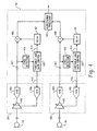
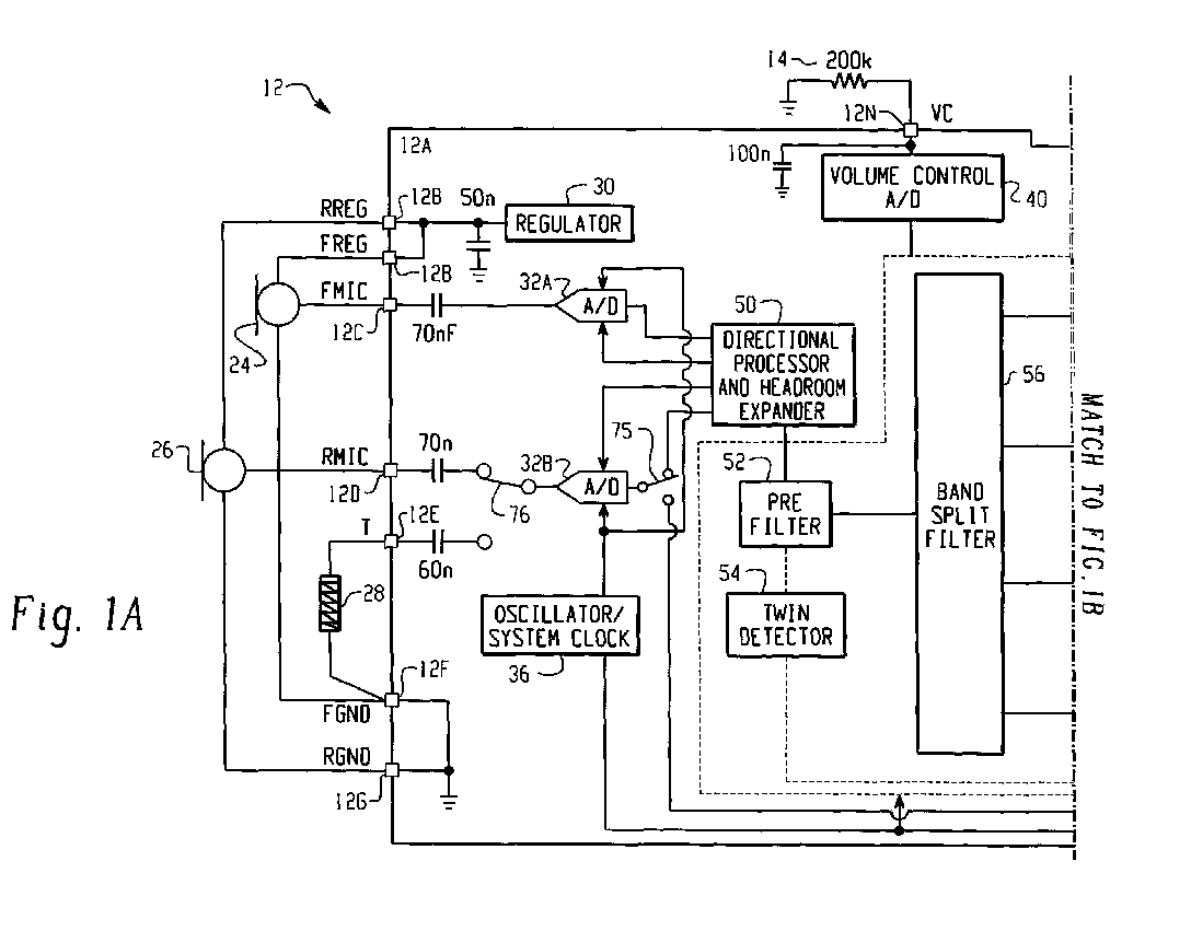
- FIG. 2 is a block diagram of an occlusion sub-system for the digital hearing aid system 12 shown in FIG. 1.
- the occlusion sub-system includes a number of components described above with reference to FIG. 1, including the front and rear microphones 24, 26, the front and rear microphone A/D converters 32A, 32B, the directional processor and headroom expander 50, the sound processor 38, the summation circuit 71, the peak clipping circuit 70, the D/A converter 48, and the speaker 20.
- the occlusion sub-system further includes a high frequency equalizer 203, an interpolator 204, a microphone equalization filter 200, a loop filter 202, and a speaker equalization filter 201.
- the occlusion sub-system includes two signal paths: (1) an intended signal received by the front microphone 24 and amplified for the hearing impaired user, and (2) an acoustical occlusion signal originating in the ear canal that is received by the rear microphone 26 and cancelled in a feedback loop by the occlusion sub-system.
- the intended signal received by the front microphone is converted from the analog to the digital domain with the front microphone A/D converter 32A.
- the front microphone A/D converter 32A includes an A/D conversion block 206 which converts the signal into the digital domain, and a decimator block 207 which down-samples the signal to achieve a lower-speed, higher-resolution digital signal.
- the decimator block 207 may, for example, down-sample the signal by a factor of sixty-four (64).
- the output from the front microphone A/D converter 32A is then coupled to the sound processor 38 which amplifies and conditions the signal as described above with reference to FIG. 1.
- the output from the sound processor 38 is filtered by the high frequency equalizer block 203.
- the characteristics of the high frequency equalizer block 203 are described below with reference to FIG. 3.
- the output from the high frequency equalizer block 203 is up-sampled by the interpolator 204, and coupled as a positive input to the summation circuit 71.
- the interpolator 204 may, for example, up-sample the signal by a factor of four (4).
- the interpolation block 204 is included to transform the low-rate signal processing output from the sound processor 38 and high frequency equalizer 203 to a medium-rate signal that may be used for the occlusion cancellation process.
- the acoustical occlusion signal received by the rear microphone 26 is similarly converted from the analog to the digital domain with the rear microphone A/D converter 32B.
- the rear microphone A/D converter 32B includes an A/D conversion block 208 which converts the occlusion signal to the digital domain and a decimator block 209 which down-samples the signal.
- the decimator block 209 may, for example, down-sample the occlusion signal by a factor of sixteen (16), resulting in lower-speed, higher-resolution signal characteristics that are desirable for both low power and low noise operation.
- the output from the rear microphone A/D converter 32A is coupled to the microphone equalizing circuit 200 which mirrors the magnitude response of the rear microphone 26 and A/D combination in order to yield an overall flat microphone effect that is desirable for optimal performance.
- the output of the microphone equalizing circuit 200 is then coupled as a negative input to the summation circuit 71.
- the output from the summation circuit 71 is coupled to the loop filter 202 which filters the signal to the optimal magnitude and phase characteristics necessary for stable closed-loop operation.
- the filter characteristics for the loop filter 202 necessary to obtain a stable closed loop operation are commonly understood by those skilled in the art of control system theory. Ideally, a gain greater than unity gain is desirable to achieve the beneficial results of negative feedback to reduce the occlusion effect.
- the loop gain should, however, be less than unity when the overall phase response passes through 180 degrees of shift. Otherwise, the overall feedback may become positive, resulting in system instability.
- the output from the loop filter 202 is coupled to the speaker equalization filter 201 which flattens the overall transfer function of the Interpolator 70, D/A 48 and speaker 20 combination. It should be understood, however, that the loop filter 202 and speaker equalization filter 201 could be combined into one filter block, but are separated in this description to improve clarity.
- the output of the speaker equalizer filter 201 is then coupled to the speaker 20 through the interpolator/peak clipper 70 and D/A converter 48, as described above with reference to FIG. 1.
- the filtered occlusion signal coupled as a negative input to the summation circuit 71 produces an overall negative feedback loop when coupled by blocks 202, 201, 70 and 48 to the speaker 20.
- the frequency at which the overall phase response of the occlusion sub-system approaches 180 degrees (zero phase margin) is as high as practically possible.
- Time delays resulting from inherent sample-based mathematical operations used in digital signal processing may produce excess phase delay.
- the common use of highly oversampled low resolution sigma delta analog to digital (and digital to analog) converters and their associated high-order decimators and interpolators may produce significant group delays leading to less then optimal performance from a system as described herein.
- the illustrated occlusion subsystem provides a mixed sample rate solution whereby the low time delay signal processing is performed at a higher sampling rate than the hearing loss compensation algorithms resulting in greatly reduced delays since the decimation and interpolator designs need not be as high order.
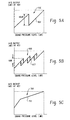
- FIG 3 is a graph 300 showing an exemplary frequency response C for the frequency equalizer block 203 shown in FIG 2.
- the frequency response for the frequency equalizer block 203 is illustrated as a dotted line labeled "C" on the graph 300.
- the graph 300 assumes ideal speaker and microphone equalization blocks 201, 200, such that the speaker and microphone transfer functions can be assumed to be flat (an ideal characteristic).
- Curve A illustrated on the graph 300 is a desired frequency response for the loop filter 202 in which the loop filter 202 exhibits greater than unity gain (or 0dB) at low frequencies, indicating negative feedback and the resultant reduction in the occlusion energy present in the ear canal.
- the open loop gain A reduces, crossing over the unity gain point at a frequency low enough to ensure stability while not unduly reducing the bandwidth over which this system operates (1KHz for example).
- the closed loop frequency response B should be nominally 0dB up to a frequency roughly equal to the unity gain frequency of the open loop gain A, and then follow the shape of the open loop response A for higher frequencies.
- an overall flat frequency response D may be achieved by implementing the filter shape shown as curve C with the high frequency equalizer block 203. This embodiment results in about 10dB of boost for frequencies above the transition frequency (1KHz in this example).
- FIG. 4 is a more detailed block diagram of the headroom expander 50 and A/D converters 32A, 32B shown in FIG 1.
- the front microphone and rear microphone A/D converters 32A, 32B include a preamplifier 405, an analog-to-digital conversion block 404, and a digital-to-analog conversion block 406.
- the headroom expander 50 includes two similar circuits, each circuit including a multiplier 400, a delay 401, a threshold/gain control block 402, and a level detector 403. Also shown are the front and rear microphones 24, 26 and a directional processor 410.
- the headroom expander circuits 400-403 optimize the operating point of the analog-to-digital converters 404 by adjusting the gain of the preamplifiers 405 in a controlled fashion while adjusting the gain of the multipliers 400 in a correspondingly opposite fashion.
- the overall gain from the input to the A/D converters 32A, 32B through to the output of the multipliers 400 is substantially independent of the actual gain of the preamplifiers 405.
- the gain applied by the preamplifiers 405 is in the analog domain while the gain adjustment by the multipliers 400 is in the digital domain, thus resulting in a mixed signal compression expander system that increases the effective dynamic range of the analog-to-digital converters 404.
- the analog signal generated by the front microphone 24 is coupled as an input to the preamplifier 405 which applies a variable gain that is controlled by a feedback signal from the threshold and gain control block 402.
- the amplified output from the preamplifier 405 is then converted to the digital domain by the analog-to-digital conversion block 404.
- the analog-to-digital conversion block 404 may, for example, be a Sigma-Delta modulator followed by decimation filters as described above with reference to FIGs. 1 and 2, or may be some other type of analog-to-digital converter.
- the digital output from the analog-to-digital conversion block 404 is coupled as inputs to the multiplier 400 and the level detector 403.
- the level detector 403 determines the magnitude of the output of the analog-to-digital conversion block 404, and generates an energy level output signal.
- the level detector 403 operates similarly to the twin detector 54 described above with reference to FIG. 1.
- the energy level output signal from the level detector 403 is coupled to the threshold and gain control block 402 which determines when the output of the analog-to-digital converter 404 is above a pre-defined level. If the output of the analog-to-digital converter 404 rises above the pre-defined level, then the threshold and gain control block 402 reduces the gain of the preamplifier 405 and proportionally increases the gain of the multiplier 400.
- the threshold and gain control block 402 controls the gain of the preamplifier 405 with a preamplifier control signal 412 that is converted to the analog domain by the digital-to-analog converter 406.
- the threshold and gain control block 402 adjusts the gain by generating an output gain control signal 414 which is delayed by the delay block 401 and is coupled as a second input to the multiplier 400.
- the delay introduced to the output gain control signal 414 by the delay block 401 is pre-selected to match the delay resulting from the process of analog to digital conversion (including any decimation) performed by the analog-to-digital conversion block 404. Exemplary gain adjustments that may be performed by the threshold and gain control block 402 are described below with reference to FIGs. 5a-5c.
- the signal from the rear microphone 26 is optimized by the rear microphone A/D converter 32B and the second headroom expander circuit 400-403.
- the outputs from the two multipliers 400 are then coupled as inputs to a directional processor 410.
- the directional processor 410 compares the two signals, and generates a directionally-sensitive response such that gain applied by the directional processor 410 has a maximum value for sounds coming from the front microphone 24 and a minimum value for sounds coming from the rear microphone 26.
- the directional processor 410 may, for example, be implemented as a delay sum beamformer, which is a configuration commonly understood by those skilled in the art.
- the directional processor 410 may also include a matching filter coupled in series with the delay sum beamformer that filters the signals from the front and rear microphone headroom expander circuits 400-403 such that the rear microphone frequency response is substantially the same as the front microphone frequency response.
- FIGs. 5a-5c are graphs 500, 600, 700 illustrating exemplary gain adjustments that may be performed by the threshold and gain control block 402 shown in FIG. 4.
- FIG 5a illustrates a single-step gain 502
- FIG 5b illustrates a multi-step gain 602
- FIG 5c illustrates a continuous gain 702.
- the vertical axis on each graph 500, 600, 700 represents the output of the analog-to-digital conversion block 404 , illustrated as node 407 in FIG. 4.
- the horizontal axis on each graph 500, 600, 700 represents the sound pressure level detected by the front and rear microphones 24, 26.
- the single-step gain 502 illustrated in FIG. 5a may be implemented by the threshold and gain control block 402 with only two gain levels for the preamplifier 405.
- the multi-step gain 602 illustrated in FIG 5b implements an 18dB gain change in three 6dB steps. Similar to the single-step gain implementation 500 described above, this implementation 600 enables the multiplier 400 to be realized through simple bit shifting. In addition, this multi-step gain implementation 602 adds hysteresis to the threshold levels of the analog-to-digital converter output 407. In this manner, gain switching activity is reduced leading to fewer opportunities for audible artifacts.
- the continuous gain 702 illustrated in FIG 5c requires the threshold and gain control block 402 to continuously adjust the gain of the preamplifier 405.
- the preamplifier 405 should have a continuously adjustable variable gain and the digital-to-analog converter 406 should have a higher resolution than necessary to implement the embodiments illustrated in FIGs 5a and 5b.
- the multiplier 400 should be a full multiplier having resolution greater than the simple arithmetic shifting techniques previously discussed.
Abstract
Description
Claims (15)
- A digital hearing aid, comprising:a front microphone that receives an acoustical intended signal and generates an analog intended signal;a front microphone analog-to-digital converter coupled to the front microphone that converts the analog intended signal to a digital intended signal;a rear microphone that receives an acoustical occlusion signal from the ear canal of a digital hearing aid user and generates an analog occlusion signal;a rear microphone analog-to-digital converter coupled to the rear microphone that converts the analog occlusion signal to a digital occlusion signal;a sound processor coupled to the front microphone analog-to-digital converter that selectively modifies the frequency response of the digital occlusion signal to match pre-selected signal characteristics and generates a processed intended signal;an occlusion sub-system coupled to the processed intended signal and the digital occlusion signal that subtracts the digital occlusion signal from the processed intended signal and generates an occlusion sub-system output signal;a digital-to-analog converter coupled to the occlusion sub-system that converts the occlusion sub-system output signal into an analog hearing aid output signal; anda speaker coupled to the digital-to-analog converter that converts the analog hearing aid output signal to an acoustical hearing aid output signal that is directed into the ear canal of the digital hearing aid user.
- The digital hearing aid of claim 1, wherein the occlusion sub-system comprises:a summation circuit having a positive input coupled to the processed intended signal and a negative input coupled to the digital occlusion signal that subtracts the digital occlusion signal from the processed intended signal and generates the occlusion sub-system output signal.
- The digital hearing aid of claim 1, wherein the occlusion sub-system comprises:a high frequency equalizer coupled to processed intended signal that applies a transfer function to the processed intended signal.
- The digital hearing aid of claim 3, wherein the occlusion sub-system further comprises:a loop filter coupled to the occlusion sub-system output that applies a transfer function to the occlusion sub-system output signal, wherein the transfer function applied by the high frequency equalizer is a function of the transfer function applied by the loop filter.
- The digital hearing aid of claim 1, wherein the front microphone analog-to digital converter samples the analog intended signal at a first sample rate and the rear microphone analog-to-digital converter samples the analog occlusion signal at a second sample rate, and wherein the occlusion sub-system comprises:an interpolator coupled to the processed intended signal that increases the first sample rate of the processed intended signal to match the second sample rate of the digital occlusion signal.
- The digital hearing aid of claim 1, wherein the occlusion sub-system comprises:a microphone equalizing filter coupled to the digital occlusion signal that applies a transfer function to the digital occlusion signal, wherein the transfer function is a function of the magnitude response of the rear microphone and the rear microphone analog-to-digital converter.
- The digital hearing aid of claim 1, wherein the occlusion sub-system comprises:a high frequency equalizer coupled to the processed intended signal that applies a transfer function to the processed intended signal and generates a high frequency equalizer output signal;a microphone equalizing filter coupled to the digital occlusion signal that applies a transfer function to the digital occlusion signal and generates a microphone equalizing filter output signal, wherein the transfer function is a function of the magnitude response of the rear microphone and the rear microphone analog-to-digital converter;a summation circuit having a positive input coupled to the high frequency equalizer output signal and a negative input coupled to the microphone equalizing filter output signal that subtracts the microphone equalizing output signal from the high frequency equalizer output signal to generate a summation circuit output signal;a loop filter coupled to the summation circuit output signal that applies a transfer function to the summation circuit output signal to generate a loop filter output signal, wherein the transfer function applied by the high frequency equalizer is a function of the transfer function applied by the loop filter; anda speaker equalizing filter coupled to the loop filter output signal that flattens the frequency response of speaker and generates the occlusion sub-system output signal.
- The digital hearing aid of claim 7, wherein the front microphone analog-to digital converter samples the analog intended signal at a first sample rate and the rear microphone analog-to-digital converter samples the analog occlusion signal at a second sample rate, and wherein the occlusion sub-system further comprises:an interpolator coupled to the high frequency equalizer output signal that increases the first sample rate of the high frequency equalizer output signal to match the second sample rate of the digital occlusion signal.
- The digital hearing aid of claim 7, wherein the occlusion sub-system further comprises:an interpolator and peak clipper coupled to the occlusion sub-system output signal that increases the frequency of the occlusion sub-system output signal and that limits the amplitude of the occlusion sub-system output signal to a pre-selected level in order to minimize the effects of aliasing.
- A digital hearing aid, comprising:a front microphone that receives a front acoustical signal and generates a front microphone analog signal;a front microphone analog-to-digital converter coupled to the front microphone that converts the front microphone analog signal into a front microphone digital signal, wherein the front microphone analog-to-digital converter includes a front microphone preamplifier that applies a gain to the front microphone analog signal prior to conversion into the digital domain;a front microphone headroom expander coupled to the front microphone analog-to-digital converter that applies a gain to the front microphone digital signal to generate a front microphone headroom expander output signal, wherein the front microphone headroom expander is configured to detect the energy level of the front microphone digital signal and vary the gain applied by the front microphone preamplifier as a function of the detected energy level;a sound processor coupled to the front microphone headroom expander output signal that selectively modifies the frequency response of the front microphone headroom expander output signal to match pre-selected signal characteristics and generates a processed signal;a digital-to-analog converter coupled to the sound processor that converts the processed output into an analog hearing aid output signal; anda speaker coupled to the digital-to-analog converter that converts the analog hearing aid output signal into an acoustical hearing aid output signal that is directed into the ear canal of the digital hearing aid user.
- The digital hearing aid of claim 10, further comprising:wherein the sound processor is also coupled to the rear microphone headroom expander output signal and selectively modifies the frequency response of the rear microphone headroom expander output signal to match pre-selected signal characteristics and generate the processed signal.a rear microphone that receives a rear acoustical signal and generates a rear microphone analog signal;a rear microphone analog-to-digital converter coupled to the rear microphone that converts the rear microphone analog signal to a rear microphone digital signal, wherein the rear microphone analog-to-digital converter includes a rear microphone preamplifier that applies a gain to the rear microphone analog signal prior to conversion to the digital domain; anda rear microphone headroom expander coupled to the rear microphone analog-to-digital converter that applies a gain to the rear microphone digital signal to generate a rear microphone headroom expander output signal, wherein the rear microphone headroom expander is configured to detect the energy level of the rear microphone digital signal and vary the gain applied by the rear microphone preamplifier as a function of the detected energy level;
- The digital hearing aid of claim 10, wherein the front microphone headroom expander varies the gain applied to the front microphone digital signal is proportion to the gain applied by the front microphone preamplifier.
- The digital hearing aid of claim 11, further comprising:a directional processor coupled to the front microphone headroom expander output signal and the rear microphone headroom expander output signal that reduces the gain of the rear microphone headroom expander output signal in relation to the gain of the front microphone headroom expander output signal.
- The digital hearing aid of claim 13, wherein the directional processor comprises a delay sum beamformer.
- The digital hearing aid of claim 14, wherein the directional processor further comprises a matching filter coupled in series with the delay sum beamformer that filters the front and rear microphone headroom expander output signals such that the frequency response of the front microphone is substantially equal to the frequency response of the rear microphone.
Applications Claiming Priority (2)
| Application Number | Priority Date | Filing Date | Title |
|---|---|---|---|
| US28331001P | 2001-04-12 | 2001-04-12 | |
| US283310P | 2001-04-12 |
Publications (4)
| Publication Number | Publication Date |
|---|---|
| EP1251714A2 true EP1251714A2 (en) | 2002-10-23 |
| EP1251714A3 EP1251714A3 (en) | 2004-08-04 |
| EP1251714B1 EP1251714B1 (en) | 2011-10-05 |
| EP1251714B2 EP1251714B2 (en) | 2015-06-03 |
Family
ID=23085430
Family Applications (1)
| Application Number | Title | Priority Date | Filing Date |
|---|---|---|---|
| EP02008393.7A Expired - Lifetime EP1251714B2 (en) | 2001-04-12 | 2002-04-12 | Digital hearing aid system |
Country Status (3)
| Country | Link |
|---|---|
| US (2) | US6937738B2 (en) |
| EP (1) | EP1251714B2 (en) |
| DK (1) | DK1251714T4 (en) |
Cited By (10)
| Publication number | Priority date | Publication date | Assignee | Title |
|---|---|---|---|---|
| EP1673960A1 (en) * | 2003-10-14 | 2006-06-28 | Gennum Corporation | Communication headset with signal processing capability |
| EP1744589A2 (en) | 2005-07-11 | 2007-01-17 | Siemens Audiologische Technik GmbH | Hearing device and corresponding method for ownvoices detection |
| EP1786236A1 (en) * | 2005-11-09 | 2007-05-16 | Stephen R. Schwartz | Complementary-pair equalizer |
| DE102006029726A1 (en) * | 2006-06-28 | 2008-01-10 | Siemens Audiologische Technik Gmbh | Hearing aid |
| WO2008043793A1 (en) * | 2006-10-10 | 2008-04-17 | Siemens Audiologische Technik Gmbh | Hearing aid having an occlusion reduction unit, and method for occlusion reduction |
| US7512245B2 (en) | 2003-02-25 | 2009-03-31 | Oticon A/S | Method for detection of own voice activity in a communication device |
| EP2712211A1 (en) * | 2012-09-25 | 2014-03-26 | GN Resound A/S | Hearing aid for providing phone signals |
| EP1537759B1 (en) * | 2002-09-02 | 2014-07-23 | Oticon A/S | Method for counteracting the occlusion effects |
| US9288584B2 (en) | 2012-09-25 | 2016-03-15 | Gn Resound A/S | Hearing aid for providing phone signals |
| EP2991379B1 (en) | 2014-08-28 | 2017-05-17 | Sivantos Pte. Ltd. | Method and device for improved perception of own voice |
Families Citing this family (98)
| Publication number | Priority date | Publication date | Assignee | Title |
|---|---|---|---|---|
| US6937738B2 (en) * | 2001-04-12 | 2005-08-30 | Gennum Corporation | Digital hearing aid system |
| DE60223869D1 (en) * | 2001-04-18 | 2008-01-17 | Gennum Corp | Digital quasi-mean detector |
| EP1251715B2 (en) | 2001-04-18 | 2010-12-01 | Sound Design Technologies Ltd. | Multi-channel hearing instrument with inter-channel communication |
| WO2003084287A1 (en) * | 2001-10-12 | 2003-10-09 | Etymotic Research, Inc. | High fidelity digital hearing aid and methods of programming and operating same |
| US7630507B2 (en) * | 2002-01-28 | 2009-12-08 | Gn Resound A/S | Binaural compression system |
| US7536022B2 (en) * | 2002-10-02 | 2009-05-19 | Phonak Ag | Method to determine a feedback threshold in a hearing device |
| US7010135B2 (en) * | 2002-10-02 | 2006-03-07 | Phonak Ag | Method to determine a feedback threshold in a hearing device |
| US7305100B2 (en) * | 2003-02-14 | 2007-12-04 | Gn Resound A/S | Dynamic compression in a hearing aid |
| WO2004075162A2 (en) * | 2003-02-20 | 2004-09-02 | Ramot At Tel Aviv University Ltd. | Method apparatus and system for processing acoustic signals |
| US7184564B2 (en) * | 2003-05-30 | 2007-02-27 | Starkey Laboratories, Inc. | Multi-parameter hearing aid |
| US20050058313A1 (en) * | 2003-09-11 | 2005-03-17 | Victorian Thomas A. | External ear canal voice detection |
| KR20050053139A (en) * | 2003-12-02 | 2005-06-08 | 삼성전자주식회사 | Method and apparatus for compensating sound field using peak and dip frequency |
| CA2555157C (en) * | 2004-03-03 | 2010-04-27 | Widex A/S | Hearing aid comprising adaptive feedback suppression system |
| EP3157271A1 (en) * | 2004-03-05 | 2017-04-19 | Etymotic Research, Inc | Companion microphone system and method |
| US7668328B2 (en) * | 2004-04-20 | 2010-02-23 | Starkey Laboratories, Inc. | Adjusting and display tool and potentiometer |
| US7688985B2 (en) * | 2004-04-30 | 2010-03-30 | Phonak Ag | Automatic microphone matching |
| WO2006037156A1 (en) * | 2004-10-01 | 2006-04-13 | Hear Works Pty Ltd | Acoustically transparent occlusion reduction system and method |
| US8027732B2 (en) * | 2005-02-15 | 2011-09-27 | Advanced Bionics, Llc | Integrated phase-shift power control transmitter for use with implantable device and method for use of the same |
| US20060211910A1 (en) * | 2005-03-18 | 2006-09-21 | Patrik Westerkull | Microphone system for bone anchored bone conduction hearing aids |
| US20070183609A1 (en) * | 2005-12-22 | 2007-08-09 | Jenn Paul C C | Hearing aid system without mechanical and acoustic feedback |
| JP4359599B2 (en) * | 2006-02-28 | 2009-11-04 | リオン株式会社 | hearing aid |
| GB2446966B (en) * | 2006-04-12 | 2010-07-07 | Wolfson Microelectronics Plc | Digital circuit arrangements for ambient noise-reduction |
| US7957548B2 (en) * | 2006-05-16 | 2011-06-07 | Phonak Ag | Hearing device with transfer function adjusted according to predetermined acoustic environments |
| US8199919B2 (en) | 2006-06-01 | 2012-06-12 | Personics Holdings Inc. | Earhealth monitoring system and method II |
| US8917876B2 (en) | 2006-06-14 | 2014-12-23 | Personics Holdings, LLC. | Earguard monitoring system |
| US20080123866A1 (en) * | 2006-11-29 | 2008-05-29 | Rule Elizabeth L | Hearing instrument with acoustic blocker, in-the-ear microphone and speaker |
| US8014548B2 (en) * | 2006-12-14 | 2011-09-06 | Phonak Ag | Hearing instrument, and a method of operating a hearing instrument |
| JP4882773B2 (en) | 2007-02-05 | 2012-02-22 | ソニー株式会社 | Signal processing apparatus and signal processing method |
| JP4922023B2 (en) * | 2007-03-09 | 2012-04-25 | 株式会社東芝 | Analog-digital conversion device, wireless communication terminal, and program |
| US20080226104A1 (en) * | 2007-03-16 | 2008-09-18 | Mark Hedstrom | Wireless handsfree device and hearing aid |
| US7365669B1 (en) * | 2007-03-28 | 2008-04-29 | Cirrus Logic, Inc. | Low-delay signal processing based on highly oversampled digital processing |
| WO2008153589A2 (en) * | 2007-06-01 | 2008-12-18 | Personics Holdings Inc. | Earhealth monitoring system and method iv |
| DK2023664T3 (en) * | 2007-08-10 | 2013-06-03 | Oticon As | Active noise cancellation in hearing aids |
| US8582793B2 (en) * | 2007-09-20 | 2013-11-12 | Phonak Ag | Method for determining of feedback threshold in a hearing device and a hearing device |
| US20110026746A1 (en) * | 2007-09-20 | 2011-02-03 | Phonak Ag | Method for determining of feedback threshold in a hearing device and a hearing device |
| US8238590B2 (en) * | 2008-03-07 | 2012-08-07 | Bose Corporation | Automated audio source control based on audio output device placement detection |
| US8107654B2 (en) | 2008-05-21 | 2012-01-31 | Starkey Laboratories, Inc | Mixing of in-the-ear microphone and outside-the-ear microphone signals to enhance spatial perception |
| US8831936B2 (en) * | 2008-05-29 | 2014-09-09 | Qualcomm Incorporated | Systems, methods, apparatus, and computer program products for speech signal processing using spectral contrast enhancement |
| US8538749B2 (en) | 2008-07-18 | 2013-09-17 | Qualcomm Incorporated | Systems, methods, apparatus, and computer program products for enhanced intelligibility |
| US8675461B1 (en) | 2008-08-25 | 2014-03-18 | Marvell International Ltd. | Adjusting a defect threshold |
| WO2010034337A1 (en) * | 2008-09-23 | 2010-04-01 | Phonak Ag | Hearing system and method for operating such a system |
| US8150057B2 (en) * | 2008-12-31 | 2012-04-03 | Etymotic Research, Inc. | Companion microphone system and method |
| DE102009010892B4 (en) * | 2009-02-27 | 2012-06-21 | Siemens Medical Instruments Pte. Ltd. | Apparatus and method for reducing impact sound effects in hearing devices with active occlusion reduction |
| DE102009014053B4 (en) * | 2009-03-19 | 2012-11-22 | Siemens Medical Instruments Pte. Ltd. | Method for setting a directional characteristic and hearing devices |
| US8243946B2 (en) * | 2009-03-30 | 2012-08-14 | Bose Corporation | Personal acoustic device position determination |
| US8238570B2 (en) * | 2009-03-30 | 2012-08-07 | Bose Corporation | Personal acoustic device position determination |
| US8699719B2 (en) * | 2009-03-30 | 2014-04-15 | Bose Corporation | Personal acoustic device position determination |
| US8238567B2 (en) * | 2009-03-30 | 2012-08-07 | Bose Corporation | Personal acoustic device position determination |
| US9219964B2 (en) | 2009-04-01 | 2015-12-22 | Starkey Laboratories, Inc. | Hearing assistance system with own voice detection |
| US8477973B2 (en) | 2009-04-01 | 2013-07-02 | Starkey Laboratories, Inc. | Hearing assistance system with own voice detection |
| US8477957B2 (en) * | 2009-04-15 | 2013-07-02 | Nokia Corporation | Apparatus, method and computer program |
| US9202456B2 (en) * | 2009-04-23 | 2015-12-01 | Qualcomm Incorporated | Systems, methods, apparatus, and computer-readable media for automatic control of active noise cancellation |
| US8532310B2 (en) | 2010-03-30 | 2013-09-10 | Bose Corporation | Frequency-dependent ANR reference sound compression |
| US8073150B2 (en) * | 2009-04-28 | 2011-12-06 | Bose Corporation | Dynamically configurable ANR signal processing topology |
| US8315405B2 (en) * | 2009-04-28 | 2012-11-20 | Bose Corporation | Coordinated ANR reference sound compression |
| US8611553B2 (en) | 2010-03-30 | 2013-12-17 | Bose Corporation | ANR instability detection |
| US8165313B2 (en) * | 2009-04-28 | 2012-04-24 | Bose Corporation | ANR settings triple-buffering |
| US8073151B2 (en) * | 2009-04-28 | 2011-12-06 | Bose Corporation | Dynamically configurable ANR filter block topology |
| US8184822B2 (en) * | 2009-04-28 | 2012-05-22 | Bose Corporation | ANR signal processing topology |
| US8472637B2 (en) | 2010-03-30 | 2013-06-25 | Bose Corporation | Variable ANR transform compression |
| US8090114B2 (en) * | 2009-04-28 | 2012-01-03 | Bose Corporation | Convertible filter |
| US7928886B2 (en) * | 2009-07-01 | 2011-04-19 | Infineon Technologies Ag | Emulation of analog-to-digital converter characteristics |
| DK2302952T3 (en) * | 2009-08-28 | 2012-11-19 | Siemens Medical Instr Pte Ltd | Self-adaptation of a hearing aid |
| JP5424853B2 (en) * | 2009-12-21 | 2014-02-26 | ラピスセミコンダクタ株式会社 | Signal processing apparatus and signal processing method |
| US8923523B2 (en) | 2010-03-25 | 2014-12-30 | King Fahd University Of Petroleum And Minerals | Selective filtering earplugs |
| US9053697B2 (en) | 2010-06-01 | 2015-06-09 | Qualcomm Incorporated | Systems, methods, devices, apparatus, and computer program products for audio equalization |
| KR20130030765A (en) * | 2010-07-05 | 2013-03-27 | 비덱스 에이/에스 | System and method for measuring and validating the occlusion effect of a hearing aid user |
| US8494201B2 (en) | 2010-09-22 | 2013-07-23 | Gn Resound A/S | Hearing aid with occlusion suppression |
| US8594353B2 (en) | 2010-09-22 | 2013-11-26 | Gn Resound A/S | Hearing aid with occlusion suppression and subsonic energy control |
| EP2434780B1 (en) | 2010-09-22 | 2016-04-13 | GN ReSound A/S | Hearing aid with occlusion suppression and subsonic energy control |
| US20120155667A1 (en) * | 2010-12-16 | 2012-06-21 | Nair Vijayakumaran V | Adaptive noise cancellation |
| US8442253B2 (en) | 2011-01-26 | 2013-05-14 | Brainstorm Audio, Llc | Hearing aid |
| EP2482566B1 (en) * | 2011-01-28 | 2014-07-16 | Sony Ericsson Mobile Communications AB | Method for generating an audio signal |
| WO2012103935A1 (en) | 2011-02-01 | 2012-08-09 | Phonak Ag | Hearing device with a receiver module and method for manufacturing a receiver module |
| EP2512157B1 (en) * | 2011-04-13 | 2013-11-20 | Oticon A/s | Hearing device with automatic clipping prevention and corresponding method |
| JP2013098691A (en) * | 2011-10-31 | 2013-05-20 | Ricoh Co Ltd | Volume control circuit |
| EP2608569B1 (en) | 2011-12-22 | 2014-07-23 | ST-Ericsson SA | Digital microphone device with extended dynamic range |
| US9467774B2 (en) | 2012-02-10 | 2016-10-11 | Infineon Technologies Ag | System and method for a PCM interface for a capacitive signal source |
| KR101225678B1 (en) * | 2012-09-17 | 2013-01-24 | (주)알고코리아 | Auto-steering directional hearing aid and method of operation thereof |
| US10043535B2 (en) * | 2013-01-15 | 2018-08-07 | Staton Techiya, Llc | Method and device for spectral expansion for an audio signal |
| WO2014171920A1 (en) * | 2013-04-15 | 2014-10-23 | Nuance Communications, Inc. | System and method for addressing acoustic signal reverberation |
| US9084050B2 (en) | 2013-07-12 | 2015-07-14 | Elwha Llc | Systems and methods for remapping an audio range to a human perceivable range |
| US9232322B2 (en) * | 2014-02-03 | 2016-01-05 | Zhimin FANG | Hearing aid devices with reduced background and feedback noises |
| EP3251376B1 (en) | 2015-01-22 | 2022-03-16 | Eers Global Technologies Inc. | Active hearing protection device and method therefore |
| US9723415B2 (en) * | 2015-06-19 | 2017-08-01 | Gn Hearing A/S | Performance based in situ optimization of hearing aids |
| US9401158B1 (en) | 2015-09-14 | 2016-07-26 | Knowles Electronics, Llc | Microphone signal fusion |
| US9830930B2 (en) | 2015-12-30 | 2017-11-28 | Knowles Electronics, Llc | Voice-enhanced awareness mode |
| US9779716B2 (en) | 2015-12-30 | 2017-10-03 | Knowles Electronics, Llc | Occlusion reduction and active noise reduction based on seal quality |
| US9812149B2 (en) | 2016-01-28 | 2017-11-07 | Knowles Electronics, Llc | Methods and systems for providing consistency in noise reduction during speech and non-speech periods |
| EP3443755A4 (en) * | 2016-04-11 | 2019-10-09 | Gajstut, Enrique | Audio amplification electronic device with independent pitch and bass response adjustment |
| US9860626B2 (en) | 2016-05-18 | 2018-01-02 | Bose Corporation | On/off head detection of personal acoustic device |
| US9838812B1 (en) | 2016-11-03 | 2017-12-05 | Bose Corporation | On/off head detection of personal acoustic device using an earpiece microphone |
| US11012792B2 (en) | 2017-01-31 | 2021-05-18 | Widex A/S | Method of operating a hearing aid system and a hearing aid system |
| DK201700062A1 (en) | 2017-01-31 | 2018-09-11 | Widex A/S | Method of operating a hearing aid system and a hearing aid system |
| US10511915B2 (en) * | 2018-02-08 | 2019-12-17 | Facebook Technologies, Llc | Listening device for mitigating variations between environmental sounds and internal sounds caused by the listening device blocking an ear canal of a user |
| US10951996B2 (en) | 2018-06-28 | 2021-03-16 | Gn Hearing A/S | Binaural hearing device system with binaural active occlusion cancellation |
| DE102019213810B3 (en) | 2019-09-11 | 2020-11-19 | Sivantos Pte. Ltd. | Method for operating a hearing aid and hearing aid |
| EP3799444A1 (en) * | 2019-09-25 | 2021-03-31 | Oticon A/s | A hearing aid comprising a directional microphone system |
Citations (12)
| Publication number | Priority date | Publication date | Assignee | Title |
|---|---|---|---|---|
| US5033090A (en) * | 1988-03-18 | 1991-07-16 | Oticon A/S | Hearing aid, especially of the in-the-ear type |
| US5182774A (en) † | 1990-07-20 | 1993-01-26 | Telex Communications, Inc. | Noise cancellation headset |
| US5201006A (en) * | 1989-08-22 | 1993-04-06 | Oticon A/S | Hearing aid with feedback compensation |
| JPH06233389A (en) † | 1993-02-05 | 1994-08-19 | Sony Corp | Hearing aid |
| US5687241A (en) * | 1993-12-01 | 1997-11-11 | Topholm & Westermann Aps | Circuit arrangement for automatic gain control of hearing aids |
| DE19624092A1 (en) * | 1996-05-06 | 1997-11-13 | Siemens Audiologische Technik | Amplification circuit e.g. for analogue or digital hearing aid |
| US5724433A (en) * | 1993-04-07 | 1998-03-03 | K/S Himpp | Adaptive gain and filtering circuit for a sound reproduction system |
| US5848171A (en) * | 1994-07-08 | 1998-12-08 | Sonix Technologies, Inc. | Hearing aid device incorporating signal processing techniques |
| DE19822021A1 (en) * | 1998-05-15 | 1999-12-02 | Siemens Audiologische Technik | Hearing aid with automatic microphone tuning |
| WO2000028784A1 (en) † | 1998-11-09 | 2000-05-18 | Tøpholm & Westermann APS | Method for in-situ measuring and in-situ correcting or adjusting a signal process in a hearing aid with a reference signal processor |
| DE19935013C1 (en) * | 1999-07-26 | 2000-11-30 | Siemens Audiologische Technik | Digital programmable hearing aid |
| EP1154673A1 (en) † | 2000-05-12 | 2001-11-14 | Oticon A/S | Combining two signals in a hearing aid |
Family Cites Families (92)
| Publication number | Priority date | Publication date | Assignee | Title |
|---|---|---|---|---|
| GB1592168A (en) | 1976-11-29 | 1981-07-01 | Oticon Electronics As | Hearing aids |
| DE2658301C2 (en) | 1976-12-22 | 1978-12-07 | Siemens Ag, 1000 Berlin Und 8000 Muenchen | Hearing aid |
| DE2716336B1 (en) | 1977-04-13 | 1978-07-06 | Siemens Ag | Procedure and hearing aid for the compensation of hearing defects |
| DE2908999C2 (en) | 1979-03-08 | 1982-06-09 | Siemens AG, 1000 Berlin und 8000 München | Method for generating acoustic speech signals which are understandable for the extremely hard of hearing and device for carrying out this method |
| NL8001592A (en) | 1980-03-18 | 1981-10-16 | Philips Nv | MFB SYSTEM WITH A TAKEOVER NETWORK. |
| US4403118A (en) | 1980-04-25 | 1983-09-06 | Siemens Aktiengesellschaft | Method for generating acoustical speech signals which can be understood by persons extremely hard of hearing and a device for the implementation of said method |
| DE3131193A1 (en) | 1981-08-06 | 1983-02-24 | Siemens AG, 1000 Berlin und 8000 München | DEVICE FOR COMPENSATING HEALTH DAMAGE |
| DE3205685A1 (en) | 1982-02-17 | 1983-08-25 | Robert Bosch Gmbh, 7000 Stuttgart | HOERGERAET |
| DE3205686A1 (en) | 1982-02-17 | 1983-08-25 | Robert Bosch Gmbh, 7000 Stuttgart | HOERGERAET |
| US4494074A (en) | 1982-04-28 | 1985-01-15 | Bose Corporation | Feedback control |
| US4455675A (en) | 1982-04-28 | 1984-06-19 | Bose Corporation | Headphoning |
| US4689818A (en) | 1983-04-28 | 1987-08-25 | Siemens Hearing Instruments, Inc. | Resonant peak control |
| US4592087B1 (en) | 1983-12-08 | 1996-08-13 | Knowles Electronics Inc | Class D hearing aid amplifier |
| US4696032A (en) | 1985-02-26 | 1987-09-22 | Siemens Corporate Research & Support, Inc. | Voice switched gain system |
| US4644581A (en) | 1985-06-27 | 1987-02-17 | Bose Corporation | Headphone with sound pressure sensing means |
| DE8529437U1 (en) | 1985-10-16 | 1987-06-11 | Siemens Ag, 1000 Berlin Und 8000 Muenchen, De | |
| EP0219025B1 (en) | 1985-10-16 | 1990-06-13 | Siemens Aktiengesellschaft | Hearing aid |
| US5029217A (en) | 1986-01-21 | 1991-07-02 | Harold Antin | Digital hearing enhancement apparatus |
| US4947432B1 (en) | 1986-02-03 | 1993-03-09 | Programmable hearing aid | |
| FR2595498B1 (en) | 1986-03-07 | 1989-06-02 | Centre Nat Rech Scient | METHODS AND DEVICES FOR MITIGATING EXTERNAL NOISE ARISING AT TYMPAN AND IMPROVING THE INTELLIGIBILITY OF ELECTROACOUSTIC COMMUNICATIONS |
| US4750207A (en) | 1986-03-31 | 1988-06-07 | Siemens Hearing Instruments, Inc. | Hearing aid noise suppression system |
| GB8717043D0 (en) | 1987-07-20 | 1987-08-26 | Plessey Co Plc | Noise reduction systems |
| DE3734946A1 (en) | 1987-10-15 | 1989-05-03 | Siemens Ag | HEARING DEVICE WITH POSSIBILITY TO TELEPHONE |
| DE3802903A1 (en) | 1988-02-01 | 1989-08-10 | Siemens Ag | LANGUAGE TRANSFER DEVICE |
| US4852175A (en) | 1988-02-03 | 1989-07-25 | Siemens Hearing Instr Inc | Hearing aid signal-processing system |
| US4882762A (en) | 1988-02-23 | 1989-11-21 | Resound Corporation | Multi-band programmable compression system |
| US5111419A (en) | 1988-03-23 | 1992-05-05 | Central Institute For The Deaf | Electronic filters, signal conversion apparatus, hearing aids and methods |
| US4989251A (en) | 1988-05-10 | 1991-01-29 | Diaphon Development Ab | Hearing aid programming interface and method |
| US4868880A (en) | 1988-06-01 | 1989-09-19 | Yale University | Method and device for compensating for partial hearing loss |
| US4985925A (en) | 1988-06-24 | 1991-01-15 | Sensor Electronics, Inc. | Active noise reduction system |
| DE3834962A1 (en) | 1988-10-13 | 1990-04-19 | Siemens Ag | DIGITAL PROGRAMMING DEVICE FOR HOUR DEVICES |
| DE3900588A1 (en) | 1989-01-11 | 1990-07-19 | Toepholm & Westermann | REMOTE CONTROLLED, PROGRAMMABLE HOUR DEVICE SYSTEM |
| US4947433A (en) | 1989-03-29 | 1990-08-07 | Siemens Hearing Instruments, Inc. | Circuit for use in programmable hearing aids |
| US5033082A (en) | 1989-07-31 | 1991-07-16 | Nelson Industries, Inc. | Communication system with active noise cancellation |
| NO169689C (en) | 1989-11-30 | 1992-07-22 | Nha As | PROGRAMMABLE HYBRID HEARING DEVICE WITH DIGITAL SIGNAL TREATMENT AND PROCEDURE FOR DETECTION AND SIGNAL TREATMENT AT THE SAME. |
| DE59008542D1 (en) | 1990-07-25 | 1995-03-30 | Siemens Audiologische Technik | Hearing aid circuit with an output stage with a limiting device. |
| DK0480097T3 (en) | 1990-10-12 | 1995-06-06 | Siemens Audiologische Technik | Hearing aid with a data warehouse |
| US5278912A (en) | 1991-06-28 | 1994-01-11 | Resound Corporation | Multiband programmable compression system |
| US5247581A (en) | 1991-09-27 | 1993-09-21 | Exar Corporation | Class-d bicmos hearing aid output amplifier |
| US5389829A (en) | 1991-09-27 | 1995-02-14 | Exar Corporation | Output limiter for class-D BICMOS hearing aid output amplifier |
| US5267321A (en) | 1991-11-19 | 1993-11-30 | Edwin Langberg | Active sound absorber |
| US5347587A (en) | 1991-11-20 | 1994-09-13 | Sharp Kabushiki Kaisha | Speaker driving device |
| DE9321583U1 (en) | 1992-02-27 | 2000-05-25 | Siemens Audiologische Technik | Hearing aid worn on the head |
| US5241310A (en) | 1992-03-02 | 1993-08-31 | General Electric Company | Wide dynamic range delta sigma analog-to-digital converter with precise gain tracking |
| US5251263A (en) | 1992-05-22 | 1993-10-05 | Andrea Electronics Corporation | Adaptive noise cancellation and speech enhancement system and apparatus therefor |
| US5448644A (en) | 1992-06-29 | 1995-09-05 | Siemens Audiologische Technik Gmbh | Hearing aid |
| EP0576701B1 (en) | 1992-06-29 | 1996-01-03 | Siemens Audiologische Technik GmbH | Hearing aid |
| GB2274757A (en) | 1993-01-28 | 1994-08-03 | Secr Defence | Ear defenders employing active noise control |
| US5452361A (en) | 1993-06-22 | 1995-09-19 | Noise Cancellation Technologies, Inc. | Reduced VLF overload susceptibility active noise cancellation headset |
| WO1995000946A1 (en) | 1993-06-23 | 1995-01-05 | Noise Cancellation Technologies, Inc. | Variable gain active noise cancellation system with improved residual noise sensing |
| DE4321788C1 (en) | 1993-06-30 | 1994-08-18 | Siemens Audiologische Technik | Interface for serial data transmission between a hearing aid and a control device |
| US5376892A (en) | 1993-07-26 | 1994-12-27 | Texas Instruments Incorporated | Sigma delta saturation detector and soft resetting circuit |
| US5608803A (en) | 1993-08-05 | 1997-03-04 | The University Of New Mexico | Programmable digital hearing aid |
| US5412734A (en) | 1993-09-13 | 1995-05-02 | Thomasson; Samuel L. | Apparatus and method for reducing acoustic feedback |
| US5479522A (en) | 1993-09-17 | 1995-12-26 | Audiologic, Inc. | Binaural hearing aid |
| EP0585976A3 (en) | 1993-11-10 | 1994-06-01 | Phonak Ag | Hearing aid with cancellation of acoustic feedback |
| EP0674464A1 (en) | 1994-03-23 | 1995-09-27 | Siemens Audiologische Technik GmbH | Programmable hearing aid with fuzzy logic controller |
| EP0674463A1 (en) | 1994-03-23 | 1995-09-27 | Siemens Audiologische Technik GmbH | Programmable hearing aid |
| EP0676909A1 (en) | 1994-03-31 | 1995-10-11 | Siemens Audiologische Technik GmbH | Programmable hearing aid |
| DE59410235D1 (en) | 1994-05-06 | 2003-03-06 | Siemens Audiologische Technik | Programmable hearing aid |
| EP0712261A1 (en) | 1994-11-10 | 1996-05-15 | Siemens Audiologische Technik GmbH | Programmable hearing aid |
| DE4441996A1 (en) | 1994-11-26 | 1996-05-30 | Toepholm & Westermann | Hearing aid |
| US5577511A (en) * | 1995-03-29 | 1996-11-26 | Etymotic Research, Inc. | Occlusion meter and associated method for measuring the occlusion of an occluding object in the ear canal of a subject |
| US5740258A (en) | 1995-06-05 | 1998-04-14 | Mcnc | Active noise supressors and methods for use in the ear canal |
| US5862238A (en) | 1995-09-11 | 1999-01-19 | Starkey Laboratories, Inc. | Hearing aid having input and output gain compression circuits |
| DE19545760C1 (en) | 1995-12-07 | 1997-02-20 | Siemens Audiologische Technik | Digital hearing aid |
| DE19611026C2 (en) | 1996-03-20 | 2001-09-20 | Siemens Audiologische Technik | Distortion suppression in hearing aids with AGC |
| EP0798947A1 (en) | 1996-03-27 | 1997-10-01 | Siemens Audiologische Technik GmbH | Method and circuit for data processing, in particular for signal data in a digital progammable hearing aid |
| US5719528A (en) | 1996-04-23 | 1998-02-17 | Phonak Ag | Hearing aid device |
| US6108431A (en) | 1996-05-01 | 2000-08-22 | Phonak Ag | Loudness limiter |
| DE29608215U1 (en) | 1996-05-06 | 1996-08-01 | Siemens Audiologische Technik | Electric hearing aid |
| US5815102A (en) | 1996-06-12 | 1998-09-29 | Audiologic, Incorporated | Delta sigma pwm dac to reduce switching |
| EP0814636A1 (en) | 1996-06-21 | 1997-12-29 | Siemens Audiologische Technik GmbH | Hearing aid |
| ATE225591T1 (en) | 1996-06-21 | 2002-10-15 | Siemens Audiologische Technik | HEARING AID |
| US5896101A (en) | 1996-09-16 | 1999-04-20 | Audiologic Hearing Systems, L.P. | Wide dynamic range delta sigma A/D converter |
| EP0845921A1 (en) | 1996-10-23 | 1998-06-03 | Siemens Audiologische Technik GmbH | Method and circuit for regulating the volume in digital hearing aids |
| JP2904272B2 (en) | 1996-12-10 | 1999-06-14 | 日本電気株式会社 | Digital hearing aid and hearing aid processing method thereof |
| US5740257A (en) | 1996-12-19 | 1998-04-14 | Lucent Technologies Inc. | Active noise control earpiece being compatible with magnetic coupled hearing aids |
| US6044162A (en) | 1996-12-20 | 2000-03-28 | Sonic Innovations, Inc. | Digital hearing aid using differential signal representations |
| DE19703228B4 (en) | 1997-01-29 | 2006-08-03 | Siemens Audiologische Technik Gmbh | Method for amplifying input signals of a hearing aid and circuit for carrying out the method |
| US6445799B1 (en) | 1997-04-03 | 2002-09-03 | Gn Resound North America Corporation | Noise cancellation earpiece |
| US6240192B1 (en) | 1997-04-16 | 2001-05-29 | Dspfactory Ltd. | Apparatus for and method of filtering in an digital hearing aid, including an application specific integrated circuit and a programmable digital signal processor |
| US6236731B1 (en) | 1997-04-16 | 2001-05-22 | Dspfactory Ltd. | Filterbank structure and method for filtering and separating an information signal into different bands, particularly for audio signal in hearing aids |
| DE19720651C2 (en) | 1997-05-16 | 2001-07-12 | Siemens Audiologische Technik | Hearing aid with various assemblies for recording, processing and adapting a sound signal to the hearing ability of a hearing impaired person |
| US6049618A (en) | 1997-06-30 | 2000-04-11 | Siemens Hearing Instruments, Inc. | Hearing aid having input AGC and output AGC |
| US6278786B1 (en) | 1997-07-29 | 2001-08-21 | Telex Communications, Inc. | Active noise cancellation aircraft headset system |
| EP0917398B1 (en) | 1997-11-12 | 2007-04-11 | Siemens Audiologische Technik GmbH | Hearing aid and method of setting audiological/acoustical parameters |
| EP1198974B1 (en) | 1999-08-03 | 2003-06-04 | Widex A/S | Hearing aid with adaptive matching of microphones |
| US20020076073A1 (en) | 2000-12-19 | 2002-06-20 | Taenzer Jon C. | Automatically switched hearing aid communications earpiece |
| WO2002078393A2 (en) | 2001-03-27 | 2002-10-03 | Sensimetrics Corporation | A directional receiver for hearing aids |
| US6937738B2 (en) * | 2001-04-12 | 2005-08-30 | Gennum Corporation | Digital hearing aid system |
| US7031484B2 (en) | 2001-04-13 | 2006-04-18 | Widex A/S | Suppression of perceived occlusion |
-
2002
- 2002-04-12 US US10/121,221 patent/US6937738B2/en not_active Expired - Lifetime
- 2002-04-12 EP EP02008393.7A patent/EP1251714B2/en not_active Expired - Lifetime
- 2002-04-12 DK DK02008393.7T patent/DK1251714T4/en active
-
2005
- 2005-06-13 US US11/150,896 patent/US7433481B2/en not_active Expired - Lifetime
Patent Citations (12)
| Publication number | Priority date | Publication date | Assignee | Title |
|---|---|---|---|---|
| US5033090A (en) * | 1988-03-18 | 1991-07-16 | Oticon A/S | Hearing aid, especially of the in-the-ear type |
| US5201006A (en) * | 1989-08-22 | 1993-04-06 | Oticon A/S | Hearing aid with feedback compensation |
| US5182774A (en) † | 1990-07-20 | 1993-01-26 | Telex Communications, Inc. | Noise cancellation headset |
| JPH06233389A (en) † | 1993-02-05 | 1994-08-19 | Sony Corp | Hearing aid |
| US5724433A (en) * | 1993-04-07 | 1998-03-03 | K/S Himpp | Adaptive gain and filtering circuit for a sound reproduction system |
| US5687241A (en) * | 1993-12-01 | 1997-11-11 | Topholm & Westermann Aps | Circuit arrangement for automatic gain control of hearing aids |
| US5848171A (en) * | 1994-07-08 | 1998-12-08 | Sonix Technologies, Inc. | Hearing aid device incorporating signal processing techniques |
| DE19624092A1 (en) * | 1996-05-06 | 1997-11-13 | Siemens Audiologische Technik | Amplification circuit e.g. for analogue or digital hearing aid |
| DE19822021A1 (en) * | 1998-05-15 | 1999-12-02 | Siemens Audiologische Technik | Hearing aid with automatic microphone tuning |
| WO2000028784A1 (en) † | 1998-11-09 | 2000-05-18 | Tøpholm & Westermann APS | Method for in-situ measuring and in-situ correcting or adjusting a signal process in a hearing aid with a reference signal processor |
| DE19935013C1 (en) * | 1999-07-26 | 2000-11-30 | Siemens Audiologische Technik | Digital programmable hearing aid |
| EP1154673A1 (en) † | 2000-05-12 | 2001-11-14 | Oticon A/S | Combining two signals in a hearing aid |
Non-Patent Citations (3)
| Title |
|---|
| BAI M.F. ET AL: 'Reduction of electronic delay in active noise control systems - A multirate signal processing approach' JOURNAL ACOUSTICAL SOCIETY OF AMERICA vol. 111, no. 2, February 2002, pages 916 - 924 † |
| BRAMMER A.J. ET AL: 'Adaptive feedforward active noise reduction headset for low-frequency noise' PROCEEDINGS ACTIVE 97 August 1997, † |
| DUNN J.: 'Anti-alias and anti-image filtering: The benfits of 96kHz sampling rate formats for those who cannot hear above 20kHz.' 104TH AES CONVENTION May 1998, pages 2 - 9 † |
Cited By (20)
| Publication number | Priority date | Publication date | Assignee | Title |
|---|---|---|---|---|
| EP1537759B1 (en) * | 2002-09-02 | 2014-07-23 | Oticon A/S | Method for counteracting the occlusion effects |
| US7512245B2 (en) | 2003-02-25 | 2009-03-31 | Oticon A/S | Method for detection of own voice activity in a communication device |
| EP1673960A1 (en) * | 2003-10-14 | 2006-06-28 | Gennum Corporation | Communication headset with signal processing capability |
| EP1673960A4 (en) * | 2003-10-14 | 2008-02-13 | Gennum Corp | Communication headset with signal processing capability |
| US7853031B2 (en) | 2005-07-11 | 2010-12-14 | Siemens Audiologische Technik Gmbh | Hearing apparatus and a method for own-voice detection |
| EP1744589A2 (en) | 2005-07-11 | 2007-01-17 | Siemens Audiologische Technik GmbH | Hearing device and corresponding method for ownvoices detection |
| DE102005032274A1 (en) * | 2005-07-11 | 2007-01-18 | Siemens Audiologische Technik Gmbh | Hearing apparatus and corresponding method for eigenvoice detection |
| DE102005032274B4 (en) * | 2005-07-11 | 2007-05-10 | Siemens Audiologische Technik Gmbh | Hearing apparatus and corresponding method for eigenvoice detection |
| CN1897765B (en) * | 2005-07-11 | 2012-10-03 | 西门子测听技术有限责任公司 | Hearing device and corresponding method for ownvoices detection |
| EP1786236A1 (en) * | 2005-11-09 | 2007-05-16 | Stephen R. Schwartz | Complementary-pair equalizer |
| DE102006029726A1 (en) * | 2006-06-28 | 2008-01-10 | Siemens Audiologische Technik Gmbh | Hearing aid |
| AU2007306311B2 (en) * | 2006-10-10 | 2011-06-09 | Sivantos Gmbh | Hearing aid having an occlusion reduction unit, and method for occlusion reduction |
| AU2007306312B2 (en) * | 2006-10-10 | 2011-06-23 | Sivantos Gmbh | Hearing aid having an occlusion reduction unit, and method for occlusion reduction |
| US8218802B2 (en) | 2006-10-10 | 2012-07-10 | Siemens Audiologische Technik Gmbh | Hearing aid having an occlusion reduction unit and method for occlusion reduction |
| WO2008043792A1 (en) * | 2006-10-10 | 2008-04-17 | Siemens Audiologische Technik Gmbh | Hearing aid having an occlusion reduction unit, and method for occlusion reduction |
| WO2008043793A1 (en) * | 2006-10-10 | 2008-04-17 | Siemens Audiologische Technik Gmbh | Hearing aid having an occlusion reduction unit, and method for occlusion reduction |
| EP2712211A1 (en) * | 2012-09-25 | 2014-03-26 | GN Resound A/S | Hearing aid for providing phone signals |
| US9288584B2 (en) | 2012-09-25 | 2016-03-15 | Gn Resound A/S | Hearing aid for providing phone signals |
| EP2991379B1 (en) | 2014-08-28 | 2017-05-17 | Sivantos Pte. Ltd. | Method and device for improved perception of own voice |
| US11122372B2 (en) | 2014-08-28 | 2021-09-14 | Sivantos Pte. Ltd. | Method and device for the improved perception of one's own voice |
Also Published As
| Publication number | Publication date |
|---|---|
| EP1251714A3 (en) | 2004-08-04 |
| US20050232452A1 (en) | 2005-10-20 |
| DK1251714T3 (en) | 2011-11-21 |
| EP1251714B2 (en) | 2015-06-03 |
| US20030012391A1 (en) | 2003-01-16 |
| EP1251714B1 (en) | 2011-10-05 |
| US7433481B2 (en) | 2008-10-07 |
| DK1251714T4 (en) | 2015-07-20 |
| US6937738B2 (en) | 2005-08-30 |
Similar Documents
| Publication | Publication Date | Title |
|---|---|---|
| EP1251714B1 (en) | Digital hearing aid system | |
| US8121323B2 (en) | Inter-channel communication in a multi-channel digital hearing instrument | |
| CA2420989C (en) | Low-noise directional microphone system | |
| US5396560A (en) | Hearing aid incorporating a novelty filter | |
| EP1121834B1 (en) | Hearing aids based on models of cochlear compression | |
| US6072885A (en) | Hearing aid device incorporating signal processing techniques | |
| US20050090295A1 (en) | Communication headset with signal processing capability | |
| US7242778B2 (en) | Hearing instrument with self-diagnostics | |
| US5848171A (en) | Hearing aid device incorporating signal processing techniques | |
| EP1448022A1 (en) | Dynamic Compression in a hearing aid | |
| US7076073B2 (en) | Digital quasi-RMS detector | |
| EP1251716B1 (en) | In-situ transducer modeling in a digital hearing instrument | |
| CA2381516C (en) | Digital hearing aid system | |
| CA2582648C (en) | Digital hearing aid system | |
| US20170245063A1 (en) | Hearing aid system and a method of operating a hearing aid system | |
| US20170245062A1 (en) | Hearing aid system and a method of operating a hearing aid system |
Legal Events
| Date | Code | Title | Description |
|---|---|---|---|
| PUAI | Public reference made under article 153(3) epc to a published international application that has entered the european phase |
Free format text: ORIGINAL CODE: 0009012 |
|
| AK | Designated contracting states |
Kind code of ref document: A2 Designated state(s): AT BE CH CY DE DK ES FI FR GB GR IE IT LI LU MC NL PT SE TR |
|
| AX | Request for extension of the european patent |
Free format text: AL;LT;LV;MK;RO;SI |
|
| PUAL | Search report despatched |
Free format text: ORIGINAL CODE: 0009013 |
|
| AK | Designated contracting states |
Kind code of ref document: A3 Designated state(s): AT BE CH CY DE DK ES FI FR GB GR IE IT LI LU MC NL PT SE TR |
|
| AX | Request for extension of the european patent |
Extension state: AL LT LV MK RO SI |
|
| 17P | Request for examination filed |
Effective date: 20041110 |
|
| 17Q | First examination report despatched |
Effective date: 20041202 |
|
| AKX | Designation fees paid |
Designated state(s): CH DE DK LI |
|
| RIN1 | Information on inventor provided before grant (corrected) |
Inventor name: RYAN, JAMES G. Inventor name: BROWN, DAVID RICHARD Inventor name: SYKES, FREDERICK EDWARD Inventor name: ARMSTRONG, STEPHEN WADE |
|
| RAP1 | Party data changed (applicant data changed or rights of an application transferred) |
Owner name: SOUND DESIGN TECHNOLOGIES LTD. |
|
| GRAP | Despatch of communication of intention to grant a patent |
Free format text: ORIGINAL CODE: EPIDOSNIGR1 |
|
| GRAJ | Information related to disapproval of communication of intention to grant by the applicant or resumption of examination proceedings by the epo deleted |
Free format text: ORIGINAL CODE: EPIDOSDIGR1 |
|
| GRAP | Despatch of communication of intention to grant a patent |
Free format text: ORIGINAL CODE: EPIDOSNIGR1 |
|
| GRAS | Grant fee paid |
Free format text: ORIGINAL CODE: EPIDOSNIGR3 |
|
| GRAA | (expected) grant |
Free format text: ORIGINAL CODE: 0009210 |
|
| AK | Designated contracting states |
Kind code of ref document: B1 Designated state(s): CH DE DK LI |
|
| REG | Reference to a national code |
Ref country code: CH Ref legal event code: EP |
|
| REG | Reference to a national code |
Ref country code: CH Ref legal event code: NV Representative=s name: CRONIN INTELLECTUAL PROPERTY |
|
| REG | Reference to a national code |
Ref country code: DK Ref legal event code: T3 |
|
| REG | Reference to a national code |
Ref country code: DE Ref legal event code: R096 Ref document number: 60241189 Country of ref document: DE Effective date: 20111208 |
|
| PLBI | Opposition filed |
Free format text: ORIGINAL CODE: 0009260 |
|
| PLAX | Notice of opposition and request to file observation + time limit sent |
Free format text: ORIGINAL CODE: EPIDOSNOBS2 |
|
| 26 | Opposition filed |
Opponent name: WIDEX A/S / GN RESOUND A/S / OTICON A/S Effective date: 20120705 |
|
| REG | Reference to a national code |
Ref country code: DE Ref legal event code: R026 Ref document number: 60241189 Country of ref document: DE Effective date: 20120705 |
|
| PLAF | Information modified related to communication of a notice of opposition and request to file observations + time limit |
Free format text: ORIGINAL CODE: EPIDOSCOBS2 |
|
| PLBB | Reply of patent proprietor to notice(s) of opposition received |
Free format text: ORIGINAL CODE: EPIDOSNOBS3 |
|
| PUAH | Patent maintained in amended form |
Free format text: ORIGINAL CODE: 0009272 |
|
| STAA | Information on the status of an ep patent application or granted ep patent |
Free format text: STATUS: PATENT MAINTAINED AS AMENDED |
|
| 27A | Patent maintained in amended form |
Effective date: 20150603 |
|
| AK | Designated contracting states |
Kind code of ref document: B2 Designated state(s): CH DE DK LI |
|
| REG | Reference to a national code |
Ref country code: DE Ref legal event code: R102 Ref document number: 60241189 Country of ref document: DE |
|
| REG | Reference to a national code |
Ref country code: CH Ref legal event code: AELC |
|
| REG | Reference to a national code |
Ref country code: DK Ref legal event code: T4 Effective date: 20150717 |
|
| REG | Reference to a national code |
Ref country code: CH Ref legal event code: PCAR Free format text: NEW ADDRESS: CHEMIN DE LA VUARPILLIERE 29, 1260 NYON (CH) |
|
| PGFP | Annual fee paid to national office [announced via postgrant information from national office to epo] |
Ref country code: DE Payment date: 20210420 Year of fee payment: 20 |
|
| PGFP | Annual fee paid to national office [announced via postgrant information from national office to epo] |
Ref country code: CH Payment date: 20210419 Year of fee payment: 20 Ref country code: DK Payment date: 20210416 Year of fee payment: 20 |
|
| REG | Reference to a national code |
Ref country code: DE Ref legal event code: R071 Ref document number: 60241189 Country of ref document: DE |
|
| REG | Reference to a national code |
Ref country code: CH Ref legal event code: PL |
|
| REG | Reference to a national code |
Ref country code: DK Ref legal event code: EUP Expiry date: 20220412 |