EP1252796B1 - System and method for dual microphone signal noise reduction using spectral subtraction - Google Patents
System and method for dual microphone signal noise reduction using spectral subtraction Download PDFInfo
- Publication number
- EP1252796B1 EP1252796B1 EP01900464A EP01900464A EP1252796B1 EP 1252796 B1 EP1252796 B1 EP 1252796B1 EP 01900464 A EP01900464 A EP 01900464A EP 01900464 A EP01900464 A EP 01900464A EP 1252796 B1 EP1252796 B1 EP 1252796B1
- Authority
- EP
- European Patent Office
- Prior art keywords
- signal
- measurement
- noise
- subtraction
- noise reduction
- Prior art date
- Legal status (The legal status is an assumption and is not a legal conclusion. Google has not performed a legal analysis and makes no representation as to the accuracy of the status listed.)
- Expired - Lifetime
Links
Images


Classifications
-
- H—ELECTRICITY
- H04—ELECTRIC COMMUNICATION TECHNIQUE
- H04R—LOUDSPEAKERS, MICROPHONES, GRAMOPHONE PICK-UPS OR LIKE ACOUSTIC ELECTROMECHANICAL TRANSDUCERS; DEAF-AID SETS; PUBLIC ADDRESS SYSTEMS
- H04R3/00—Circuits for transducers, loudspeakers or microphones
- H04R3/005—Circuits for transducers, loudspeakers or microphones for combining the signals of two or more microphones
Definitions
- the present invention relates to communications systems, and more particularly, to methods and apparatus for mitigating the effects of disruptive background noise components in communications signals.
- the microphone picks up not only the near-end user's speech, but also any noise which happens to be present at the near-end location.
- the near-end microphone typically picks up sounds such as surrounding traffic, road and passenger compartment noise, room noise, and the like.
- the resulting noisy near-end speech can be annoying or even intolerable for the far-end user. It is thus desirable that the background noise be reduced as much as possible, preferably early in the near-end signal processing chain (e.g., before the received near-end microphone signal is supplied to a near-end speech coder).
- FIG. 1 is a high-level block diagram of such a system 100.
- a noise reduction processor 110 is positioned at the output of a microphone 120 and at the input of a near-end signal processing path (not shown).
- the noise reduction processor 110 receives a noisy speech signal x from the microphone 120 and processes the noisy speech signal x to provide a cleaner, noise-reduced speech signal S NR which is passed through the near-end signal processing chain and ultimately to the far-end user.
- spectral subtraction uses estimates of the noise spectrum and the noisy speech spectrum to form a signal-to-noise ratio (SNR) based gain function which is multiplied by the input spectrum to suppress frequencies having a low SNR.
- SNR signal-to-noise ratio
- spectral subtraction does provide significant noise reduction, it suffers from several well known disadvantages.
- the spectral subtraction output signal typically contains artifacts known in the art as musical tones. Further, discontinuities between processed signal blocks often lead to diminished speech quality from the far-end user perspective.
- Spectral subtraction uses two spectrum estimates, one being the "disturbed” signal and one being the “disturbing” signal, to form a signal-to-noise ratio (SNR) based gain function.
- the disturbed spectra is multiplied by the gain function to increase the SNR for this spectra.
- SNR signal-to-noise ratio
- speech is enhanced from the disturbing background noise.
- the noise is estimated during speech pauses or with the help of a noise model during speech. This implies that the noise must be stationary to have similar properties during the speech or that the model be suitable for the moving background noise. Unfortunately, this is not the case for most background noises in every-day surroundings.
- the present invention fulfills the above-described and other needs by providing methods and apparatus for performing noise reduction by spectral subtraction in a dual microphone system.
- a far-mouth microphone when used in conjunction with a near-mouth microphone, it is possible to handle non-stationary background noise as long as the noise spectrum can continuously be estimated from a single block of input samples.
- the far-mouth microphone in addition to picking up the background noise, also picks us the speaker's voice, albeit at a lower level than the near-mouth microphone.
- a spectral subtraction stage is used to suppress the speech in the far-mouth microphone signal.
- a rough speech estimate is formed with another spectral subtraction stage from the near-mouth signal.
- a third spectral subtraction stage is used to enhance the near-mouth signal by suppressing the background noise using the enhanced background noise estimate.
- a controller dynamically determines any or all of a first, second, and third subtraction factor for each of the first, second, and third spectral subtraction stages, respectively.
- x ( n ) w(n)
- Equations (3), (4) and (5) can be combined to provide:
- 2
- the noisy speech phase ⁇ x ( f ) can be used as an approximation to the clean speech phase ⁇ s ( f ): ⁇ s f ( u ) ⁇ ⁇ x ( f u )
- ⁇ e j ⁇ x G N ⁇ X N where the gain function is given by:
- Equation (12) represents the conventional spectral subtraction algorithm and is illustrated in Figure 2.
- a conventional spectral subtraction noise reduction processor 200 includes a fast Fourier transform processor 210, a magnitude squared processor 220, a voice activity detector 230, a block-wise averaging device 240, a block-wise gain computation processor 250, a multiplier 260 and an inverse fast Fourier transform processor 270.
- a noisy speech input signal is coupled to an input of the fast Fourier transform processor 210, and an output of the fast Fourier transform processor 210 is coupled to an input of the magnitude squared processor 220 and to a first input of the multiplier 260.
- An output of the magnitude squared processor 220 is coupled to a first contact of the switch 225 and to a first input of the gain computation processor 250.
- An output of the voice activity detector 230 is coupled to a throw input of the switch 225, and a second contact of the switch 225 is coupled to an input of the block-wise averaging device 240.
- An output of the block-wise averaging device 240 is coupled to a second input of the gain computation processor 250, and an output of the gain computation processor 250 is coupled to a second input of the multiplier 260.
- An output of the multiplier 260 is coupled to an input of the inverse fast Fourier transform processor 270, and an output of the inverse fast Fourier transform processor 270 provides an output for the conventional spectral subtraction system 200.
- the conventional spectral subtraction system 200 processes the incoming noisy speech signal, using the conventional spectral subtraction algorithm described above, to provide the cleaner, reduced-noise speech signal.
- the various components of Figure 2 can be implemented using any known digital signal processing technology, including a general purpose computer, a collection of integrated circuits and/or application specific integrated circuitry (ASIC).
- ASIC application specific integrated circuitry
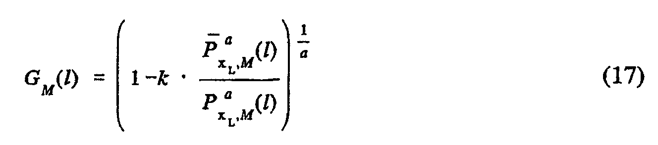
- a and k which control the amount of noise subtraction and speech quality.
- the second parameter k is adjusted so that the desired noise reduction is achieved. For example, if a larger k is chosen, the speech distortion increases.
- the parameter k is typically set depending upon how the first parameter a is chosen. A decrease in a typically leads to a decrease in the k parameter as well in order to keep the speech distortion low. In the case of power spectral subtraction, it is common to use over-subtraction (i.e., k > 1).
- the conventional spectral subtraction gain function (see equation (12)) is derived from a full block estimate and has zero phase.
- the corresponding impulse response g N (u) is non-causal and has length N (equal to the block length). Therefore, the multiplication of the gain function G N (l) and the input signal X N (see equation (11)) results in a periodic circular convolution with a non-causal filter.
- periodic circular convolution can lead to undesirable aliasing in the time domain, and the non-causal nature of the filter can lead to discontinuities between blocks and thus to inferior speech quality.
- the present invention provides methods and apparatuses for providing correct convolution with a causal gain filter and thereby eliminates the above described problems of time domain aliasing and inter-block discontinuity.
- the result of the multiplication is not a correct convolution. Rather, the result is a circular convolution with a periodicity of N: x N N y N where the symbol N ⁇ denotes circular convolution.
- FFT fast Fourier transform
- the accumulated order of the impulse responses x N and y N must be less than or equal to one less than the block length N - 1.
- the time domain aliasing problem resulting from periodic circular convolution can be solved by using a gain function G N ( l ) and an input signal block X N having a total order less than or equal to N - 1.
- the spectrum X N of the input signal is of full block length N.
- an input signal block x L of length L (L ⁇ N) is used to construct a spectrum of order L.
- the length L is called the frame length and thus x L is one frame. Since the spectrum which is multiplied with the gain function of length N should also be of length N, the frame x L is zero padded to the full block length N, resulting in X L ⁇ N .
- the gain function according to the invention can be interpolated from a gain function G M (l) of length M , where M ⁇ N, to form G M ⁇ N ( l ).
- G M ⁇ N ( l ) any known or yet to be developed spectrum estimation technique can be used as an alternative to the above described simple Fourier transform periodogram.
- spectrum estimation techniques provide lower variance in the resulting gain function. See, for example, J.G. Proakis and D.G. Manolakis, Digital Signal Processing; Principles, Algorithms, and Applications, Macmillan , Second Ed., 1992.
- the block of length N is divided into K sub-blocks of length M.
- a periodogram for each sub-block is then computed and the results are averaged to provide an M -long periodogram for the total block as:
- the variance is reduced by a factor K when the sub-blocks are uncorrelated, compared to the full block length periodogram.
- the frequency resolution is also reduced by the same factor.
- the Welch method can be used.
- the Welch method is similar to the Bartlett method except that each sub-block is windowed by a Hanning window, and the sub-blocks are allowed to overlap each other, resulting in more sub-blocks.
- the variance provided by the Welch method is further reduced as compared to the Bartlett method.
- the Bartlett and Welch methods are but two spectral estimation techniques, and other known spectral estimation techniques can be used as well.
- the function P x,M ( l ) is computed using the Bartlett or Welch method, the function P x , M ( l ) is the exponential average for the current block and the function P x , M ( l -1) is the exponential average for the previous block.
- the parameter ⁇ controls how long the exponential memory is, and typically should not exceed the length of how long the noise can be considered stationary. An ⁇ closer to 1 results in a longer exponential memory and a substantial reduction of the periodogram variance.
- the length M is referred to as the sub-block length, and the resulting low order gain function has an impulse response of length M .
- the noise periodogram estimate P x L ,M ( l ) and the noisy speech periodogram estimate P x L ,M ( l ) employed in the composition of the gain function are also of length M :
- this is achieved by using a shorter periodogram estimate from the input frame X L and averaging using, for example, the Bartlett method.
- the Bartlett method (or other suitable estimation method) decreases the variance of the estimated periodogram, and there is also a reduction in frequency resolution.
- the reduction of the resolution from L frequency bins to M bins means that the periodogram estimate P x L ,M ( l ) is also of length M.
- the variance of the noise periodogram estimate P x L ,M ( l ) can be decreased further using exponential averaging as described above.
- the low order filter according to the invention also provides an opportunity to address the problems created by the non-causal nature of the gain filter in the conventional spectral subtraction algorithm (i.e., inter-block discontinuity and diminished speech quality).
- a phase can be added to the gain function to provide a causal filter.
- the phase can be constructed from a magnitude function and can be either linear phase or minimum phase as desired.
- the gain function is also interpolated to a length N, which is done, for example, using a smooth interpolation.
- construction of the linear phase filter can also be performed in the time-domain.
- the gain function G M ( f u ) is transformed to the time-domain using an IFFT, where the circular shift is done.
- the shifted impulse response is zero-padded to a length N , and then transformed back using an N -long FFT. This leads to an interpolated causal linear phase filter G M ⁇ N ( f u ) as desired.
- a causal minimum phase filter according to the invention can be constructed from the gain function by employing a Hilbert transform relation.
- the Hilbert transform relation implies a unique relationship between real and imaginary parts of a complex function.
- this can also be utilized for a relationship between magnitude and phase, when the logarithm of the complex signal is used, as:
- phase is zero, resulting in a real function.
- ) is transformed to the time-domain employing an IFFT of length M, forming g M (n) .
- the time-domain function is rearranged as:
- the function g M ( n ) is transformed back to the frequency-domain using an M-long FFT, yielding ln(
- the causal minimum phase filter G M ( f u ) is then interpolated to a length N. The interpolation is made the same way as in the linear phase case described above.
- the resulting interpolated filter G M ⁇ N ( f u ) is causal and has approximately minimum phase.
- a spectral subtraction noise reduction processor 300 providing linear convolution and causal-filtering, is shown to include a Bartlett processor 305, a magnitude squared processor 320, a voice activity detector 330, a block-wise averaging processor 340, a low order gain computation processor 350, a gain phase processor 355, an interpolation processor 356, a multiplier 360, an inverse fast Fourier transform processor 370 and an overlap and add processor 380.
- the noisy speech input signal is coupled to an input of the Bartlett processor 305 and to an input of the fast Fourier transform processor 310.
- An output of the Bartlett processor 305 is coupled to an input of the magnitude squared processor 320, and an output of the fast Fourier transform processor 310 is coupled to a first input of the multiplier 360.
- An output of the magnitude squared processor 320 is coupled to a first contact of the switch 325 and to a first input of the low order gain computation processor 350.
- a control output of the voice activity detector 330 is coupled to a throw input of the switch 325, and a second contact of the switch 325 is coupled to an input of the block-wise averaging device 340.
- An output of the block-wise averaging device 340 is coupled to a second input of the low order gain computation processor 350, and an output of the low order gain computation processor 350 is coupled to an input of the gain phase processor 355.
- An output of the gain phase processor 355 is coupled to an input of the interpolation processor 356, and an output of the interpolation processor 356 is coupled to a second input of the multiplier 360.
- An output of the multiplier 360 is coupled to an input of the inverse fast Fourier transform processor 370, and an output of the inverse fast Fourier transform processor 370 is coupled to an input of the overlap and add processor 380.
- An output of the overlap and add processor 380 provides a reduced noise, clean speech output for the exemplary noise reduction processor 300.
- the spectral subtraction noise reduction processor 300 processes the incoming noisy speech signal, using the linear convolution, causal filtering algorithm described above, to provide the clean, reduced-noise speech signal.
- the various components of Figure 3 can be implemented using any known digital signal processing technology, including a general purpose computer, a collection of integrated circuits and/or application specific integrated circuitry (ASIC).
- ASIC application specific integrated circuitry
- the variance of the gain function G M ( l ) of the invention can be decreased still further by way of a controlled exponential gain function averaging scheme according to the invention.
- the averaging is made dependent upon the discrepancy between the current block spectrum P x,M ( l ) and the averaged noise spectrum P x,M ( l ). For example, when there is a small discrepancy, long averaging of the gain function G M ( l ) can be provided, corresponding to a stationary background noise situation. Conversely, when there is a large discrepancy, short averaging or no averaging of the gain function G M ( l ) can be provided, corresponding to situations with speech or highly varying background noise.
- the averaging of the gain function is not increased in direct proportion to decreases in the discrepancy, as doing so introduces an audible shadow voice (since the gain function suited for a speech spectrum would remain for a long period). Instead, the averaging is allowed to increase slowly to provide time for the gain function to adapt to the stationary input.
- the parameter ⁇ in equation (27) is used to ensure that the gain function adapts to the new level, when a transition from a period with high discrepancy between the spectra to a period with low discrepancy appears. As noted above, this is done to prevent shadow voices. According to the exemplary embodiments, the adaption is finished before the increased exponential averaging of the gain function starts due to the decreased level of ⁇ ( l ).
- the above equations can be interpreted for different input signal conditions as follows.
- the variance is reduced.
- the noise spectra has a steady mean value for each frequency, it can be averaged to decrease the variance.
- Noise level changes result in a discrepancy between the averaged noise spectrum P x,M ( l ) and the spectrum for the current block P x,M ( l ).
- the controlled exponential averaging method decreases the gain function averaging until the noise level has stabilized at a new level. This behavior enables handling of the noise level changes and gives a decrease in variance during stationary noise periods and prompt response to noise changes.
- High energy speech often has time-varying spectral peaks.
- the exponential averaging is kept at a minimum during high energy speech periods. Since the discrepancy between the average noise spectrum P x,M ( l ) and the current high energy speech spectrum P x,M ( l ) is large, no exponential averaging of the gain function is performed. During lower energy speech periods, the exponential averaging is used with a short memory depending on the discrepancy between the current low-energy speech spectrum and the averaged noise spectrum. The variance reduction is consequently lower for low-energy speech than during background noise periods, and larger compared to high energy speech periods.
- a spectral subtraction noise reduction processor 400 providing linear convolution, causal-filtering and controlled exponential averaging, is shown to include the Bartlett processor 305, the magnitude squared processor 320, the voice activity detector 330, the block-wise averaging device 340, the low order gain computation processor 350, the gain phase processor 355, the interpolation processor 356, the multiplier 360, the inverse fast Fourier transform processor 370 and the overlap and add processor 380 of the system 300 of Figure 3, as well as an averaging control processor 445, an exponential averaging processor 446 and an optional fixed FIR post filter 465.
- the noisy speech input signal is coupled to an input of the Bartlett processor 305 and to an input of the fast Fourier transform processor 310.
- An output of the Bartlett processor 305 is coupled to an input of the magnitude squared processor 320, and an output of the fast Fourier transform processor 310 is coupled to a first input of the multiplier 360.
- An output of the magnitude squared processor 320 is coupled to a first contact of the switch 325, to a first input of the low order gain computation processor 350 and to a first input of the averaging control processor 445.
- a control output of the voice activity detector 330 is coupled to a throw input of the switch 325, and a second contact of the switch 325 is coupled to an input of the block-wise averaging device 340.
- An output of the block-wise averaging device 340 is coupled to a second input of the low order gain computation processor 350 and to a second input of the averaging controller 445.
- An output of the low order gain computation processor 350 is coupled to a signal input of the exponential averaging processor 446, and an output of the averaging controller 445 is coupled to a control input of the exponential averaging processor 446.
- An output of the exponential averaging processor 446 is coupled to an input of the gain phase processor 355, and an output of the gain phase processor 355 is coupled to an input of the interpolation processor 356.
- An output of the interpolation processor 356 is coupled to a second input of the multiplier 360, and an output of the optional fixed FIR post filter 465 is coupled to a third input of the multiplier 360.
- An output of the multiplier 360 is coupled to an input of the inverse fast Fourier transform processor 370, and an output of the inverse fast Fourier transform processor 370 is coupled to an input of the overlap and add processor 380.
- An output of the overlap and add processor 380 provides a clean speech signal for the exemplary system 400.
- the spectral subtraction noise reduction processor 400 processes the incoming noisy speech signal, using the linear convolution, causal filtering and controlled exponential averaging algorithm described above, to provide the improved, reduced-noise speech signal.
- the various components of Figure 4 can be implemented using any known digital signal processing technology, including a general purpose computer, a collection of integrated circuits and/or application specific integrated circuitry (ASIC).
- ASIC application specific integrated circuitry
- the extra fixed FIR filter 465 of length J ⁇ N - 1 - L - M can be added as shown in Figure 4.
- the post filter 465 is applied by multiplying the interpolated impulse response of the filter with the signal spectrum as shown.
- the interpolation to a length N is performed by zero padding of the filter and employing an N-long FFT.
- This post filter 465 can be used to filter out the telephone bandwidth or a constant tonal component.
- the functionality of the post filter 465 can be included directly within the gain function.
- parameter selection is described hereinafter in the context of a GSM mobile telephone.
- the frame length L is set to 160 samples, which provides 20 ms frames. Other choices of L can be used in other systems. However, it should be noted that an increment in the frame length L corresponds to an increment in delay.
- the sub-block length M e.g., the periodogram length for the Bartlett processor
- M is made small to provide increased variance reduction M . Since an FFT is used to compute the periodograms, the length M can be set conveniently to a power of two.
- the GSM system sample rate is 8000 Hz.
- the present invention utilizes a two microphone system.
- the two microphone system is illustrated in Figure 5, where 582 is a mobile telephone, 584 is a near-mouth microphone, and 586 is a far-mouth microphone.
- 582 is a mobile telephone
- 584 is a near-mouth microphone
- 586 is a far-mouth microphone.
- the far-mouth microphone 586 in addition to picking up the background noise, also picks up the speaker's voice, albeit at a lower level than the near-mouth microphone 584.
- a spectral subtraction stage is used to suppress the speech in the far-mouth microphone 586 signal.
- a rough speech estimate is formed with another spectral subtraction stage from the near-mouth signal.
- a third spectral subtraction stage is used to enhance the near-mouth signal by filtering out the enhanced background noise.
- a potential problem with the above technique is the need to make low variance estimates of the filter, i.e., the gain function, since the speech and noise estimates can only be formed from a short block of data samples.
- the single microphone spectral subtraction algorithm discussed above is used. By doing so, this method reduces the variability of the gain function by using Bartlett's spectrum estimation method to reduce the variance.
- the frequency resolution is also reduced by this method but this property is used to make a causal true linear convolution.
- the variability of the gain function is further reduced by adaptive averaging, controlled by a discrepancy measure between the noise and noisy speech spectrum estimates.
- the continuous signal from the near-mouth microphone 584 where the speech is dominating, x s ( n ); and the continuous signal from the far-mouth microphone 586, where the noise is more dominant, x n ( n ).
- the signal from the near-mouth microphone 584 is provided to an input of a buffer 689 where it is broken down into blocks x s ( i ).
- buffer 689 is also a speech encoder.
- the signal from the far-mouth microphone 586 is provided to an input of a buffer 687 where it is broken down into blocks x n ( i ).
- Both buffers 687 and 689 can also include additional signal processing such as an echo canceller in order to further enhance the performance of the present invention.
- An analog to digital (A/D) converter (not shown) converts an analog signal, derived from the microphones 584, 586, to a digital signal so that it may be processed by the spectral subtraction stages of the present invention.
- the A/D converter may be present either prior to or following the buffers 687, 689.
- the first spectral subtraction stage 601 has as its input, a block of the near-mouth signal, x s ( i ), and an estimate of the noise from the previous frame, Y n ( f,i - 1).
- the estimate of noise from the previous frame is produced by coupling the output of the second spectral subtraction stage 602 to the input of a delay circuit 688.
- the output of the delay circuit 688 is coupled to the first spectral subtraction stage 601.
- This first spectral subtraction stage is used to make a rough estimate of the speech, Y r ( f,i ).
- the output of the first spectral subtraction stage 601 is supplied to the second spectral subtraction stage 602 which uses this estimate ( Y r ( f,i )) and a block of the far-mouth signal, x n ( i ) to estimate the noise spectrum for the current frame, Y n ( f,i ).
- the output of the second spectral subtraction stage 602 is supplied to the third spectral subtraction stage 603 which uses the current noise spectrum estimate, Y n ( f,i ), and a block of the near-mouth signal, x s ( i ), to estimate the noise reduced speech, Y s ( f,i ).
- the output of the third spectral subtraction stage 603 is coupled to an input of the inverse fast Fourier transform processor 670, and an output of the inverse fast Fourier transform processor 670 is coupled to an input of the overlap and add processor 680.
- the output of the overlap and add processor 680 provides a clean speech signal as an output from the exemplary system 600.
- each spectral subtraction stage 601-603 has a parameter which controls the size of the subtraction. This parameter is preferably set differently depending on the input SNR of the microphones and the method of noise reduction being employed.
- a controller 604 is used to dynamically set the parameters for each of the spectral subtraction stages 601-603 for further accuracy in a variable noisy environment.
- the far-mouth microphone signal is used to estimate the noise spectrum which will be subtracted from the near-mouth noisy speech spectrum, performance of the present invention will be increased when the background noise spectrum has the same characteristics in both microphones.
- the background characteristics are different when compared to an omni-directional far-mouth microphone.
- one or both of the microphone signals should be filtered in order to reduce the differences of the spectra.
- the present invention uses the same block of samples as the voice encoder. Thereby, no extra delay is introduced for the buffering of the signal block. The introduced delay is therefore only the computation time of the noise reduction of the present invention plus the group delay of the gain function filtering in the last spectral subtraction stage. As illustrated in the third stage, a minimum phase can be imposed on the amplitude gain function which gives a short delay under the constraint of causal filtering.
- VAD 330 the far-mouth microphone can be used to provide a constant noise signal during both voice and non-voice time periods.
- IFFT 370 and the overlap and add circuit 380 have been moved to the final output stage as illustrated as 670 and 680 in Figure 6.
- spectral subtraction stages used in the dual microphone implementation may each be implemented as depicted in Figure 7.
- a spectral subtraction stage 700 providing linear convolution, causal-filtering and controlled exponential averaging, is shown to include the Bartlett processor 705, the frequency decimator 722, the low order gain computation processor 750, the gain phase processor and the interpolation processor 755/756, and the multiplier 760.
- the noisy speech input signal, X ( ⁇ ) ( i ) is coupled to an input of the Bartlett processor 705 and to an input of the fast Fourier transform processor 710.
- the notation X ( ⁇ ) ( i ) is used to represent X n ( i ) or X s ( i ) which are provided to the inputs of spectral subtraction stages 601-603 as illustrated in Figure 6.
- the amplitude spectrum of the unwanted signal, Y ( ⁇ , N ) ( f,i ), Y ( ⁇ ) ( f,i ) with length N, is coupled to an input of the frequency decimator 722.
- the notation Y ( ⁇ ) ( f,i ) is used to represent Y n ( f,i -1), Y r ( f,i ), or Y n ( f,i ).
- An output of the frequency decimator 722 is the amplitude spectrum of Y ( ⁇ , N ) ( f,i ) having length M , where M ⁇ N.
- the frequency decimator 722 reduces the variance of the output amplitude spectrum as compared to the input amplitude spectrum.
- An amplitude spectrum output of the Bartlett processor 705 and an amplitude spectrum output of the frequency decimator 722 are coupled to inputs of the low order gain computation processor 750.
- the output of the fast Fourier transform processor 710 is coupled to a first input of the multiplier 760.
- the output of the low order gain computation processor 750 is coupled to a signal input of an optional exponential averaging processor 746.
- An output of the exponential averaging processor 746 is coupled to an input of the gain phase and interpolation processor 755/756.
- An output of processor 755/756 is coupled to a second input of the multiplier 760.
- the filtered spectrum Y * ( f,i ) is thus the output of the multiplier 760, where the notation Y * ( f,i ) is used to represent Y r ( f,i ), Y n ( f,i ), or Y s ( f,i ).
- the gain function used in Figure 7 is: where
- the gain function can be optionally adaptively averaged. This gain function corresponds to a non-causal time-variating filter.
- One way to obtain a causal filter is to impose a minimum phase.
- An alternate way of obtaining a causal filter is to impose a linear phase.
- G M ( f,i ) With the same number of FFT bins as the input block X ( ⁇ ), N ( f,i ), the gain function is interpolated, G M ⁇ N ( f,i ).
- the gain function, G M ⁇ N ( f,i ) now corresponds to a causal linear filter with length M.
- the spectral subtraction stage 700 processes the incoming noisy speech signal, using the linear convolution, causal filtering and controlled exponential averaging algorithm described above, to provide the improved, reduced-noise speech signal.
- the various components of Figures 6-7 can be implemented using any known digital signal processing technology, including a general purpose computer, a collection of integrated circuits and/or application specific integrated circuitry (ASIC).
- ASIC application specific integrated circuitry
- k ( ⁇ ) is the subtraction factor controlling the amount of suppression employed for a particular spectral subtraction stage.
- each of the values of k ( ⁇ ) i.e., k 1 , k 2 , k 3 where k 1 is used by spectral subtraction stage 601, k 2 is used by spectral subtraction stage 602, and k 3 is used by spectral subtraction stage 603) is dynamically controlled by the controller 604 to compensate for the dynamic nature of the input signals.
- the controller 604 receives, as an input, the gain functions G 1 and G 2 , from the first and second spectral subtraction stages 601, 602, respectively.
- the controller receives x s ( i ) and x n ( i ) from buffers 689, 687, respectively.
- Each of the first, second, and third spectral subtraction stages receive, as an input, a control signal from the controller indicating the present value of the respective subtraction factor.
- the values of k ( ⁇ ) change according to the sound environment. That is, various factors decide the appropriate level of suppression of the background noise and also compensate for the different energy levels of both the background noise and the speech signal in the two microphone signals.
- the block-wise energy levels in the microphone signals are denoted by p 1,x (i) and p 2,x (i) for the near-mouth microphone 584 and the far-mouth microphone 586 signal, respectively.
- the energy of the speech signal in the near-mouth microphone 584 and the far-mouth microphone 586 signals are respectively denoted by p 1,s(i) and p 2,s (i) and the corresponding background noise signals energy are denoted by p 1,n (i) and p 2,n (i) .
- the subtraction factor is set to the level where the first spectral subtraction function, SS 1 , results in a speech signal with a low noise level.
- the parameter k 1 must also compensate for energy level differences of the background signal in the two microphone signals. When the background energy level in the far-mouth microphone 586 signal is greater than the level in the near-mouth microphone 584, k 1 should decrease, hence k 1 ⁇ p 1, n ( i ) p 2, n ( i ) .
- the second spectral subtraction function, SS 2 is used to enhance the noise signal in the far-mouth microphone 586 signal.
- the subtraction factor k 2 controls how much of the speech signal should be suppressed. Since the speech signal in the near-mouth microphone 584 signal has a higher energy level than in the secondary microphone signal k 2 must compensate for this, hence k 2 ⁇ p 2, s ( i ) p 1, s ( i )
- the resulting noise estimate should contain a highly reduced speech signal, preferably no speech signal at all, since remains of the desired speech signal will be disadvantageous to the speech enhancement procedure and will thus lower the quality of the output.
- the third spectral subtraction function, SS 3 is controlled in a similar manner as SS 1 .
- the first exemplary control procedure makes use of the power or magnitude of the input microphone spectra.
- the parameters p 1, x ( i ), p 2,x ( i ), p 1, s ( i ), p 2, s (i), p 1, n ( i ), and p 2,n ( i ) are defined as above or replaced by the corresponding magnitude estimates.
- This procedure is built on the idea of adjusting the energy levels of the speech and noise by means of the subtraction factors.
- the spectral subtraction equation it is possible to derive suitable factors so the energy in the two microphones is leveled.
- Equation (38) is dependent on the ratio of the noise levels in the two microphone signals. Besides t 1 , equation (38) only compensates for differences in energy between the two microphones. The subtraction factor ( i ) increases during speech periods. This is suitable behavior since a stronger noise reduction is needed during these periods.
- the maximum max k 1 ( i ) is used to prevent the subtraction level during speech periods from becoming too high, and to decrease the fluctuations of the gain function.
- the maximum is set by an offset, r 1 , to the minimum k ⁇ ( i ) found during the last ⁇ 1 frames.
- Parameter ⁇ 1 should be large enough so it will cover part of the last "noise only" period.
- the averaged subtraction factor is then used in the spectral subtraction equation (35) instead of the direct subtraction factor k 1 .
- k ⁇ ( f,i ) is derived in the same way as k ⁇ (i) except that it is calculated for each frequency bin separately followed by a smoothing in frequency.
- k 3 ( f,i ) p 1, x ( f,i )(1 - G 1, M ( f,i )) p 2, x ( f,i ) G 2, M ( f,i ) .
- k3 ( i ) min([ k 3 ( f,i ), k 3 ( f,i -1)..., k 3 ( f,i - ⁇ 3 )]+ r 3 , f ⁇ [0,1,..., M -1] where k ⁇ ( f, i ) is the subtraction factor at discrete frequencies f ⁇ [0, 1,..., M -1].
- p 1, x ( f , i ) and p 2, x ( f, i ) are the power or magnitude of respective input microphone signals at individual frequency bins.
- the transfer function between the two microphone signals is frequency dependent. This frequency dependence is varying over time due to movement of, for example, the mobile phone and how it is held. A frequency dependence can also be used for the two first subtraction factors if desired. However, this increases computational complexity.
- the subtraction factor is calculated in each frequency band, it is smoothed over frequencies to reduce its variability giving where V is the odd length of the rectangular smoothing window and [ f + ⁇ ] M / 0 is an interval restriction of the frequency at 0 respectively M.
- Equation (51) depends on the ratio between the speech levels in the two microphone signals.
- an exponentially averaged subtraction factor is introduced where ⁇ 2 is the exponential averaging constant, max k 2 is the maximum allowed k ⁇ and min k 2 is the minimum allowed k ⁇ .
- the averaged subtraction factor is then used in the spectral subtraction equation (48) instead of the direct subtraction factor k ⁇ .
- An alternative exemplary control procedure makes use of the correlation between the two input microphone signals.
- the input time signal samples are denoted as x 1 (n) and x 2 ( n ) for the near-mouth microphone 584 and far-mouth microphone 596, respectively.
- the correlation between the signals is dependent on the degree of similarity between the signals. Generally, the correlation is higher when the user's voice is present. Point-formed background noise sources may have the same effect on the correlation.
- the parameter U is the set of lags of calculated correlation values and K is the time-window duration in samples.
- the estimated correlation measure is used in the calculation of a new correlation energy measure where ⁇ defines a set of integers.
- the use of the square function, as shown in equation (57) is not essential to the invention; other even functions can alternatively be used on the correlation samples.
- the exponential averaging constant ⁇ is set to correspond to an average over less than 4 frames.
- the parameters r 1 , r 2 and r 3 are additive to the correlation energy measure setting a generally lower or higher level of subtraction.
- the adaptive frame-per-frame calculated subtraction factors k 1 ( i ), k 2 ( i ) and k 3 ( i ) are used in the spectral subtraction equations.
- Another alternative exemplary control procedure uses a fixed level of the subtraction factors. This means that each subtraction factor is set to a level that generally works for a large number of environments.
- subtraction factors can be derived from other data not discussed above.
- the subtraction factors can be dynamically generated from information derived from the two input microphone signals.
- information for dynamically generating the subtraction factors can be obtained from other sensors, such as those associated with a vehicle hands free accessory, an office hands free-kit, or a portable hands free cable.
- Still other sources of information for generating the subtraction factors include, but are not limited to, sensors for measuring the distance to the user, and information derived from user or device settings.
- the present invention provides improved methods and apparatuses for dual microphone spectral subtraction using linear convolution, causal filtering and/or controlled exponential averaging of the gain function.
- the present invention can enhance the quality of any audio signal such as music, and the like, and is not limited to only voice or speech audio signals.
- the exemplary methods handle non-stationary background noises, since the present invention does not rely on measuring the noise on only noise-only periods.
- the speech quality is also improved since background noise can be estimated during both noise-only and speech periods.
- the present invention can be used with or without directional microphones, and each microphone can be of a different type.
- the magnitude of the noise reduction can be adjusted to an appropriate level to adjust for a particular desired speech quality.
Abstract
Description


Claims (60)
- A noise reduction system (600), comprising:a first spectral subtraction processor (601) configured to filter a first signal to provide a first noise reduced output signal, wherein an amount of subtraction performed by the first spectral subtraction processor is controlled by a first subtraction factor, k 1;a second spectral subtraction processor (602) configured to filter a second signal as a function of said first noise reduced output signal, to provide a noise estimate output signal, wherein an amount of subtraction performed by the second spectral subtraction processor is controlled by a second subtraction factor, k 2;a third spectral subtraction processor (603) configured to filter said first signal as a function of said noise estimate output signal, wherein an amount of subtraction performed by the third spectral subtraction processor is controlled by a third subtraction factor, k 3; anda controller (604) for dynamically determining at least one of k 1, k 2 and k 3, during operation of the noise reduction system (600).
- The noise reduction system (600) of claim 1, wherein the controller (604) estimates a correlation between the first signal and the second signal.
- The noise reduction system (600) of claim 2, wherein the controller (604) derives at least one of the first, second, and third subtraction factors, k 1, k 2 and k 3, based on the correlation between the first signal and the second signal.
- The noise reduction system (600) of claim 2, wherein the controller (604) estimates a set of correlation samples of the first signal and the second signal and computes a correlation measurement as a sum of squares of the set of correlation samples.
- The noise reduction system (600) of claim 2, wherein the controller (604) estimates a set of correlation samples of the first signal and the second signal and computes a correlation measurement as a sum of an even function of the set of correlation samples.
- The noise reduction system (600) of claim 4, wherein at least one of the subtraction factors, k 1, k 2 and k 3, is derived from the correlation measurement of the set of correlation samples.
- The noise reduction system (600) of claim 5, wherein at least one of the subtraction factors, k 1, k 2 and k 3, is derived from the correlation measurement of the set of correlation samples.
- The noise reduction system (600) of claim 3, wherein at least one of the subtraction factors, k 1, k 2 and k 3, is smoothed over time.
- The noise reduction system (600) of claim 6, wherein at least one of the subtraction factors, k 1, k 2 and k 3, is smoothed over time.
- The noise reduction system (600) of claim 7, wherein at least one of the subtraction factors, k 1, k 2 and k 3, is smoothed over time.
- The noise reduction system (600) of claim 2, wherein k 1, k 2 and k 3, are derived as
γ (i) is an averaged square correlation sum of the first signal and the second signal. - The noise reduction system (600) of claim 1, wherein the controller (604) substantially equalizes energy levels of the first signal and the second signal.
- The noise reduction system (600) of claim 1, wherein the controller (604) substantially equalizes magnitude levels of the first signal and the second signal.
- The noise reduction system (600) of claim 1, wherein the controller (604) derives at least one of the first, second and third subtraction factors from a ratio of noise signal measurement of the first signal and a noise signal measurement of the second signal.
- The noise reduction system (600) of claim 1, wherein the controller (604) derives at least one of the first, second and third subtraction factors from a ratio of desired signal measurement of the second signal and the desired signal measurement of the first signal.
- The noise reduction system (600) of claim 14, wherein each of the noise signal measurements is an energy measurement.
- The noise reduction system (600) of claim 14, wherein each of the noise signal measurements is a magnitude measurement.
- The noise reduction system (600) of claim 15, wherein each of the desired signal measurements is an energy measurement.
- The noise reduction system (600) of claim 15, wherein each of the desired signal measurements is a magnitude measurement.
- The noise reduction system (600) of claim 15, wherein the desired signal is a speech signal.
- The noise reduction system (600) of claim 14, wherein the controller (604) computes at least one of a first relative positive measurement based on a first gain function and a second relative positive measurement based on a second gain function.
- The noise reduction system (600) of claim 15, wherein the controller (604) computes at least one of a first relative positive measurement based on a first gain function, and a second relative positive measurement based on a second gain function.
- The noise reduction system (600) of claim 21, wherein the noise signal measurement is derived from at least one of the first signal and the second signal, and at least one of the first relative positive measurement and the second relative positive measurement, respectively.
- The noise reduction system (600) of claim 22, wherein the desired signal measurement is derived from at least one of the first signal and the second signal, and at least one of the first relative positive measurement and the second relative positive measurement, respectively.
- The noise reduction system (600) of claim 14, wherein a frequency dependent weighting function, performed by at least one of the first and second spectral subtraction processors (601, 602), is used to derive at least one of a first and second frequency dependent positive measurement.
- The noise reduction system (600) of claim 15, wherein a frequency dependent weighting function, performed by at least one of the first and second spectral subtraction processors (601, 602), is used to derive at least one of a first and second frequency dependent positive measurement.
- The noise reduction system (600) of claim 25, wherein the noise signal measurement is derived from at least one of the first signal and the second signal, and at least one of the first frequency dependent positive measurement and the second frequency dependent positive measurement.
- The noise reduction system (600) of claim 26, wherein the noise signal measurement is derived from at least one of the first signal and the second signal, and at least one of the first frequency dependent positive measurement and the second frequency dependent positive measurement.
- The noise reduction system (600) of claim 14, wherein k 1, k 2 and k 3, are derived as:
 where p 1, x (i) is an energy level of the first signal and p 2, x (i) is an energy level of the second signal, t1, t2, t3 are scalar multiplication factors, G 1 is a first gain function, and G 2 is a second gain function.
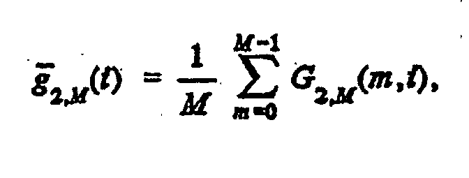
- The noise reduction system (600) of claim 15, wherein k 1, k 2 and k 3, are derived as:
 wherein p 1,x(i) is a magnitude of the first signal and p 2, x (i) is a magnitude level of the second signal, t 1, t 2, t 3 are scalar multiplication factors, G 1 is a first gain function, and G 2 is a second gain function.
- A method for processing a noisy inputsignal and a noise signal to provide a noise reduced output signal, comprising the steps of:wherein at least one of the first, second, and third subtraction factors is dynamically determined during the processing of the noisy input signal and the noise signal.(a) using spectral subtraction to filter said noisy input signal to provide a first noise reduced output signal, wherein an amount of subtraction performed is controlled by a first subtraction factor, k 1;(b) using spectral subtraction to filter said noise signal as a function of said first noise reduced output signal to provide a noise estimate output signal, wherein an amount of subtraction performed is controlled by a second subtraction factor, k 2; and(c) using spectral subtraction to filter said noisy input signal as a function of said noise estimate output signal, wherein an amount of subtraction is controlled by a third subtraction factor, k 3,
- The method of claim 31, wherein a correlation between the first signal and the second signal is estimated.
- The method of claim 32, wherein at least one of the first, second, and third subtraction factors, k 1, k 2, and k 3, is based on the correlation between the first signal and the second signal.
- The method of claim 32, wherein a set of correlation samples of the first signal and the second signal are estimated and correlation measurement as a sum of squares of the set of correlation samples is computed.
- The method of claim 32, wherein a set of correlation samples of the first signal and the second signal are estimated and a correlation measurement as a sum of an even function of the set of correlation samples is computed.
- The method of claim 34, wherein at least one of the subtraction factors, k 1, k 2, and k 3, is derived from the correlation measurement of the set of correlation samples.
- The method of claim 35, wherein at least one of the subtraction factors, k 1, k 2, and k 3, is derived from the correlation measurement of the set of correlation samples.
- The method of claim 33, wherein at least one of the subtraction factors, k 1, k 2, and k 3, is smoothed over time.
- The method of claim 36, wherein at least one of the subtraction factors, k 1, k 2, and k 3, is smoothed over time.
- The method of claim 37, wherein at least one of the subtraction factions, k 1, k 2, k 3, is smoother over time.
- The method of claim 32, wherein k 1, k 2, and k 3 are derived as
γ (i) is an averaged squared correlation sum of the first signal and the second signal. - The method of claim 31, wherein energy levels of the first signal and the second signal are substantially equalized.
- The method of claim 31, wherein magnitude levels of the first signal and the second signal are substantially equalized.
- The method of claim 31, wherein at least one of the first, second, and third subtraction factors is derived from a ratio of noise signal measurement of the first signal and a noise signal measurement of the second signal.
- The method of claim 31, wherein at least one of the first, second, and third subtraction factors is derived from a ratio of desired signal measurement of the second signal and the desired signal measurement of the first signal.
- The method of claim 44, wherein each of the noise signal measurements is an energy measurement.
- The method of claim 44, wherein each of the noise signal measurements is a magnitude measurement.
- The method of claim 45, wherein each of the desired signal measurements is an energy measurement.
- The method of claim 45, wherein each of the desired signal measurements is a magnitude measurement.
- The method of claim 45, wherein the desired signal is a speech signal.
- The method of claim 45, wherein at least one of a first relative positive measurement based on a first gain function and a second relative positive measurement based on a second gain function is computed.
- The method of claim 46, wherein at least one of a first relative positive measurement based on a first gain function and a second relative positive measurement based on a second gain computed.
- The method of clam 51, wherein the noise signal measurement is derived from at least one of the first signal and the second signal, and at least one of the first relative positive measurement and the second relative positive measurement, respectively.
- The method of claim 52, wherein the desired signal measurement is derived from at least one of the first signal and the second signal, and at least one of the first relative positive measurement and the second relative positive measurement, respectively.
- The method of claim 44, wherein a frequency clepeudent weighting function is used to derive at least one of a first and second frequency dependent positive measurement.
- The method of claim 45, wherein a frequency dependent weighting function is used to derive at least one of a first and second frequency dependent positive measurement.
- The method of claim 55, wherein the noise signal measurement is derived from at least one of the first signal and the second signal, and at least one of the first frequency dependent positive measurement and the second frequency dependent positive measurement.
- The method of claim 56, wherein the noise signal measurement is derived from at least one of the first signal and the second signal, and at least one of the first frequency dependent positive measurement and the second frequency dependent positive measurement.
- The method of claim 44, wherein k 1, k 2, and k 3 are derived as:
 where p 1, x (i) is an energy level of the first signal and p 2, x (i) is an energy level of the second signal, t1 , t2, t3 are scalar multiplication factors, G 1 is a first gain function and G 2 is a second gain function.
- The method of claim 45, wherein k 1, k 2, and k 3 are derived as:
 where p 1, x (i) is a magnitude of the first signal and p 2, x (i) is a magnitude level of the second signal, t1, t2, t3 are scalar multiplication factors, G 1 is a first gain function and G 2 is a second gain function.
Applications Claiming Priority (3)
| Application Number | Priority Date | Filing Date | Title |
|---|---|---|---|
| US493265 | 1995-06-21 | ||
| US09/493,265 US6717991B1 (en) | 1998-05-27 | 2000-01-28 | System and method for dual microphone signal noise reduction using spectral subtraction |
| PCT/EP2001/000468 WO2001056328A1 (en) | 2000-01-28 | 2001-01-16 | System and method for dual microphone signal noise reduction using spectral subtraction |
Publications (2)
| Publication Number | Publication Date |
|---|---|
| EP1252796A1 EP1252796A1 (en) | 2002-10-30 |
| EP1252796B1 true EP1252796B1 (en) | 2003-07-23 |
Family
ID=23959535
Family Applications (1)
| Application Number | Title | Priority Date | Filing Date |
|---|---|---|---|
| EP01900464A Expired - Lifetime EP1252796B1 (en) | 2000-01-28 | 2001-01-16 | System and method for dual microphone signal noise reduction using spectral subtraction |
Country Status (8)
| Country | Link |
|---|---|
| US (1) | US6717991B1 (en) |
| EP (1) | EP1252796B1 (en) |
| CN (1) | CN1193644C (en) |
| AT (1) | ATE245884T1 (en) |
| AU (1) | AU2001225171A1 (en) |
| DE (1) | DE60100502D1 (en) |
| MY (1) | MY124883A (en) |
| WO (1) | WO2001056328A1 (en) |
Families Citing this family (101)
| Publication number | Priority date | Publication date | Assignee | Title |
|---|---|---|---|---|
| FR2797343B1 (en) * | 1999-08-04 | 2001-10-05 | Matra Nortel Communications | VOICE ACTIVITY DETECTION METHOD AND DEVICE |
| US6675027B1 (en) * | 1999-11-22 | 2004-01-06 | Microsoft Corp | Personal mobile computing device having antenna microphone for improved speech recognition |
| ATE278970T1 (en) * | 2000-04-25 | 2004-10-15 | Eskom | LOW NOISE SIGNAL EVALUATION |
| WO2001087011A2 (en) * | 2000-05-10 | 2001-11-15 | The Board Of Trustees Of The University Of Illinois | Interference suppression techniques |
| US8019091B2 (en) | 2000-07-19 | 2011-09-13 | Aliphcom, Inc. | Voice activity detector (VAD) -based multiple-microphone acoustic noise suppression |
| US8280072B2 (en) | 2003-03-27 | 2012-10-02 | Aliphcom, Inc. | Microphone array with rear venting |
| US20020054685A1 (en) * | 2000-11-09 | 2002-05-09 | Carlos Avendano | System for suppressing acoustic echoes and interferences in multi-channel audio systems |
| DE10118653C2 (en) * | 2001-04-14 | 2003-03-27 | Daimler Chrysler Ag | Method for noise reduction |
| US8452023B2 (en) | 2007-05-25 | 2013-05-28 | Aliphcom | Wind suppression/replacement component for use with electronic systems |
| US6952482B2 (en) * | 2001-10-02 | 2005-10-04 | Siemens Corporation Research, Inc. | Method and apparatus for noise filtering |
| US7315623B2 (en) * | 2001-12-04 | 2008-01-01 | Harman Becker Automotive Systems Gmbh | Method for supressing surrounding noise in a hands-free device and hands-free device |
| AU2003210111A1 (en) * | 2002-01-07 | 2003-07-24 | Ronald L. Meyer | Microphone support system |
| WO2007059255A1 (en) * | 2005-11-17 | 2007-05-24 | Mh Acoustics, Llc | Dual-microphone spatial noise suppression |
| US8098844B2 (en) | 2002-02-05 | 2012-01-17 | Mh Acoustics, Llc | Dual-microphone spatial noise suppression |
| GB2394391B (en) * | 2002-10-17 | 2006-04-12 | Nec Technologies | A system for reducing the background noise on a telecommunication transmission |
| US9066186B2 (en) | 2003-01-30 | 2015-06-23 | Aliphcom | Light-based detection for acoustic applications |
| US9099094B2 (en) | 2003-03-27 | 2015-08-04 | Aliphcom | Microphone array with rear venting |
| EP1614322A2 (en) * | 2003-04-08 | 2006-01-11 | Philips Intellectual Property & Standards GmbH | Method and apparatus for reducing an interference noise signal fraction in a microphone signal |
| US20050033571A1 (en) * | 2003-08-07 | 2005-02-10 | Microsoft Corporation | Head mounted multi-sensory audio input system |
| US7383181B2 (en) * | 2003-07-29 | 2008-06-03 | Microsoft Corporation | Multi-sensory speech detection system |
| WO2005024787A1 (en) * | 2003-09-02 | 2005-03-17 | Nec Corporation | Signal processing method and apparatus |
| US7162212B2 (en) * | 2003-09-22 | 2007-01-09 | Agere Systems Inc. | System and method for obscuring unwanted ambient noise and handset and central office equipment incorporating the same |
| US7447630B2 (en) * | 2003-11-26 | 2008-11-04 | Microsoft Corporation | Method and apparatus for multi-sensory speech enhancement |
| US7433475B2 (en) * | 2003-11-27 | 2008-10-07 | Canon Kabushiki Kaisha | Electronic device, video camera apparatus, and control method therefor |
| US20050136848A1 (en) * | 2003-12-22 | 2005-06-23 | Matt Murray | Multi-mode audio processors and methods of operating the same |
| US7499686B2 (en) * | 2004-02-24 | 2009-03-03 | Microsoft Corporation | Method and apparatus for multi-sensory speech enhancement on a mobile device |
| US20050239516A1 (en) * | 2004-04-27 | 2005-10-27 | Clarity Technologies, Inc. | Multi-microphone system for a handheld device |
| US20060056645A1 (en) * | 2004-09-01 | 2006-03-16 | Wallis David E | Construction of certain continuous signals from digital samples of a given signal |
| US7574008B2 (en) * | 2004-09-17 | 2009-08-11 | Microsoft Corporation | Method and apparatus for multi-sensory speech enhancement |
| US20060135085A1 (en) * | 2004-12-22 | 2006-06-22 | Broadcom Corporation | Wireless telephone with uni-directional and omni-directional microphones |
| US20060133621A1 (en) * | 2004-12-22 | 2006-06-22 | Broadcom Corporation | Wireless telephone having multiple microphones |
| US7983720B2 (en) * | 2004-12-22 | 2011-07-19 | Broadcom Corporation | Wireless telephone with adaptive microphone array |
| US20060147063A1 (en) * | 2004-12-22 | 2006-07-06 | Broadcom Corporation | Echo cancellation in telephones with multiple microphones |
| US8509703B2 (en) * | 2004-12-22 | 2013-08-13 | Broadcom Corporation | Wireless telephone with multiple microphones and multiple description transmission |
| US20070116300A1 (en) * | 2004-12-22 | 2007-05-24 | Broadcom Corporation | Channel decoding for wireless telephones with multiple microphones and multiple description transmission |
| US7346504B2 (en) * | 2005-06-20 | 2008-03-18 | Microsoft Corporation | Multi-sensory speech enhancement using a clean speech prior |
| US20070036342A1 (en) * | 2005-08-05 | 2007-02-15 | Boillot Marc A | Method and system for operation of a voice activity detector |
| DE102005039621A1 (en) * | 2005-08-19 | 2007-03-01 | Micronas Gmbh | Method and apparatus for the adaptive reduction of noise and background signals in a speech processing system |
| WO2007026827A1 (en) * | 2005-09-02 | 2007-03-08 | Japan Advanced Institute Of Science And Technology | Post filter for microphone array |
| EP1941492A1 (en) * | 2005-10-25 | 2008-07-09 | Anocsys AG | Method for the estimation of a useful signal with the aid of an adaptive process |
| KR100751927B1 (en) * | 2005-11-11 | 2007-08-24 | 고려대학교 산학협력단 | Preprocessing method and apparatus for adaptively removing noise of speech signal on multi speech channel |
| US8345890B2 (en) * | 2006-01-05 | 2013-01-01 | Audience, Inc. | System and method for utilizing inter-microphone level differences for speech enhancement |
| US8744844B2 (en) | 2007-07-06 | 2014-06-03 | Audience, Inc. | System and method for adaptive intelligent noise suppression |
| US8204252B1 (en) | 2006-10-10 | 2012-06-19 | Audience, Inc. | System and method for providing close microphone adaptive array processing |
| US9185487B2 (en) | 2006-01-30 | 2015-11-10 | Audience, Inc. | System and method for providing noise suppression utilizing null processing noise subtraction |
| US8194880B2 (en) * | 2006-01-30 | 2012-06-05 | Audience, Inc. | System and method for utilizing omni-directional microphones for speech enhancement |
| EP1994788B1 (en) | 2006-03-10 | 2014-05-07 | MH Acoustics, LLC | Noise-reducing directional microphone array |
| US20070237338A1 (en) * | 2006-04-11 | 2007-10-11 | Alon Konchitsky | Method and apparatus to improve voice quality of cellular calls by noise reduction using a microphone receiving noise and speech from two air pipes |
| US20070213010A1 (en) * | 2006-03-13 | 2007-09-13 | Alon Konchitsky | System, device, database and method for increasing the capacity and call volume of a communications network |
| US20070237339A1 (en) * | 2006-04-11 | 2007-10-11 | Alon Konchitsky | Environmental noise reduction and cancellation for a voice over internet packets (VOIP) communication device |
| US20070263847A1 (en) * | 2006-04-11 | 2007-11-15 | Alon Konchitsky | Environmental noise reduction and cancellation for a cellular telephone communication device |
| US20070237341A1 (en) * | 2006-04-05 | 2007-10-11 | Creative Technology Ltd | Frequency domain noise attenuation utilizing two transducers |
| GB2437772B8 (en) * | 2006-04-12 | 2008-09-17 | Wolfson Microelectronics Plc | Digital circuit arrangements for ambient noise-reduction. |
| US8150065B2 (en) | 2006-05-25 | 2012-04-03 | Audience, Inc. | System and method for processing an audio signal |
| US8949120B1 (en) | 2006-05-25 | 2015-02-03 | Audience, Inc. | Adaptive noise cancelation |
| US8849231B1 (en) | 2007-08-08 | 2014-09-30 | Audience, Inc. | System and method for adaptive power control |
| US8204253B1 (en) | 2008-06-30 | 2012-06-19 | Audience, Inc. | Self calibration of audio device |
| US8934641B2 (en) * | 2006-05-25 | 2015-01-13 | Audience, Inc. | Systems and methods for reconstructing decomposed audio signals |
| US8259926B1 (en) | 2007-02-23 | 2012-09-04 | Audience, Inc. | System and method for 2-channel and 3-channel acoustic echo cancellation |
| JP4847590B2 (en) * | 2007-04-10 | 2011-12-28 | エスケーテレコム株式会社 | Voice processing apparatus and method in mobile communication terminal |
| US8189766B1 (en) | 2007-07-26 | 2012-05-29 | Audience, Inc. | System and method for blind subband acoustic echo cancellation postfiltering |
| EP2058803B1 (en) | 2007-10-29 | 2010-01-20 | Harman/Becker Automotive Systems GmbH | Partial speech reconstruction |
| US8428661B2 (en) * | 2007-10-30 | 2013-04-23 | Broadcom Corporation | Speech intelligibility in telephones with multiple microphones |
| US8143620B1 (en) | 2007-12-21 | 2012-03-27 | Audience, Inc. | System and method for adaptive classification of audio sources |
| US8180064B1 (en) | 2007-12-21 | 2012-05-15 | Audience, Inc. | System and method for providing voice equalization |
| US8483854B2 (en) * | 2008-01-28 | 2013-07-09 | Qualcomm Incorporated | Systems, methods, and apparatus for context processing using multiple microphones |
| US8194882B2 (en) | 2008-02-29 | 2012-06-05 | Audience, Inc. | System and method for providing single microphone noise suppression fallback |
| US8355511B2 (en) | 2008-03-18 | 2013-01-15 | Audience, Inc. | System and method for envelope-based acoustic echo cancellation |
| JP2009229899A (en) * | 2008-03-24 | 2009-10-08 | Toshiba Corp | Device and method for voice recognition |
| US8521530B1 (en) | 2008-06-30 | 2013-08-27 | Audience, Inc. | System and method for enhancing a monaural audio signal |
| US8774423B1 (en) | 2008-06-30 | 2014-07-08 | Audience, Inc. | System and method for controlling adaptivity of signal modification using a phantom coefficient |
| JP2010122617A (en) | 2008-11-21 | 2010-06-03 | Yamaha Corp | Noise gate and sound collecting device |
| US9838784B2 (en) | 2009-12-02 | 2017-12-05 | Knowles Electronics, Llc | Directional audio capture |
| US9008329B1 (en) | 2010-01-26 | 2015-04-14 | Audience, Inc. | Noise reduction using multi-feature cluster tracker |
| US8798290B1 (en) * | 2010-04-21 | 2014-08-05 | Audience, Inc. | Systems and methods for adaptive signal equalization |
| WO2011140110A1 (en) * | 2010-05-03 | 2011-11-10 | Aliphcom, Inc. | Wind suppression/replacement component for use with electronic systems |
| US9558755B1 (en) | 2010-05-20 | 2017-01-31 | Knowles Electronics, Llc | Noise suppression assisted automatic speech recognition |
| CN103238183B (en) * | 2011-01-19 | 2014-06-04 | 三菱电机株式会社 | Noise suppression device |
| US8903722B2 (en) * | 2011-08-29 | 2014-12-02 | Intel Mobile Communications GmbH | Noise reduction for dual-microphone communication devices |
| US8712769B2 (en) * | 2011-12-19 | 2014-04-29 | Continental Automotive Systems, Inc. | Apparatus and method for noise removal by spectral smoothing |
| US9173025B2 (en) | 2012-02-08 | 2015-10-27 | Dolby Laboratories Licensing Corporation | Combined suppression of noise, echo, and out-of-location signals |
| US8712076B2 (en) | 2012-02-08 | 2014-04-29 | Dolby Laboratories Licensing Corporation | Post-processing including median filtering of noise suppression gains |
| CN103366756A (en) * | 2012-03-28 | 2013-10-23 | 联想(北京)有限公司 | Sound signal reception method and device |
| WO2013187932A1 (en) | 2012-06-10 | 2013-12-19 | Nuance Communications, Inc. | Noise dependent signal processing for in-car communication systems with multiple acoustic zones |
| DE202013005408U1 (en) | 2012-06-25 | 2013-10-11 | Lg Electronics Inc. | Microphone mounting arrangement of a mobile terminal |
| DE112012006876B4 (en) | 2012-09-04 | 2021-06-10 | Cerence Operating Company | Method and speech signal processing system for formant-dependent speech signal amplification |
| US9640194B1 (en) | 2012-10-04 | 2017-05-02 | Knowles Electronics, Llc | Noise suppression for speech processing based on machine-learning mask estimation |
| WO2014070139A2 (en) | 2012-10-30 | 2014-05-08 | Nuance Communications, Inc. | Speech enhancement |
| US9536540B2 (en) | 2013-07-19 | 2017-01-03 | Knowles Electronics, Llc | Speech signal separation and synthesis based on auditory scene analysis and speech modeling |
| EP2860544B1 (en) * | 2013-10-08 | 2020-07-22 | Samsung Electronics Co., Ltd | Audio apparatus and method of reducing noise |
| US9742573B2 (en) * | 2013-10-29 | 2017-08-22 | Cisco Technology, Inc. | Method and apparatus for calibrating multiple microphones |
| DE112015003945T5 (en) | 2014-08-28 | 2017-05-11 | Knowles Electronics, Llc | Multi-source noise reduction |
| US9978388B2 (en) | 2014-09-12 | 2018-05-22 | Knowles Electronics, Llc | Systems and methods for restoration of speech components |
| CN107210824A (en) | 2015-01-30 | 2017-09-26 | 美商楼氏电子有限公司 | The environment changing of microphone |
| WO2016173959A1 (en) | 2015-04-28 | 2016-11-03 | Bayer Pharma Aktiengesellschaft | Regorafenib for treating colorectal cancer |
| US10825480B2 (en) * | 2017-05-31 | 2020-11-03 | Apple Inc. | Automatic processing of double-system recording |
| EP4224833A3 (en) | 2018-05-09 | 2023-10-11 | Nureva Inc. | Method and apparatus utilizing residual echo estimate information to derive secondary echo reduction parameters |
| US10699727B2 (en) * | 2018-07-03 | 2020-06-30 | International Business Machines Corporation | Signal adaptive noise filter |
| CN111147983A (en) * | 2018-11-06 | 2020-05-12 | 展讯通信(上海)有限公司 | Loudspeaker control method and device and readable storage medium |
| EP3714689A1 (en) | 2019-03-27 | 2020-09-30 | Bayer Aktiengesellschaft | Apparatus for insect control |
| US10839821B1 (en) * | 2019-07-23 | 2020-11-17 | Bose Corporation | Systems and methods for estimating noise |
Family Cites Families (12)
| Publication number | Priority date | Publication date | Assignee | Title |
|---|---|---|---|---|
| FR2533100B1 (en) | 1982-09-09 | 1986-06-27 | Sintra Alcatel Sa | METHOD AND DEVICE FOR ATTENUATING INTERFERENCE NOISE |
| SG49709A1 (en) * | 1993-02-12 | 1998-06-15 | British Telecomm | Noise reduction |
| US5418857A (en) * | 1993-09-28 | 1995-05-23 | Noise Cancellation Technologies, Inc. | Active control system for noise shaping |
| US5473701A (en) * | 1993-11-05 | 1995-12-05 | At&T Corp. | Adaptive microphone array |
| US5475761A (en) * | 1994-01-31 | 1995-12-12 | Noise Cancellation Technologies, Inc. | Adaptive feedforward and feedback control system |
| JPH07248778A (en) * | 1994-03-09 | 1995-09-26 | Fujitsu Ltd | Method for renewing coefficient of adaptive filter |
| FR2726392B1 (en) * | 1994-10-28 | 1997-01-10 | Alcatel Mobile Comm France | METHOD AND APPARATUS FOR SUPPRESSING NOISE IN A SPEAKING SIGNAL, AND SYSTEM WITH CORRESPONDING ECHO CANCELLATION |
| SE505156C2 (en) | 1995-01-30 | 1997-07-07 | Ericsson Telefon Ab L M | Procedure for noise suppression by spectral subtraction |
| WO1997023068A2 (en) * | 1995-12-15 | 1997-06-26 | Philips Electronic N.V. | An adaptive noise cancelling arrangement, a noise reduction system and a transceiver |
| US5903819A (en) * | 1996-03-13 | 1999-05-11 | Ericsson Inc. | Noise suppressor circuit and associated method for suppressing periodic interference component portions of a communication signal |
| JP2921472B2 (en) | 1996-03-15 | 1999-07-19 | 日本電気株式会社 | Voice and noise elimination device, voice recognition device |
| FR2768547B1 (en) | 1997-09-18 | 1999-11-19 | Matra Communication | METHOD FOR NOISE REDUCTION OF A DIGITAL SPEAKING SIGNAL |
-
2000
- 2000-01-28 US US09/493,265 patent/US6717991B1/en not_active Expired - Lifetime
-
2001
- 2001-01-16 AT AT01900464T patent/ATE245884T1/en not_active IP Right Cessation
- 2001-01-16 DE DE60100502T patent/DE60100502D1/en not_active Expired - Lifetime
- 2001-01-16 WO PCT/EP2001/000468 patent/WO2001056328A1/en active IP Right Grant
- 2001-01-16 EP EP01900464A patent/EP1252796B1/en not_active Expired - Lifetime
- 2001-01-16 CN CNB018070280A patent/CN1193644C/en not_active Expired - Fee Related
- 2001-01-16 AU AU2001225171A patent/AU2001225171A1/en not_active Abandoned
- 2001-01-17 MY MYPI20010216A patent/MY124883A/en unknown
Also Published As
| Publication number | Publication date |
|---|---|
| AU2001225171A1 (en) | 2001-08-07 |
| EP1252796A1 (en) | 2002-10-30 |
| WO2001056328A1 (en) | 2001-08-02 |
| ATE245884T1 (en) | 2003-08-15 |
| CN1193644C (en) | 2005-03-16 |
| US6717991B1 (en) | 2004-04-06 |
| MY124883A (en) | 2006-07-31 |
| CN1419794A (en) | 2003-05-21 |
| DE60100502D1 (en) | 2003-08-28 |
Similar Documents
| Publication | Publication Date | Title |
|---|---|---|
| EP1252796B1 (en) | System and method for dual microphone signal noise reduction using spectral subtraction | |
| EP1169883B1 (en) | System and method for dual microphone signal noise reduction using spectral subtraction | |
| JP4402295B2 (en) | Signal noise reduction by spectral subtraction using linear convolution and causal filtering | |
| US6487257B1 (en) | Signal noise reduction by time-domain spectral subtraction using fixed filters | |
| EP1080463B1 (en) | Signal noise reduction by spectral subtraction using spectrum dependent exponential gain function averaging | |
| US7206418B2 (en) | Noise suppression for a wireless communication device | |
| EP1046273B1 (en) | Methods and apparatus for providing comfort noise in communications systems | |
| JP4423300B2 (en) | Noise suppressor | |
| EP1769492A1 (en) | Comfort noise generator using modified doblinger noise estimate | |
| WO2005109404A2 (en) | Noise suppression based upon bark band weiner filtering and modified doblinger noise estimate | |
| JP2008519553A (en) | Noise reduction and comfort noise gain control using a bark band wine filter and linear attenuation | |
| JP2003500936A (en) | Improving near-end audio signals in echo suppression systems | |
| US6507623B1 (en) | Signal noise reduction by time-domain spectral subtraction | |
| JP2002076998A (en) | Echo and noise cancellor | |
| Gustafsson et al. | Dual-Microphone Spectral Subtraction | |
| JPH0818473A (en) | Mobil radio terminal | |
| Gustafsson | Speech enhancement for mobile communications |
Legal Events
| Date | Code | Title | Description |
|---|---|---|---|
| PUAI | Public reference made under article 153(3) epc to a published international application that has entered the european phase |
Free format text: ORIGINAL CODE: 0009012 |
|
| 17P | Request for examination filed |
Effective date: 20020819 |
|
| AK | Designated contracting states |
Kind code of ref document: A1 Designated state(s): AT BE CH CY DE DK ES FI FR GB GR IE IT LI LU MC NL PT SE TR |
|
| AX | Request for extension of the european patent |
Free format text: AL PAYMENT 20020819;LT PAYMENT 20020819;LV PAYMENT 20020819;MK PAYMENT 20020819;RO PAYMENT 20020819;SI PAYMENT 20020819 |
|
| GRAH | Despatch of communication of intention to grant a patent |
Free format text: ORIGINAL CODE: EPIDOS IGRA |
|
| GRAH | Despatch of communication of intention to grant a patent |
Free format text: ORIGINAL CODE: EPIDOS IGRA |
|
| GRAA | (expected) grant |
Free format text: ORIGINAL CODE: 0009210 |
|
| AK | Designated contracting states |
Designated state(s): AT BE CH CY DE DK ES FI FR GB GR IE IT LI LU MC NL PT SE TR |
|
| AX | Request for extension of the european patent |
Extension state: AL LT LV MK RO SI |
|
| PG25 | Lapsed in a contracting state [announced via postgrant information from national office to epo] |
Ref country code: IT Free format text: LAPSE BECAUSE OF FAILURE TO SUBMIT A TRANSLATION OF THE DESCRIPTION OR TO PAY THE FEE WITHIN THE PRESCRIBED TIME-LIMIT;WARNING: LAPSES OF ITALIAN PATENTS WITH EFFECTIVE DATE BEFORE 2007 MAY HAVE OCCURRED AT ANY TIME BEFORE 2007. THE CORRECT EFFECTIVE DATE MAY BE DIFFERENT FROM THE ONE RECORDED. Effective date: 20030723 Ref country code: LI Free format text: LAPSE BECAUSE OF FAILURE TO SUBMIT A TRANSLATION OF THE DESCRIPTION OR TO PAY THE FEE WITHIN THE PRESCRIBED TIME-LIMIT Effective date: 20030723 Ref country code: FR Free format text: LAPSE BECAUSE OF FAILURE TO SUBMIT A TRANSLATION OF THE DESCRIPTION OR TO PAY THE FEE WITHIN THE PRESCRIBED TIME-LIMIT Effective date: 20030723 Ref country code: AT Free format text: LAPSE BECAUSE OF FAILURE TO SUBMIT A TRANSLATION OF THE DESCRIPTION OR TO PAY THE FEE WITHIN THE PRESCRIBED TIME-LIMIT Effective date: 20030723 Ref country code: FI Free format text: LAPSE BECAUSE OF FAILURE TO SUBMIT A TRANSLATION OF THE DESCRIPTION OR TO PAY THE FEE WITHIN THE PRESCRIBED TIME-LIMIT Effective date: 20030723 Ref country code: NL Free format text: LAPSE BECAUSE OF FAILURE TO SUBMIT A TRANSLATION OF THE DESCRIPTION OR TO PAY THE FEE WITHIN THE PRESCRIBED TIME-LIMIT Effective date: 20030723 Ref country code: BE Free format text: LAPSE BECAUSE OF FAILURE TO SUBMIT A TRANSLATION OF THE DESCRIPTION OR TO PAY THE FEE WITHIN THE PRESCRIBED TIME-LIMIT Effective date: 20030723 Ref country code: CH Free format text: LAPSE BECAUSE OF FAILURE TO SUBMIT A TRANSLATION OF THE DESCRIPTION OR TO PAY THE FEE WITHIN THE PRESCRIBED TIME-LIMIT Effective date: 20030723 Ref country code: CY Free format text: LAPSE BECAUSE OF FAILURE TO SUBMIT A TRANSLATION OF THE DESCRIPTION OR TO PAY THE FEE WITHIN THE PRESCRIBED TIME-LIMIT Effective date: 20030723 Ref country code: TR Free format text: LAPSE BECAUSE OF FAILURE TO SUBMIT A TRANSLATION OF THE DESCRIPTION OR TO PAY THE FEE WITHIN THE PRESCRIBED TIME-LIMIT Effective date: 20030723 |
|
| REG | Reference to a national code |
Ref country code: GB Ref legal event code: FG4D |
|
| REG | Reference to a national code |
Ref country code: CH Ref legal event code: EP |
|
| REG | Reference to a national code |
Ref country code: IE Ref legal event code: FG4D |
|
| REF | Corresponds to: |
Ref document number: 60100502 Country of ref document: DE Date of ref document: 20030828 Kind code of ref document: P |
|
| PG25 | Lapsed in a contracting state [announced via postgrant information from national office to epo] |
Ref country code: SE Free format text: LAPSE BECAUSE OF FAILURE TO SUBMIT A TRANSLATION OF THE DESCRIPTION OR TO PAY THE FEE WITHIN THE PRESCRIBED TIME-LIMIT Effective date: 20031023 Ref country code: GR Free format text: LAPSE BECAUSE OF FAILURE TO SUBMIT A TRANSLATION OF THE DESCRIPTION OR TO PAY THE FEE WITHIN THE PRESCRIBED TIME-LIMIT Effective date: 20031023 Ref country code: DK Free format text: LAPSE BECAUSE OF FAILURE TO SUBMIT A TRANSLATION OF THE DESCRIPTION OR TO PAY THE FEE WITHIN THE PRESCRIBED TIME-LIMIT Effective date: 20031023 |
|
| PG25 | Lapsed in a contracting state [announced via postgrant information from national office to epo] |
Ref country code: DE Free format text: LAPSE BECAUSE OF FAILURE TO SUBMIT A TRANSLATION OF THE DESCRIPTION OR TO PAY THE FEE WITHIN THE PRESCRIBED TIME-LIMIT Effective date: 20031024 |
|
| PG25 | Lapsed in a contracting state [announced via postgrant information from national office to epo] |
Ref country code: ES Free format text: LAPSE BECAUSE OF FAILURE TO SUBMIT A TRANSLATION OF THE DESCRIPTION OR TO PAY THE FEE WITHIN THE PRESCRIBED TIME-LIMIT Effective date: 20031103 |
|
| NLV1 | Nl: lapsed or annulled due to failure to fulfill the requirements of art. 29p and 29m of the patents act | ||
| PG25 | Lapsed in a contracting state [announced via postgrant information from national office to epo] |
Ref country code: PT Free format text: LAPSE BECAUSE OF FAILURE TO SUBMIT A TRANSLATION OF THE DESCRIPTION OR TO PAY THE FEE WITHIN THE PRESCRIBED TIME-LIMIT Effective date: 20031223 |
|
| LTIE | Lt: invalidation of european patent or patent extension |
Effective date: 20030723 |
|
| PG25 | Lapsed in a contracting state [announced via postgrant information from national office to epo] |
Ref country code: LU Free format text: LAPSE BECAUSE OF NON-PAYMENT OF DUE FEES Effective date: 20040116 Ref country code: IE Free format text: LAPSE BECAUSE OF NON-PAYMENT OF DUE FEES Effective date: 20040116 |
|
| PG25 | Lapsed in a contracting state [announced via postgrant information from national office to epo] |
Ref country code: MC Free format text: LAPSE BECAUSE OF NON-PAYMENT OF DUE FEES Effective date: 20040131 |
|
| REG | Reference to a national code |
Ref country code: CH Ref legal event code: PL |
|
| RAP2 | Party data changed (patent owner data changed or rights of a patent transferred) |
Owner name: TELEFONAKTIEBOLAGET LM ERICSSON (PUBL) |
|
| PLBE | No opposition filed within time limit |
Free format text: ORIGINAL CODE: 0009261 |
|
| STAA | Information on the status of an ep patent application or granted ep patent |
Free format text: STATUS: NO OPPOSITION FILED WITHIN TIME LIMIT |
|
| 26N | No opposition filed |
Effective date: 20040426 |
|
| EN | Fr: translation not filed | ||
| REG | Reference to a national code |
Ref country code: IE Ref legal event code: MM4A |
|
| REG | Reference to a national code |
Ref country code: GB Ref legal event code: 732E Free format text: REGISTERED BETWEEN 20161201 AND 20161207 |
|
| PGFP | Annual fee paid to national office [announced via postgrant information from national office to epo] |
Ref country code: GB Payment date: 20171222 Year of fee payment: 18 |
|
| GBPC | Gb: european patent ceased through non-payment of renewal fee |
Effective date: 20190116 |
|
| PG25 | Lapsed in a contracting state [announced via postgrant information from national office to epo] |
Ref country code: GB Free format text: LAPSE BECAUSE OF NON-PAYMENT OF DUE FEES Effective date: 20190116 |