EP1253292A2 - Methods and systems for cooling gas turbine engine airfoils - Google Patents
Methods and systems for cooling gas turbine engine airfoils Download PDFInfo
- Publication number
- EP1253292A2 EP1253292A2 EP02252966A EP02252966A EP1253292A2 EP 1253292 A2 EP1253292 A2 EP 1253292A2 EP 02252966 A EP02252966 A EP 02252966A EP 02252966 A EP02252966 A EP 02252966A EP 1253292 A2 EP1253292 A2 EP 1253292A2
- Authority
- EP
- European Patent Office
- Prior art keywords
- airfoil
- trailing edge
- chamber
- tip region
- region
- Prior art date
- Legal status (The legal status is an assumption and is not a legal conclusion. Google has not performed a legal analysis and makes no representation as to the accuracy of the status listed.)
- Granted
Links
Images
Classifications
-
- F—MECHANICAL ENGINEERING; LIGHTING; HEATING; WEAPONS; BLASTING
- F01—MACHINES OR ENGINES IN GENERAL; ENGINE PLANTS IN GENERAL; STEAM ENGINES
- F01D—NON-POSITIVE DISPLACEMENT MACHINES OR ENGINES, e.g. STEAM TURBINES
- F01D5/00—Blades; Blade-carrying members; Heating, heat-insulating, cooling or antivibration means on the blades or the members
- F01D5/12—Blades
- F01D5/14—Form or construction
- F01D5/20—Specially-shaped blade tips to seal space between tips and stator
-
- F—MECHANICAL ENGINEERING; LIGHTING; HEATING; WEAPONS; BLASTING
- F01—MACHINES OR ENGINES IN GENERAL; ENGINE PLANTS IN GENERAL; STEAM ENGINES
- F01D—NON-POSITIVE DISPLACEMENT MACHINES OR ENGINES, e.g. STEAM TURBINES
- F01D5/00—Blades; Blade-carrying members; Heating, heat-insulating, cooling or antivibration means on the blades or the members
- F01D5/12—Blades
- F01D5/14—Form or construction
- F01D5/18—Hollow blades, i.e. blades with cooling or heating channels or cavities; Heating, heat-insulating or cooling means on blades
- F01D5/186—Film cooling
-
- Y—GENERAL TAGGING OF NEW TECHNOLOGICAL DEVELOPMENTS; GENERAL TAGGING OF CROSS-SECTIONAL TECHNOLOGIES SPANNING OVER SEVERAL SECTIONS OF THE IPC; TECHNICAL SUBJECTS COVERED BY FORMER USPC CROSS-REFERENCE ART COLLECTIONS [XRACs] AND DIGESTS
- Y10—TECHNICAL SUBJECTS COVERED BY FORMER USPC
- Y10T—TECHNICAL SUBJECTS COVERED BY FORMER US CLASSIFICATION
- Y10T29/00—Metal working
- Y10T29/49—Method of mechanical manufacture
- Y10T29/49316—Impeller making
- Y10T29/49336—Blade making
- Y10T29/49339—Hollow blade
- Y10T29/49341—Hollow blade with cooling passage
Definitions
- This invention relates generally to gas turbine engines, and more specifically to rotor blades used with gas turbine engine combustors.
- a gas turbine engine typically includes a core engine having, in serial flow arrangement, a high pressure compressor which compresses airflow entering the engine, a combustor which burns a mixture of fuel and air, and a turbine which includes a plurality of rotor blades that extract rotational energy from airflow exiting the combustor. the burned mixture. Because the turbine is subjected to high temperature airflow exiting the combustor, turbine components are cooled to reduce thermal stresses that may be induced by the high temperature airflow.
- the rotating blades include hollow airfoils that are supplied cooling air through cooling circuits.
- the airfoils include a cooling cavity bounded by sidewalls that define the cooling cavity.
- the sidewalls are fabricated to have a thickness of at least 0.168 inches.
- the cooling cavity is partitioned into cooling chambers that define flow paths for directing the cooling air.
- a plurality of openings are formed along a trailing edge of the airfoil for discharging cooling air from the airfoil cavity. More specifically, an electro-chemical manufacturing (EDM) process is used to extend the openings from the airfoil trailing edge into the airfoil cavity.
- EDM electro-chemical manufacturing
- the thickness of the sidewalls may permit the electrode to inadvertently gouge the sidewall causing an undesirable condition known as trailing edge scarfing.
- trailing edge scarfing the structural integrity of the airfoil may be compromised, and the airfoil may need replacing.
- operation of an airfoil including scarfing may weaken the airfoil reducing a useful life of the rotor blade.
- a gas turbine engine includes rotor blades including an airfoil that facilitates reducing manufacturing losses due to airfoil trailing edge scarfing.
- Each airfoil includes a first and second sidewall connected at a leading edge and a trailing edge.
- the sidewalls define a cooling cavity that includes at least a leading edge chamber bounded by the sidewalls and the airfoil leading edge, and a trailing edge chamber bounded by sidewalls and the airfoil trailing edge.
- the cooling cavity trailing edge chamber includes a tip region, a throat, and a passageway region connected in flow communication such that the throat is between the tip region and the passageway region.
- the tip region is bounded by the airfoil tip and extends divergently from the throat, such that a width of the tip region is greater than a width of the throat.
- an electro-chemical machining (EDM) process is used to form cooling openings that extend between the airfoil trailing edge and the cooling cavity trailing edge chamber.
- EDM electro-chemical machining
- the reduced thickness of the trailing edge chamber tip region facilitates reducing inadvertent gouging of the airfoil, thus preventing scarfing of the airfoil.
- manufacturing losses due to trailing edge scarfing are facilitated to be reduced in a cost-effective and reliable manner.
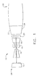
- Figure 1 is a schematic illustration of a gas turbine engine 10 including a fan assembly 12, a high pressure compressor 14, and a combustor 16.
- Engine 10 also includes a high pressure turbine 18, a low pressure turbine 20, and a booster 22.
- Engine 10 has an intake side 28 and an exhaust side 30.
- engine 10 is a CF6 engine commercially available from General Electric Company, Cincinnati, Ohio.
- Airflow from combustor 16 drives turbines 18 and 20, and turbine 20 drives fan assembly 12.
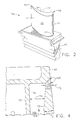
- FIG 2 is a perspective view of a rotor blade 40 that may be used with a gas turbine engine, such as gas turbine engine 10 (shown in Figure 1).
- a gas turbine engine such as gas turbine engine 10 (shown in Figure 1).
- a plurality of rotor blades 40 form a high pressure turbine rotor blade stage (not shown) of gas turbine engine 10.
- Each rotor blade 40 includes a hollow airfoil 42 and an integral dovetail 43 used for mounting airfoil 42 to a rotor disk (not shown) in a known manner.
- blades 40 may extend radially outwardly from an outer rim (not shown), such that a plurality of blades 40 form a blisk (not shown).
- Each airfoil 42 includes a first sidewall 44 and a second sidewall 46.
- First sidewall 44 is convex and defines a suction side of airfoil 42
- second sidewall 46 is concave and defines a pressure side of airfoil 42.
- Sidewalls 44 and 46 are joined at a leading edge 48 and at an axially-spaced trailing edge 50 of airfoil 42. Airfoil trailing edge is spaced chordwise and downstream from airfoil leading edge 48.
- First and second sidewalls 44 and 46 extend longitudinally or radially outward in span from a blade root 52 positioned adjacent dovetail 43 to an airfoil tip 54 which defines a radially outer boundary of an internal cooling chamber (not shown in Figure 2).
- the cooling chamber is bounded within airfoil 42 between sidewalls 44 and 46. More specifically, airfoil 42 includes an inner surface (not shown in Figure 2) and an outer surface 60, and the cooling chamber is defined by the airfoil inner surface.
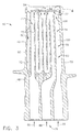
- FIG 3 is a cross-sectional view of blade 40 including airfoil 42.
- Figure 4 is an enlarged view of airfoil 42 taken along area 4 (shown in Figure 3).
- Airfoil 42 includes a cooling cavity 70 defined by an inner surface 72 of airfoil 42.
- Cooling cavity 70 includes a plurality of inner walls 73 which partition cooling cavity 70 into a plurality of cooling chambers 74.
- inner walls 73 are cast integrally with airfoil 42.
- Cooling chambers 74 are supplied cooling air through a plurality of cooling circuits 76.
- airfoil 42 includes a leading edge cooling chamber 80, a trailing edge cooling chamber 82, and a plurality of intermediate cooling chambers 84.
- leading edge cooling chamber 80 is in flow communication with trailing edge and intermediate cooling chambers 82 and 84, respectively.
- Leading edge cooling chamber 80 extends longitudinally or radially through airfoil 42 to airfoil tip 54, and is bordered by airfoil first and second sidewalls 44 and 46, respectively (shown in Figure 2), and by airfoil leading edge 48. Leading edge cooling chamber 80 and an adjacent downstream intermediate cooling chamber 84 are cooled with cooling air supplied by a leading edge cooling circuit 86.
- Intermediate cooling chambers 84 are between leading edge cooling chamber 80 and trailing edge cooling chamber 82, and are supplied cooling air by a mid-circuit cooling circuit 88. More specifically, intermediate cooling chambers 84 are in flow communication and form a serpentine cooling passageway. Intermediate cooling chambers 84 are bordered by bordered by airfoil first and second sidewalls 44 and 46, respectively, and by airfoil tip 54.
- Trailing edge cooling chamber 82 extends longitudinally or radially through airfoil 42 to airfoil tip 54, and is bordered by airfoil first and second sidewalls 44 and 46, respectively, and by airfoil trailing edge 50. Trailing edge cooling chamber 82 is cooled with cooling air supplied by a trailing edge cooling circuit 90. which defines a radially outer boundary of cooling chamber 82. Additionally, trailing edge cooling chamber 82 includes a passageway region 100 and a tip region 102.
- Trailing edge cooling chamber passageway region 100 extends generally convergently from blade root 52 towards airfoil tip 54. More specifically, trailing edge cooling chamber passageway region 100 has an internal width 106 measured between an adjacent inner wall 73 and airfoil inner surface 72. Passageway region width 106 decreases from blade root 52 to a throat 108 located between trailing edge cooling chamber passageway region 100 and tip region 102.
- Trailing edge cooling chamber tip region 102 is bordered by airfoil tip 54 and airfoil trailing edge 50, and is in flow communication with passageway region 100.
- Tip region 102 extends divergently from throat 108 towards airfoil tip 54, such that a width 112 of tip region 102 increases from throat 108 towards airfoil tip 54.
- airfoil inner surface 72 extends radially outwardly towards airfoil outer surface 60.
- a sidewall thickness T 1 within tip region 102 is less than a sidewall thickness T 2 within trailing edge cooling chamber passageway region 100. More specifically, tip region sidewall thickness T 1 is less than 0.168 inches. In the exemplary embodiment, sidewall thickness T 1 is approximately equal 0.108 inches.
- openings 120 extend between airfoil outer surface 60 and airfoil inner surface 72. More specifically, openings 120 extend from airfoil trailing edge 50 towards airfoil leading edge 48, such that each opening 120 is in flow communication with trailing edge cooling chamber tip region 102. Accordingly, openings 120 are known as trailing edge fan holes. In one embodiment, an electro-chemical machining (EDM) process is used to form openings 120.
- EDM electro-chemical machining
- tip region cavity sidewall thickness T 1 is approximately equal 0.108 inches, an EDM electrode (not shown) has a reduced travel distance between airfoil trailing edge 50 and trailing edge cooling chamber tip region 102, in comparison to other known airfoils that do not include trailing edge cooling chamber tip region 102. Accordingly, during the EDM process, thickness T 1 facilitates reducing inadvertent gouging of airfoil 42 by the EDM electrode in an undesirable process known as scarfing. As a result, manufacturing losses due to trailing edge scarfing are facilitated to be reduced. Furthermore, because a contour of airfoil outer surface 60 is not altered to form sidewall thickness T 1 , aerodynamic performance of airfoil 42 is not adversely affected.
- cooling air is supplied into airfoil 42 through cooling circuits 76.
- cooling air is supplied into airfoil 42 from a compressor, such as compressor 14 (shown in Figure 1).
- compressor 14 shown in Figure 1
- the cooling air flows through airfoil 42 and is discharged through tip region openings 120. Because sidewalls 44 and/or 42 bordering trailing edge cooling chamber tip region 102 have thickness T 1 , localized operating temperatures within tip region 102 and in the proximity of openings 120 are facilitated to be reduced, thus increasing a resistance to oxidation within tip region 102.
- the above-described airfoil is cost-effective and highly reliable.
- the airfoil includes a trailing edge cooling chamber that includes a tip region that extends divergently from a passageway region.
- the divergent tip region causes a thickness of bordering sidewalls to be reduced in comparison to a thickness of the sidewalls bordering the remainder of the trailing edge cooling chamber.
- the reduced thickness of the trailing edge tip region facilitates reduced manufacturing losses due to scarfing in a cost-effective and reliable manner.
Abstract
Description
- This invention relates generally to gas turbine engines, and more specifically to rotor blades used with gas turbine engine combustors.
- A gas turbine engine typically includes a core engine having, in serial flow arrangement, a high pressure compressor which compresses airflow entering the engine, a combustor which burns a mixture of fuel and air, and a turbine which includes a plurality of rotor blades that extract rotational energy from airflow exiting the combustor. the burned mixture. Because the turbine is subjected to high temperature airflow exiting the combustor, turbine components are cooled to reduce thermal stresses that may be induced by the high temperature airflow.
- The rotating blades include hollow airfoils that are supplied cooling air through cooling circuits. The airfoils include a cooling cavity bounded by sidewalls that define the cooling cavity. To maintain structural integrity of the airfoil, the sidewalls are fabricated to have a thickness of at least 0.168 inches. The cooling cavity is partitioned into cooling chambers that define flow paths for directing the cooling air.
- During rotor blade manufacture, a plurality of openings are formed along a trailing edge of the airfoil for discharging cooling air from the airfoil cavity. More specifically, an electro-chemical manufacturing (EDM) process is used to extend the openings from the airfoil trailing edge into the airfoil cavity. As the cooling openings are formed with an EDM electrode, the thickness of the sidewalls may permit the electrode to inadvertently gouge the sidewall causing an undesirable condition known as trailing edge scarfing. Depending on the severity of the scarfing, the structural integrity of the airfoil may be compromised, and the airfoil may need replacing. Furthermore, operation of an airfoil including scarfing, may weaken the airfoil reducing a useful life of the rotor blade.
- In an exemplary embodiment, a gas turbine engine includes rotor blades including an airfoil that facilitates reducing manufacturing losses due to airfoil trailing edge scarfing. Each airfoil includes a first and second sidewall connected at a leading edge and a trailing edge. The sidewalls define a cooling cavity that includes at least a leading edge chamber bounded by the sidewalls and the airfoil leading edge, and a trailing edge chamber bounded by sidewalls and the airfoil trailing edge. The cooling cavity trailing edge chamber includes a tip region, a throat, and a passageway region connected in flow communication such that the throat is between the tip region and the passageway region. Furthermore, the tip region is bounded by the airfoil tip and extends divergently from the throat, such that a width of the tip region is greater than a width of the throat.
- During an airfoil manufacturing process, an electro-chemical machining (EDM) process is used to form cooling openings that extend between the airfoil trailing edge and the cooling cavity trailing edge chamber. During the EDM process, the reduced thickness of the trailing edge chamber tip region facilitates reducing inadvertent gouging of the airfoil, thus preventing scarfing of the airfoil. As a result, manufacturing losses due to trailing edge scarfing are facilitated to be reduced in a cost-effective and reliable manner.
- The invention will now be described in greater detail, by way of example, with reference to the drawings, in which:-
- Figure 1 is schematic illustration of a gas turbine engine;
- Figure 2 is a perspective view of an airfoil that may be used with the gas turbine engine shown in Figure 1;
- Figure 3 is a cross sectional view of the airfoil shown in Figure 2; and
- Figure 4 is an enlarged view of the airfoil shown in Figure 3 taken along
area 4. -
- Figure 1 is a schematic illustration of a
gas turbine engine 10 including afan assembly 12, ahigh pressure compressor 14, and acombustor 16.Engine 10 also includes ahigh pressure turbine 18, alow pressure turbine 20, and abooster 22.Engine 10 has anintake side 28 and anexhaust side 30. In one embodiment,engine 10 is a CF6 engine commercially available from General Electric Company, Cincinnati, Ohio. - In operation, air flows through
fan assembly 12 and compressed air is supplied tohigh pressure compressor 14. The highly compressed air is delivered tocombustor 16. Airflow fromcombustor 16drives turbines turbine 20drives fan assembly 12. - Figure 2 is a perspective view of a
rotor blade 40 that may be used with a gas turbine engine, such as gas turbine engine 10 (shown in Figure 1). In one embodiment, a plurality ofrotor blades 40 form a high pressure turbine rotor blade stage (not shown) ofgas turbine engine 10. Eachrotor blade 40 includes ahollow airfoil 42 and anintegral dovetail 43 used for mountingairfoil 42 to a rotor disk (not shown) in a known manner. Alternatively,blades 40 may extend radially outwardly from an outer rim (not shown), such that a plurality ofblades 40 form a blisk (not shown). - Each
airfoil 42 includes afirst sidewall 44 and asecond sidewall 46.First sidewall 44 is convex and defines a suction side ofairfoil 42, andsecond sidewall 46 is concave and defines a pressure side ofairfoil 42.Sidewalls edge 48 and at an axially-spacedtrailing edge 50 ofairfoil 42. Airfoil trailing edge is spaced chordwise and downstream fromairfoil leading edge 48. - First and
second sidewalls blade root 52 positionedadjacent dovetail 43 to anairfoil tip 54 which defines a radially outer boundary of an internal cooling chamber (not shown in Figure 2). The cooling chamber is bounded withinairfoil 42 betweensidewalls airfoil 42 includes an inner surface (not shown in Figure 2) and anouter surface 60, and the cooling chamber is defined by the airfoil inner surface. - Figure 3 is a cross-sectional view of
blade 40 includingairfoil 42. Figure 4 is an enlarged view ofairfoil 42 taken along area 4 (shown in Figure 3). Airfoil 42 includes acooling cavity 70 defined by aninner surface 72 ofairfoil 42.Cooling cavity 70 includes a plurality ofinner walls 73 whichpartition cooling cavity 70 into a plurality ofcooling chambers 74. In one embodiment,inner walls 73 are cast integrally withairfoil 42.Cooling chambers 74 are supplied cooling air through a plurality ofcooling circuits 76. More specifically, airfoil 42 includes a leadingedge cooling chamber 80, a trailingedge cooling chamber 82, and a plurality ofintermediate cooling chambers 84. In one embodiment, leadingedge cooling chamber 80 is in flow communication with trailing edge andintermediate cooling chambers - Leading
edge cooling chamber 80 extends longitudinally or radially throughairfoil 42 toairfoil tip 54, and is bordered by airfoil first andsecond sidewalls airfoil leading edge 48. Leadingedge cooling chamber 80 and an adjacent downstreamintermediate cooling chamber 84 are cooled with cooling air supplied by a leadingedge cooling circuit 86. -
Intermediate cooling chambers 84 are between leadingedge cooling chamber 80 and trailingedge cooling chamber 82, and are supplied cooling air by amid-circuit cooling circuit 88. More specifically,intermediate cooling chambers 84 are in flow communication and form a serpentine cooling passageway.Intermediate cooling chambers 84 are bordered by bordered by airfoil first andsecond sidewalls airfoil tip 54. - Trailing
edge cooling chamber 82 extends longitudinally or radially throughairfoil 42 toairfoil tip 54, and is bordered by airfoil first andsecond sidewalls trailing edge 50. Trailingedge cooling chamber 82 is cooled with cooling air supplied by a trailingedge cooling circuit 90. which defines a radially outer boundary ofcooling chamber 82. Additionally, trailingedge cooling chamber 82 includes apassageway region 100 and atip region 102. - Trailing edge cooling
chamber passageway region 100 extends generally convergently fromblade root 52 towardsairfoil tip 54. More specifically, trailing edge coolingchamber passageway region 100 has an internal width 106 measured between an adjacentinner wall 73 and airfoilinner surface 72. Passageway region width 106 decreases fromblade root 52 to athroat 108 located between trailing edge coolingchamber passageway region 100 andtip region 102. - Trailing edge cooling
chamber tip region 102 is bordered byairfoil tip 54 and airfoiltrailing edge 50, and is in flow communication withpassageway region 100.Tip region 102 extends divergently fromthroat 108 towardsairfoil tip 54, such that awidth 112 oftip region 102 increases fromthroat 108 towardsairfoil tip 54. Furthermore, withintip region 102, airfoilinner surface 72 extends radially outwardly towards airfoilouter surface 60. As a result, a sidewall thickness T1 withintip region 102 is less than a sidewall thickness T2 within trailing edge coolingchamber passageway region 100. More specifically, tip region sidewall thickness T1 is less than 0.168 inches. In the exemplary embodiment, sidewall thickness T1 is approximately equal 0.108 inches. - A plurality of
openings 120 extend between airfoilouter surface 60 and airfoilinner surface 72. More specifically,openings 120 extend fromairfoil trailing edge 50 towardsairfoil leading edge 48, such that eachopening 120 is in flow communication with trailing edge coolingchamber tip region 102. Accordingly,openings 120 are known as trailing edge fan holes. In one embodiment, an electro-chemical machining (EDM) process is used to formopenings 120. - During manufacture of
airfoil 42, because tip region cavity sidewall thickness T1 is approximately equal 0.108 inches, an EDM electrode (not shown) has a reduced travel distance betweenairfoil trailing edge 50 and trailing edge coolingchamber tip region 102, in comparison to other known airfoils that do not include trailing edge coolingchamber tip region 102. Accordingly, during the EDM process, thickness T1 facilitates reducing inadvertent gouging ofairfoil 42 by the EDM electrode in an undesirable process known as scarfing. As a result, manufacturing losses due to trailing edge scarfing are facilitated to be reduced. Furthermore, because a contour of airfoilouter surface 60 is not altered to form sidewall thickness T1, aerodynamic performance ofairfoil 42 is not adversely affected. - During engine operation, cooling air is supplied into
airfoil 42 throughcooling circuits 76. In one embodiment, cooling air is supplied intoairfoil 42 from a compressor, such as compressor 14 (shown in Figure 1). As cooling air enters trailingedge cooling chamber 82 from trailingedge cooling circuit 90, the cooling air flows throughairfoil 42 and is discharged throughtip region openings 120. Becausesidewalls 44 and/or 42 bordering trailing edge coolingchamber tip region 102 have thickness T1, localized operating temperatures withintip region 102 and in the proximity ofopenings 120 are facilitated to be reduced, thus increasing a resistance to oxidation withintip region 102. - The above-described airfoil is cost-effective and highly reliable. The airfoil includes a trailing edge cooling chamber that includes a tip region that extends divergently from a passageway region. The divergent tip region causes a thickness of bordering sidewalls to be reduced in comparison to a thickness of the sidewalls bordering the remainder of the trailing edge cooling chamber. As a result, the reduced thickness of the trailing edge tip region facilitates reduced manufacturing losses due to scarfing in a cost-effective and reliable manner.
- For the sake of good order, various aspects of the invention are set out in the following clauses:-
- 1. A method for manufacturing an airfoil (42) for a gas turbine engine (10)
to facilitate reducing airfoil trailing edge scarfing, said method comprising the
steps of:
- defining a cavity (70) in the airfoil with a wall including a concave portion (46) and a convex portion (44) connected at a leading edge (48) and at a trailing edge (50); and
- dividing the cavity into at least a leading edge chamber (80) and a trailing edge chamber (82), such that the leading edge chamber is bordered by the airfoil leading edge, and the trailing edge chamber is bordered by the trailing edge and includes a tip region (102) and a passageway region (106), wherein the trailing edge chamber tip region extends divergently from the passageway region, such that at least a portion of the wall bordering the tip region has a thickness less than 0.168 inches.
- 2. A method in accordance with Clause 1 further comprising the step of forming a plurality of openings (120) extending through the airfoil wall in flow communication with the cavity trailing edge chamber tip region (102).
- 3. A method in accordance with Clause 3 wherein said step of forming a plurality of openings (120) further comprises the step using an electro-chemical machining (EDM) process to form the openings.
- 4. A method in accordance with Clause 1 wherein said step of dividing the cavity (70) further comprises the step of forming the trailing edge chamber (82) such that the cavity trailing edge chamber tip region (102) extends divergently from the trailing edge chamber passageway (100), wherein at least a portion of the wall bordering the tip region has a thickness approximately equal 0.108 inches.
- 5. A method in accordance with Clause 1 wherein said step of dividing the cavity (70) further comprises the step of casting the airfoil (42) to include at least the cavity leading edge chamber (80) and the cavity trailing edge cavity (82).
- 6. An airfoil (42) for a gas turbine engine (10), said airfoil comprising:
- a leading edge(48);
- a trailing edge (50);
- a first sidewall (44) extending in radial span between an airfoil root (52) and an airfoil tip (54);
- a second sidewall (46) connected to said first sidewall at said leading edge and said trailing edge, said second sidewall extending in radial span between the airfoil root and the airfoil tip, and
- a cooling cavity (70) defined by said first sidewall inner surface and said second sidewall inner surface, said cooling cavity comprising at least a leading edge chamber (80) bounded by said first sidewall, said second sidewall, and said leading edge, and a trailing edge chamber (82) bounded by said first sidewall, said second sidewall, and said trailing edge, said cooling cavity trailing edge chamber comprising a tip region(102), a throat (108), and a passageway region (100), said throat between said tip region and said passageway region, said tip region bounded by the airfoil tip (54) and extending divergently from said throat, such that a width (112) of said tip region is greater than a width of said throat.
- 7. An airfoil (42) in accordance with Clause 6 further comprising an inner surface (72), an outer surface (60), and a plurality of openings (120) extending therebetween into said cooling cavity trailing edge chamber tip region (102).
- 8. An airfoil (42) in accordance with Clause 7 wherein said cooling cavity trailing edge chamber (82) in flow communication with said leading edge chamber (80).
- 9. An airfoil (42) in accordance with Clause 7 wherein said airfoil has a thickness extending between said outer and inner surfaces (60, 72), at least a portion of said airfoil thickness bordering said cooling cavity trailing edge chamber tip region (102) smaller than a thickness of said airfoil bordering said cooling cavity trailing edge chamber throat (108) and said cooling cavity trailing edge passageway region (100).
- 10. An airfoil (42) in accordance with Clause 9 wherein said airfoil thickness bordering said cooling cavity trailing edge chamber tip region (102) configured to facilitate a reduction in localized metal temperature within said airfoil.
- 11. An airfoil (42) in accordance with Clause 9 wherein said airfoil thickness bordering said cooling cavity trailing edge chamber tip region (102) less than 0.168 inches.
- 12. An airfoil (42) in accordance with Clause 9 wherein said airfoil thickness bordering said cooling cavity trailing edge chamber tip region (102) approximately equal 0.108 inches.
- 13. An airfoil (42) in accordance with Clause 9 wherein said airfoil thickness bordering said cooling cavity trailing edge chamber tip region (102) configured to facilitate reducing airfoil trailing edge (50) scarfing.
- 14. A gas turbine engine (10) comprising a plurality of airfoils (42), each said airfoil comprising a leading edge (48), a trailing edge (50), a wall (73), and a cooling cavity (70) defined by said wall, said cooling cavity comprising at least two chambers, a first of said chambers (80) bounded by said leading edge, a second of said chambers (82) bounded by said trailing edge, said second chamber comprising a tip region (102) adjacent said trailing edge, said wall comprising a plurality of openings (120) extending therethrough, such that said openings in flow communication with said cooling chamber second chamber tip region, at least a portion of said wall bordering said tip region having a thickness less than 0.168 inches.
- 15. A gas turbine engine (10) in accordance with
Clause 14 wherein each said airfoil cooling cavity second chamber (82) further comprises a passageway region (100) and a throat (108), said passageway region in flow communication with said tip region (102), said throat between said passageway region and said tip region. - 16. A gas turbine engine (10) in accordance with Clause 15 wherein said airfoil cooling cavity second chamber tip region (102) extends divergently from said throat (108).
- 17. A gas turbine engine (10) in accordance with Clause 15 wherein said airfoil wall (73) bordering said cooling cavity second chamber tip region (102) has a thickness approximately equal 0.108 inches.
- 18. A gas turbine engine (10) in accordance with Clause 15 wherein said airfoil wall (73) bordering said cooling cavity second chamber tip region (102) has a thickness configured to facilitate a reduction in localized metal temperature within said airfoil (42).
- 19. A gas turbine engine (10) in accordance with Clause 15 wherein said airfoil wall (73) bordering said cooling cavity second chamber tip region (102) has a thickness configured to facilitate reducing airfoil trailing edge (50) scarfing.
-
Claims (10)
- A method for manufacturing an airfoil (42) for a gas turbine engine (10) to facilitate reducing airfoil trailing edge scarfing, said method comprising the steps of:defining a cavity (70) in the airfoil with a wall including a concave portion (46) and a convex portion (44) connected at a leading edge (48) and at a trailing edge (50); anddividing the cavity into at least a leading edge chamber (80) and a trailing edge chamber (82), such that the leading edge chamber is bordered by the airfoil leading edge, and the trailing edge chamber is bordered by the trailing edge and includes a tip region (102) and a passageway region (106), wherein the trailing edge chamber tip region extends divergently from the passageway region, such that at least a portion of the wall bordering the tip region has a thickness less than 0.168 inches.
- A method in accordance with Claim 1 further comprising the step of forming a plurality of openings (120) extending through the airfoil wall in flow communication with the cavity trailing edge chamber tip region (102).
- A method in accordance with Claim 3 wherein said step of forming a plurality of openings (120) further comprises the step using an electro-chemical machining (EDM) process to form the openings.
- A method in accordance with Claim 1, 2 or 3 wherein said step of dividing the cavity (70) further comprises the step of forming the trailing edge chamber (82) such that the cavity trailing edge chamber tip region (102) extends divergently from the trailing edge chamber passageway (100), wherein at least a portion of the wall bordering the tip region has a thickness approximately equal 0.108 inches.
- An airfoil (42) for a gas turbine engine (10), said airfoil comprising:a leading edge(48);a trailing edge (50);a first sidewall (44) extending in radial span between an airfoil root (52) and an airfoil tip (54);a second sidewall (46) connected to said first sidewall at said leading edge and said trailing edge, said second sidewall extending in radial span between the airfoil root and the airfoil tip, anda cooling cavity (70) defined by said first sidewall inner surface and said second sidewall inner surface, said cooling cavity comprising at least a leading edge chamber (80) bounded by said first sidewall, said second sidewall, and said leading edge, and a trailing edge chamber (82) bounded by said first sidewall, said second sidewall, and said trailing edge, said cooling cavity trailing edge chamber comprising a tip region(102), a throat (108), and a passageway region (100), said throat between said tip region and said passageway region, said tip region bounded by the airfoil tip (54) and extending divergently from said throat, such that a width (112) of said tip region is greater than a width of said throat.
- An airfoil (42) in accordance with Claim 5 further comprising an inner surface (72), an outer surface (60), and a plurality of openings (120) extending therebetween into said cooling cavity trailing edge chamber tip region (102).
- An airfoil (42) in accordance with Claim 5 or 6 wherein said cooling cavity trailing edge chamber (82) in flow communication with said leading edge chamber (80).
- A gas turbine engine (10) comprising a plurality of airfoils (42), each said airfoil comprising a leading edge (48), a trailing edge (50), a wall (73), and a cooling cavity (70) defined by said wall, said cooling cavity comprising at least two chambers, a first of said chambers (80) bounded by said leading edge, a second of said chambers (82) bounded by said trailing edge, said second chamber comprising a tip region (102) adjacent said trailing edge, said wall comprising a plurality of openings (120) extending therethrough, such that said openings in flow communication with said cooling chamber second chamber tip region, at least a portion of said wall bordering said tip region having a thickness less than 0.168 inches.
- A gas turbine engine (10) in accordance with Claim 8 wherein each said airfoil cooling cavity second chamber (82) further comprises a passageway region (100) and a throat (108), said passageway region in flow communication with said tip region (102), said throat between said passageway region and said tip region.
- A gas turbine engine (10) in accordance with Claim 8 or 9 wherein said airfoil cooling cavity second chamber tip region (102) extends divergently from said throat (108).
Applications Claiming Priority (2)
| Application Number | Priority Date | Filing Date | Title |
|---|---|---|---|
| US09/844,206 US6561758B2 (en) | 2001-04-27 | 2001-04-27 | Methods and systems for cooling gas turbine engine airfoils |
| US844206 | 2001-04-27 |
Publications (3)
| Publication Number | Publication Date |
|---|---|
| EP1253292A2 true EP1253292A2 (en) | 2002-10-30 |
| EP1253292A3 EP1253292A3 (en) | 2004-09-22 |
| EP1253292B1 EP1253292B1 (en) | 2007-07-04 |
Family
ID=25292111
Family Applications (1)
| Application Number | Title | Priority Date | Filing Date |
|---|---|---|---|
| EP02252966A Expired - Fee Related EP1253292B1 (en) | 2001-04-27 | 2002-04-26 | Methods and systems for cooling gas turbine engine airfoils |
Country Status (4)
| Country | Link |
|---|---|
| US (1) | US6561758B2 (en) |
| EP (1) | EP1253292B1 (en) |
| JP (1) | JP4138363B2 (en) |
| DE (1) | DE60220967T2 (en) |
Cited By (2)
| Publication number | Priority date | Publication date | Assignee | Title |
|---|---|---|---|---|
| EP1832712A1 (en) * | 2006-03-08 | 2007-09-12 | Snecma | Turbomachine blade with a cooling air manifold cavity |
| WO2021236073A1 (en) * | 2020-05-20 | 2021-11-25 | Siemens Aktiengesellschaft | Turbine blade |
Families Citing this family (37)
| Publication number | Priority date | Publication date | Assignee | Title |
|---|---|---|---|---|
| US7424021B2 (en) * | 2003-01-31 | 2008-09-09 | Hewlett-Packard Development Company, L.P. | Method and apparatus for processing network topology data |
| US6902372B2 (en) * | 2003-09-04 | 2005-06-07 | Siemens Westinghouse Power Corporation | Cooling system for a turbine blade |
| US7137780B2 (en) * | 2004-06-17 | 2006-11-21 | Siemens Power Generation, Inc. | Internal cooling system for a turbine blade |
| EP1655451B1 (en) * | 2004-11-09 | 2010-06-30 | Rolls-Royce Plc | A cooling arrangement |
| US7300250B2 (en) * | 2005-09-28 | 2007-11-27 | Pratt & Whitney Canada Corp. | Cooled airfoil trailing edge tip exit |
| US7431562B2 (en) * | 2005-12-21 | 2008-10-07 | General Electric Company | Method and apparatus for cooling gas turbine rotor blades |
| US7513738B2 (en) * | 2006-02-15 | 2009-04-07 | General Electric Company | Methods and apparatus for cooling gas turbine rotor blades |
| US7431561B2 (en) * | 2006-02-16 | 2008-10-07 | General Electric Company | Method and apparatus for cooling gas turbine rotor blades |
| US20080085193A1 (en) * | 2006-10-05 | 2008-04-10 | Siemens Power Generation, Inc. | Turbine airfoil cooling system with enhanced tip corner cooling channel |
| US7704046B1 (en) | 2007-05-24 | 2010-04-27 | Florida Turbine Technologies, Inc. | Turbine blade with serpentine cooling circuit |
| US8172506B2 (en) * | 2008-11-26 | 2012-05-08 | General Electric Company | Method and system for cooling engine components |
| US9890647B2 (en) * | 2009-12-29 | 2018-02-13 | Rolls-Royce North American Technologies Inc. | Composite gas turbine engine component |
| US8733111B2 (en) | 2012-02-15 | 2014-05-27 | United Technologies Corporation | Cooling hole with asymmetric diffuser |
| US9410435B2 (en) | 2012-02-15 | 2016-08-09 | United Technologies Corporation | Gas turbine engine component with diffusive cooling hole |
| US8683814B2 (en) | 2012-02-15 | 2014-04-01 | United Technologies Corporation | Gas turbine engine component with impingement and lobed cooling hole |
| US9482100B2 (en) | 2012-02-15 | 2016-11-01 | United Technologies Corporation | Multi-lobed cooling hole |
| US9284844B2 (en) | 2012-02-15 | 2016-03-15 | United Technologies Corporation | Gas turbine engine component with cusped cooling hole |
| US9279330B2 (en) | 2012-02-15 | 2016-03-08 | United Technologies Corporation | Gas turbine engine component with converging/diverging cooling passage |
| US8683813B2 (en) | 2012-02-15 | 2014-04-01 | United Technologies Corporation | Multi-lobed cooling hole and method of manufacture |
| US8689568B2 (en) | 2012-02-15 | 2014-04-08 | United Technologies Corporation | Cooling hole with thermo-mechanical fatigue resistance |
| US9422815B2 (en) | 2012-02-15 | 2016-08-23 | United Technologies Corporation | Gas turbine engine component with compound cusp cooling configuration |
| US9598979B2 (en) | 2012-02-15 | 2017-03-21 | United Technologies Corporation | Manufacturing methods for multi-lobed cooling holes |
| US9024226B2 (en) | 2012-02-15 | 2015-05-05 | United Technologies Corporation | EDM method for multi-lobed cooling hole |
| US8763402B2 (en) | 2012-02-15 | 2014-07-01 | United Technologies Corporation | Multi-lobed cooling hole and method of manufacture |
| US9416971B2 (en) | 2012-02-15 | 2016-08-16 | United Technologies Corporation | Multiple diffusing cooling hole |
| US9273560B2 (en) | 2012-02-15 | 2016-03-01 | United Technologies Corporation | Gas turbine engine component with multi-lobed cooling hole |
| US10422230B2 (en) | 2012-02-15 | 2019-09-24 | United Technologies Corporation | Cooling hole with curved metering section |
| US8850828B2 (en) | 2012-02-15 | 2014-10-07 | United Technologies Corporation | Cooling hole with curved metering section |
| US8584470B2 (en) | 2012-02-15 | 2013-11-19 | United Technologies Corporation | Tri-lobed cooling hole and method of manufacture |
| US8522558B1 (en) | 2012-02-15 | 2013-09-03 | United Technologies Corporation | Multi-lobed cooling hole array |
| US9416665B2 (en) | 2012-02-15 | 2016-08-16 | United Technologies Corporation | Cooling hole with enhanced flow attachment |
| US8572983B2 (en) | 2012-02-15 | 2013-11-05 | United Technologies Corporation | Gas turbine engine component with impingement and diffusive cooling |
| US8707713B2 (en) | 2012-02-15 | 2014-04-29 | United Technologies Corporation | Cooling hole with crenellation features |
| US9810072B2 (en) | 2014-05-28 | 2017-11-07 | General Electric Company | Rotor blade cooling |
| US10605092B2 (en) | 2016-07-11 | 2020-03-31 | United Technologies Corporation | Cooling hole with shaped meter |
| DE102019201085A1 (en) * | 2019-01-29 | 2020-07-30 | Siemens Aktiengesellschaft | Manufacturing process for a component with integrated channels |
| TWI720442B (en) * | 2019-03-20 | 2021-03-01 | 財團法人金屬工業研究發展中心 | Electrochemical processing device of enclosed vane |
Citations (3)
| Publication number | Priority date | Publication date | Assignee | Title |
|---|---|---|---|---|
| US5360957A (en) * | 1992-06-11 | 1994-11-01 | General Electric Company | Controlled apparatus for electrical discharge machining |
| US6019579A (en) * | 1997-03-10 | 2000-02-01 | Mitsubishi Heavy Industries, Ltd. | Gas turbine rotating blade |
| US6036440A (en) * | 1997-04-01 | 2000-03-14 | Mitsubishi Heavy Industries, Ltd. | Gas turbine cooled moving blade |
Family Cites Families (9)
| Publication number | Priority date | Publication date | Assignee | Title |
|---|---|---|---|---|
| US5660524A (en) | 1992-07-13 | 1997-08-26 | General Electric Company | Airfoil blade having a serpentine cooling circuit and impingement cooling |
| US5599166A (en) * | 1994-11-01 | 1997-02-04 | United Technologies Corporation | Core for fabrication of gas turbine engine airfoils |
| US5813118A (en) | 1997-06-23 | 1998-09-29 | General Electric Company | Method for repairing an air cooled turbine engine airfoil |
| US6220817B1 (en) | 1997-11-17 | 2001-04-24 | General Electric Company | AFT flowing multi-tier airfoil cooling circuit |
| US5975851A (en) * | 1997-12-17 | 1999-11-02 | United Technologies Corporation | Turbine blade with trailing edge root section cooling |
| US6183811B1 (en) | 1998-12-15 | 2001-02-06 | General Electric Company | Method of repairing turbine airfoils |
| US6206638B1 (en) | 1999-02-12 | 2001-03-27 | General Electric Company | Low cost airfoil cooling circuit with sidewall impingement cooling chambers |
| US6234753B1 (en) | 1999-05-24 | 2001-05-22 | General Electric Company | Turbine airfoil with internal cooling |
| US6174135B1 (en) | 1999-06-30 | 2001-01-16 | General Electric Company | Turbine blade trailing edge cooling openings and slots |
-
2001
- 2001-04-27 US US09/844,206 patent/US6561758B2/en not_active Expired - Lifetime
-
2002
- 2002-04-26 JP JP2002125433A patent/JP4138363B2/en not_active Expired - Fee Related
- 2002-04-26 EP EP02252966A patent/EP1253292B1/en not_active Expired - Fee Related
- 2002-04-26 DE DE60220967T patent/DE60220967T2/en not_active Expired - Lifetime
Patent Citations (3)
| Publication number | Priority date | Publication date | Assignee | Title |
|---|---|---|---|---|
| US5360957A (en) * | 1992-06-11 | 1994-11-01 | General Electric Company | Controlled apparatus for electrical discharge machining |
| US6019579A (en) * | 1997-03-10 | 2000-02-01 | Mitsubishi Heavy Industries, Ltd. | Gas turbine rotating blade |
| US6036440A (en) * | 1997-04-01 | 2000-03-14 | Mitsubishi Heavy Industries, Ltd. | Gas turbine cooled moving blade |
Cited By (3)
| Publication number | Priority date | Publication date | Assignee | Title |
|---|---|---|---|---|
| EP1832712A1 (en) * | 2006-03-08 | 2007-09-12 | Snecma | Turbomachine blade with a cooling air manifold cavity |
| WO2021236073A1 (en) * | 2020-05-20 | 2021-11-25 | Siemens Aktiengesellschaft | Turbine blade |
| US11761339B2 (en) | 2020-05-20 | 2023-09-19 | Siemens Energy Global GmbH & Co. KG | Turbine blade |
Also Published As
| Publication number | Publication date |
|---|---|
| EP1253292A3 (en) | 2004-09-22 |
| JP2003027962A (en) | 2003-01-29 |
| US6561758B2 (en) | 2003-05-13 |
| EP1253292B1 (en) | 2007-07-04 |
| DE60220967T2 (en) | 2008-04-03 |
| DE60220967D1 (en) | 2007-08-16 |
| JP4138363B2 (en) | 2008-08-27 |
| US20020159888A1 (en) | 2002-10-31 |
Similar Documents
| Publication | Publication Date | Title |
|---|---|---|
| US6561758B2 (en) | Methods and systems for cooling gas turbine engine airfoils | |
| EP2388437B2 (en) | Cooling circuit flow path for a turbine section airfoil | |
| US5927946A (en) | Turbine blade having recuperative trailing edge tip cooling | |
| JP4341230B2 (en) | Method and apparatus for cooling a gas turbine nozzle | |
| US6174135B1 (en) | Turbine blade trailing edge cooling openings and slots | |
| EP1273758B1 (en) | Method and device for airfoil film cooling | |
| US6290463B1 (en) | Slotted impingement cooling of airfoil leading edge | |
| JP4641766B2 (en) | Method and apparatus for cooling a rotor assembly of a gas turbine engine | |
| EP2374997B1 (en) | Component for a gas turbine engine | |
| EP2586982A2 (en) | Method and apparatus for cooling gas turbine rotor blades | |
| US6485262B1 (en) | Methods and apparatus for extending gas turbine engine airfoils useful life | |
| US6932570B2 (en) | Methods and apparatus for extending gas turbine engine airfoils useful life | |
| EP1225304A2 (en) | Nozzle fillet backside cooling | |
| JP4341231B2 (en) | Method and apparatus for cooling a gas turbine nozzle | |
| EP1288436A2 (en) | Turbine airfoil for gas turbine engine | |
| US10655485B2 (en) | Stress-relieving pocket in turbine nozzle with airfoil rib |
Legal Events
| Date | Code | Title | Description |
|---|---|---|---|
| PUAI | Public reference made under article 153(3) epc to a published international application that has entered the european phase |
Free format text: ORIGINAL CODE: 0009012 |
|
| AK | Designated contracting states |
Kind code of ref document: A2 Designated state(s): AT BE CH CY DE DK ES FI FR GB GR IE IT LI LU MC NL PT SE TR |
|
| AX | Request for extension of the european patent |
Free format text: AL;LT;LV;MK;RO;SI |
|
| PUAL | Search report despatched |
Free format text: ORIGINAL CODE: 0009013 |
|
| AK | Designated contracting states |
Kind code of ref document: A3 Designated state(s): AT BE CH CY DE DK ES FI FR GB GR IE IT LI LU MC NL PT SE TR |
|
| AX | Request for extension of the european patent |
Extension state: AL LT LV MK RO SI |
|
| RIC1 | Information provided on ipc code assigned before grant |
Ipc: 7B 23H 9/14 B Ipc: 7B 23H 9/10 B Ipc: 7F 01D 5/18 A |
|
| 17P | Request for examination filed |
Effective date: 20050322 |
|
| AKX | Designation fees paid |
Designated state(s): DE FR GB IT |
|
| GRAP | Despatch of communication of intention to grant a patent |
Free format text: ORIGINAL CODE: EPIDOSNIGR1 |
|
| GRAS | Grant fee paid |
Free format text: ORIGINAL CODE: EPIDOSNIGR3 |
|
| GRAA | (expected) grant |
Free format text: ORIGINAL CODE: 0009210 |
|
| AK | Designated contracting states |
Kind code of ref document: B1 Designated state(s): DE FR GB IT |
|
| REG | Reference to a national code |
Ref country code: GB Ref legal event code: FG4D |
|
| REF | Corresponds to: |
Ref document number: 60220967 Country of ref document: DE Date of ref document: 20070816 Kind code of ref document: P |
|
| ET | Fr: translation filed | ||
| PLBE | No opposition filed within time limit |
Free format text: ORIGINAL CODE: 0009261 |
|
| STAA | Information on the status of an ep patent application or granted ep patent |
Free format text: STATUS: NO OPPOSITION FILED WITHIN TIME LIMIT |
|
| 26N | No opposition filed |
Effective date: 20080407 |
|
| REG | Reference to a national code |
Ref country code: FR Ref legal event code: PLFP Year of fee payment: 14 |
|
| PGFP | Annual fee paid to national office [announced via postgrant information from national office to epo] |
Ref country code: GB Payment date: 20150427 Year of fee payment: 14 Ref country code: DE Payment date: 20150429 Year of fee payment: 14 |
|
| PGFP | Annual fee paid to national office [announced via postgrant information from national office to epo] |
Ref country code: IT Payment date: 20150427 Year of fee payment: 14 Ref country code: FR Payment date: 20150417 Year of fee payment: 14 |
|
| REG | Reference to a national code |
Ref country code: DE Ref legal event code: R119 Ref document number: 60220967 Country of ref document: DE |
|
| GBPC | Gb: european patent ceased through non-payment of renewal fee |
Effective date: 20160426 |
|
| REG | Reference to a national code |
Ref country code: FR Ref legal event code: ST Effective date: 20161230 |
|
| PG25 | Lapsed in a contracting state [announced via postgrant information from national office to epo] |
Ref country code: GB Free format text: LAPSE BECAUSE OF NON-PAYMENT OF DUE FEES Effective date: 20160426 Ref country code: FR Free format text: LAPSE BECAUSE OF NON-PAYMENT OF DUE FEES Effective date: 20160502 Ref country code: DE Free format text: LAPSE BECAUSE OF NON-PAYMENT OF DUE FEES Effective date: 20161101 |
|
| PG25 | Lapsed in a contracting state [announced via postgrant information from national office to epo] |
Ref country code: IT Free format text: LAPSE BECAUSE OF NON-PAYMENT OF DUE FEES Effective date: 20160426 |