EP1259062A2 - Specular reflection in captured images - Google Patents
Specular reflection in captured images Download PDFInfo
- Publication number
- EP1259062A2 EP1259062A2 EP02253156A EP02253156A EP1259062A2 EP 1259062 A2 EP1259062 A2 EP 1259062A2 EP 02253156 A EP02253156 A EP 02253156A EP 02253156 A EP02253156 A EP 02253156A EP 1259062 A2 EP1259062 A2 EP 1259062A2
- Authority
- EP
- European Patent Office
- Prior art keywords
- image
- specular reflection
- level
- captured
- intensity
- Prior art date
- Legal status (The legal status is an assumption and is not a legal conclusion. Google has not performed a legal analysis and makes no representation as to the accuracy of the status listed.)
- Withdrawn
Links
Images


Classifications
-
- H—ELECTRICITY
- H04—ELECTRIC COMMUNICATION TECHNIQUE
- H04N—PICTORIAL COMMUNICATION, e.g. TELEVISION
- H04N1/00—Scanning, transmission or reproduction of documents or the like, e.g. facsimile transmission; Details thereof
- H04N1/40—Picture signal circuits
- H04N1/40093—Modification of content of picture, e.g. retouching
Definitions
- This invention relates to a method and apparatus for controlling specular reflection appearing in an image captured by an image capturing device, such as a desktop or document camera or the like, and in particular for adjusting such specular reflection after an image has been captured.
- US Patent No. 4,317,620 describes a control system for controlling the intensity of the flash output of an image capturing device, depending on ambient light conditions, thereby varying the amount of glare appearing in the final image.
- the control system measures the ambient scene light and then utilises the result of that measurement to control the intensity or amount of artificial illumination provided during the exposure interval of the image capturing device. If the ambient scene light is below a first predetermined level, the control system selects maximum flash intensity; if the ambient scene light is above a second predetermined level greater than the first predetermined level, the control system selects minimum flash intensity. If the ambient scene light is determined to be between the first and second predetermined levels, then the control system progressively varies the flash intensity in a manner which is inversely proportional to the measured ambient scene light.
- US Patent No. 4,423,936 describes a photographic exposure control system and method. However, such a system could not be used to attenuate or even remove glare areas within an image because such areas are often saturated so that it is not possible to recover the original image content from the captured pixels.
- US Patent No. 4,541,704 describes a photographic camera apparatus having electronic image enhancement means intended to provide high quality, high resolution photographic prints that have been simultaneously electronically enhanced to compensate either for difficult or unfavourable scene lighting conditions as well as limitations in the film characteristics.
- the technique used to achieve these aims is often called dual exposure, and involves combining two (or more) images of a subject captured at different (typically increasing) exposure levels.
- US Patent No. 4,384,336 describes an arrangement which uses algorithmic techniques to selectively enhance segmented areas of a captured image, by comparing the intensities of light being reflected from the subject(s) across the whole field of view of an image capturing device.
- it is not possible to modify glare patches in an image using this type of arrangement because only a single image is used in the modification method.
- a single image is insufficient for use in modifying glare patches because such patches are often saturated and, therefore, contain no useful information about the subject. Further, there is little interaction between the user and the system to allow for individual requirements.
- apparatus for processing an image captured by an image capturing device comprising means for combining or blending at least one first image including a predetermined maximum level or intensity of specular reflection with a second image, which comprises said first image substantially without said specular reflection, to produce a third image, and means for adjusting the level or intensity of specular reflection in said third image to a level between said predetermined maximum level and substantially zero (inclusive).
- a method of processing an image captured by an image capturing device comprising the steps of combining or blending at least one first image including a predetermined maximum level or intensity of specular reflection with a second image, which comprises said first image substantially without said specular reflection, to produce a third image, and adjusting the specular reflection appearing in said third image to a level or intensity between said predetermined maximum level and substantially zero (inclusive).
- the apparatus and method involve the use of at least two first images of a subject, which could be captured using a single flash in two different positions, or two flashes, so that the resultant images each contain at least one patch of specular reflection in a different position relative to the subject. These images are used to produce the second image having no specular reflection or glare patches.
- the present invention provides a method and apparatus whereby a user can select the level of specular reflection appearing in the final image, without any detrimental effect to the scene brightness, so as to provide maximum flexibility while maintaining optimum image quality.
- the first and second images preferably have similar or substantially the same levels of exposure in the areas where little or no specular reflection appears in the first image, although this is not essential.
- the present invention provides a method and apparatus whereby a user can select the level or intensity of specular reflection appearing in the final image, without the need to recapture that image using a different level of exposure.
- the level of specular reflection appearing in the third image (which is a combination of the first and second images) is somewhat lower than that appearing in the first image (which includes the natural specular reflections occurring in a predetermined level of exposure) to the extent that the image content underlying the levels of high specular reflection in the first image may be clearly visible.
- the apparatus preferably comprises a dial or similar analog means for adjusting the level of specular reflection in the third image according to personal preference.
- the apparatus includes means for allowing the user to select one or more discrete areas of the third image for adjustment.
- the apparatus may include means for selecting one or more of the areas of specular reflection in the third image, and means for allowing the user to adjust, preferably selectively, or substantially eliminate the specular reflection appearing in those areas.
- the third image is displayed on a computer screen, or the like, the apparatus including means to allow the user to click on, or otherwise select, an area of specular reflection, and means, such as an algorithmic automatic region segmentation means, for determining and selecting the entire 'glare patch'. The user can then select the amount by which the specular reflection defining that patch is to be attenuated.
- the apparatus beneficially includes means whereby the level of specular reflection appearing in each glare patch of an image can be set to a different level, as required.
- an enquiry display or user input (UI) request may automatically appear to enable the user to enter the level of attenuation required for that particular specular area or glare patch.
- the combination of the first and second images is weighted, beneficially with a two-dimensional array of weights, in such a way as to alter the shape of a specular area or patch.
- a Gaussian weight matrix may be applied to reduce the size of a specular area or patch, not just its intensity.
- the second image may be obtained by suitably combining two or more images captured with two or more strobes in different positions relative to the subject, as described British Patent Application No. 0103828.0 referred to above, the entire contents of which are incorporated herein by reference.
- the specular areas or patches which can be selected for adjustment comprise a union set of those caused by the first strobe or flash and those caused by the second strobe or flash.
- the second image may be obtained by suitably combining two or more images, at least one of which is captured with a strobe and at least one of which is captured with ambient illumination (i.e. without a strobe), as described in the applicant's above-mentioned co-pending application.
- one way of obtaining an image of a subject with substantially no glare patches or specular reflection is to combine two or more images with two or more strobes or flashes in different positions relative to the subject.
- the resultant images might each contain one or more glare patches and, the conditions are set so that the glare patch(es) 14 appearing on one of the images will not overlap with the position(s) of the glare patch(es) 16 appearing in the other image(s), as shown schematically in Figure 1 of the drawings.
- the intensity of specularity in the first and second images respectively can be represented graphically, as shown, with the visible sections of the captured image being represented by a relatively constant waveform, and the glare patches in each image beings represented by the peaks 10, 12 respectively. It can be seen that the peaks 10, 12 occur in different relative positions and, by combining the two images, and using only the minimum values thereof, the result is an image having no specular reflection, as represented graphically in Figure 3 of the drawings.
- the image containing full specular reflection (created as a combination of the first and second images referred to above) and the image containing no specular reflection are stored in the arrangement described above, so no further images need to be captured to perform the present invention.
- the two above-mentioned images are blended.
- Many different methods of blending are known in the computer graphics field, and any of these methods can be used in the present invention. It should be noted, however, that in order to ensure better image quality, care needs to be taken to make sure that areas of the image with slight differences in hue/luminance are not blended as they do not correspond to specular patches.
- region growing apparatus compares the pixels immediately adjacent the selected pixel 26 and includes in the selected region any of the pixels which are the same or similar to the selected pixel 26. The pixels immediately adjacent the selected region are then compared, and the region grown according to the result of the comparison. The apparatus will continue to grow the selected region in this manner until the difference between neighbouring pixels exceeds a predetermined value.
- the apparatus could be arranged to automatically find all the glare patches in the image before presenting the user with an interactive interface.
- the method of the present invention can be achieved by selectively weighted blending of a first image containing maximum specular reflection or glare patches 10, 12, and a second image containing substantially no specular reflection.
- the user could, for example, select the first glare patch 10 and reduce its intensity to the level represented by the shaded area by weighting the blending of the corresponding areas of the two images.
- the user could then select the second glare patch 12 and reduce its level of intensity to the area represented by the shaded area by adjusting the weighting of the blending process accordingly.
- Figure 6A shows an image having no specular reflection
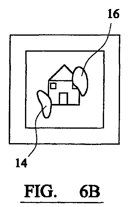
- Figure 6B shows the same image having two glare patches 14, 16 of maximum intensity
- Figure 6C illustrates the case where both glare patches 14, 16 are still present in the image but their intensity is reduced (illustrated by the shaded areas)
- Figure 6D illustrates the case where one of the glare patches 14 is present in the image (with reduced intensity) and the other glare patch has been removed altogether.
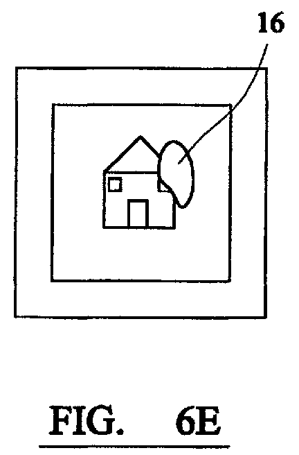
- Figure 6E illustrates a similar case where one of the glare patches 16 is present in the image (at maximum intensity) and the other glare patch has been removed.
- Figure 6F illustrates the case where one of the glare patches 14 appears in the image at maximum intensity, and the other glare patch 16 appears in the image at reduced intensity.
Abstract


Description
- This invention relates to a method and apparatus for controlling specular reflection appearing in an image captured by an image capturing device, such as a desktop or document camera or the like, and in particular for adjusting such specular reflection after an image has been captured.
- The applicants have found that in the context of a desktop or document camera, it is strongly desirable to use a strobe or the like to ensure appropriate illumination intensity and uniformity. In such close-up imaging situations, however, specularity caused by the strobe can be a serious problem in the case where the subject has a reflective or glossy surface, as in the case of many magazines, photographs and plastic objects.
- In the applicant's copending British Patent Application No. 0103828.0 entitled "Digital Cameras" filed on 16 February 2001, a number of methods are disclosed to ensure that specularity patches are eliminated from the final image. Such methods are generally based on two solutions, namely a single flash solution and a dual flash solution, both of which use at least two initial images to eliminate glare. The results of the disclosed methods is a final image which is devoid of any specular effect, i.e. as if the subject had been illuminated by uniform and diffuse light.
- However, it is not always desirable to eliminate glare from a captured image altogether, as in many cases it has aesthetic significance in the sense that it can make the captured image look more natural and ensure that it appears three-dimensional, although in many cases, the glare created in a captured image masks some of the features of the subject, which is clearly undesirable as it detrimentally affects the quality of the captured image.
- There are have been several arrangements proposed in the past in connection with digital/analog photography which are concerned with the adjustment or control of light exposure to the subject. For example, US Patent No. 4,317,620 describes a control system for controlling the intensity of the flash output of an image capturing device, depending on ambient light conditions, thereby varying the amount of glare appearing in the final image.
- Initially, the control system measures the ambient scene light and then utilises the result of that measurement to control the intensity or amount of artificial illumination provided during the exposure interval of the image capturing device. If the ambient scene light is below a first predetermined level, the control system selects maximum flash intensity; if the ambient scene light is above a second predetermined level greater than the first predetermined level, the control system selects minimum flash intensity. If the ambient scene light is determined to be between the first and second predetermined levels, then the control system progressively varies the flash intensity in a manner which is inversely proportional to the measured ambient scene light.
- However, there is no interaction between the control system and the user of the image capturing device, giving no user control of the specularity or glare appearing in the final image. Further, if the resultant glare is low, this also implies low scene brightness, which is an undesirable effect.
- US Patent No. 4,423,936 describes a photographic exposure control system and method. However, such a system could not be used to attenuate or even remove glare areas within an image because such areas are often saturated so that it is not possible to recover the original image content from the captured pixels.
- US Patent No. 4,541,704 describes a photographic camera apparatus having electronic image enhancement means intended to provide high quality, high resolution photographic prints that have been simultaneously electronically enhanced to compensate either for difficult or unfavourable scene lighting conditions as well as limitations in the film characteristics. The technique used to achieve these aims is often called dual exposure, and involves combining two (or more) images of a subject captured at different (typically increasing) exposure levels. Once again, however, there is no interaction between the user of the image capturing device and the electronic image enhancement means, all so-called enhancement of the final captured image is done automatically without any allowance for user requirements.
- US Patent No. 4,384,336 describes an arrangement which uses algorithmic techniques to selectively enhance segmented areas of a captured image, by comparing the intensities of light being reflected from the subject(s) across the whole field of view of an image capturing device. However, it is not possible to modify glare patches in an image using this type of arrangement, because only a single image is used in the modification method. A single image is insufficient for use in modifying glare patches because such patches are often saturated and, therefore, contain no useful information about the subject. Further, there is little interaction between the user and the system to allow for individual requirements.
- There are a few prior art documents which describe dual-flash camera arrangements, such as US Patent No. 5,345,284 which describes a camera arrangement including an electronic flash unit with two integrated flash heads. However, there is no disclosure or suggestion of the selective or interactive reduction, attenuation or elimination of shadows and/or glare.
- International Patent Application No. WO95/3258 describes a system, such as a digitally imaged still photography system which captures a plurality of images simultaneously under different lighting conditions or with different backgrounds, and allows such images to be subsequently blended to exhibit certain characteristics. Similarly, there is a substantial body of prior art which is concerned with the optimisation of a final image using multiple images captured using different settings, including different optical or electrical exposure (e.g. WO00/38417), different magnification and focus settings, different lighting conditions, different spectral properties of the optics, for example colour filters, or a combination of two or more of these.
- However, none of the above-mentioned known arrangements are concerned with the attenuation and/or elimination of specularity within a captured image, particularly without detrimentally affecting scene brightness of the final image.
- Perhaps the best known method of eliminating specular reflection has been used in the field of photography for many years and uses a single polarizing filter placed in front of the camera lens. By selecting an appropriate angle of rotation of such a filter, it is possible to selectively attenuate/reduce specularity/reflections from the final captured image. A well known variation, often used in machine vision, uses a polarizer to polarize the illumination source and an analyser to filter the captured diffused light only, thereby eliminating the specular component. By rotating the analyser, different amounts of specularity can be selected.
- In accordance with the present invention, there is provided apparatus for processing an image captured by an image capturing device, the apparatus comprising means for combining or blending at least one first image including a predetermined maximum level or intensity of specular reflection with a second image, which comprises said first image substantially without said specular reflection, to produce a third image, and means for adjusting the level or intensity of specular reflection in said third image to a level between said predetermined maximum level and substantially zero (inclusive).
- Also in accordance with the present invention, there is provided a method of processing an image captured by an image capturing device, the method comprising the steps of combining or blending at least one first image including a predetermined maximum level or intensity of specular reflection with a second image, which comprises said first image substantially without said specular reflection, to produce a third image, and adjusting the specular reflection appearing in said third image to a level or intensity between said predetermined maximum level and substantially zero (inclusive).
- In a preferred embodiment of the present invention, the apparatus and method involve the use of at least two first images of a subject, which could be captured using a single flash in two different positions, or two flashes, so that the resultant images each contain at least one patch of specular reflection in a different position relative to the subject. These images are used to produce the second image having no specular reflection or glare patches.
- Thus, the present invention provides a method and apparatus whereby a user can select the level of specular reflection appearing in the final image, without any detrimental effect to the scene brightness, so as to provide maximum flexibility while maintaining optimum image quality.
- The first and second images preferably have similar or substantially the same levels of exposure in the areas where little or no specular reflection appears in the first image, although this is not essential. The present invention provides a method and apparatus whereby a user can select the level or intensity of specular reflection appearing in the final image, without the need to recapture that image using a different level of exposure.
- The level of specular reflection appearing in the third image (which is a combination of the first and second images) is somewhat lower than that appearing in the first image (which includes the natural specular reflections occurring in a predetermined level of exposure) to the extent that the image content underlying the levels of high specular reflection in the first image may be clearly visible. In any event, the apparatus preferably comprises a dial or similar analog means for adjusting the level of specular reflection in the third image according to personal preference.
- In a preferred embodiment of the present invention, the apparatus includes means for allowing the user to select one or more discrete areas of the third image for adjustment.
- Thus, the apparatus may include means for selecting one or more of the areas of specular reflection in the third image, and means for allowing the user to adjust, preferably selectively, or substantially eliminate the specular reflection appearing in those areas. In one exemplary embodiment of the invention, the third image is displayed on a computer screen, or the like, the apparatus including means to allow the user to click on, or otherwise select, an area of specular reflection, and means, such as an algorithmic automatic region segmentation means, for determining and selecting the entire 'glare patch'. The user can then select the amount by which the specular reflection defining that patch is to be attenuated. Thus, in this preferred embodiment, the apparatus beneficially includes means whereby the level of specular reflection appearing in each glare patch of an image can be set to a different level, as required. In fact, as each specular area or glare patch is selected by the user, an enquiry display or user input (UI) request may automatically appear to enable the user to enter the level of attenuation required for that particular specular area or glare patch.
- Preferably, the combination of the first and second images is weighted, beneficially with a two-dimensional array of weights, in such a way as to alter the shape of a specular area or patch. For example, in one exemplary embodiment of the present invention, a Gaussian weight matrix may be applied to reduce the size of a specular area or patch, not just its intensity.
- In one exemplary embodiment of the present invention, the second image may be obtained by suitably combining two or more images captured with two or more strobes in different positions relative to the subject, as described British Patent Application No. 0103828.0 referred to above, the entire contents of which are incorporated herein by reference. In this case, the specular areas or patches which can be selected for adjustment comprise a union set of those caused by the first strobe or flash and those caused by the second strobe or flash.
- Alternatively, the second image may be obtained by suitably combining two or more images, at least one of which is captured with a strobe and at least one of which is captured with ambient illumination (i.e. without a strobe), as described in the applicant's above-mentioned co-pending application.
- An embodiment of the present invention will now be described by way of example only and with reference to the accompanying drawings, in which:
- Figure 1 is a schematic diagram illustrating an image created by combining two images captured using two different strobes or flashes;
- Figures 2A and 2B are respective graphical representations of the intensity of specular reflection appearing in the two images used to create the image of Figure 1;
- Figure 3 is a graphical representation of the image of Figure 1 having no specular reflection;
- Figure 4 is a schematic diagram to illustrate a region growing method for use in an exemplary embodiment of the present invention;
- Figure 5 is a graphical representation of the intensity of specular reflection appearing in the image of Figure 1 when the intensity of the glare patches has been selectively reduced using an exemplary embodiment of the present invention; and
- Figure 6A - 6F are schematic representations of various images which can be created using apparatus according to an exemplary embodiment of the present invention.
-
- As described in the applicant's co-pending British Patent Application No. 0103828.0, one way of obtaining an image of a subject with substantially no glare patches or specular reflection is to combine two or more images with two or more strobes or flashes in different positions relative to the subject. The resultant images might each contain one or more glare patches and, the conditions are set so that the glare patch(es) 14 appearing on one of the images will not overlap with the position(s) of the glare patch(es) 16 appearing in the other image(s), as shown schematically in Figure 1 of the drawings.
- Referring to Figures 2A and 2B of the drawings, the intensity of specularity in the first and second images respectively can be represented graphically, as shown, with the visible sections of the captured image being represented by a relatively constant waveform, and the glare patches in each image beings represented by the
peaks peaks - The image containing full specular reflection (created as a combination of the first and second images referred to above) and the image containing no specular reflection are stored in the arrangement described above, so no further images need to be captured to perform the present invention.
- In this exemplary embodiment of the present invention, the two above-mentioned images are blended. Many different methods of blending are known in the computer graphics field, and any of these methods can be used in the present invention. It should be noted, however, that in order to ensure better image quality, care needs to be taken to make sure that areas of the image with slight differences in hue/luminance are not blended as they do not correspond to specular patches.
- The individual selection of glare patches is also relatively straightforward to implement by a person skilled in the image processing art, and many suitable methods are envisaged. In fact, glare patches tend to be highly-saturated, a-chromatic and connected regions of the image, and standard region growing methods based on pixel similarity could be used to grow the specular area selected by the user. Referring to Figure 4 of the drawings, if the user selects the
glare patch 12 at the position numbered 26, region growing apparatus compares the pixels immediately adjacent the selectedpixel 26 and includes in the selected region any of the pixels which are the same or similar to the selectedpixel 26. The pixels immediately adjacent the selected region are then compared, and the region grown according to the result of the comparison. The apparatus will continue to grow the selected region in this manner until the difference between neighbouring pixels exceeds a predetermined value. Alternatively, the apparatus could be arranged to automatically find all the glare patches in the image before presenting the user with an interactive interface. - Referring to Figure 5 of the drawings, the method of the present invention can be achieved by selectively weighted blending of a first image containing maximum specular reflection or
glare patches first glare patch 10 and reduce its intensity to the level represented by the shaded area by weighting the blending of the corresponding areas of the two images. The user could then select thesecond glare patch 12 and reduce its level of intensity to the area represented by the shaded area by adjusting the weighting of the blending process accordingly. - Referring to Figures 6A - 6F of the drawings, a number of different versions of the same image are shown to more clearly illustrate the various options available to the user with the method of the present invention. Figure 6A shows an image having no specular reflection, whereas Figure 6B shows the same image having two
glare patches glare patches glare patches 14 is present in the image (with reduced intensity) and the other glare patch has been removed altogether. Figure 6E illustrates a similar case where one of theglare patches 16 is present in the image (at maximum intensity) and the other glare patch has been removed. Finally, Figure 6F illustrates the case where one of theglare patches 14 appears in the image at maximum intensity, and theother glare patch 16 appears in the image at reduced intensity. - Although the present invention has been described by way of examples of a preferred embodiment, it will be evident that other adaptations and modifications may be employed without departing from the scope of the invention as defined by the appended claims. Further, the terms and expressions employed herein have been used as terms of description and not of limitation; and, thus, there is no intent to exclude equivalents, but on the contrary it is intended to cover any and all equivalents which may be employed without departing from the scope of the invention as defined by the appended claims.
Claims (17)
- Apparatus for processing an image captured by an image capturing device, the apparatus comprising means for combining or blending at least one first image including a predetermined maximum level or intensity of specular reflection (14,16) with a second image, which comprises said first image substantially without said specular reflection (14,16), to produce a third image, and means for adjusting the level or intensity of specular reflection (14,16) appearing in said third image to a level between said predetermined maximum level and substantially zero (inclusive).
- Apparatus according to claim 1, comprising means for combining or blending at least two first images of a subject, to produce the second image having no specular reflection or glare patches (14,16).
- Apparatus according to claim 1 or claim 2, comprising analog adjustment means, such as a dial or the like, for adjusting the level or intensity of specular reflection (14,16) appearing in said third image.
- Apparatus according to any one of claims 1 to 3, including means for selecting one or more discrete areas of said third image for adjustment.
- Apparatus according to claim 4, comprising means for selecting one or more areas (14,16) of the third image containing specular reflection and means for selectively adjusting the level or intensity, or substantially eliminating, the specular reflection in the or each area (14,16).
- Apparatus according to claim 5, comprising means for allowing the user to select a portion of an area of the third image containing specular reflection (14,16), and means for automatically determining a substantially complete area of specular reflection for adjustment.
- Apparatus according to claim 6, wherein said means for automatically determining a substantially complete area of specular reflection (14,16) comprises algorithmic automatic region segmentation means.
- Apparatus according to any one of claims 5 to 7, comprising means for entering the level of attenuation of specular reflection required for each selected area.
- Apparatus according to any one of the preceding claims, wherein the combination of said first and second images is weighted, preferably with a two-dimensional array of weights, in such a way as to alter the shape of a specular area (14,16).
- Apparatus according to any one of the preceding claims, wherein said second image is obtained by combining two or more images captured with two or more strobes in different positions relative to a subject.
- Apparatus according to any one of claims 1 to 9, wherein said second image is obtained by combining two or more images, at least one of which is captured with a strobe and at least one of which is captured with ambient illumination.
- A method of processing an image captured by an image capturing device, the method comprising the steps of combining or blending at least one first image including a predetermined maximum level or intensity of specular reflection with a second image, which comprises said first image substantially without said specular reflection, to produce a third image, and adjusting the specular reflection appearing in said third image to a level or intensity between said predetermined maximum level and substantially zero (inclusive).
- A method according to claim 12, comprising the step of combining or blending at least two first images of a subject to produce the second image having no specular reflection or glare patches.
- A method according to claim 12, or claim 13, including the step of selecting one or more discrete areas of said third image for adjustment.
- A method according to claim 14, comprising the steps of selecting one or more areas of said third image containing specular reflection, and selectively adjusting the level or intensity of specular reflection and/or eliminating said specular reflection in the or each selected area.
- A method according to any one of claims 12 to 15, comprising the step of obtaining said second image by combining two or more images captured with two or more strobes in different positions relative to a subject.
- A method according to any one of claims 12 to 15, comprising the step of obtaining said second image by combining two or more images, at least one of which is captured with a strobe and at least one of which is captured with ambient illumination.
Applications Claiming Priority (2)
| Application Number | Priority Date | Filing Date | Title |
|---|---|---|---|
| GB0112047 | 2001-05-17 | ||
| GB0112047A GB2375676A (en) | 2001-05-17 | 2001-05-17 | Reducing the effects of specular reflections appearing in an image |
Publications (2)
| Publication Number | Publication Date |
|---|---|
| EP1259062A2 true EP1259062A2 (en) | 2002-11-20 |
| EP1259062A3 EP1259062A3 (en) | 2004-09-29 |
Family
ID=9914803
Family Applications (1)
| Application Number | Title | Priority Date | Filing Date |
|---|---|---|---|
| EP02253156A Withdrawn EP1259062A3 (en) | 2001-05-17 | 2002-05-03 | Specular reflection in captured images |
Country Status (3)
| Country | Link |
|---|---|
| US (1) | US7136537B2 (en) |
| EP (1) | EP1259062A3 (en) |
| GB (1) | GB2375676A (en) |
Cited By (3)
| Publication number | Priority date | Publication date | Assignee | Title |
|---|---|---|---|---|
| EP1856651A2 (en) * | 2005-01-26 | 2007-11-21 | PSC Scanning, Inc. | Data reader and methods for imaging targets subject to specular reflection |
| DE102014017062B3 (en) * | 2014-11-14 | 2015-12-03 | Technische Universität Ilmenau | Method for compensation of reflections during image acquisition |
| EP3696722A1 (en) * | 2019-02-14 | 2020-08-19 | Continental Automotive GmbH | Method of removing stray light from a vehicle window in a camera arrangement, camera arrangement for using said method and computer programs |
Families Citing this family (26)
| Publication number | Priority date | Publication date | Assignee | Title |
|---|---|---|---|---|
| GB2372391A (en) * | 2001-02-16 | 2002-08-21 | Hewlett Packard Co | Removal of specular reflection |
| DE102004016564A1 (en) * | 2004-03-30 | 2006-02-16 | Frie, Werner Rudolf, Dr. | Flashlight reflection compensation system for camera with one flashlight involves taking two photographs with different intensities of flash and identifying and erasing bright reflections from flash |
| US8249309B2 (en) * | 2004-04-02 | 2012-08-21 | K-Nfb Reading Technology, Inc. | Image evaluation for reading mode in a reading machine |
| US20050276508A1 (en) * | 2004-06-15 | 2005-12-15 | Lockheed Martin Corporation | Methods and systems for reducing optical noise |
| US7593593B2 (en) | 2004-06-16 | 2009-09-22 | Microsoft Corporation | Method and system for reducing effects of undesired signals in an infrared imaging system |
| US7760962B2 (en) * | 2005-03-30 | 2010-07-20 | Casio Computer Co., Ltd. | Image capture apparatus which synthesizes a plurality of images obtained by shooting a subject from different directions, to produce an image in which the influence of glare from a light is reduced |
| US7911444B2 (en) | 2005-08-31 | 2011-03-22 | Microsoft Corporation | Input method for surface of interactive display |
| JP5073996B2 (en) * | 2006-09-20 | 2012-11-14 | オリンパス株式会社 | Image processing device |
| US8212857B2 (en) | 2007-01-26 | 2012-07-03 | Microsoft Corporation | Alternating light sources to reduce specular reflection |
| JP4924114B2 (en) * | 2007-03-09 | 2012-04-25 | 株式会社ニコン | Image processing program and image processing method |
| US7995854B2 (en) * | 2008-03-28 | 2011-08-09 | Tandent Vision Science, Inc. | System and method for identifying complex tokens in an image |
| US8730356B2 (en) * | 2011-03-07 | 2014-05-20 | Sony Corporation | System and method for automatic flash removal from images |
| WO2013002810A1 (en) * | 2011-06-30 | 2013-01-03 | Hewlett-Packard Development Company, L.P. | Filter with first polarized portion and a second polarized portion |
| US8743426B2 (en) | 2012-06-27 | 2014-06-03 | 3M Innovative Properties Company | Image enhancement methods |
| US8610976B1 (en) | 2012-06-27 | 2013-12-17 | 3M Innovative Properties Company | Image enhancement methods |
| US20140002722A1 (en) * | 2012-06-27 | 2014-01-02 | 3M Innovative Properties Company | Image enhancement methods |
| EP2912602A4 (en) | 2012-10-23 | 2016-03-16 | Ishay Sivan | Real time assessment of picture quality |
| DE102013106556A1 (en) * | 2013-06-24 | 2014-12-24 | Qioptiq Photonics Gmbh & Co. Kg | Method of operating a dental camera |
| CN104376545B (en) * | 2013-08-16 | 2018-12-14 | 联想(北京)有限公司 | A kind of method and a kind of electronic equipment of information processing |
| US9275448B2 (en) * | 2013-08-27 | 2016-03-01 | Xerox Corporation | Flash/no-flash imaging for binarization |
| US9237274B2 (en) * | 2013-11-14 | 2016-01-12 | Empire Technology Development Llc | Reduction of glare in augmented reality |
| JP5787964B2 (en) * | 2013-11-15 | 2015-09-30 | 株式会社Pfu | Imaging system and image data generation method |
| JP5841587B2 (en) * | 2013-12-25 | 2016-01-13 | 株式会社Pfu | Imaging system |
| US9769392B1 (en) * | 2014-06-27 | 2017-09-19 | Amazon Technologies, Inc. | Imaging system for addressing specular reflection |
| KR102614906B1 (en) * | 2016-12-05 | 2023-12-18 | 삼성전자주식회사 | Method and apparatus of image processing |
| US10142568B2 (en) * | 2017-02-13 | 2018-11-27 | Semiconductor Components Industries, Llc | Methods and apparatus for vignette and out-of-focus correction |
Citations (3)
| Publication number | Priority date | Publication date | Assignee | Title |
|---|---|---|---|---|
| US5550641A (en) * | 1991-05-15 | 1996-08-27 | Gentech Corporation | System and method for rendering images |
| WO1999038121A1 (en) * | 1998-01-27 | 1999-07-29 | Sensar, Inc. | Method and apparatus for removal of bright or dark spots by the fusion of multiple images |
| GB2372391A (en) | 2001-02-16 | 2002-08-21 | Hewlett Packard Co | Removal of specular reflection |
Family Cites Families (34)
| Publication number | Priority date | Publication date | Assignee | Title |
|---|---|---|---|---|
| GB1038280A (en) | 1965-06-24 | 1966-08-10 | James Edman Cox | Book support |
| US4317620A (en) | 1980-01-17 | 1982-03-02 | Polaroid Corporation | Variable proportional fill flash |
| US4384336A (en) | 1980-08-29 | 1983-05-17 | Polaroid Corporation | Method and apparatus for lightness imaging |
| US4423936A (en) | 1982-07-26 | 1984-01-03 | Polaroid Corporation | Photographic exposure control system and method |
| US4541704A (en) | 1984-09-10 | 1985-09-17 | Polaroid Corporation | Photographic camera with electronic image enhancement |
| US4605970A (en) | 1984-10-01 | 1986-08-12 | Tektronix, Inc. | Method and apparatus for calibrating an optical document digitizer |
| US4724330A (en) | 1986-09-24 | 1988-02-09 | Xerox Corporation | Self aligning raster input scanner |
| US5194729A (en) * | 1989-09-29 | 1993-03-16 | Minolta Camera Co., Ltd. | Document reading apparatus with area recognizing sensor and obstacle detection |
| JP3063099B2 (en) * | 1989-09-29 | 2000-07-12 | ミノルタ株式会社 | Document reading device |
| JPH0514271Y2 (en) | 1990-02-16 | 1993-04-16 | ||
| US5091654A (en) | 1990-08-28 | 1992-02-25 | Xerox Corporation | Method of automatically setting document registration and locating calibration strip |
| JP3082289B2 (en) * | 1991-05-14 | 2000-08-28 | 富士ゼロックス株式会社 | Image processing device |
| US5585926A (en) * | 1991-12-05 | 1996-12-17 | Minolta Co., Ltd. | Document reading apparatus capable of rectifying a picked up image data of documents |
| JP3074967B2 (en) * | 1992-10-27 | 2000-08-07 | 松下電器産業株式会社 | High dynamic range imaging / synthesis method and high dynamic range imaging apparatus |
| DE69430967T2 (en) | 1993-04-30 | 2002-11-07 | Xerox Corp | Interactive copying system |
| US5517242A (en) * | 1993-06-29 | 1996-05-14 | Kabushiki Kaisha Toyota Chuo Kenkyusho | Image sensing device having expanded dynamic range |
| WO1995032581A1 (en) | 1994-05-23 | 1995-11-30 | Out-Takes, Inc. | Seamless composite photography system |
| DE4445386C1 (en) | 1994-12-20 | 1996-05-02 | Ibm | Separation of foreground and background information on document |
| JP3072236B2 (en) * | 1994-12-26 | 2000-07-31 | シャープ株式会社 | Image input device |
| US6057851A (en) * | 1995-10-06 | 2000-05-02 | International Business Machines Corp. | Computer graphics system having efficient texture mapping with perspective correction |
| KR20000015837A (en) * | 1996-05-23 | 2000-03-15 | 알카텔 유에스에이 소싱 엘.피. | System and method for supporting and managing telecommunications services |
| US5764383A (en) * | 1996-05-30 | 1998-06-09 | Xerox Corporation | Platenless book scanner with line buffering to compensate for image skew |
| GB9614837D0 (en) | 1996-07-12 | 1996-09-04 | Rank Xerox Ltd | Interactive desktop system with multiple image capture and display modes |
| JPH10155055A (en) * | 1996-11-21 | 1998-06-09 | Fujitsu Ltd | Paper carrier controller for optical image reader |
| US6088612A (en) * | 1997-04-04 | 2000-07-11 | Medtech Research Corporation | Method and apparatus for reflective glare removal in digital photography useful in cervical cancer detection |
| US5990901A (en) * | 1997-06-27 | 1999-11-23 | Microsoft Corporation | Model based image editing and correction |
| EP0912047B1 (en) * | 1997-10-23 | 2004-04-07 | Olympus Optical Co., Ltd. | Imaging apparatus comprising means for expanding the dynamic range |
| US5987270A (en) | 1997-12-17 | 1999-11-16 | Hewlett-Packard Company | Digital copying machine that automasks data for small originals if a document feeder is present |
| US6393160B1 (en) * | 1998-03-13 | 2002-05-21 | Applied Science Fiction | Image defect correction in transform space |
| TW468331B (en) * | 1998-09-30 | 2001-12-11 | Hitachi Ltd | Non-contact image reading device and the system using the same |
| WO2000038417A1 (en) | 1998-12-22 | 2000-06-29 | Koninklijke Philips Electronics N.V. | Method of and device for forming an image of an object from a plurality of images |
| US6297889B1 (en) * | 1998-12-22 | 2001-10-02 | Xerox Corporation | Logic-based image processing method |
| US6512539B1 (en) * | 1999-09-29 | 2003-01-28 | Xerox Corporation | Document periscope |
| US6454410B1 (en) * | 1999-10-20 | 2002-09-24 | The Trustees Of The University Of Pennsylvania | Mosaicing and enhancement of images for ophthalmic diagnosis and documentation |
-
2001
- 2001-05-17 GB GB0112047A patent/GB2375676A/en not_active Withdrawn
-
2002
- 2002-05-03 EP EP02253156A patent/EP1259062A3/en not_active Withdrawn
- 2002-05-15 US US10/144,999 patent/US7136537B2/en not_active Expired - Fee Related
Patent Citations (3)
| Publication number | Priority date | Publication date | Assignee | Title |
|---|---|---|---|---|
| US5550641A (en) * | 1991-05-15 | 1996-08-27 | Gentech Corporation | System and method for rendering images |
| WO1999038121A1 (en) * | 1998-01-27 | 1999-07-29 | Sensar, Inc. | Method and apparatus for removal of bright or dark spots by the fusion of multiple images |
| GB2372391A (en) | 2001-02-16 | 2002-08-21 | Hewlett Packard Co | Removal of specular reflection |
Non-Patent Citations (1)
| Title |
|---|
| JEREMY BIRN: "DIGITAL LIGHTINING & RENDERING, CHAPTER 10 - COMPOSITING", July 2000, NEW RIDERS PUBLISHING, USA, XP002449332 * |
Cited By (4)
| Publication number | Priority date | Publication date | Assignee | Title |
|---|---|---|---|---|
| EP1856651A2 (en) * | 2005-01-26 | 2007-11-21 | PSC Scanning, Inc. | Data reader and methods for imaging targets subject to specular reflection |
| EP1856651A4 (en) * | 2005-01-26 | 2010-08-04 | Datalogic Scanning Inc | Data reader and methods for imaging targets subject to specular reflection |
| DE102014017062B3 (en) * | 2014-11-14 | 2015-12-03 | Technische Universität Ilmenau | Method for compensation of reflections during image acquisition |
| EP3696722A1 (en) * | 2019-02-14 | 2020-08-19 | Continental Automotive GmbH | Method of removing stray light from a vehicle window in a camera arrangement, camera arrangement for using said method and computer programs |
Also Published As
| Publication number | Publication date |
|---|---|
| EP1259062A3 (en) | 2004-09-29 |
| US7136537B2 (en) | 2006-11-14 |
| US20020172432A1 (en) | 2002-11-21 |
| GB2375676A (en) | 2002-11-20 |
| GB0112047D0 (en) | 2001-07-11 |
Similar Documents
| Publication | Publication Date | Title |
|---|---|---|
| US7136537B2 (en) | Specular reflection in captured images | |
| JP4880292B2 (en) | Image processing method, image processing program, and image processing apparatus | |
| US8644638B2 (en) | Automatic localized adjustment of image shadows and highlights | |
| US7027662B2 (en) | Method and apparatus for the removal of flash artifacts | |
| JP3796174B2 (en) | Imaging system, image processing apparatus, and camera | |
| US7916941B2 (en) | Methods and apparatuses for restoring color and enhancing electronic images | |
| CN106210437B (en) | Image processing apparatus and projecting apparatus | |
| CN107948538A (en) | Imaging method, device, mobile terminal and storage medium | |
| WO1999039307A1 (en) | System for simulating the depth of field of an image in two-dimensional space and method of operation | |
| US6859618B1 (en) | Exposure compensation method and system employing meter matrix and flash | |
| JP2003284060A (en) | Vehicle having display unit for automobile, noctvision recognizing unit for automobile and infrared noctvision recognizing unit for automobile | |
| Bimber et al. | Closed-loop feedback illumination for optical inverse tone-mapping in light microscopy | |
| US20060033825A1 (en) | Method for enhancing images of non-uniform brightness | |
| McCann | Art, science, and appearance in HDR | |
| US6529243B1 (en) | Method for electronic reduction of the contrast of video images as early as during recording | |
| US6458492B1 (en) | Mask changing the brightness profile of a photographic copy | |
| US20210166399A1 (en) | Background Balancing in a Collection of Digital Images | |
| WO1998027744A1 (en) | Imaging system | |
| EP1976273B1 (en) | Image processing apparatus, imaging apparatus and image processing program | |
| JPH1093859A (en) | Image processing unit and image processing method | |
| US20040109077A1 (en) | Camera, imaging system and illuminations sensor | |
| WO2020084894A1 (en) | Multi-camera system, control value calculation method and control device | |
| Friederichsen | Recent Advances in Smartphone Computational Photography | |
| CN108965707B (en) | Automatic bottom-removing shooting system | |
| JPH10112799A (en) | Flair correction method |
Legal Events
| Date | Code | Title | Description |
|---|---|---|---|
| PUAI | Public reference made under article 153(3) epc to a published international application that has entered the european phase |
Free format text: ORIGINAL CODE: 0009012 |
|
| AK | Designated contracting states |
Kind code of ref document: A2 Designated state(s): AT BE CH CY DE DK ES FI FR GB GR IE IT LI LU MC NL PT SE TR |
|
| AX | Request for extension of the european patent |
Free format text: AL;LT;LV;MK;RO;SI |
|
| PUAL | Search report despatched |
Free format text: ORIGINAL CODE: 0009013 |
|
| AK | Designated contracting states |
Kind code of ref document: A3 Designated state(s): AT BE CH CY DE DK ES FI FR GB GR IE IT LI LU MC NL PT SE TR |
|
| AX | Request for extension of the european patent |
Extension state: AL LT LV MK RO SI |
|
| 17P | Request for examination filed |
Effective date: 20050207 |
|
| AKX | Designation fees paid |
Designated state(s): DE FR GB |
|
| 17Q | First examination report despatched |
Effective date: 20050609 |
|
| RAP1 | Party data changed (applicant data changed or rights of an application transferred) |
Owner name: HEWLETT-PACKARD DEVELOPMENT COMPANY, L.P. |
|
| STAA | Information on the status of an ep patent application or granted ep patent |
Free format text: STATUS: THE APPLICATION IS DEEMED TO BE WITHDRAWN |
|
| 18D | Application deemed to be withdrawn |
Effective date: 20141202 |