EP1265145B1 - Log collecting/analyzing system with separated functions of collecting log information and analyzing the same - Google Patents
Log collecting/analyzing system with separated functions of collecting log information and analyzing the same Download PDFInfo
- Publication number
- EP1265145B1 EP1265145B1 EP02011865A EP02011865A EP1265145B1 EP 1265145 B1 EP1265145 B1 EP 1265145B1 EP 02011865 A EP02011865 A EP 02011865A EP 02011865 A EP02011865 A EP 02011865A EP 1265145 B1 EP1265145 B1 EP 1265145B1
- Authority
- EP
- European Patent Office
- Prior art keywords
- log
- information
- terminal device
- user
- analyzing
- Prior art date
- Legal status (The legal status is an assumption and is not a legal conclusion. Google has not performed a legal analysis and makes no representation as to the accuracy of the status listed.)
- Expired - Lifetime
Links
Images


Classifications
-
- A—HUMAN NECESSITIES
- A63—SPORTS; GAMES; AMUSEMENTS
- A63F—CARD, BOARD, OR ROULETTE GAMES; INDOOR GAMES USING SMALL MOVING PLAYING BODIES; VIDEO GAMES; GAMES NOT OTHERWISE PROVIDED FOR
- A63F13/00—Video games, i.e. games using an electronically generated display having two or more dimensions
- A63F13/70—Game security or game management aspects
- A63F13/79—Game security or game management aspects involving player-related data, e.g. identities, accounts, preferences or play histories
-
- A—HUMAN NECESSITIES
- A63—SPORTS; GAMES; AMUSEMENTS
- A63F—CARD, BOARD, OR ROULETTE GAMES; INDOOR GAMES USING SMALL MOVING PLAYING BODIES; VIDEO GAMES; GAMES NOT OTHERWISE PROVIDED FOR
- A63F13/00—Video games, i.e. games using an electronically generated display having two or more dimensions
- A63F13/30—Interconnection arrangements between game servers and game devices; Interconnection arrangements between game devices; Interconnection arrangements between game servers
- A63F13/35—Details of game servers
- A63F13/352—Details of game servers involving special game server arrangements, e.g. regional servers connected to a national server or a plurality of servers managing partitions of the game world
-
- A—HUMAN NECESSITIES
- A63—SPORTS; GAMES; AMUSEMENTS
- A63F—CARD, BOARD, OR ROULETTE GAMES; INDOOR GAMES USING SMALL MOVING PLAYING BODIES; VIDEO GAMES; GAMES NOT OTHERWISE PROVIDED FOR
- A63F13/00—Video games, i.e. games using an electronically generated display having two or more dimensions
- A63F13/70—Game security or game management aspects
- A63F13/71—Game security or game management aspects using secure communication between game devices and game servers, e.g. by encrypting game data or authenticating players
-
- A—HUMAN NECESSITIES
- A63—SPORTS; GAMES; AMUSEMENTS
- A63F—CARD, BOARD, OR ROULETTE GAMES; INDOOR GAMES USING SMALL MOVING PLAYING BODIES; VIDEO GAMES; GAMES NOT OTHERWISE PROVIDED FOR
- A63F13/00—Video games, i.e. games using an electronically generated display having two or more dimensions
- A63F13/70—Game security or game management aspects
- A63F13/77—Game security or game management aspects involving data related to game devices or game servers, e.g. configuration data, software version or amount of memory
-
- G—PHYSICS
- G06—COMPUTING; CALCULATING OR COUNTING
- G06F—ELECTRIC DIGITAL DATA PROCESSING
- G06F11/00—Error detection; Error correction; Monitoring
- G06F11/30—Monitoring
- G06F11/34—Recording or statistical evaluation of computer activity, e.g. of down time, of input/output operation ; Recording or statistical evaluation of user activity, e.g. usability assessment
- G06F11/3466—Performance evaluation by tracing or monitoring
- G06F11/3476—Data logging
-
- G—PHYSICS
- G06—COMPUTING; CALCULATING OR COUNTING
- G06F—ELECTRIC DIGITAL DATA PROCESSING
- G06F11/00—Error detection; Error correction; Monitoring
- G06F11/30—Monitoring
- G06F11/34—Recording or statistical evaluation of computer activity, e.g. of down time, of input/output operation ; Recording or statistical evaluation of user activity, e.g. usability assessment
- G06F11/3466—Performance evaluation by tracing or monitoring
- G06F11/3495—Performance evaluation by tracing or monitoring for systems
-
- A—HUMAN NECESSITIES
- A63—SPORTS; GAMES; AMUSEMENTS
- A63F—CARD, BOARD, OR ROULETTE GAMES; INDOOR GAMES USING SMALL MOVING PLAYING BODIES; VIDEO GAMES; GAMES NOT OTHERWISE PROVIDED FOR
- A63F13/00—Video games, i.e. games using an electronically generated display having two or more dimensions
- A63F13/30—Interconnection arrangements between game servers and game devices; Interconnection arrangements between game devices; Interconnection arrangements between game servers
- A63F13/33—Interconnection arrangements between game servers and game devices; Interconnection arrangements between game devices; Interconnection arrangements between game servers using wide area network [WAN] connections
- A63F13/335—Interconnection arrangements between game servers and game devices; Interconnection arrangements between game devices; Interconnection arrangements between game servers using wide area network [WAN] connections using Internet
-
- A—HUMAN NECESSITIES
- A63—SPORTS; GAMES; AMUSEMENTS
- A63F—CARD, BOARD, OR ROULETTE GAMES; INDOOR GAMES USING SMALL MOVING PLAYING BODIES; VIDEO GAMES; GAMES NOT OTHERWISE PROVIDED FOR
- A63F13/00—Video games, i.e. games using an electronically generated display having two or more dimensions
- A63F13/90—Constructional details or arrangements of video game devices not provided for in groups A63F13/20 or A63F13/25, e.g. housing, wiring, connections or cabinets
- A63F13/95—Storage media specially adapted for storing game information, e.g. video game cartridges
-
- A—HUMAN NECESSITIES
- A63—SPORTS; GAMES; AMUSEMENTS
- A63F—CARD, BOARD, OR ROULETTE GAMES; INDOOR GAMES USING SMALL MOVING PLAYING BODIES; VIDEO GAMES; GAMES NOT OTHERWISE PROVIDED FOR
- A63F2300/00—Features of games using an electronically generated display having two or more dimensions, e.g. on a television screen, showing representations related to the game
- A63F2300/20—Features of games using an electronically generated display having two or more dimensions, e.g. on a television screen, showing representations related to the game characterised by details of the game platform
- A63F2300/206—Game information storage, e.g. cartridges, CD ROM's, DVD's, smart cards
-
- A—HUMAN NECESSITIES
- A63—SPORTS; GAMES; AMUSEMENTS
- A63F—CARD, BOARD, OR ROULETTE GAMES; INDOOR GAMES USING SMALL MOVING PLAYING BODIES; VIDEO GAMES; GAMES NOT OTHERWISE PROVIDED FOR
- A63F2300/00—Features of games using an electronically generated display having two or more dimensions, e.g. on a television screen, showing representations related to the game
- A63F2300/40—Features of games using an electronically generated display having two or more dimensions, e.g. on a television screen, showing representations related to the game characterised by details of platform network
- A63F2300/407—Data transfer via internet
-
- A—HUMAN NECESSITIES
- A63—SPORTS; GAMES; AMUSEMENTS
- A63F—CARD, BOARD, OR ROULETTE GAMES; INDOOR GAMES USING SMALL MOVING PLAYING BODIES; VIDEO GAMES; GAMES NOT OTHERWISE PROVIDED FOR
- A63F2300/00—Features of games using an electronically generated display having two or more dimensions, e.g. on a television screen, showing representations related to the game
- A63F2300/50—Features of games using an electronically generated display having two or more dimensions, e.g. on a television screen, showing representations related to the game characterized by details of game servers
- A63F2300/53—Features of games using an electronically generated display having two or more dimensions, e.g. on a television screen, showing representations related to the game characterized by details of game servers details of basic data processing
- A63F2300/532—Features of games using an electronically generated display having two or more dimensions, e.g. on a television screen, showing representations related to the game characterized by details of game servers details of basic data processing using secure communication, e.g. by encryption, authentication
-
- A—HUMAN NECESSITIES
- A63—SPORTS; GAMES; AMUSEMENTS
- A63F—CARD, BOARD, OR ROULETTE GAMES; INDOOR GAMES USING SMALL MOVING PLAYING BODIES; VIDEO GAMES; GAMES NOT OTHERWISE PROVIDED FOR
- A63F2300/00—Features of games using an electronically generated display having two or more dimensions, e.g. on a television screen, showing representations related to the game
- A63F2300/50—Features of games using an electronically generated display having two or more dimensions, e.g. on a television screen, showing representations related to the game characterized by details of game servers
- A63F2300/53—Features of games using an electronically generated display having two or more dimensions, e.g. on a television screen, showing representations related to the game characterized by details of game servers details of basic data processing
- A63F2300/535—Features of games using an electronically generated display having two or more dimensions, e.g. on a television screen, showing representations related to the game characterized by details of game servers details of basic data processing for monitoring, e.g. of user parameters, terminal parameters, application parameters, network parameters
-
- A—HUMAN NECESSITIES
- A63—SPORTS; GAMES; AMUSEMENTS
- A63F—CARD, BOARD, OR ROULETTE GAMES; INDOOR GAMES USING SMALL MOVING PLAYING BODIES; VIDEO GAMES; GAMES NOT OTHERWISE PROVIDED FOR
- A63F2300/00—Features of games using an electronically generated display having two or more dimensions, e.g. on a television screen, showing representations related to the game
- A63F2300/50—Features of games using an electronically generated display having two or more dimensions, e.g. on a television screen, showing representations related to the game characterized by details of game servers
- A63F2300/55—Details of game data or player data management
- A63F2300/552—Details of game data or player data management for downloading to client devices, e.g. using OS version, hardware or software profile of the client device
-
- A—HUMAN NECESSITIES
- A63—SPORTS; GAMES; AMUSEMENTS
- A63F—CARD, BOARD, OR ROULETTE GAMES; INDOOR GAMES USING SMALL MOVING PLAYING BODIES; VIDEO GAMES; GAMES NOT OTHERWISE PROVIDED FOR
- A63F2300/00—Features of games using an electronically generated display having two or more dimensions, e.g. on a television screen, showing representations related to the game
- A63F2300/50—Features of games using an electronically generated display having two or more dimensions, e.g. on a television screen, showing representations related to the game characterized by details of game servers
- A63F2300/55—Details of game data or player data management
- A63F2300/5546—Details of game data or player data management using player registration data, e.g. identification, account, preferences, game history
-
- Y—GENERAL TAGGING OF NEW TECHNOLOGICAL DEVELOPMENTS; GENERAL TAGGING OF CROSS-SECTIONAL TECHNOLOGIES SPANNING OVER SEVERAL SECTIONS OF THE IPC; TECHNICAL SUBJECTS COVERED BY FORMER USPC CROSS-REFERENCE ART COLLECTIONS [XRACs] AND DIGESTS
- Y10—TECHNICAL SUBJECTS COVERED BY FORMER USPC
- Y10S—TECHNICAL SUBJECTS COVERED BY FORMER USPC CROSS-REFERENCE ART COLLECTIONS [XRACs] AND DIGESTS
- Y10S707/00—Data processing: database and file management or data structures
- Y10S707/99941—Database schema or data structure
- Y10S707/99944—Object-oriented database structure
- Y10S707/99945—Object-oriented database structure processing
Definitions
- the present invention relates to a log collecting/analyzing system, a method of log collection, a log collection program, a method of log analysis, a log analysis program, a log collecting device, a log analyzing device, a log collection terminal device and a log server, which comprises separated functions of collecting log information and analyzing collected log information, and in which the log information is collected at client side and transmitted to server side, and the server side stores the log information to analyze.
- log collecting/analyzing system is used for the purpose of observing something, in a system for providing certain service. For instance, if the log collecting/analyzing system is applied to some on-line system, it is possible to ascertain how unfair access, fault of system or so forth occurred by analyzing log. In addition, if the log collecting/analyzing system is applied to WWW (World Wide Web) server, it is possible to record details that what-like client referred to, when, and what-like contents by analyzing log. And, as a result, it becomes possible to learn interest level of the user on the contents for example.
- WWW World Wide Web
- document EP-A-0 913 774 discloses a managing computer for a plurality of computers connected via a network that acquires log information and event information from any of said plurality of computers and stores operation definition information used to define a schedule of process operations executed in the plurality of computers in relation to the log information and the event information into a database.
- the present embodiment provides entirely new example of log collecting/analyzing system in which client side collects log information and transmits the collected log information to server side, and the server side stores therein the transmitted log information to analyze.
- the present invention separates function of log collecting/analyzing system into two functions of collecting log and storing/analyzing the collected log in which the client side collects logs while the server side stores and analyzes the logs.
- function of the client side is to establish basic structure of log and then generating desired log information from the basic structure of log.
- function of the log server is to execute storage-analysis of the received log information and then analyzing the log information in every application program.
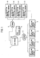
- FIG.1 illustrates the whole configuration of the log collecting/analyzing system.
- Log collection terminal device devices 1 to 4 of being client terminal device devices to which client side software and client side hardware for collecting log are provided are connected to network 5 respectively. It should be noted that the log collection terminal device is capable of being added to increase without limiting the number of piece by sharing the network 5 .
- the log collection terminal device devices 1 to 4 collect logs and then store therein logs temporarily.
- the log collection terminal device devices 1 to 4 transmit log information that is collected and stored therein temporarily by the log collection terminal device devices 1 to 4 toward log server 7 via the network 5 .
- the log server 7 is provided with log storage area 6 for storing therein received log information. Then, the log server 7 stores the log information transmitted from the log collection terminal device devices 1 to 4 in the log storage area 6 .
- the log server 7 takes out the log information stored in the log storage area 6 and then executes analysis processing of the log information, before storing the analyzed result in the log storage area 6 again.
- log collection service utilizing companies 9 to 12 .
- design and mounting are established so that collection program when conducting log collection and analysis processing correspond to log collection side and log analysis side respectively.
- the log collection service utilizing companies 9 to 12 input acquisition requirement of the analyzed result to the log server 7 via the network 8 .
- the log server 7 which has received the acquisition requirement from the log collection service utilizing companies 9 to 12 authenticates the log collection service utilizing companies 9 to 12 connected to the network and then the log server 7 adopts or rejects companies 9 to 12 on the basis of authentication result, after that, the log server 7 transmits log analyzed result to the authenticated companies.
- a plurality of log collection service utilizing companies are connectable to the log server 7 via the network 8 . Then, the log server 7 is capable of transmitting log analyzed result toward any of the log collection service utilizing companies 9 to 12 that are authenticated to be connected to the log server 7 via the network 8.
- FIG.2 illustrates internal configuration of one log collection terminal device.
- the log collection terminal device comprises an image/sound control unit 13 , CPU (central calculation processing unit) 14 , a communication control unit 15 , media control unit 16 , RAM 17 , external memory control unit 18 , input control unit 19 , HDD (magnetic recording medium) 20 , as principal configuration elements, in which these respective elements are connected with each other via bus.
- CPU central calculation processing unit
- HDD magnetic recording medium
- the image/sound control unit 13 controls image output for monitor unit that is not illustrated and voice output for speaker and so forth or input from video camera and microphone.
- the CPU 14 controls total operation of the log collection terminal device.
- the communication control unit 15 that is connected to the network 5 illustrated in FIG.1 controls communication of being executed between the communication control unit 15 and the network 5 .
- the media control unit 16 controls media drive which is not illustrated, in that the media control unit 16 inputs therein signals from external recording media such as CD-ROM and/or DVD-ROM and so forth equipped with the media drive or the media control unit 16 causes the external recording media to write signals.
- the HDD 20 records various kinds of programs containing program for realizing log collection processing of the present embodiment and/or various kind of data.
- the RAM 17 stores therein program read out from the HDD 20 and/or data utilized on the occasion of execution of various kinds of processing.
- the external memory control unit 18 which is connected to nonvolatile memory 21 existing at external part of the log collection terminal device and then the external memory unit 18 controls transmission/reception of the data as well as write/read of the data between the external memory control unit and the memory 21 .
- the input control unit 19 controls input units to be user interface such as keyboard, mouse, and so forth that are not illustrated.
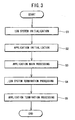
- processing illustrated in FIG.3 is one that is mainly achieved by function of the CPU mounted on the log collection terminal device.
- the log collection terminal device provides initialization of log collecting/analyzing system illustrated FIG.1 in order to permit utilization of the log collecting/analyzing system.
- the log collection terminal device judges whether the log collection terminal device is capable of using the log collecting/analyzing system illustrated in FIG.1 , and so forth.
- initialization of application is executed as processing of STEP S2 .
- the log collection terminal device When completing the initialization of the application, the log collection terminal device provides main processing (application main processing) of the application as processing of STEP S3 . It should be noted that the application main processing will be described later. Then, the log collection terminal device, when completing the application main processing, executes processing in order to terminate utilization of the log collecting/analyzing system illustrated in FIG.1 as processing of STEP S4 . According to this termination processing, the log collection terminal device stores log information maintained in the RAM 17 for the sake of the log collecting/analyzing system into the HDD 20 and so forth, further the log collection terminal device conducts release of resources that are used for the log collecting/analyzing system. After that, the log collection terminal device conducts termination processing of the application of the present embodiment as processing of STEP S5 . After that, the log collection terminal devices 1 to 4 become condition in which the log collection terminal device devices 1 to 4 are capable of being terminated.
- FIG.4 illustrates a flowchart for initialization processing of the log collection terminal device for the sake of utilization of the log collecting/analyzing system.
- the log collection terminal device conducts login processing of the log user as processing of STEP S6. This login processing is necessary processing for identifying the user who uses the log collecting/analyzing system, and the processing informs the information concerning the user thus the user is grasped.
- log user registration processing is conducted in processing of STEP S7 .
- the log collection analysis terminal device ascertains whether double registration is conducted in this registration, or whether the user is unfair user, in such a way as to compare information registered beforehand with information input by the log user registration, and so forth.
- processing of STEP S8 when succeeding user registration, the log collection terminal device continues log system initialization.
- user registration is not made by factor of some kind, the log collection terminal device interrupts log system initialization and then the log collection terminal device executes log system no use condition setting at processing of STEP S12 , thereafter, the log collection terminal device concludes the log system initialization.
- the log collection terminal device when registration ascertainment as log user is succeeded, the log collection terminal device inputs therein log user information stored in, for instance, the HDD 20 and/or the nonvolatile memory 21 as processing of STEP S9, further, the log collection terminal device inputs therein log system utilization title information as processing of STEP S10.
- the log collection terminal device ascertains whether the log system can be utilized as processing of STEP S11. It should be noted that this ascertainment is conducted to control period of using the log system. For instance, in cases where certain log service is established so as to provide service only one month, if, for instance, service period of the log collecting/analyzing system is concluded, it becomes not possible to transmit log to the log server 7 , therefore, the log collection terminal device ascertains whether the log collecting/analyzing system is capable of being used in order to forestall occurrence of such condition.
- operation of the log collection terminal device proceeds to processing of STEP S12, and then setting the log system into use prohibition condition.
- This use prohibition condition is that the log collection terminal device overrides records of log in the log collecting/analyzing system, and function of transmission of log for the log server 7 , and so forth.
- an application that employs the log collecting/analyzing system is capable of executing processing in the same way as that of normal function regardless of whether the log collecting/analyzing system is effective or ineffective, however, specific processing of recording of logs and/or transmitting of logs are not executed.
- the log collection terminal device realizes control of the use prohibition condition in such a way as to internally control whether processing of recording log and transmitting log is reflected.
- the log collection terminal device executes transmission processing of logs that are not transmitted yet as processing of STEP S13.
- the present invention is characterized in that it is possible to realize function of collecting log in off-line environment.
- Processing of STEP S13 relates to the function of collecting in off-line environment. Namely, when the log collection terminal device is always connected to the network 5, it is possible to process surely transmission of the log to the log server 7, while when the network 5 is interrupted, or it is not possible to transmit log information for the log server 7 side caused by obstacle of some kind, the log collection terminal device stores log information temporarily, and then, the log collection terminal device transmits log again when the network 5 or the log server 7 is restored to normal condition. Processing of STEP S13 is one in which retransmission function of the log is realized.
- position of recording log user information is in nonvolatile recording media on the log collection terminal device, whichever position is recorded position, the position is permitted. For instance, it is possible to record the log user information on the nonvolatile memory 21, HDD 20 illustrated in FIG.2 , or on writable media controlled by the media control unit 16. However, when convenience and/or confidentiality are taken into consideration, recording on the nonvolatile memory 21 is effective because recording on nonvolatile memory is capable of being easily utilized to login processing at another log collection terminal device. It is assumed in the present embodiment that the log user information is recorded on the nonvolatile memory 21.
- each user is assigned a nonvolatile memory 21 and each user uses the nonvolatile memory 21, whereby the log collection terminal device is capable of identifying respective log users.
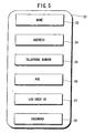
- FIG.5 illustrates one example of log user information.
- the log user information includes, for instance, name 23, address 24, telephone number 25, age 26, log user ID 27, and password 28.
- the password 28 is one that is established at the time of log user registration, in which input of the password 28 is desired when the log user performing login, then, it becomes possible to judge as identical person when the password 28 is correct. It is assumed in the present embodiment that the nonvolatile memory 21 of being recorded the log user information is used as authentication card. Hereinafter, the nonvolatile memory 21 is called as authentication card 21.
- FIG.6 is one in which flowchart of this login processing is illustrated.
- the log collection terminal device allows a monitor unit that is not illustrated to display a login screen 29 as illustrated in FIG.7 for example.
- the log collection terminal device allows login screen 29 to display user ID display column 30 and password input column 31.
- the user ID display column 30 displays ID that is recorded in the authentication card 21 (nonvolatile memory 21 ).
- the password input column 31 is one to which the log user inputs the password 28.
- the log collection terminal device ascertains whether the log user has the authentication card in STEP S18 at the same time of processing of STEP S14. Namely, the log collection terminal device judges whether the log user has the authentication card 21 depending on detection whether the authentication card 21 is connected to the external memory control unit 18, and whether the log user information is recorded within the authentication card 21.
- STEP S15 when the log collection terminal device judges that the log user does not have the authentication card 21, the log collection terminal device regard the log user as new one, and then allowing processing of this state to move toward new registration processing of STEP S16. While, when the log collection terminal device judges that the log user has the authentication card 21 at STEP S15, the log collection terminal device judges that the log user have been already registered as the log user, and then the log collection terminal device allows the processing of this state to move toward processing of STEP S17. When proceeding to processing of STEP S17, the log collection terminal device inputs therein log user ID 27 from the authentication card 21 and then allowing the log user ID 27 to be displayed on the user ID display column 30.
- the log collection terminal device takes in password 28 input from the log user, further the log collection terminal device, in STEP S19, conducts verification of the password 28.
- the password 28 is input via input unit such as keyboard and so forth.
- the log collection terminal device allows the processing of this state to move toward processing of STEP S20, and then conducting login failure processing. In this login failure processing, it is possible to urge input of the password 28 again or it is possible to execute processing of terminating it as login failure as it is. It should be noted that, it is assumed in the present embodiment that login is terminated as login failure processing of STEP S20.
- the log collection terminal device judges that user authentication is completed, and then executing login success processing as processing of STEP S21, after that, the log collection terminal device terminates the login processing. It should be noted that in the login success processing in STEP S21, it could be considered that, for instance, screen display for indicating success in login, and so forth.
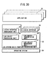
- FIG.8 illustrates connection of programs for realizing log collection and log transmission in the log collection terminal device.
- a login interface provided with function for forming basic structure of the log and function for generating desired log information from the basic structure of the log which the login interface hierarchically constructs log, and then transmitting hierarchically constructed log information to the log server 7, or independently managing the log information in every application program.
- Program illustrated in FIG.8 comprises an application 32 for utilizing the log system, a log system basic function processing unit 33 for providing basic function of the log collecting/analyzing system and an operating system 39 for operating the log collecting/analyzing system, in which upper and lower side relationship illustrated in FIG.8 means that function positioned at upper order utilizes function of low order.
- the log system basic function processing unit 33 is separated into some processing units.
- Login interface management unit 34 manages login interface 38.
- the login interface 38 which is independently defined by the log collection service utilizing companies 9 to 12 for utilizing collected log information executes processing for outputting log that is specialized in accordance with respective log service.
- the login interface management unit 34 initializes desired login interface 38 to provide.
- log object processing unit 35 is a unit for controlling function of the log object as being basics of the log.
- Log object transmission unit 36 is a unit for controlling processing of transmitting log information to the log server 7.
- Log object management unit 37 is a unit for managing log itself such as storage area of log object, elimination processing thereof and so forth. For instance, when executing storage of logs, the log object management unit 37 specifies appropriate position for the storage. Also, on the occasion of elimination of unnecessary log, the log object management unit 37 controls the elimination.
- FIG.9 illustrates configuration of log object 40.
- Log object 40 is composed of log management information 41 and log data 1 to 4 (42 to 45).
- the log management information 41 is one in which information for informing background of the log object 40 is recorded.
- the log data 1 to 4 ( 42 to 45) are ones in which specific log information generated by the login interface 38 is recorded.
- the log object 40 is capable of including a plurality of log data. It should be noted that FIG.9 illustrates one example thereof.
- FIG.10 illustrates internal configuration of the log management information 41.
- the log management information 41 is composed of log application ID 46 and log user ID 47.
- the log application ID 46 is identification information that is utilized in order to specify application of controlling to use the log collecting/analyzing system.
- the log user ID 47 indicates identification information of being utilized in order to indicate that the log belongs to which user.
- FIG.11 illustrates configuration of the log data 1 ( 42 ), and such log data 1 ( 42 ) is divided into two of node and element with tree structure.
- the node is capable of including nodes or elements. It should be noted that the node can not be utilized as terminal device. While, the element is capable of being utilized as terminal device and capable of including arbitrary data.
- the node 48 is root node, and the front of log data refers to front node of the root node 48.
- the node 49 is one for including element 50 positioned at low order.
- the log data 1 to 4 ( 42 to 45 ) are capable of adopting arbitrary log structure due to management of such tree structure.
- XML eXtensible Markup Language
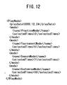
- FIG.12 illustrates one example thereof.
- This FIG.12 illustrates example of being recorded selected play mode and the number of utilization of the play mode in a certain application such as video game and so forth.
- Tag ⁇ play Date> in FIG.12 indicates data when the user takes the log, and tag ⁇ mode> records play mode name that is used in this case (indicated by tag ⁇ name>) and the number of use thereof (indicated by tag ⁇ selected Times>).
- This example indicates that record is one in which Practice Mode is used three times at 2000, 12, 24.
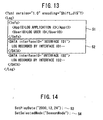
- FIG.13 illustrates example of the case in which log object illustrated in FIG.9 is expressed as XML.
- ⁇ info> tag describes both log application ID (hereinafter referred to as log appli. ID 46) for indicating log application program (hereinafter referred to as log appli.) that generates the log object and log user ID 47 indicating user to become object of the log.
- the log related to the login interface is described in ⁇ DATA> tag 52.
- the ⁇ DATA> tag 52 as being example illustrated in FIG.13 describes that this tag is one which is generated by login interface indicated by interface ID1, further, on the inside of the ⁇ DATA> tag 52 , which describes the log itself constituted by login interface indicated by the interface ID1.
- the shape of the ⁇ DATA> tag 52 at this time becomes one illustrated in FIG.11 . Accordingly, if following these tags, it becomes possible to retrieve desired data. It should be noted that these ID are utilized in order to homologize analysis interface used on the occasion that analysis of the log is executed onto the log at the log server 7 later.
- tree structure of the log illustrated in FIG.11 is also capable of being output directly from respective applications, however, when preparing such configuration in every application, there may be problems that programs for forming tree structure are redundant, in addition, since pre-arrangements for recording log is large, development efficiency decreases.
- the present embodiment since development of program for forming tree structure in every respective application causes bad efficiency, therefore, the present embodiment enhances development efficiency of the application by providing program for forming tree structure as library.
- the present invention separates functions such as preparation, storage and so forth of basic structures of the log as basic function, further designing and mounting specific recorded part of the log at the application side that utilizes its basic function as login interface, whereby the present invention realizes effective log collecting/analyzing system capable of flexibly coping with various kind of uses.
- the login interface 38 illustrated in FIG.8 provides above-described log data 1 to 4.
- the login interface 38 described in the present embodiment is a program that is designed and mounted in order to collect and record logs, in which the login interface 38 functions as API (Application Programming Interface) between the application 32 illustrated in FIG.8 and the log system basic function processing unit 33.
- This library with the login interface 38 mounted allows log basic library that is one for preparing basic tree structure on the inside thereof to access, in which the log basic library outputs the result and receives in accordance with determined format, in addition, the log basic library hierarchically constructs log and then designing and mounting specialized log for the application program.
- the login interface 38 is specifically designed depending on necessary log contents, and one example thereof is illustrated in FIG.14 .
- API 53 is one in which date of use is recorded.
- the application 32 becomes possible to generate ⁇ Play Date> tag by accessing this API 53.
- the application 32 becomes possible to prepare ⁇ mode> tag and the following structure bodies by accessing the API 53.
- this API 54 device is slightly added in this mounting in that when mode with the same name is used, the number of times of use is added to record by 1.
- the side of the application 32 can manage data desired to record, and also the side of the login interface 38 is capable of managing the data desired to record, thus any of them is capable of recording necessary data.
- Log objects are recorded in nonvolatile storage area such as HDD 20, flash memory and so forth.
- log objects are recorded in authentication card 21.
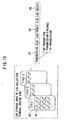
- the log object is managed in every application unit in which the log object is used. Namely, the log object is managed on its storage area in every application with shape of title 1, title 2, ⁇ illustrated in FIG.15 , in which the logs are registered to those respective areas. For instance, log storage area 55 illustrated in FIG.15 is managed for the sake of application of title 1, and log 56 is registered to the area 55 in that the application utilizes the log 56.
- the log object is stored with shape of structure as illustrated in right side of FIG.15 .
- the log object is constituted by a transmission flag 57, a log object size 58 and a log object 59.
- the transmission flag 57 is one that records conditions when transmitting logs to the log server 7, thus the transmission flag 57 has three conditions of, for instance, un-transmitted, finished transmission and in transmission.
- the un-transmitted means that the log is not transmitted to the log server yet.
- the finished transmission means that the log is already transmitted to the log server 7 .
- the in transmission means that transmission of the log is not completed to the log server 7 caused by interruption of the transmission by cause of some kind in the last time transmission of the log.
- the log of un-transmitted or the log in transmission is transmitted to the log server 7.
- the log storage area 55 increases to accumulate the logs, however, about the finished transmission logs, it is possible to remove the logs of being finished transmission. For this reason, memory areas such as HDD 20, flash memory and so forth are not pressured.
- the log collection terminal device allows utilization termination processing of the log collecting/analyzing system to execute before termination processing (processing of STEP S5 ) of the application as processing of STEP S4 illustrated in FIG.3 .
- the log collection terminal device forcibly stores therein the log object in use, and/or executes use termination processing of log storage area, and so forth in safety.
- the log collection terminal device executes termination processing of the log application itself at STEP S5 after termination of these processing, and thus terminating operation of the log collection terminal device itself.
- the log server 7 is composed of an image/sound control unit 60, a CPU 61, a communication control unit 62, a media control unit 63, a RAM 64, an input control unit 65 and a HDD 66 as principal configuration elements, in which these elements are connected via bus 67.
- the image/sound control unit 60 controls image output for monitor unit that is not illustrated and voice output for speaker and so forth or controls inputs from video camera and microphone.
- the CPU 61 takes charge of control for program on the log server 7 and/or control of equipment connected by the use of bus 67.
- the communication control unit 62 is connected to the networks 5, 8 illustrated in FIG.1 and then the communication control unit 62 controls communication executed between the networks 5 and 8 and another part, and being utilized reception of the logs and so forth.
- the media control unit 63 controls media drive that is not illustrated, and then the media control unit 63 inputs therein signals from external media such as CD-ROM, DVD and so forth equipped with the media drive, in addition, the media control unit 63 allows signal writing and so forth to be executed to external media such as CD-RW and so forth.
- the RAM 64 is a unit for storing program, data and so forth for operating at the log server 7.
- the input control unit 65 controls input unit to be user interface such as keyboard, mouse that are not illustrated at the log server 7.
- the HDD 66 is large capacity storage area for recording log information managed at the log server 7 and/or for recording analyzed result and so forth.
- FIG.17 illustrates outline configuration of program for realizing reception-analysis of logs in the log server 7.
- the log server independently manages log information received from the log collection terminal device for every individual application program, and then the log server pulls out necessary information from the log information to analyze, after that, the log server stores analyzed result in desired form.
- Program illustrated in FIG.17 is mainly provided with an operating system 74, a log server function processing unit 68 and a log analysis interface 70 and relationship between upper and lower in the drawing means that upper rank section utilizes function of lower rank section.
- the log server function processing unit 68 is composed of a log analysis interface management unit 69, a log object analysis unit 71, a log object reception unit 72 and a log analyzed result management unit 73.
- the log analysis interface management unit 69 manages log analysis interface 70.
- the log server 7 is capable of pulling out the log analysis interface 70 necessary for analysis in such a way as to go through the log analysis interface management unit 69.
- the log analysis interface 70 is an interface for analyzing log information received from the log collection terminal device. Such log analysis interface 70 is designed and mounted with form corresponding to the login interface 38 used at the system of log collection terminal device side.
- the log object analysis unit 71 analyzes logs received by the log server 7.
- the log object reception unit 72 is one that controls function for receiving logs transmitted from the log collection terminal device.
- the log analyzed result management unit 73 stores therein result of analysis analyzed in the log object analysis unit 71, in addition, the log analyzed result management unit 73 provides result of analysis to the log collection service utilizing companies 9 to 12 .
- the above-described log server 7 receives the above-described log and then the log server 7 allows database to be prepared in order to store and manage the result of analysis analyzed by the log server 7.
- a log management database, a log storage database and a log analyzed result management database are prepared as database.
- FIG.18 to FIG.23 illustrate configurations of these databases. It should be noted that these databases are managed on the log storage area illustrated in FIG.1 .
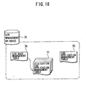
- FIG.18 illustrates outline configuration of log management database to be one of these databases.
- the log management database is composed of a log user management table 76, a utilization log application management table 77 and a log application management table 78.
- the log user management table 76 manages user information of being subjected to log service.
- This table contents are constituted from log user ID, name, age, address, telephone number, log storage table name and utilization log application management table name, as illustrated in the log user management table 76 of FIG.19A . Since such name, age, address, telephone number and so forth are items of forming as one example, when detailed information as personal information is desired, it is possible to cope with such case by increasing items if necessary.
- the log storage table name is one in which when the log server 7 receives the log, storage position of the log is specified within the log storage table name. The log is stored and managed in every log user.
- the log management information of the log object illustrated in FIG.10 is utilized here.
- the log appli. ID described in the log object is used in order to classify the log application, in addition, the log user ID is used in order to classify the log users.
- the utilization log application management table name illustrated in FIG.19B specifies utilization log application management table 77 in order to manage log application of being used by the user.
- This utilization log application management table 77 is constituted by the log appli. ID and the final log reception the date and time as illustrated in FIG.19B .
- the utilization log application management table 77 is prepared in every log user, and the utilization log application management table 77 manages that the log user utilizes from which log application. Accordingly, it becomes possible to immediately know that the log user utilizes which log application by referring to this table.
- log user information on the log user management table 76 is prepared by new log user registration. For instance, new log user registration processing in STEP S16 illustrated in FIG.6 provides the log user information.
- the log application management table 78 manages log application of executing log service.
- the configuration of the log application management table 78 is illustrated in FIG.19C , and the log application management table 78 is composed of log appli. ID, licensee name, authentication data, log storage table name, the number of analysis table, log analyzed result management table name and flag in service.
- the log appli. ID is number numbered uniquely to application that uses the log collecting/analyzing system.
- the licensee name indicates a person who prepares the log application or company name thereof.
- the authentication data is utilized in order to ascertain other person who provides the log on the occasion of providing the log.
- the log storage table name indicates log storage table for log application in order to manage log registered in log application.
- the number of analysis table is one which indicates the number of existing how many analyzed result table in the result of analyzing by log application.
- the log analyzed result management table name manages table that stores log analyzed result, and the log analyzed result management table name is generated in every log application.
- the flag in service is one which controls whether the log application is capable of being utilized. The flag is utilized in order to indicate service conditions that, for instance, service is already terminated.
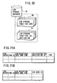
- FIG.20 illustrates outline configuration of log storage database 79.
- the log storage database 79 is composed of a log storage table for the user 80 and a log storage table for the log application 81.
- the log storage table for the user 80 when the log user transmits log to the log server 7, is a position in which the log is stored first.
- Configuration of the log storage table for the user 80 includes a log reception ID, a log reception the date and time, a utilization log application ID and logs.
- the log reception ID is number numbered uniquely in every log reception.
- the log reception the date and time is one in which the date and time when the log is received is recorded.
- the utilization log application ID indicates that recorded log is utilized what log application. Further, the log object itself is recorded in the log shown in FIG.21A .
- the log storage table for log application 81 is one that manages log registered in the log application.
- the log storage table for log application 81 is utilized for analysis of the log. Analysis of the log is executed in every log application, however, determination whether which log is analyzed is made while referring to this log storage table for log application 81.
- the log storage table for log application 81 is constituted by log reception ID, log reception the date and time and log user ID as illustrated in FIG.21B . In analysis of the log, it is possible to specify which log of the log storage table for user 80 according to the log reception ID and the log user ID to analyze the specified log.
- FIG.22 illustrates outline configuration of log analyzed result management database.
- the log analyzed result management database 82 is composed of log analyzed result management table 83 and analyzed result storage table by login interface 84.
- the log analyzed result management table 83 is composed of log analysis interface ID and log analyzed result storage table name.
- the log analysis interface ID indicates interface for analyzing the log and corresponds to ID of the login interface 38 used in the side of log collection terminal device.
- the log analysis interface ID is one to which function for accessing necessary information is mounted, in which necessary information is accessed to be pulled up from the log that is generated by login interface at the side of the log collection terminal devices 1 to 4.
- the log analysis interface executes extraction of data, conversion and record processing in order to record such analyzed result on the database.
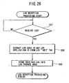
- processing illustrated in FIG.25 is one that is mainly conducted by CPU 61 of the log server 7.
- initialization of the log server system is executed.
- necessary initialization of database manager is executed in order that the log server system uses the database and then necessary initialization of computer resources for the log server 7 that requires the above initialization of database manager.
- the log server system becomes log reception condition of receiving signal (log information) transmitted from the log collection terminal device. Here, stand-by condition continues until log reception is completed.
- the log server 7 executes analysis processing of received log.
- Analysis processing of log in STEP S24 executes respective appropriate analyses according to log analysis interface 70 that specifies contents of the logs.
- the log server system executes termination check in processing of STEP S25.
- the log server system returns to processing of STEP S23 to come into log reception condition.
- the log server system judges as being log server system termination, then processing proceeding to STEP S26 to execute termination processing of the log server system here. Termination of the log server system indicates termination of computer resources and database manager that the log server system uses.
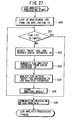
- the log storage area 6 is capable of being specified by the log user ID as well as the log appli. ID.
- Processing reads out first the log user management table 76 of the log management database 75. Then, identification of the log storage table for user 80 is executed by using the log user ID. Received log is stored in the log storage table for user 80, and, at this time, log reception ID is obtained.
- the log reception ID is a number for uniquely determining the log.
- utilization log application management table 77 records the date and time of receiving log and the log appli. ID in such a way as to match the former with the later.
- processing reads out log application management table 78 of log management database 75 .
- identification of log storage table for log application by using the log appli. ID In storage for the table, log reception ID, log reception the date and time and log user ID are recorded.
- the log reception ID uses log reception ID that is obtained when storing log in the log storage table for user 80.
- the log reception the date and time uses the same reception the date and time that provided for the user.
- Log reception processing is completed after above described processing.
- processing pulls up log list of being registered log on the basis of the log appli. ID.
- log list registered according to the log appli. ID is pulled up from the log storage table for log application 81 of the log storage database 79 illustrated in FIG.20 .
- the log list is prepared on the basis of the log appli. ID because analysis in every analysis unit is executed in every log application unit.
- processing of STEP S31 the log server 7 ascertains whether the log list is empty.
- FIG.28 illustrates flow of the case that log collection service utilizing companies 9 to 12 to be log utilization terminal devices require log analyzed result acquisition to the log server 7.
- login processing of the log collection service utilizing companies 9 to 12 for the log server 7 is executed.
- the log collection service utilizing company transmits name of log collection utilization to the log server 7, namely, transmits licensee name and authentication data to the log server 7 via the internet 8 illustrated in FIG.1 .
- the log server 7 executes authentication processing of the log collection service utilizing companies by using these information.
- processing of STEP S38 judges authentication result, when authentication data is judged as effective data, processing proceeds to STEP S39.
- the authentication data is of no effect, judgment that login processing is failure is input to the log server 7 and then log analyzed result acquisition processing is terminated.
- STEP S38 when the log collection service utilizing company succeeds in login, the log collection service utilizing company becomes log analyzed result acquisition feasible state.
- STEP S39 the log collection service utilizing company requires log analyzed result of being desired to obtain. Namely, the log collection service utilizing company specifies login interface ID and then transmitting the login interface ID. Thereupon, the analyzed result is retrieved in the log server 7 and then processing of STEP S40 provides transmission of retrieval result for the log collection service utilizing company. Then, processing of STEP S41 permits termination judgment of the log analyzed result acquisition processing. When the log analyzed result is necessary yet, processing returns to processing of STEP S39, then processing of STEP S39 to STEP S41 are repeated. Here, when being judged as acquisition termination, the log analyzed result acquisition processing is terminated.
- login interface ID which is capable of being specified is limited to login interface 38 established by the log collection service utilizing company, when another login interface 38 is specified, no analyzed result is returned.
- the log server 7 executes processing of login requirement from the log collection service utilizing companies 9 to 12. Namely, the log server 7 acquires licensee name and authentication data.
- the log server 7 pulls out authentication data corresponding to licensee name from the log application management table 78 illustrated in FIG.18 .
- the log server 7 judges whether login is effective or of no effective on the basis of authentication data stored therein and authentication data from the log collection service utilizing company.
- log server 7 When being judged as effective authentication data, provision processing of the log analyzed result is started. Namely, in processing of STEP S46, log server 7 acquires corresponding log analyzed result management table 83 to received licensee name from the log application management table 78 illustrated in FIG.19C . Then, in processing of STEP S47, the log server 7 receives login interface ID transmitted from the log collection service utilizing company. Next, in processing of STEP S48, the log server 7 reads out analyzed result from both received login interface ID and log analyzed result management table. Then, the log server 7 transmits read out result at processing of next STEP S49 to the log collection service utilizing company.
- the log server 7 judges whether read out processing of analyzed result is terminated by the log collection service utilizing company. The log server 7 judges that read out processing of analyzed result is not terminated in this STEP S50, processing returns to processing of STEP S47, and then read out processing of log analyzed result repeated again. When terminating the processing, the log server 7 executes log analyzed result acquisition termination processing. In addition, in processing of STEP S44, when the log server 7 judges that login is of no effect, the log server 7 informs the log collection service utilizing company that login results in failure at STEP S45, and then log analyzed result acquisition processing at the side of the log server 7 is terminated.
- log collecting/analyzing system is constituted in which log collection terminal devices 1 to 4 collect logs to generate desired log information, and then the log information is transmitted to the log server 7, and then the log server 7 analyzes received log information, then the log collection service utilizing companies 9 to 12 receive the analyzed result.
- login interface management unit 34 of log system basic function processing unit 33 manages login interface 38 prepared independently from the above described application 32 and then the application 32 calls the login interface 38, then the login interface 38 generates log information.
- log collection service utilizing company it is preferable that hardware for acquiring log analyzed result possesses the same function as that of log collection terminal devices 1 to 4 as illustrated in FIG.2 or it is preferable that hardware for acquiring log analyzed result possesses configuration of server type as illustrated in FIG.16 . Then, as for display of acquired analyzed result, there is no particular limitation, thus it is possible to use freely.
- Log analyzed result is defined beforehand with specified form in accordance with log collection service utilizing company.
- function of log collecting/analyzing system is divided into two functions in which a function is one for collecting log information, and the other function is one for analyzing collected log information, further, the function for collecting log information belongs to client terminal device, while the function for analyzing the collected log information belongs to log server, whereby it becomes possible to specifically define log collection function, thus it is possible to collect more detailed log.
- a function is one for collecting log information
- the other function is one for analyzing collected log information
- the function for collecting log information belongs to client terminal device
- the function for analyzing the collected log information belongs to log server, whereby it becomes possible to specifically define log collection function, thus it is possible to collect more detailed log.
- the useful information can be obtained by the present invention. For that reason, it is possible to make use of result of log analysis for development of the game while performing feedback of result of log analysis.
- login interface since it is possible to independently define login interface for the sake of log collection, mounting of login interface capable of reuse becomes possible according to form of log. For instance, it is one in which user's taste is collected, and so forth.
- login interface in relation to certain application is capable of being replaced with the same login interface, accordingly, the same login interface is capable of being utilized at the application, thus it becomes possible to improve development efficiency for the sake of log collection.
Description
- This application is related to
Japanese Patent Application No. 2001-167815 No. 2002-8278 filed on January 17, 2002 - The present invention relates to a log collecting/analyzing system, a method of log collection, a log collection program, a method of log analysis, a log analysis program, a log collecting device, a log analyzing device, a log collection terminal device and a log server, which comprises separated functions of collecting log information and analyzing collected log information, and in which the log information is collected at client side and transmitted to server side, and the server side stores the log information to analyze.
- Conventional log collecting/analyzing system is used for the purpose of observing something, in a system for providing certain service. For instance, if the log collecting/analyzing system is applied to some on-line system, it is possible to ascertain how unfair access, fault of system or so forth occurred by analyzing log. In addition, if the log collecting/analyzing system is applied to WWW (World Wide Web) server, it is possible to record details that what-like client referred to, when, and what-like contents by analyzing log. And, as a result, it becomes possible to learn interest level of the user on the contents for example.
- However, in these conventional log collecting/analyzing systems described-above, when contents for servicing are determined first, contents for observing are also fixed depending on the determined contents for servicing. And, as a result, collected log information requires specialized analysis system for log. Accordingly, an analyzing system for observation log at the on-line system is entirely different from an analyzing system for log of the WWW server for instance.
- In addition, as for method of log collection itself, exclusive design and mounting are provided in every service system. For this reason, although basic function of collecting log is only desired, subtle differences are generated on log collection items. As a result, exclusive design and mounting is required for every service as for the basic collecting system.
- In
addition, document EP-A-0 913 774 discloses a managing computer for a plurality of computers connected via a network that acquires log information and event information from any of said plurality of computers and stores operation definition information used to define a schedule of process operations executed in the plurality of computers in relation to the log information and the event information into a database. - It is an object of the present invention to provide a log collecting/analyzing system, a method for log collection, a log collecting program, a method for log analysis, a log analysis program, a log collecting device, and a log analyzing device, all of which are capable of performing flexible log collection and analysis without being fixed to a log system as before.
- According to the present invention, the above objects are achieved by the claimed matter according to the independent claims.
- Advantageous further developments of the invention are subject of the accompanying dependent claims.
- The above and other features will be better understood from the exemplary embodiments described below, taken together with the drawings, of which:
-
FIG.1 is a block diagram illustrating the whole configuration of a log collecting/analyzing system; -
FIG.2 is a block diagram illustrating configuration example of a log collection terminal device; -
FIG.3 is a flowchart illustrating flow of log system processing at the log collection terminal device; -
FIG.4 is a flowchart illustrating flow of initialization of a log system; -
FIG.5 is a view illustrating one example of log user information; -
FIG.6 is a flowchart illustrating login processing; -
FIG.7 is a view illustrating display example of login screen; -
FIG.8 is a view illustrating configuration of a log system at the side of the log collection terminal device for log collection; -
FIG.9 is a view illustrating configuration of log object; -
FIG.10 is a view illustrating internal structure of management information of log; -
FIG.11 is a chart of tree structure illustrating configuration example oflog data 1; -
FIG.12 is a view illustrating an example of being represented about log data by using XML (eXtensible Markup Language); -
FIG.13 is a view illustrating an example of being represented about log object by using XML; -
FIG.14 is a view illustrating an example of API (Application Programming Interface) for forming log data; -
FIG.15 is a view illustrating storing method of log object; -
FIG.16 is a block diagram illustrating configuration example of log server; -
FIG.17 is a view illustrating configuration of log system at the side of the log server; -
FIG.18 is a view illustrating configuration of management database of log; -
FIG.19A illustrates configuration of management database of log: a view illustrating management table of log user; -
FIG.19B illustrates configuration of management database of log: a view illustrating management table of utilization of log application; -
FIG.19C illustrates configuration of management database of log: a view illustrating management table of log application; -
FIG.20 is a view illustrating configuration of log storage database; -
FIG.21A illustrates configuration of log storage database: a view illustrating log storage table for the user; -
FIG.21B illustrates configuration of log storage database: a view illustrating log storage table for log application; -
FIG.22 is a view illustrating configuration of management database of log analyzed result; -
FIG.23 illustrates configuration of management database of log analyzed result: a view illustrating management table of log analyzed result; -
FIG.24 is a view illustrating an example of storage table of log analyzed result; -
FIG.25 is a flowchart illustrating flow of log server system; -
FIG.26 is a flowchart illustrating flow of reception of log; -
FIG.27 is a flowchart illustrating flow of log analysis; -
FIG.28 is a flowchart illustrating flow of acquisition of log analyzed result of utilizing company side of log collection service; -
FIG.29 is a flowchart illustrating flow of acquisition of log analyzed result at log server side; and -
FIG.30 is a view illustrating another configuration of log system at log collection terminal device. - Preferred embodiments of the invention are described in detail below, with reference made to relevant accompanying drawings. Specific embodiment to which the present invention is applied will be described in detail referring to accompanying drawings below.
- The present embodiment provides entirely new example of log collecting/analyzing system in which client side collects log information and transmits the collected log information to server side, and the server side stores therein the transmitted log information to analyze. Namely, the present invention separates function of log collecting/analyzing system into two functions of collecting log and storing/analyzing the collected log in which the client side collects logs while the server side stores and analyzes the logs.
- In addition, function of the client side is to establish basic structure of log and then generating desired log information from the basic structure of log. On the other hand, function of the log server is to execute storage-analysis of the received log information and then analyzing the log information in every application program.
- In the fist place, rough flow of log collection, analysis and provision in the log collecting/analyzing system will be described.
-
FIG.1 illustrates the whole configuration of the log collecting/analyzing system. Log collectionterminal device devices 1 to 4 of being client terminal device devices to which client side software and client side hardware for collecting log are provided are connected to network 5 respectively. It should be noted that the log collection terminal device is capable of being added to increase without limiting the number of piece by sharing thenetwork 5. - In the log collecting/analyzing system illustrated in
FIG.1 , the log collectionterminal device devices 1 to 4 collect logs and then store therein logs temporarily. The log collectionterminal device devices 1 to 4 transmit log information that is collected and stored therein temporarily by the log collectionterminal device devices 1 to 4 towardlog server 7 via thenetwork 5. Thelog server 7 is provided withlog storage area 6 for storing therein received log information. Then, thelog server 7 stores the log information transmitted from the log collectionterminal device devices 1 to 4 in thelog storage area 6. In addition, thelog server 7 takes out the log information stored in thelog storage area 6 and then executes analysis processing of the log information, before storing the analyzed result in thelog storage area 6 again. - It should be noted that respective procedures for analysis processing executed by the
log server 7 are defined by log collectionservice utilizing companies 9 to 12. In addition, design and mounting are established so that collection program when conducting log collection and analysis processing correspond to log collection side and log analysis side respectively. - Here, consideration is made in connection with the case that the log collection
service utilizing companies 9 to 12 require analyzed result of log. At this time, to begin with, the log collectionservice utilizing companies 9 to 12 input acquisition requirement of the analyzed result to thelog server 7 via the network 8. Thelog server 7 which has received the acquisition requirement from the log collectionservice utilizing companies 9 to 12 authenticates the log collectionservice utilizing companies 9 to 12 connected to the network and then thelog server 7 adopts or rejectscompanies 9 to 12 on the basis of authentication result, after that, thelog server 7 transmits log analyzed result to the authenticated companies. It should be noted that a plurality of log collection service utilizing companies are connectable to thelog server 7 via the network 8. Then, thelog server 7 is capable of transmitting log analyzed result toward any of the log collectionservice utilizing companies 9 to 12 that are authenticated to be connected to thelog server 7 via the network 8. - Next, following description is one in which configuration of the log collection
terminal device devices 1 to 4 will be explained.FIG.2 illustrates internal configuration of one log collection terminal device. The log collection terminal device comprises an image/sound control unit 13, CPU (central calculation processing unit) 14, acommunication control unit 15,media control unit 16,RAM 17, externalmemory control unit 18,input control unit 19, HDD (magnetic recording medium) 20, as principal configuration elements, in which these respective elements are connected with each other via bus. - The image/
sound control unit 13 controls image output for monitor unit that is not illustrated and voice output for speaker and so forth or input from video camera and microphone. TheCPU 14 controls total operation of the log collection terminal device. Thecommunication control unit 15 that is connected to thenetwork 5 illustrated inFIG.1 controls communication of being executed between thecommunication control unit 15 and thenetwork 5. Themedia control unit 16 controls media drive which is not illustrated, in that themedia control unit 16 inputs therein signals from external recording media such as CD-ROM and/or DVD-ROM and so forth equipped with the media drive or themedia control unit 16 causes the external recording media to write signals. - The
HDD 20 records various kinds of programs containing program for realizing log collection processing of the present embodiment and/or various kind of data. TheRAM 17 stores therein program read out from theHDD 20 and/or data utilized on the occasion of execution of various kinds of processing. The externalmemory control unit 18 which is connected tononvolatile memory 21 existing at external part of the log collection terminal device and then theexternal memory unit 18 controls transmission/reception of the data as well as write/read of the data between the external memory control unit and thememory 21. Theinput control unit 19 controls input units to be user interface such as keyboard, mouse, and so forth that are not illustrated. - Next, flow of processing (principally, processing of application part according to the present invention) at the log collection terminal device will be explained using
FIG.3 . It should be noted that processing illustrated inFIG.3 is one that is mainly achieved by function of the CPU mounted on the log collection terminal device. First, as processing of STEP S1, the log collection terminal device provides initialization of log collecting/analyzing system illustratedFIG.1 in order to permit utilization of the log collecting/analyzing system. In this initialization, judgments are made in which the log collection terminal device ascertains log user in order that the log collection terminal device uses the log collecting/analyzing system illustrated inFIG.1 , and the log collection terminal device judges whether the log collection terminal device is capable of using the log collecting/analyzing system illustrated inFIG.1 , and so forth. When completing the processing, in the log collection terminal device, initialization of application is executed as processing of STEP S2. - When completing the initialization of the application, the log collection terminal device provides main processing (application main processing) of the application as processing of STEP S3. It should be noted that the application main processing will be described later. Then, the log collection terminal device, when completing the application main processing, executes processing in order to terminate utilization of the log collecting/analyzing system illustrated in
FIG.1 as processing of STEP S4. According to this termination processing, the log collection terminal device stores log information maintained in theRAM 17 for the sake of the log collecting/analyzing system into theHDD 20 and so forth, further the log collection terminal device conducts release of resources that are used for the log collecting/analyzing system. After that, the log collection terminal device conducts termination processing of the application of the present embodiment as processing of STEP S5. After that, the logcollection terminal devices 1 to 4 become condition in which the log collectionterminal device devices 1 to 4 are capable of being terminated. - Next, following description is one in which detail of processing for the sake of utilization of the log collecting/analyzing system of being conducted in STEP S1 of
FIG.3 is explained.FIG.4 illustrates a flowchart for initialization processing of the log collection terminal device for the sake of utilization of the log collecting/analyzing system. First, the log collection terminal device conducts login processing of the log user as processing of STEP S6. This login processing is necessary processing for identifying the user who uses the log collecting/analyzing system, and the processing informs the information concerning the user thus the user is grasped. - In ascertainment processing of STEP S6, when the user is not registered as a log user, log user registration processing is conducted in processing of STEP S7. In this registration, the log collection analysis terminal device ascertains whether double registration is conducted in this registration, or whether the user is unfair user, in such a way as to compare information registered beforehand with information input by the log user registration, and so forth. Then, in processing of STEP S8, when succeeding user registration, the log collection terminal device continues log system initialization. In this processing of STEP S8, user registration is not made by factor of some kind, the log collection terminal device interrupts log system initialization and then the log collection terminal device executes log system no use condition setting at processing of STEP S12, thereafter, the log collection terminal device concludes the log system initialization.
- On the other hand, in processing of STEP S8, when registration ascertainment as log user is succeeded, the log collection terminal device inputs therein log user information stored in, for instance, the
HDD 20 and/or thenonvolatile memory 21 as processing of STEP S9, further, the log collection terminal device inputs therein log system utilization title information as processing of STEP S10. - Then, the log collection terminal device ascertains whether the log system can be utilized as processing of STEP S11. It should be noted that this ascertainment is conducted to control period of using the log system. For instance, in cases where certain log service is established so as to provide service only one month, if, for instance, service period of the log collecting/analyzing system is concluded, it becomes not possible to transmit log to the
log server 7, therefore, the log collection terminal device ascertains whether the log collecting/analyzing system is capable of being used in order to forestall occurrence of such condition. - When judgment is one in which the log collecting/analyzing system can not be utilized in the judgment of STEP S11, operation of the log collection terminal device proceeds to processing of STEP S12, and then setting the log system into use prohibition condition. This use prohibition condition is that the log collection terminal device overrides records of log in the log collecting/analyzing system, and function of transmission of log for the
log server 7, and so forth. Thus, when the log collecting/analyzing system is set to the use prohibition condition, an application that employs the log collecting/analyzing system is capable of executing processing in the same way as that of normal function regardless of whether the log collecting/analyzing system is effective or ineffective, however, specific processing of recording of logs and/or transmitting of logs are not executed. Namely, the log collection terminal device realizes control of the use prohibition condition in such a way as to internally control whether processing of recording log and transmitting log is reflected. - On the other hand, when providing judgment that the log collecting/analyzing system is capable of being used at STEP S11, the log collection terminal device executes transmission processing of logs that are not transmitted yet as processing of STEP S13.
- The present invention is characterized in that it is possible to realize function of collecting log in off-line environment. Processing of STEP S13 relates to the function of collecting in off-line environment. Namely, when the log collection terminal device is always connected to the
network 5, it is possible to process surely transmission of the log to thelog server 7, while when thenetwork 5 is interrupted, or it is not possible to transmit log information for thelog server 7 side caused by obstacle of some kind, the log collection terminal device stores log information temporarily, and then, the log collection terminal device transmits log again when thenetwork 5 or thelog server 7 is restored to normal condition. Processing of STEP S13 is one in which retransmission function of the log is realized. - Next, as for information registered as log user information and registered position thereof are explained.
- If position of recording log user information is in nonvolatile recording media on the log collection terminal device, whichever position is recorded position, the position is permitted. For instance, it is possible to record the log user information on the
nonvolatile memory 21,HDD 20 illustrated inFIG.2 , or on writable media controlled by themedia control unit 16. However, when convenience and/or confidentiality are taken into consideration, recording on thenonvolatile memory 21 is effective because recording on nonvolatile memory is capable of being easily utilized to login processing at another log collection terminal device. It is assumed in the present embodiment that the log user information is recorded on thenonvolatile memory 21. In the present embodiment, each user is assigned anonvolatile memory 21 and each user uses thenonvolatile memory 21, whereby the log collection terminal device is capable of identifying respective log users.FIG.5 illustrates one example of log user information. The log user information includes, for instance,name 23,address 24,telephone number 25,age 26, loguser ID 27, andpassword 28. Thepassword 28 is one that is established at the time of log user registration, in which input of thepassword 28 is desired when the log user performing login, then, it becomes possible to judge as identical person when thepassword 28 is correct. It is assumed in the present embodiment that thenonvolatile memory 21 of being recorded the log user information is used as authentication card. Hereinafter, thenonvolatile memory 21 is called asauthentication card 21. - Next, as for login processing in STEP S6 illustrated in
FIG.4 is explained.FIG.6 is one in which flowchart of this login processing is illustrated. First, as processing of STEP S14, the log collection terminal device allows a monitor unit that is not illustrated to display alogin screen 29 as illustrated inFIG.7 for example. The log collection terminal device allowslogin screen 29 to display userID display column 30 andpassword input column 31. The userID display column 30 displays ID that is recorded in the authentication card 21 (nonvolatile memory 21). Thepassword input column 31 is one to which the log user inputs thepassword 28. - In addition, the log collection terminal device ascertains whether the log user has the authentication card in STEP S18 at the same time of processing of STEP S14. Namely, the log collection terminal device judges whether the log user has the
authentication card 21 depending on detection whether theauthentication card 21 is connected to the externalmemory control unit 18, and whether the log user information is recorded within theauthentication card 21. - In STEP S15, when the log collection terminal device judges that the log user does not have the
authentication card 21, the log collection terminal device regard the log user as new one, and then allowing processing of this state to move toward new registration processing of STEP S16. While, when the log collection terminal device judges that the log user has theauthentication card 21 at STEP S15, the log collection terminal device judges that the log user have been already registered as the log user, and then the log collection terminal device allows the processing of this state to move toward processing of STEP S17. When proceeding to processing of STEP S17, the log collection terminal device inputs therein loguser ID 27 from theauthentication card 21 and then allowing thelog user ID 27 to be displayed on the userID display column 30. - Next, the log collection terminal device, in STEP S18, takes in
password 28 input from the log user, further the log collection terminal device, in STEP S19, conducts verification of thepassword 28. It should be noted that thepassword 28 is input via input unit such as keyboard and so forth. When verification result of thepassword 28 in STEP S19 is that password input from the log user does not agree with the registered password, the log collection terminal device allows the processing of this state to move toward processing of STEP S20, and then conducting login failure processing. In this login failure processing, it is possible to urge input of thepassword 28 again or it is possible to execute processing of terminating it as login failure as it is. It should be noted that, it is assumed in the present embodiment that login is terminated as login failure processing of STEP S20. - When verification result of the
password 28 in STEP S19 is that password input from the log user agrees with the registered password, the log collection terminal device judges that user authentication is completed, and then executing login success processing as processing of STEP S21, after that, the log collection terminal device terminates the login processing. It should be noted that in the login success processing in STEP S21, it could be considered that, for instance, screen display for indicating success in login, and so forth. -
FIG.8 illustrates connection of programs for realizing log collection and log transmission in the log collection terminal device. In the present embodiment, there is provided a login interface provided with function for forming basic structure of the log and function for generating desired log information from the basic structure of the log which the login interface hierarchically constructs log, and then transmitting hierarchically constructed log information to thelog server 7, or independently managing the log information in every application program. - Program illustrated in
FIG.8 comprises anapplication 32 for utilizing the log system, a log system basicfunction processing unit 33 for providing basic function of the log collecting/analyzing system and anoperating system 39 for operating the log collecting/analyzing system, in which upper and lower side relationship illustrated inFIG.8 means that function positioned at upper order utilizes function of low order. - The log system basic
function processing unit 33 is separated into some processing units. Logininterface management unit 34 manageslogin interface 38. Thelogin interface 38 which is independently defined by the log collectionservice utilizing companies 9 to 12 for utilizing collected log information executes processing for outputting log that is specialized in accordance with respective log service. When theapplication 32 requires thelogin interface 38, the logininterface management unit 34 initializes desiredlogin interface 38 to provide. - On the inside of these programs, the log is managed in every unit of log object, and log
object processing unit 35 is a unit for controlling function of the log object as being basics of the log. Logobject transmission unit 36 is a unit for controlling processing of transmitting log information to thelog server 7. Logobject management unit 37 is a unit for managing log itself such as storage area of log object, elimination processing thereof and so forth. For instance, when executing storage of logs, the logobject management unit 37 specifies appropriate position for the storage. Also, on the occasion of elimination of unnecessary log, the logobject management unit 37 controls the elimination. -
FIG.9 illustrates configuration oflog object 40. Logobject 40 is composed oflog management information 41 andlog data 1 to 4 (42 to 45). Thelog management information 41 is one in which information for informing background of thelog object 40 is recorded. Thelog data 1 to 4 (42 to 45) are ones in which specific log information generated by thelogin interface 38 is recorded. In addition, thelog object 40 is capable of including a plurality of log data. It should be noted thatFIG.9 illustrates one example thereof. -
FIG.10 illustrates internal configuration of thelog management information 41. Thelog management information 41 is composed oflog application ID 46 and loguser ID 47. Thelog application ID 46 is identification information that is utilized in order to specify application of controlling to use the log collecting/analyzing system. In addition, thelog user ID 47 indicates identification information of being utilized in order to indicate that the log belongs to which user. - Next, as for configuration of the
log data 1 to 4 (42 to 45), which is explained using example ofFIG.11. FIG.11 illustrates configuration of the log data 1 (42), and such log data 1 (42) is divided into two of node and element with tree structure. The node is capable of including nodes or elements. It should be noted that the node can not be utilized as terminal device. While, the element is capable of being utilized as terminal device and capable of including arbitrary data. Thenode 48 is root node, and the front of log data refers to front node of theroot node 48. Thenode 49 is one for includingelement 50 positioned at low order. - The
log data 1 to 4 (42 to 45) are capable of adopting arbitrary log structure due to management of such tree structure. Here, in the present embodiment, XML (eXtensible Markup Language) is utilized as specification for defining this tree structure.FIG.12 illustrates one example thereof. ThisFIG.12 illustrates example of being recorded selected play mode and the number of utilization of the play mode in a certain application such as video game and so forth. Tag <play Date> inFIG.12 indicates data when the user takes the log, and tag <mode> records play mode name that is used in this case (indicated by tag <name>) and the number of use thereof (indicated by tag <selected Times>). This example indicates that record is one in which Practice Mode is used three times at 2000, 12, 24. - When extracting data from this log data, it is possible to retrieve desired data by following the tag. Here,
FIG.13 illustrates example of the case in which log object illustrated inFIG.9 is expressed as XML. In an example ofFIG.13 , <info> tag describes both log application ID (hereinafter referred to as log appli. ID 46) for indicating log application program (hereinafter referred to as log appli.) that generates the log object and loguser ID 47 indicating user to become object of the log. - In addition, the log related to the login interface is described in <DATA>
tag 52. Namely, the <DATA>tag 52 as being example illustrated inFIG.13 describes that this tag is one which is generated by login interface indicated by interface ID1, further, on the inside of the <DATA>tag 52, which describes the log itself constituted by login interface indicated by the interface ID1. The shape of the <DATA>tag 52 at this time becomes one illustrated inFIG.11 . Accordingly, if following these tags, it becomes possible to retrieve desired data. It should be noted that these ID are utilized in order to homologize analysis interface used on the occasion that analysis of the log is executed onto the log at thelog server 7 later. - Now, tree structure of the log illustrated in
FIG.11 is also capable of being output directly from respective applications, however, when preparing such configuration in every application, there may be problems that programs for forming tree structure are redundant, in addition, since pre-arrangements for recording log is large, development efficiency decreases. In the present embodiment, since development of program for forming tree structure in every respective application causes bad efficiency, therefore, the present embodiment enhances development efficiency of the application by providing program for forming tree structure as library. - In order to solve the above subject, the present invention separates functions such as preparation, storage and so forth of basic structures of the log as basic function, further designing and mounting specific recorded part of the log at the application side that utilizes its basic function as login interface, whereby the present invention realizes effective log collecting/analyzing system capable of flexibly coping with various kind of uses.
- Namely, in the present embodiment, the
login interface 38 illustrated inFIG.8 provides above-describedlog data 1 to 4. Thelogin interface 38 described in the present embodiment is a program that is designed and mounted in order to collect and record logs, in which thelogin interface 38 functions as API (Application Programming Interface) between theapplication 32 illustrated inFIG.8 and the log system basicfunction processing unit 33. This library with thelogin interface 38 mounted allows log basic library that is one for preparing basic tree structure on the inside thereof to access, in which the log basic library outputs the result and receives in accordance with determined format, in addition, the log basic library hierarchically constructs log and then designing and mounting specialized log for the application program. - Here, the
login interface 38 is specifically designed depending on necessary log contents, and one example thereof is illustrated inFIG.14 . In thelogin interface 38 illustrated inFIG.14 , API 53 is one in which date of use is recorded. At the side of theapplication 32, it becomes possible to generate <Play Date> tag by accessing this API 53. In addition, theapplication 32 becomes possible to prepare <mode> tag and the following structure bodies by accessing the API 53. It should be noted that, as for thisAPI 54, device is slightly added in this mounting in that when mode with the same name is used, the number of times of use is added to record by 1. Thus, according to mounting of thelogin interface 38 of the present embodiment, the side of theapplication 32 can manage data desired to record, and also the side of thelogin interface 38 is capable of managing the data desired to record, thus any of them is capable of recording necessary data. - Next, as for storage method of above described log object including logs will be described using
FIG.15 . Log objects are recorded in nonvolatile storage area such asHDD 20, flash memory and so forth. In the present embodiment, log objects are recorded inauthentication card 21. In addition, the log object is managed in every application unit in which the log object is used. Namely, the log object is managed on its storage area in every application with shape oftitle 1,title 2, ··· illustrated inFIG.15 , in which the logs are registered to those respective areas. For instance, logstorage area 55 illustrated inFIG.15 is managed for the sake of application oftitle 1, and log 56 is registered to thearea 55 in that the application utilizes thelog 56. - The log object is stored with shape of structure as illustrated in right side of
FIG.15 . Namely, the log object is constituted by atransmission flag 57, alog object size 58 and alog object 59. Thetransmission flag 57 is one that records conditions when transmitting logs to thelog server 7, thus thetransmission flag 57 has three conditions of, for instance, un-transmitted, finished transmission and in transmission. The un-transmitted means that the log is not transmitted to the log server yet. The finished transmission means that the log is already transmitted to thelog server 7. The in transmission means that transmission of the log is not completed to thelog server 7 caused by interruption of the transmission by cause of some kind in the last time transmission of the log. When transmitting the logs, the log of un-transmitted or the log in transmission is transmitted to thelog server 7. In addition, thelog storage area 55 increases to accumulate the logs, however, about the finished transmission logs, it is possible to remove the logs of being finished transmission. For this reason, memory areas such asHDD 20, flash memory and so forth are not pressured. - Next, as for termination processing at the side of log collection terminal device will be explained. In the side of the log collection terminal device, when application is made to terminate, first, it is necessary to terminate utilization of the log collecting/analyzing system. This processing is necessary one in order that the log is recorded without contradiction. For this reason, the log collection terminal device allows utilization termination processing of the log collecting/analyzing system to execute before termination processing (processing of STEP S5) of the application as processing of STEP S4 illustrated in
FIG.3 . Specifically, the log collection terminal device forcibly stores therein the log object in use, and/or executes use termination processing of log storage area, and so forth in safety. The log collection terminal device executes termination processing of the log application itself at STEP S5 after termination of these processing, and thus terminating operation of the log collection terminal device itself. - Next, as for configuration of
log server 7 side will be explained. Thelog server 7, as illustrated inFIG.16 , is composed of an image/sound control unit 60, aCPU 61, acommunication control unit 62, amedia control unit 63, aRAM 64, aninput control unit 65 and aHDD 66 as principal configuration elements, in which these elements are connected viabus 67. - The image/
sound control unit 60 controls image output for monitor unit that is not illustrated and voice output for speaker and so forth or controls inputs from video camera and microphone. TheCPU 61 takes charge of control for program on thelog server 7 and/or control of equipment connected by the use ofbus 67. Thecommunication control unit 62 is connected to thenetworks 5, 8 illustrated inFIG.1 and then thecommunication control unit 62 controls communication executed between thenetworks 5 and 8 and another part, and being utilized reception of the logs and so forth. Themedia control unit 63 controls media drive that is not illustrated, and then themedia control unit 63 inputs therein signals from external media such as CD-ROM, DVD and so forth equipped with the media drive, in addition, themedia control unit 63 allows signal writing and so forth to be executed to external media such as CD-RW and so forth. TheRAM 64 is a unit for storing program, data and so forth for operating at thelog server 7. Theinput control unit 65 controls input unit to be user interface such as keyboard, mouse that are not illustrated at thelog server 7. TheHDD 66 is large capacity storage area for recording log information managed at thelog server 7 and/or for recording analyzed result and so forth. - Next,
FIG.17 illustrates outline configuration of program for realizing reception-analysis of logs in thelog server 7. In the present embodiment, the log server independently manages log information received from the log collection terminal device for every individual application program, and then the log server pulls out necessary information from the log information to analyze, after that, the log server stores analyzed result in desired form. - Program illustrated in
FIG.17 is mainly provided with anoperating system 74, a log serverfunction processing unit 68 and alog analysis interface 70 and relationship between upper and lower in the drawing means that upper rank section utilizes function of lower rank section. The log serverfunction processing unit 68 is composed of a log analysisinterface management unit 69, a logobject analysis unit 71, a logobject reception unit 72 and a log analyzedresult management unit 73. - The log analysis
interface management unit 69 manageslog analysis interface 70. Namely, thelog server 7 is capable of pulling out thelog analysis interface 70 necessary for analysis in such a way as to go through the log analysisinterface management unit 69. Thelog analysis interface 70 is an interface for analyzing log information received from the log collection terminal device. Suchlog analysis interface 70 is designed and mounted with form corresponding to thelogin interface 38 used at the system of log collection terminal device side. - The log
object analysis unit 71 analyzes logs received by thelog server 7. The logobject reception unit 72 is one that controls function for receiving logs transmitted from the log collection terminal device. The log analyzedresult management unit 73 stores therein result of analysis analyzed in the logobject analysis unit 71, in addition, the log analyzedresult management unit 73 provides result of analysis to the log collectionservice utilizing companies 9 to 12. - In addition, the above-described
log server 7 receives the above-described log and then thelog server 7 allows database to be prepared in order to store and manage the result of analysis analyzed by thelog server 7. In the present embodiment, a log management database, a log storage database and a log analyzed result management database are prepared as database.FIG.18 to FIG.23 illustrate configurations of these databases. It should be noted that these databases are managed on the log storage area illustrated inFIG.1 . -
FIG.18 illustrates outline configuration of log management database to be one of these databases. The log management database is composed of a log user management table 76, a utilization log application management table 77 and a log application management table 78. - The log user management table 76 manages user information of being subjected to log service. This table contents are constituted from log user ID, name, age, address, telephone number, log storage table name and utilization log application management table name, as illustrated in the log user management table 76 of
FIG.19A . Since such name, age, address, telephone number and so forth are items of forming as one example, when detailed information as personal information is desired, it is possible to cope with such case by increasing items if necessary. The log storage table name is one in which when thelog server 7 receives the log, storage position of the log is specified within the log storage table name. The log is stored and managed in every log user. The log management information of the log object illustrated inFIG.10 is utilized here. The log appli. ID described in the log object is used in order to classify the log application, in addition, the log user ID is used in order to classify the log users. - The utilization log application management table name illustrated in
FIG.19B specifies utilization log application management table 77 in order to manage log application of being used by the user. This utilization log application management table 77 is constituted by the log appli. ID and the final log reception the date and time as illustrated inFIG.19B . The utilization log application management table 77 is prepared in every log user, and the utilization log application management table 77 manages that the log user utilizes from which log application. Accordingly, it becomes possible to immediately know that the log user utilizes which log application by referring to this table. In addition, log user information on the log user management table 76 is prepared by new log user registration. For instance, new log user registration processing in STEP S16 illustrated inFIG.6 provides the log user information. - The log application management table 78 manages log application of executing log service. The configuration of the log application management table 78 is illustrated in
FIG.19C , and the log application management table 78 is composed of log appli. ID, licensee name, authentication data, log storage table name, the number of analysis table, log analyzed result management table name and flag in service. The log appli. ID is number numbered uniquely to application that uses the log collecting/analyzing system. The licensee name indicates a person who prepares the log application or company name thereof. The authentication data is utilized in order to ascertain other person who provides the log on the occasion of providing the log. The log storage table name indicates log storage table for log application in order to manage log registered in log application. The number of analysis table is one which indicates the number of existing how many analyzed result table in the result of analyzing by log application. The log analyzed result management table name manages table that stores log analyzed result, and the log analyzed result management table name is generated in every log application. The flag in service is one which controls whether the log application is capable of being utilized. The flag is utilized in order to indicate service conditions that, for instance, service is already terminated. -
FIG.20 illustrates outline configuration oflog storage database 79. Thelog storage database 79, as illustrated inFIG.20 , is composed of a log storage table for theuser 80 and a log storage table for thelog application 81. The log storage table for theuser 80, when the log user transmits log to thelog server 7, is a position in which the log is stored first. Configuration of the log storage table for theuser 80, as illustrated inFIG.21A , includes a log reception ID, a log reception the date and time, a utilization log application ID and logs. The log reception ID is number numbered uniquely in every log reception. The log reception the date and time is one in which the date and time when the log is received is recorded. The utilization log application ID indicates that recorded log is utilized what log application. Further, the log object itself is recorded in the log shown inFIG.21A . - The log storage table for
log application 81 is one that manages log registered in the log application. The log storage table forlog application 81 is utilized for analysis of the log. Analysis of the log is executed in every log application, however, determination whether which log is analyzed is made while referring to this log storage table forlog application 81. The log storage table forlog application 81 is constituted by log reception ID, log reception the date and time and log user ID as illustrated inFIG.21B . In analysis of the log, it is possible to specify which log of the log storage table foruser 80 according to the log reception ID and the log user ID to analyze the specified log. -
FIG.22 illustrates outline configuration of log analyzed result management database. The log analyzedresult management database 82 is composed of log analyzed result management table 83 and analyzed result storage table bylogin interface 84. The log analyzed result management table 83, as illustrated inFIG.23 , is composed of log analysis interface ID and log analyzed result storage table name. The log analysis interface ID indicates interface for analyzing the log and corresponds to ID of thelogin interface 38 used in the side of log collection terminal device. The log analysis interface ID is one to which function for accessing necessary information is mounted, in which necessary information is accessed to be pulled up from the log that is generated by login interface at the side of the logcollection terminal devices 1 to 4. - Here, specifically, operation of the log analysis interface will be explained by using example of log data illustrated in
FIG.12 and example of the login interface illustrated inFIG.14 . In the example, the example describes the case of analysis of the log such that "Date when play is performed", "which mode is selected, and the mode is selected how many times". The log analysis interface extracts first "date of performing play" and "the number of selection of mode" from the log object and then storing the analyzed result in a table illustrated inFIG.24 . This table is constituted from log user ID, date of play and four play modes (practice mode, tournament mode, season mode, customize mode). In play date, the play date illustrated inFIG.12 is described. In addition, in respective four play modes, the number of times of playing is described. Further, in log user ID, log user ID of transmitting the log is described. Thelog analysis interface 70 executes extraction of data, conversion and record processing in order to record such analyzed result on the database. - Next, entire flow in log server system will be described referring to
FIG.25 . It should be noted that processing illustrated inFIG.25 is one that is mainly conducted byCPU 61 of thelog server 7. Firstly, as processing of STEP S22, initialization of the log server system is executed. In this initialization, necessary initialization of database manager is executed in order that the log server system uses the database and then necessary initialization of computer resources for thelog server 7 that requires the above initialization of database manager. Next, in processing of STEP S23, the log server system becomes log reception condition of receiving signal (log information) transmitted from the log collection terminal device. Here, stand-by condition continues until log reception is completed. - Next, in processing of STEP S23, when the log server receives the logs, in processing of STEP S24, the
log server 7 executes analysis processing of received log. Analysis processing of log in STEP S24 executes respective appropriate analyses according tolog analysis interface 70 that specifies contents of the logs. Further, when terminating analysis of the logs, the log server system executes termination check in processing of STEP S25. Generally, since the log server system continues operation, the log server system returns to processing of STEP S23 to come into log reception condition. Here, when being issued termination order, the log server system judges as being log server system termination, then processing proceeding to STEP S26 to execute termination processing of the log server system here. Termination of the log server system indicates termination of computer resources and database manager that the log server system uses. - It should be noted that flow of processing of the log server system illustrated in
FIG.25 is, to the last, one of realized example, therefore, the flow of processing does not limit processing of log server system. - Next, flow in which log server receives log will be explained using flowchart of
FIG.26 . Firstly, in processing of STEP S27, ascertainment is made whether the log server receives logs. When thelog server 7 does not receive logs, processing returns to STEP S27 itself, this repeated processing continues until log is received. When receiving log, processing proceeds to processing of STEP S28, to read out of <info> tag included in the log is executed. The <info> tag describes log user ID, and log appli. ID. Next, in processing of STEP S29, received log is stored into thelog storage area 6 illustrated inFIG.1 . - The
log storage area 6 is capable of being specified by the log user ID as well as the log appli. ID. Processing reads out first the log user management table 76 of thelog management database 75. Then, identification of the log storage table foruser 80 is executed by using the log user ID. Received log is stored in the log storage table foruser 80, and, at this time, log reception ID is obtained. The log reception ID is a number for uniquely determining the log. In addition, utilization log application management table 77 records the date and time of receiving log and the log appli. ID in such a way as to match the former with the later. - Next, processing reads out log application management table 78 of
log management database 75. Then, identification of log storage table for log application by using the log appli. ID. In storage for the table, log reception ID, log reception the date and time and log user ID are recorded. The log reception ID uses log reception ID that is obtained when storing log in the log storage table foruser 80. In addition, also the log reception the date and time uses the same reception the date and time that provided for the user. Log reception processing is completed after above described processing. - Next, flow of log analysis processing will be explained using flowchart illustrated in
FIG.27 . Firstly, when thelog server 7 receives logs, analysis is started in answer to result that the log is moved to thelog storage area 6. Namely, in processing of STEP S30, processing pulls up log list of being registered log on the basis of the log appli. ID. Namely, log list registered according to the log appli. ID is pulled up from the log storage table forlog application 81 of thelog storage database 79 illustrated inFIG.20 . The log list is prepared on the basis of the log appli. ID because analysis in every analysis unit is executed in every log application unit. Next, in processing of STEP S31, thelog server 7 ascertains whether the log list is empty. - When log list is empty in STEP S31, since it is not possible to execute log analysis of the log application, processing becomes one in which log analysis ends, and then processing proceeds to STEP S36, followed by conducting processing in which termination processing of log analysis is executed. When existing log list, processing proceeds to STEP S32, and then processing pulls out log from the log list and pulls out login interface ID from <DATA> tag. Next, in processing of STEP S33, processing generates
log analysis interface 70 from login interface ID. This is one in which processing asks logininterface management unit 69 illustrated inFIG.17 to generate thelog analysis interface 70 with the result that it is possible to generate thelog analysis interface 70. Next, in processing of STEP S34, log contained on the inside of <DATA> tag is analyzed using thelog analysis interface 70 generated in STEP S33. As a result, data of necessary items is extracted, and then, in processing of STEP S35, result illustrated inFIG.24 is stored. Subsequently, processing from STEP S31 to STEP S35 is repeated until log list becomes empty. - Next, as for providing method of the case that log analyzed result analyzed by the
log server 7 is provided for log collection service utilizing company that utilizes the log analyzed result will be explained using flowchart illustrated inFIG.28. FIG.28 illustrates flow of the case that log collectionservice utilizing companies 9 to 12 to be log utilization terminal devices require log analyzed result acquisition to thelog server 7. Firstly, in processing of STEP S37, login processing of the log collectionservice utilizing companies 9 to 12 for thelog server 7 is executed. Namely, the log collection service utilizing company transmits name of log collection utilization to thelog server 7, namely, transmits licensee name and authentication data to thelog server 7 via the internet 8 illustrated inFIG.1 . Thelog server 7 executes authentication processing of the log collection service utilizing companies by using these information. Then, processing of STEP S38 judges authentication result, when authentication data is judged as effective data, processing proceeds to STEP S39. On the other hand, the authentication data is of no effect, judgment that login processing is failure is input to thelog server 7 and then log analyzed result acquisition processing is terminated. - In STEP S38, when the log collection service utilizing company succeeds in login, the log collection service utilizing company becomes log analyzed result acquisition feasible state. In STEP S39, the log collection service utilizing company requires log analyzed result of being desired to obtain. Namely, the log collection service utilizing company specifies login interface ID and then transmitting the login interface ID. Thereupon, the analyzed result is retrieved in the
log server 7 and then processing of STEP S40 provides transmission of retrieval result for the log collection service utilizing company. Then, processing of STEP S41 permits termination judgment of the log analyzed result acquisition processing. When the log analyzed result is necessary yet, processing returns to processing of STEP S39, then processing of STEP S39 to STEP S41 are repeated. Here, when being judged as acquisition termination, the log analyzed result acquisition processing is terminated. - In such a way described above, the log collection service utilizing company becomes capable of acquiring desired log collection result. However, login interface ID which is capable of being specified is limited to login
interface 38 established by the log collection service utilizing company, when anotherlogin interface 38 is specified, no analyzed result is returned. - Next, as for processing at the side of the
log server 7 of this log analyzed result acquisition processing will be explained referring to flowchart illustrated inFIG.29 . Firstly, thelog server 7 executes processing of login requirement from the log collectionservice utilizing companies 9 to 12. Namely, thelog server 7 acquires licensee name and authentication data. Next, in processing of STEP S43, thelog server 7 pulls out authentication data corresponding to licensee name from the log application management table 78 illustrated inFIG.18 . Then, in processing of STEP S44, thelog server 7 judges whether login is effective or of no effective on the basis of authentication data stored therein and authentication data from the log collection service utilizing company. - When being judged as effective authentication data, provision processing of the log analyzed result is started. Namely, in processing of STEP S46,
log server 7 acquires corresponding log analyzed result management table 83 to received licensee name from the log application management table 78 illustrated inFIG.19C . Then, in processing of STEP S47, thelog server 7 receives login interface ID transmitted from the log collection service utilizing company. Next, in processing of STEP S48, thelog server 7 reads out analyzed result from both received login interface ID and log analyzed result management table. Then, thelog server 7 transmits read out result at processing of next STEP S49 to the log collection service utilizing company. - In processing of STEP S50, the
log server 7 judges whether read out processing of analyzed result is terminated by the log collection service utilizing company. Thelog server 7 judges that read out processing of analyzed result is not terminated in this STEP S50, processing returns to processing of STEP S47, and then read out processing of log analyzed result repeated again. When terminating the processing, thelog server 7 executes log analyzed result acquisition termination processing. In addition, in processing of STEP S44, when thelog server 7 judges that login is of no effect, thelog server 7 informs the log collection service utilizing company that login results in failure at STEP S45, and then log analyzed result acquisition processing at the side of thelog server 7 is terminated. - As described above, in the present embodiment, log collecting/analyzing system is constituted in which log
collection terminal devices 1 to 4 collect logs to generate desired log information, and then the log information is transmitted to thelog server 7, and then thelog server 7 analyzes received log information, then the log collectionservice utilizing companies 9 to 12 receive the analyzed result. - It should be noted that, above-described embodiment, as illustrated in
FIG.8 , it causes thelogin interface 38 to be designed and mounted withinapplication 32 which utilizes basic function, however, preferably, it causes thelogin interface 38 to be separately designed from theapplication 32 and it causes thelogin interface 38 to be mounted with independent condition from theapplication 32. Specifically, as illustrated inFIG.30 , logininterface management unit 34 of log system basicfunction processing unit 33 manageslogin interface 38 prepared independently from the above describedapplication 32 and then theapplication 32 calls thelogin interface 38, then thelogin interface 38 generates log information. - In addition, in the log collection service utilizing company, it is preferable that hardware for acquiring log analyzed result possesses the same function as that of log
collection terminal devices 1 to 4 as illustrated inFIG.2 or it is preferable that hardware for acquiring log analyzed result possesses configuration of server type as illustrated inFIG.16 . Then, as for display of acquired analyzed result, there is no particular limitation, thus it is possible to use freely. Log analyzed result is defined beforehand with specified form in accordance with log collection service utilizing company. - According to the present invention, function of log collecting/analyzing system is divided into two functions in which a function is one for collecting log information, and the other function is one for analyzing collected log information, further, the function for collecting log information belongs to client terminal device, while the function for analyzing the collected log information belongs to log server, whereby it becomes possible to specifically define log collection function, thus it is possible to collect more detailed log. For instance, in the case of game and so forth, what-like play mode is popular, or in the case of game of selecting character, what-like character is popular, that are useful information for design of the game. The useful information can be obtained by the present invention. For that reason, it is possible to make use of result of log analysis for development of the game while performing feedback of result of log analysis.
- In addition, according to the present invention, which more minutely manages log user information and then connecting the log user information with log analyzed result, whereby it is possible to obtain compound analyzed result such that the game is popular by which layer of age and/or the game is popular by which sex. It is possible to record behavior of the user at the application on the basis of such analyzed result. Namely, it becomes possible to dynamically change function that permits development of the game to be changed according to analyzed result. In addition, when the user is puzzled how to use application from behavior of the user, it becomes possible to supply more effective hint to the game user from collected logs.
- In addition, according to the present invention, since it is possible to independently define login interface for the sake of log collection, mounting of login interface capable of reuse becomes possible according to form of log. For instance, it is one in which user's taste is collected, and so forth. By this effect, login interface in relation to certain application is capable of being replaced with the same login interface, accordingly, the same login interface is capable of being utilized at the application, thus it becomes possible to improve development efficiency for the sake of log collection.
Claims (11)
- A log collecting/analyzing system comprising:a client terminal device (1 to 4) having collecting means for collecting log information, the log information including information about a log user, the log user being a user of the client terminal device (1 to 4), and transmitting means for transmitting the collected log information to a log server via a network (5):a log server (7) having storing/analyzing means (6) for storing and analyzing the log information transmitted from the client terminal device (1 to 4): anda log utilization terminal device having requiring means for requiring result of determined log information analyzed by the log server via a network and receiving means for receiving the analyzed result of log information transmitted from the log server, the analyzed result including information about the log user, whereinthe log utilization terminal device (9 to 12) is configured to define analyzing procedures executed by the storing/analyzing means in the log server,
characterised in that:the storing/analyzing means (6) are configured to analyze the stored log information for each application program (32) utilizing databases comprising a log management database, a log storage database and a log analyzed result management database, and
the log management database is operable to store information about which log application program (32) is utilized by the log user,
the log storage database (79) is operable to store log information registered in a log application program (32), and
the log analyzed result management database (82) is operable to store the analyzed log information. - A log collecting/analyzing system according to claim 1, wherein the client terminal device (1 to 4) further comprises forming means configured to form a tree structure consisting of nodes and elements as a basic structure of each of the logs, and further comprises generating means for hierarchically generating a desired log information from the logs utilizing the tree structure.
- A log collecting/analyzing system according to one of the preceding claims, wherein the client terminal device (1 to 4) manages the collected log information independently for every one of individual application programs (32).
- A log collecting/analyzing system according to one of the preceding claims, wherein the client terminal device (1 to 4) stores the collected log information under an off-line condition.
- A log collecting/analyzing system according to one of the preceding claims, wherein the client terminal device (1 to 4) stores the collected log information in a determined form.
- A log collecting/analyzing system according to one of the preceding claims, wherein the storing/analyzing means (6) is operable to pull out necessary information from the log information transmitted from the client terminal device (1 to 4) for analysis.
- A log collecting/analyzing system according to one of the preceding claims, wherein the log server (7) is operable to manage the log information transmitted from the client terminal device (1 to 4) independently for every one of individual application programs (32).
- A log collecting/analyzing system according to one of the preceding claims, wherein the log server (7) is operable to store the log information transmitted from the client terminal device (1 to 4) in a determined form.
- A log collecting/analyzing system according to one of the preceding claims, wherein the log server (7) and the client terminal device (1 to 4) are operable to manage at least one of duration of service for log collection or the number of collection times for log collection.
- A method of log analysis comprising the steps of:receiving log information transmitted from a log collection terminal device (1 to 4) to a log server via a network (5), the log information including information about a log user, the log user being a user of the log collection terminal device (1 to 4);storing the received log information at the log server;analyzing the stored log information stored at the log server by using a log analyzing interface (70) to perform analyzing procedures defined by a log utilizing terminal device,
characterised in that wherein the stored log information is analyzed for each application program (32) utilizing databases comprising a log management database, a log storage database and a log analyzed result management database, wherein
the log management database is operable to store information about which log application program (32) is utilized by a log user, the log user being a user of the log collection terminal device (1 to 4),
the log storage database (79) is operable to store log information registered in a log application program (32), and
the log analyzed result management database (82) is operable to store the analyzed log information; andstoring the result of the analyzing at the log server, the result of the analyzing including information about the log user. - A log analysis program to be executed on a computer, the program comprising:receiving log information transmitted from a log collection terminal device (1 to 4) to a log server via a network (5), the log information including information about a log user, the log user being a user of the log collection terminal device (1 to 4);storing the received log information at the log server:analyzing the stored log information stored at the log server by using a log analyzing interface (70) to perform analyzing procedures defined by a log utilizing terminal device
characterised in that wherein the stored log information is analyzed for each application program (32) utilizing databases comprising a log management database, a log storage database and a log analyzed result management database, whereinthe log management database is operable to store information about which log application program (32) is utilized by a log user, the log user being a user of the log collection terminal device (1 to 4),the log storage database (79) is operable to store log information registered in a log application program (32), andthe log analyzed result management database (82) is operable to manage the analyzed log information; andstoring the result of the analyzing at the log server, the result of the analyzing including information about the log user.
Applications Claiming Priority (4)
| Application Number | Priority Date | Filing Date | Title |
|---|---|---|---|
| JP2001167815 | 2001-06-04 | ||
| JP2001167815 | 2001-06-04 | ||
| JP2002008278A JP3626458B2 (en) | 2001-06-04 | 2002-01-17 | Log collection analysis system, log collection method, log collection program to be executed by computer, log analysis method, log analysis program to be executed by computer, log collection device, log analysis device, log collection terminal, log server |
| JP2002008278 | 2002-01-17 |
Publications (3)
| Publication Number | Publication Date |
|---|---|
| EP1265145A2 EP1265145A2 (en) | 2002-12-11 |
| EP1265145A3 EP1265145A3 (en) | 2006-01-18 |
| EP1265145B1 true EP1265145B1 (en) | 2011-10-05 |
Family
ID=26616265
Family Applications (1)
| Application Number | Title | Priority Date | Filing Date |
|---|---|---|---|
| EP02011865A Expired - Lifetime EP1265145B1 (en) | 2001-06-04 | 2002-05-28 | Log collecting/analyzing system with separated functions of collecting log information and analyzing the same |
Country Status (4)
| Country | Link |
|---|---|
| US (2) | US7558820B2 (en) |
| EP (1) | EP1265145B1 (en) |
| JP (1) | JP3626458B2 (en) |
| ES (1) | ES2374267T3 (en) |
Families Citing this family (71)
| Publication number | Priority date | Publication date | Assignee | Title |
|---|---|---|---|---|
| JP2004295866A (en) * | 2003-03-11 | 2004-10-21 | Ricoh Co Ltd | Electronic device, its remote management system, log management method and program |
| US7403301B2 (en) | 2003-05-02 | 2008-07-22 | Hewlett-Packard Development Company, L.P. | System and method for collecting and analyzing information regarding user devices |
| US7165170B2 (en) * | 2003-09-12 | 2007-01-16 | Intel Corporation | System and method for firmware to export pre-boot data into the operating system runtime environment |
| US20050097088A1 (en) * | 2003-11-04 | 2005-05-05 | Dominic Bennett | Techniques for analyzing the performance of websites |
| US7444362B2 (en) * | 2004-07-27 | 2008-10-28 | Halliburton Energy Services, Inc. | Method and system of sending a reduced representation of logging data to log analysis applications |
| JP3960327B2 (en) * | 2004-09-08 | 2007-08-15 | コニカミノルタビジネステクノロジーズ株式会社 | Image processing device |
| JP4696721B2 (en) | 2005-06-27 | 2011-06-08 | 富士ゼロックス株式会社 | Document management server, document management system |
| DE102005044857A1 (en) * | 2005-09-13 | 2007-03-22 | Siemens Ag | Method and arrangement for operating a group service in a communication network |
| KR100747466B1 (en) * | 2005-10-01 | 2007-08-09 | 엘지전자 주식회사 | A device management client and device management method using nodes having additional properties |
| KR100747467B1 (en) * | 2005-10-01 | 2007-08-09 | 엘지전자 주식회사 | Device management system using log management object and rogging data generation and controlling method thereof |
| US20070130105A1 (en) * | 2005-10-28 | 2007-06-07 | Microsoft Corporation | Obtaining server usage information |
| US20070100989A1 (en) * | 2005-10-28 | 2007-05-03 | Microsoft Corporation | Obtaining server usage information |
| JP4676329B2 (en) * | 2005-12-27 | 2011-04-27 | 株式会社日立製作所 | Service providing system, interactive display apparatus, and service providing method |
| JP4876734B2 (en) | 2006-06-22 | 2012-02-15 | 富士ゼロックス株式会社 | Document use management system and method, document management server and program thereof |
| US8024712B1 (en) * | 2006-09-29 | 2011-09-20 | Emc Corporation | Collecting application logs |
| JP5003131B2 (en) | 2006-12-04 | 2012-08-15 | 富士ゼロックス株式会社 | Document providing system and information providing program |
| JP4305510B2 (en) * | 2006-12-28 | 2009-07-29 | 富士ゼロックス株式会社 | Information processing system, information processing apparatus, and program |
| JP5082460B2 (en) * | 2007-01-19 | 2012-11-28 | 富士ゼロックス株式会社 | Information processing apparatus, program, and information processing system |
| JP5023715B2 (en) | 2007-01-25 | 2012-09-12 | 富士ゼロックス株式会社 | Information processing system, information processing apparatus, and program |
| JP2008257317A (en) * | 2007-04-02 | 2008-10-23 | Fuji Xerox Co Ltd | Information processing apparatus, information processing system and program |
| KR100912177B1 (en) * | 2007-05-17 | 2009-08-14 | 엔에이치엔(주) | User behavior analysis method and system |
| JP2009042856A (en) * | 2007-08-07 | 2009-02-26 | Fuji Xerox Co Ltd | Document management device, document management system, and program |
| JP5119840B2 (en) | 2007-10-02 | 2013-01-16 | 富士ゼロックス株式会社 | Information processing apparatus, information processing system, and program |
| US9098626B2 (en) * | 2008-04-01 | 2015-08-04 | Oracle International Corporation | Method and system for log file processing and generating a graphical user interface based thereon |
| US8732829B2 (en) * | 2008-04-14 | 2014-05-20 | Tdi Technologies, Inc. | System and method for monitoring and securing a baseboard management controller |
| US8190579B2 (en) * | 2008-06-06 | 2012-05-29 | Bmc Software, Inc. | IMS change mapper |
| US9154386B2 (en) * | 2008-06-06 | 2015-10-06 | Tdi Technologies, Inc. | Using metadata analysis for monitoring, alerting, and remediation |
| US8260751B2 (en) * | 2008-08-12 | 2012-09-04 | Tdi Technologies, Inc. | Log file time sequence stamping |
| JP2010072984A (en) * | 2008-09-19 | 2010-04-02 | Hitachi Software Eng Co Ltd | Log management server |
| US20110010433A1 (en) * | 2009-07-10 | 2011-01-13 | Microsoft Corporation | Targeted presentation and delivery of themes |
| US20110010243A1 (en) * | 2009-07-10 | 2011-01-13 | Microsoft Corporation | User control of advertising content |
| US20110010244A1 (en) * | 2009-07-10 | 2011-01-13 | Microsoft Corporation | Sponsored application launcher suggestions |
| US8230259B2 (en) * | 2009-12-02 | 2012-07-24 | International Business Machines Corporation | Automatic analysis of log entries through use of clustering |
| JP2011123752A (en) * | 2009-12-11 | 2011-06-23 | Fujitsu Ltd | Device for collecting log, program for collecting log, method for collecting log, and system for collecting log |
| JP5533161B2 (en) * | 2010-04-08 | 2014-06-25 | 株式会社リコー | Image processing apparatus, log management method, log management program, and recording medium recording the program |
| JP5553668B2 (en) | 2010-04-14 | 2014-07-16 | 株式会社ソニー・コンピュータエンタテインメント | Information search method, information search server, and information search system |
| JP5486997B2 (en) | 2010-04-14 | 2014-05-07 | 株式会社ソニー・コンピュータエンタテインメント | User support system, user support method, management server, and portable information terminal |
| JP5600027B2 (en) | 2010-04-14 | 2014-10-01 | 株式会社ソニー・コンピュータエンタテインメント | Game support server, game support system, and game support method |
| JP5272047B2 (en) | 2010-12-22 | 2013-08-28 | 株式会社ソニー・コンピュータエンタテインメント | Information processing apparatus and information processing system |
| JP5850224B2 (en) * | 2011-02-28 | 2016-02-03 | 株式会社リコー | Management system and program |
| JP5474876B2 (en) | 2011-06-02 | 2014-04-16 | 株式会社ソニー・コンピュータエンタテインメント | Information processing apparatus, server, and information processing system |
| JP5539947B2 (en) | 2011-11-07 | 2014-07-02 | 株式会社ソニー・コンピュータエンタテインメント | Electronics |
| JP5504247B2 (en) | 2011-12-07 | 2014-05-28 | 株式会社ソニー・コンピュータエンタテインメント | Electronic device and timer time setting method |
| JP5474921B2 (en) | 2011-12-15 | 2014-04-16 | 株式会社ソニー・コンピュータエンタテインメント | Electronic device, recording medium management method, and program |
| JP5887365B2 (en) | 2012-01-24 | 2016-03-16 | 株式会社ソニー・コンピュータエンタテインメント | Information processing apparatus and information processing system |
| KR101357135B1 (en) * | 2012-06-14 | 2014-02-05 | (주)아이비즈소프트웨어 | Apparatus for Collecting Log Information |
| US10394946B2 (en) * | 2012-09-07 | 2019-08-27 | Splunk Inc. | Refining extraction rules based on selected text within events |
| US9753909B2 (en) | 2012-09-07 | 2017-09-05 | Splunk, Inc. | Advanced field extractor with multiple positive examples |
| US20140208217A1 (en) | 2013-01-22 | 2014-07-24 | Splunk Inc. | Interface for managing splittable timestamps across event records |
| US9594814B2 (en) | 2012-09-07 | 2017-03-14 | Splunk Inc. | Advanced field extractor with modification of an extracted field |
| US8751963B1 (en) | 2013-01-23 | 2014-06-10 | Splunk Inc. | Real time indication of previously extracted data fields for regular expressions |
| US8682906B1 (en) | 2013-01-23 | 2014-03-25 | Splunk Inc. | Real time display of data field values based on manual editing of regular expressions |
| JP5873182B2 (en) | 2012-09-18 | 2016-03-01 | 株式会社ソニー・コンピュータエンタテインメント | Information processing apparatus and information processing method |
| CN103023693B (en) * | 2012-11-27 | 2015-12-23 | 小米科技有限责任公司 | A kind of user behaviors log data management system and method |
| US9152929B2 (en) | 2013-01-23 | 2015-10-06 | Splunk Inc. | Real time display of statistics and values for selected regular expressions |
| US9846721B2 (en) * | 2013-03-13 | 2017-12-19 | Genesys Telecommunications Laboratories, Inc. | Log file management tool |
| JP5877455B2 (en) * | 2013-05-14 | 2016-03-08 | 株式会社Gfl | Questionnaire system, questionnaire answering device, questionnaire answering method, and questionnaire answering program |
| JP6213038B2 (en) * | 2013-08-16 | 2017-10-18 | 富士通株式会社 | Information processing system, control method for information processing system, and control program for control device |
| JP6185802B2 (en) | 2013-09-17 | 2017-08-23 | 株式会社ソニー・インタラクティブエンタテインメント | Information processing apparatus and screen generation method |
| JP6086851B2 (en) * | 2013-09-18 | 2017-03-01 | 株式会社ソニー・インタラクティブエンタテインメント | Information processing apparatus and information processing method |
| JP5959560B2 (en) | 2014-03-20 | 2016-08-02 | 株式会社ソニー・インタラクティブエンタテインメント | Information processing apparatus and information processing method |
| JP6398737B2 (en) * | 2015-01-16 | 2018-10-03 | 富士通株式会社 | Log acquisition management program, log acquisition management device, and log acquisition management method |
| US10635160B2 (en) * | 2016-05-16 | 2020-04-28 | Tibco Software Inc. | Stepback mechanism to develop and diagnose process applications |
| US9946627B2 (en) | 2016-08-08 | 2018-04-17 | International Business Machines Corporation | Managing logger source code segments |
| CN106789353A (en) * | 2017-02-06 | 2017-05-31 | 百度在线网络技术(北京)有限公司 | The method and system of orientation problem between client and service end |
| CN107153602A (en) * | 2017-04-14 | 2017-09-12 | 努比亚技术有限公司 | Handle the device and method of the log data of aol server |
| US11163718B2 (en) * | 2018-10-30 | 2021-11-02 | Dell Products L.P. | Memory log retrieval and provisioning system |
| US11636071B2 (en) * | 2020-01-10 | 2023-04-25 | Salesforce.Com, Inc. | Database replication error recovery based on supervised learning |
| CN111651324B (en) * | 2020-06-02 | 2023-09-01 | 上海泛微网络科技股份有限公司 | Log collection method and device |
| JP7072625B1 (en) * | 2020-11-26 | 2022-05-20 | 任天堂株式会社 | Game development system |
| US20230063167A1 (en) * | 2021-09-01 | 2023-03-02 | Micron Technology, Inc. | Internal resource monitoring in memory devices |
Family Cites Families (33)
| Publication number | Priority date | Publication date | Assignee | Title |
|---|---|---|---|---|
| JPS6143354A (en) * | 1984-08-06 | 1986-03-01 | Fujitsu Ltd | Logging processing system |
| US5697844A (en) * | 1986-03-10 | 1997-12-16 | Response Reward Systems, L.C. | System and method for playing games and rewarding successful players |
| JPH02259862A (en) * | 1989-03-31 | 1990-10-22 | Hitachi Ltd | Method for outputting console message |
| JPH0721059A (en) * | 1993-07-02 | 1995-01-24 | Hitachi Ltd | Erroneous log information managing method |
| JPH0954734A (en) * | 1995-08-17 | 1997-02-25 | Fujitsu Ltd | System and method for software distribution/maintenance utilizing network |
| US5675510A (en) * | 1995-06-07 | 1997-10-07 | Pc Meter L.P. | Computer use meter and analyzer |
| JP3472026B2 (en) * | 1996-03-26 | 2003-12-02 | 富士通株式会社 | Log information collection analyzer |
| JP3437373B2 (en) * | 1996-04-16 | 2003-08-18 | 株式会社野村総合研究所 | Information usage status grasping method and information providing system using the method |
| JPH09319575A (en) | 1996-05-24 | 1997-12-12 | Nippon Denshi Keisan Kk | On-line use approving system for pay program |
| JPH1091556A (en) * | 1996-09-11 | 1998-04-10 | Nri & Ncc Co Ltd | Method for acquiring application information on software, data base and computer |
| JP3497338B2 (en) * | 1997-01-08 | 2004-02-16 | 株式会社日立製作所 | Network system with distributed log batch management function |
| JPH10312323A (en) * | 1997-05-12 | 1998-11-24 | Nippon Telegr & Teleph Corp <Ntt> | Statistical processor for log information |
| US6138250A (en) * | 1997-05-13 | 2000-10-24 | Micron Electronics, Inc. | System for reading system log |
| JP3614625B2 (en) * | 1997-10-27 | 2005-01-26 | 株式会社日立製作所 | Management manager computer, recording medium, and computer operation management method |
| JP3351318B2 (en) * | 1997-11-07 | 2002-11-25 | 株式会社日立製作所 | Computer system monitoring method |
| JPH11143737A (en) * | 1997-11-07 | 1999-05-28 | Hitachi Ltd | Object managing method |
| JPH11224212A (en) | 1998-02-06 | 1999-08-17 | Mitsubishi Electric Corp | Remote maintenance system |
| FR2784477B1 (en) * | 1998-10-09 | 2001-07-13 | Bull Sa | UPDATE OF A CENTRALIZED EVENT LOG |
| US6704287B1 (en) * | 1999-02-26 | 2004-03-09 | Nortel Networks Limited | Enabling smart logging for webtone networks and services |
| JP4280359B2 (en) | 1999-06-01 | 2009-06-17 | サンデン株式会社 | Scroll type fluid machinery |
| WO2001002932A2 (en) * | 1999-07-07 | 2001-01-11 | Screamingmedia Inc. | User activity reporting browser |
| US6789115B1 (en) * | 1999-07-09 | 2004-09-07 | Merrill Lynch & Company | System for collecting, analyzing, and reporting high volume multi-web server usage |
| JP2001101036A (en) * | 1999-09-30 | 2001-04-13 | Hitachi Software Eng Co Ltd | Method for storing and using log information |
| US20050028171A1 (en) * | 1999-11-12 | 2005-02-03 | Panagiotis Kougiouris | System and method enabling multiple processes to efficiently log events |
| AU1785101A (en) * | 1999-11-22 | 2001-06-04 | Avenue, A, Inc. | Efficient web server log processing |
| US6976031B1 (en) * | 1999-12-06 | 2005-12-13 | Sportspilot, Inc. | System and method for automatically generating a narrative report of an event, such as a sporting event |
| AU2001234628A1 (en) * | 2000-01-28 | 2001-08-07 | Ibeam Broadcasting Corporation | Method and system for real-time distributed data mining and analysis for networks |
| US7409318B2 (en) * | 2000-02-14 | 2008-08-05 | Nextnine Ltd. | Support network |
| US20020152305A1 (en) * | 2000-03-03 | 2002-10-17 | Jackson Gregory J. | Systems and methods for resource utilization analysis in information management environments |
| GB2361382A (en) * | 2000-04-12 | 2001-10-17 | Mitel Corp | Tree hierarchy and description for generated logs |
| US6505245B1 (en) * | 2000-04-13 | 2003-01-07 | Tecsys Development, Inc. | System and method for managing computing devices within a data communications network from a remotely located console |
| JP2001350652A (en) * | 2000-06-09 | 2001-12-21 | Nippon Telegr & Teleph Corp <Ntt> | Operation log accumulating device and operation log accumulation control method |
| US20030126613A1 (en) * | 2001-03-09 | 2003-07-03 | Mcguire Todd J. | System and method for visualizing user activity |
-
2002
- 2002-01-17 JP JP2002008278A patent/JP3626458B2/en not_active Expired - Lifetime
- 2002-05-28 ES ES02011865T patent/ES2374267T3/en not_active Expired - Lifetime
- 2002-05-28 EP EP02011865A patent/EP1265145B1/en not_active Expired - Lifetime
- 2002-06-04 US US10/162,470 patent/US7558820B2/en active Active
-
2009
- 2009-06-17 US US12/456,452 patent/US8090771B2/en not_active Expired - Fee Related
Also Published As
| Publication number | Publication date |
|---|---|
| US7558820B2 (en) | 2009-07-07 |
| JP3626458B2 (en) | 2005-03-09 |
| US20020184366A1 (en) | 2002-12-05 |
| ES2374267T3 (en) | 2012-02-15 |
| JP2003058395A (en) | 2003-02-28 |
| EP1265145A2 (en) | 2002-12-11 |
| EP1265145A3 (en) | 2006-01-18 |
| US20090265424A1 (en) | 2009-10-22 |
| US8090771B2 (en) | 2012-01-03 |
Similar Documents
| Publication | Publication Date | Title |
|---|---|---|
| EP1265145B1 (en) | Log collecting/analyzing system with separated functions of collecting log information and analyzing the same | |
| US5560011A (en) | Computer system for monitoring a user's utilization pattern to determine useful tasks | |
| CN101842802A (en) | Spreadsheet collaboration between rich client and the browser client | |
| JP5452030B2 (en) | Integrated log generation device, integrated log generation program, and recording medium | |
| CN100440198C (en) | Information processing system, information processing method, and computer program used therewith | |
| CN101360109A (en) | Image management system and method | |
| CN103444160B (en) | Telephonist evaluates assisting system, telephonist evaluates support method | |
| CN105912740B (en) | A kind of CAE distributed collaboration working method based on cloud computing | |
| WO2003060783A2 (en) | System and method for transaction recording and playback | |
| CN113870912A (en) | Recording method, device, equipment and storage medium | |
| CN102017648B (en) | Metadata generation management device, metadata generation system, integrated circuit for metadata generation management and metadata generation management method | |
| US6839743B2 (en) | Web drive system | |
| US20070233818A1 (en) | Recording medium storing input/output screen generation program, and method for suppressing an unreasonable screen shift | |
| US20090150328A1 (en) | Image metadata harvester | |
| JP2002281111A (en) | Protocol analyzer | |
| CN111954013B (en) | Live broadcast interaction method and device, terminal equipment, server and storage medium | |
| JP4446899B2 (en) | Terminal information collection system, terminal information collection method, central apparatus, and computer program | |
| JP2002351702A (en) | Method and device for preparing terminal operation statistical data utilizing online | |
| CN110275860A (en) | A kind of system and method recording instruction process | |
| US20030200233A1 (en) | Document management system, document management method, program and storage medium | |
| WO2020037609A1 (en) | Method, device and system for forming fusion model, medium, processor and terminal | |
| CN115510074B (en) | Distributed data management and application system based on table | |
| CN109684158A (en) | Method for monitoring state, device, equipment and the storage medium of distributed coordination system | |
| Morandin et al. | A reuse-based software process based on domain analysis and OO framework | |
| JP2002319940A (en) | System and method for sharing information, and program for executing the same method |
Legal Events
| Date | Code | Title | Description |
|---|---|---|---|
| PUAI | Public reference made under article 153(3) epc to a published international application that has entered the european phase |
Free format text: ORIGINAL CODE: 0009012 |
|
| AK | Designated contracting states |
Kind code of ref document: A2 Designated state(s): AT BE CH CY DE DK ES FI FR GB GR IE IT LI LU MC NL PT SE TR |
|
| AX | Request for extension of the european patent |
Free format text: AL;LT;LV;MK;RO;SI |
|
| PUAL | Search report despatched |
Free format text: ORIGINAL CODE: 0009013 |
|
| AK | Designated contracting states |
Kind code of ref document: A3 Designated state(s): AT BE CH CY DE DK ES FI FR GB GR IE IT LI LU MC NL PT SE TR |
|
| AX | Request for extension of the european patent |
Extension state: AL LT LV MK RO SI |
|
| 17P | Request for examination filed |
Effective date: 20060703 |
|
| 17Q | First examination report despatched |
Effective date: 20060728 |
|
| AKX | Designation fees paid |
Designated state(s): DE ES FR GB IT |
|
| GRAP | Despatch of communication of intention to grant a patent |
Free format text: ORIGINAL CODE: EPIDOSNIGR1 |
|
| GRAS | Grant fee paid |
Free format text: ORIGINAL CODE: EPIDOSNIGR3 |
|
| GRAA | (expected) grant |
Free format text: ORIGINAL CODE: 0009210 |
|
| AK | Designated contracting states |
Kind code of ref document: B1 Designated state(s): DE ES FR GB IT |
|
| REG | Reference to a national code |
Ref country code: GB Ref legal event code: FG4D |
|
| REG | Reference to a national code |
Ref country code: DE Ref legal event code: R096 Ref document number: 60241191 Country of ref document: DE Effective date: 20111208 |
|
| REG | Reference to a national code |
Ref country code: ES Ref legal event code: FG2A Ref document number: 2374267 Country of ref document: ES Kind code of ref document: T3 Effective date: 20120215 |
|
| REG | Reference to a national code |
Ref country code: FR Ref legal event code: CD Owner name: SNE PLATFORM INC. Effective date: 20120604 Ref country code: FR Ref legal event code: TP Owner name: SNE PLATFORM INC. Effective date: 20120604 |
|
| PLBE | No opposition filed within time limit |
Free format text: ORIGINAL CODE: 0009261 |
|
| STAA | Information on the status of an ep patent application or granted ep patent |
Free format text: STATUS: NO OPPOSITION FILED WITHIN TIME LIMIT |
|
| REG | Reference to a national code |
Ref country code: DE Ref legal event code: R082 Ref document number: 60241191 Country of ref document: DE Representative=s name: MUELLER - HOFFMANN & PARTNER PATENTANWAELTE, DE Effective date: 20120823 Ref country code: DE Ref legal event code: R081 Ref document number: 60241191 Country of ref document: DE Owner name: SONY COMPUTER ENTERTAINMENT INC., JP Free format text: FORMER OWNER: SONY COMPUTER ENTERTAINMENT INC., TOKIO/TOKYO, JP Effective date: 20120628 Ref country code: DE Ref legal event code: R082 Ref document number: 60241191 Country of ref document: DE Representative=s name: MUELLER - HOFFMANN & PARTNER PATENTANWAELTE, DE Effective date: 20120628 Ref country code: DE Ref legal event code: R081 Ref document number: 60241191 Country of ref document: DE Owner name: SONY COMPUTER ENTERTAINMENT INC., JP Free format text: FORMER OWNER: SNE PLATFORM INC., TOKIO/TOKYO, JP Effective date: 20120823 Ref country code: DE Ref legal event code: R081 Ref document number: 60241191 Country of ref document: DE Owner name: SONY COMPUTER ENTERTAINMENT INC., JP Free format text: FORMER OWNER: SONY COMPUTER ENTERTAINMENT INC., TOKIO/TOKYO, JP Effective date: 20111013 Ref country code: DE Ref legal event code: R082 Ref document number: 60241191 Country of ref document: DE Representative=s name: MUELLER HOFFMANN & PARTNER PATENTANWAELTE MBB, DE Effective date: 20120628 Ref country code: DE Ref legal event code: R082 Ref document number: 60241191 Country of ref document: DE Representative=s name: MUELLER HOFFMANN & PARTNER PATENTANWAELTE MBB, DE Effective date: 20120823 |
|
| 26N | No opposition filed |
Effective date: 20120706 |
|
| REG | Reference to a national code |
Ref country code: DE Ref legal event code: R097 Ref document number: 60241191 Country of ref document: DE Effective date: 20120706 |
|
| REG | Reference to a national code |
Ref country code: FR Ref legal event code: PLFP Year of fee payment: 15 |
|
| REG | Reference to a national code |
Ref country code: FR Ref legal event code: PLFP Year of fee payment: 16 |
|
| REG | Reference to a national code |
Ref country code: FR Ref legal event code: PLFP Year of fee payment: 17 |
|
| PGFP | Annual fee paid to national office [announced via postgrant information from national office to epo] |
Ref country code: FR Payment date: 20210412 Year of fee payment: 20 Ref country code: DE Payment date: 20210505 Year of fee payment: 20 Ref country code: IT Payment date: 20210412 Year of fee payment: 20 |
|
| PGFP | Annual fee paid to national office [announced via postgrant information from national office to epo] |
Ref country code: ES Payment date: 20210601 Year of fee payment: 20 Ref country code: GB Payment date: 20210505 Year of fee payment: 20 |
|
| REG | Reference to a national code |
Ref country code: DE Ref legal event code: R071 Ref document number: 60241191 Country of ref document: DE |
|
| REG | Reference to a national code |
Ref country code: GB Ref legal event code: PE20 Expiry date: 20220527 |
|
| PG25 | Lapsed in a contracting state [announced via postgrant information from national office to epo] |
Ref country code: GB Free format text: LAPSE BECAUSE OF EXPIRATION OF PROTECTION Effective date: 20220527 |
|
| REG | Reference to a national code |
Ref country code: ES Ref legal event code: FD2A Effective date: 20220902 |
|
| PG25 | Lapsed in a contracting state [announced via postgrant information from national office to epo] |
Ref country code: ES Free format text: LAPSE BECAUSE OF EXPIRATION OF PROTECTION Effective date: 20220529 |