EP1267006A2 - Vacuum sewer system - Google Patents
Vacuum sewer system Download PDFInfo
- Publication number
- EP1267006A2 EP1267006A2 EP20020006020 EP02006020A EP1267006A2 EP 1267006 A2 EP1267006 A2 EP 1267006A2 EP 20020006020 EP20020006020 EP 20020006020 EP 02006020 A EP02006020 A EP 02006020A EP 1267006 A2 EP1267006 A2 EP 1267006A2
- Authority
- EP
- European Patent Office
- Prior art keywords
- sewer
- vacuum
- valve
- pipe
- sewer pipe
- Prior art date
- Legal status (The legal status is an assumption and is not a legal conclusion. Google has not performed a legal analysis and makes no representation as to the accuracy of the status listed.)
- Withdrawn
Links
- 239000010865 sewage Substances 0.000 claims abstract description 30
- 239000012530 fluid Substances 0.000 claims description 7
- 238000005273 aeration Methods 0.000 description 12
- 238000011010 flushing procedure Methods 0.000 description 6
- 230000000694 effects Effects 0.000 description 5
- 238000012544 monitoring process Methods 0.000 description 2
- 241000237858 Gastropoda Species 0.000 description 1
- 238000005352 clarification Methods 0.000 description 1
- 230000001419 dependent effect Effects 0.000 description 1
- 230000003292 diminished effect Effects 0.000 description 1
- 230000000630 rising effect Effects 0.000 description 1
- XLYOFNOQVPJJNP-UHFFFAOYSA-N water Substances O XLYOFNOQVPJJNP-UHFFFAOYSA-N 0.000 description 1
Images
Classifications
-
- E—FIXED CONSTRUCTIONS
- E03—WATER SUPPLY; SEWERAGE
- E03C—DOMESTIC PLUMBING INSTALLATIONS FOR FRESH WATER OR WASTE WATER; SINKS
- E03C1/00—Domestic plumbing installations for fresh water or waste water; Sinks
- E03C1/12—Plumbing installations for waste water; Basins or fountains connected thereto; Sinks
- E03C1/122—Pipe-line systems for waste water in building
-
- E—FIXED CONSTRUCTIONS
- E03—WATER SUPPLY; SEWERAGE
- E03F—SEWERS; CESSPOOLS
- E03F1/00—Methods, systems, or installations for draining-off sewage or storm water
- E03F1/006—Pneumatic sewage disposal systems; accessories specially adapted therefore
-
- Y—GENERAL TAGGING OF NEW TECHNOLOGICAL DEVELOPMENTS; GENERAL TAGGING OF CROSS-SECTIONAL TECHNOLOGIES SPANNING OVER SEVERAL SECTIONS OF THE IPC; TECHNICAL SUBJECTS COVERED BY FORMER USPC CROSS-REFERENCE ART COLLECTIONS [XRACs] AND DIGESTS
- Y10—TECHNICAL SUBJECTS COVERED BY FORMER USPC
- Y10T—TECHNICAL SUBJECTS COVERED BY FORMER US CLASSIFICATION
- Y10T137/00—Fluid handling
- Y10T137/2931—Diverse fluid containing pressure systems
- Y10T137/3109—Liquid filling by evacuating container
Definitions
- the invention relates to a vacuum sewer system according to the preamble of claim 1.
- Vacuum sewer systems of this type are previously known.
- One of the main problems with vacuum sewer systems is the noise resulting from the pressure differential providing the drainage or flushing function for the sewage and from the subsequent pressure equalisation stage in the vacuum sewer system.
- a two-phase function has been proposed, however, resulting in rising costs and increased space requirement due to a larger number and size of additional components.
- the object of the present invention is to avoid the above mentioned disadvantages and to achieve an efficient drainage function with a diminished noise level and by simple means. This object is attained by a vacuum sewer system according to the invention, the main features of which are given in claim 1.
- the basic idea of the invention is to utilise standard components in order to reduce space requirement and to maintain sufficient economy. This is achieved by using the first sewer pipe, i.e. a so-called riser or branch pipe conventionally connected directly to the discharge valve, i.e. the first sewer valve, of the source of sewage as an intermediate receptacle for the sewage during a first transport phase of the sewage.
- the first sewer pipe i.e. a so-called riser or branch pipe conventionally connected directly to the discharge valve, i.e. the first sewer valve, of the source of sewage as an intermediate receptacle for the sewage during a first transport phase of the sewage.
- a desired or sufficient volume which is related to the so-called vacuum capacity of the intermediate receptacle, that is the first sewer pipe, can be provided by varying the length of the first sewer pipe.
- a third valve means can advantageously be provided at the first sewer valve end of the first sewer pipe.
- Such a third valve means would be arranged as an aeration valve in order to provide for transportation air for the second transport phase.
- the noise level of the drainage or flushing function can be reduced.
- Such an enlarged diameter can advantageously be provided by a pipe section arranged downstream of the outlet port of the first sewer valve, advantageously a first pipe junction arranged between the outlet port of the first sewer valve and the first sewer pipe.
- the third valve means, i.e. the aeration valve can advantageously be connected to the first pipe junction.
- Another advantageous arrangement for providing a desired or sufficient volume for the intermediate receptacle is to provide the vacuum sewer system with a third sewer pipe at the first sewer valve end of the first sewer pipe. This arrangement provides for a further possibility to vary the volume of the intermediate receptacle, i.e. the vacuum capacity of the same.
- the third valve means or the aeration valve can advantageously be arranged at the end of third sewer pipe opposite the first sewer valve end of the third sewer pipe.
- the desired vacuum can advantageously be provided over the whole vacuum piping by a pressure equalisation means, advantageously a connection pipe connecting said sewer pipes over said second sewer valve.
- the system is advantageously provided with a control center for monitoring the function of the valves.
- One or more of the valves can be mechanically or electrically, or advantageously pneumatically operated.
- valve or valves are preferably vacuum activated valves using the vacuum prevailing in the vacuum piping and provided by the vacuum generating means for operating the valves.
- the communication or connection between the prevailing vacuum and the valves through the control center is advantageously provided by tubing with interconnected solenoid valves for opening and closing the vacuum connections.
- the vacuum sewer system 1 comprises a source of sewage 2, in this embodiment a toilet unit (shown by broken lines).
- the source of sewage may also for example be a urinal, wash basin, shower unit, condensate receptacle, or the like.
- the vacuum sewer system further comprises sewer piping, generally indicated by reference numeral 3, and comprising a first sewer pipe 31, or so-called riser or branch pipe, a second sewer pipe 32, or so-called main line, and a third sewer pipe 33.
- the first sewer pipe 31 is connected to the third sewer pipe 33 by a first pipe junction 34 and to the second sewer pipe 32 by a second pipe junction 35.
- the source of sewage is provided with a first sewer valve 21, an outlet port 22 of which is connected to the first pipe junction 34.
- the outlet port 22 may be connected directly to the first sewer pipe or the third sewer pipe, directly or through a pipe junction.
- the first sewer pipe 31 is connected to the second sewer pipe 32 through a second sewer valve 23.
- the third sewer pipe 33 at an end opposite the first pipe junction 34 end (i.e. opposite the first sewer valve 21 end) of the third sewer pipe 33, is provided with a third valve means 24, particularly an aeration valve.
- the vacuum sewer system 1 is provided with vacuum from a vacuum generation means, only generally indicated in the drawing by an arrow 36 in connection with the second sewer pipe 32.
- a constant vacuum connection is provided between the second sewer pipe 32 and the first sewer pipe 31 over the second sewer valve 23 through a pressure equalisation means 37, in this embodiment a connection tube 37 connected to the second and first sewer pipes at opposite sides of the second sewer valve respectively.
- This arrangement also reduces the noise level at the pressure equalisation stage, i.e. when the vacuum level is reinstated in the system, subsequent the drainage or flushing function.
- the vacuum sewer system is also provided with a control center 4 which is in fluid communication with the vacuum generated by the vacuum generation means 36 through tubing, particularly a first tube 41 connected to the connection tube (pressure equalisation means) 37.
- the connection could as well be made to any other point of the vacuum sewer system providing vacuum in an appropriate manner.
- control center 4 is in fluid communication with the first sewer valve 21, the second sewer valve 23 and the third valve means 24, which in this embodiment are vacuum activated valves, in order to control the opening and closing of said valves.
- the fluid communication is established by further tubing, particularly a second tube 42, a third tube 43 and a fourth tube 44 (via the third tube 43) respectively.
- Vacuum is provided in the sewer piping 3 by way of the vacuum generating means 36, whereby vacuum is maintained in the second sewer pipe 32 and in the first and third sewer pipes 31 and 33 through the pressure equalisation means 37, which provides a constant flow connection between the second sewer pipe 32 and the first sewer pipe 31, regardless of the state or position of the second sewer valve 23.
- the aeration valve are closed.
- a flush function is activated through the control center 4 in a manner known per se.
- the control center 4 activates the vacuum connection through the first tube 41 and conveys the vacuum effect forward through the second tube 42 to the first sewer valve 21 in order to open the same.
- the pressure differential over the first sewer valve 21 is about 0 kPa (0 bar) and the first sewer valve 21 is closed.
- the first and third sewer pipes 31 and 33 function as an intermediate receptacle for the sewage.
- the control center 4 activates the vacuum connection through the first tube 41 and conveys the vacuum effect forward through the third tube 43 and the fourth tube 44 to the second sewer valve 23 and to the aeration valve 24 respectively, whereby said valves are opened.
- a predetermined time for example about 1 to 2 seconds
- the control center 4 activates the vacuum connection through the first tube 41 and conveys the vacuum effect forward through the third tube 43 and the fourth tube 44 to the second sewer valve 23 and to the aeration valve 24 respectively, whereby said valves are opened.
- the sewage is subjected to a second transport phase, during which it is transported forward from the first and third sewer pipes 31 and 33 to the second sewer pipe 32 through the second sewer valve 23 due to the suction effect of the vacuum prevailing in the second sewer pipe 32.
- the function of the aeration valve 24 at the distal end of the third sewer pipe 33 is to provide additional atmospheric transport air into the third and first sewer pipes 33 and 31 in order to provide more effect to the second transport phase of the sewage.
- the second sewer valve 23 and the aeration valve 24 are closed and the desired vacuum level is reinstated in the vacuum piping 3 by way of the vacuum generation means 36, whereby the system is ready for a next drainage or flushing function.
- the control center 4 is advantageously provided for example with solenoid valves for monitoring the connection and conveyance of vacuum through the appropriate tubes described above.
- solenoid valves are advantageously three-way valves, whereby in order to open the first sewer valve and correspondingly the second sewer valve and the aeration valve (third valve means), vacuum is allowed to communicate through a first and second port of the corresponding control center (solenoid) valve, and subsequently, in order to close said valves, firstly the vacuum communication is shut of and secondly a third port of the corresponding control center (solenoid) valve is opened to allow surrounding atmospheric air to communicate through the corresponding tubing 42,43 and 44 to close said valves.
- a corresponding arrangement can also be achieved by pneumatically operated valves.
- a desired volume of the intermediate receptacle for the sewage i.e. the first and third sewer pipes
- Typical diameters involved in vacuum sewer systems are e.g. about 50 mm for the branch or first sewer pipe, whereby the enlarged diameter discussed above preferably could be about 63 mm.
- the use of the aeration valve and the third sewer pipe can also be dependent of the type of sewage in question. If the source of sewage e.g. is a urinal or a wash basin, the sewage is "lighter", whereby additional transport air and additional volume of the intermediate receptacle may not be necessary. If the source of sewage e.g. is a toilet unit, the sewage in question may be "heavier", whereby the extra transport air and the additional volume may be advantageous.
- the second embodiment shown in Fig. 2 substantially corresponds to the embodiment shown in Fig. 1, and consequently the same reference numerals have been used for the same components.
- the source of sewage 2 in this embodiment is shown as a urinal, i.e. providing a "lighter" form of sewage.
- the outlet port 22 of the first sewer valve 21 is connected to the first pipe junction 34, which has been provided with a larger diameter than said outlet port, and the first sewer pipe 31 is connected to a first end of the first pipe junction 34 and the third valve means 24, i.e. the aeration valve, directly to a second end of the first pipe junction 34.
- the first sewer valve, the second sewer valve and the aeration valve have above been described as pneumatic, vacuum activated valves. However, one or more of the valves may as well be designed as mechanically or electrically operated valves, if so is preferred. Consequently, the control center can be adapted accordingly.
Abstract
Description
- The invention relates to a vacuum sewer system according to the preamble of
claim 1. - Vacuum sewer systems of this type are previously known. One of the main problems with vacuum sewer systems is the noise resulting from the pressure differential providing the drainage or flushing function for the sewage and from the subsequent pressure equalisation stage in the vacuum sewer system. In previous attempts to reduce the noise level a two-phase function has been proposed, however, resulting in rising costs and increased space requirement due to a larger number and size of additional components.
- The object of the present invention is to avoid the above mentioned disadvantages and to achieve an efficient drainage function with a diminished noise level and by simple means. This object is attained by a vacuum sewer system according to the invention, the main features of which are given in
claim 1. - The basic idea of the invention is to utilise standard components in order to reduce space requirement and to maintain sufficient economy. This is achieved by using the first sewer pipe, i.e. a so-called riser or branch pipe conventionally connected directly to the discharge valve, i.e. the first sewer valve, of the source of sewage as an intermediate receptacle for the sewage during a first transport phase of the sewage.
- A desired or sufficient volume, which is related to the so-called vacuum capacity of the intermediate receptacle, that is the first sewer pipe, can be provided by varying the length of the first sewer pipe.
- In order to increase the drainage or flushing effect at a second transport phase of the sewage, a third valve means can advantageously be provided at the first sewer valve end of the first sewer pipe. Such a third valve means would be arranged as an aeration valve in order to provide for transportation air for the second transport phase.
- By enlarging the pipe diameter directly after the outlet port of the first sewer valve, the noise level of the drainage or flushing function can be reduced. Such an enlarged diameter can advantageously be provided by a pipe section arranged downstream of the outlet port of the first sewer valve, advantageously a first pipe junction arranged between the outlet port of the first sewer valve and the first sewer pipe. The third valve means, i.e. the aeration valve can advantageously be connected to the first pipe junction.
- Another advantageous arrangement for providing a desired or sufficient volume for the intermediate receptacle is to provide the vacuum sewer system with a third sewer pipe at the first sewer valve end of the first sewer pipe. This arrangement provides for a further possibility to vary the volume of the intermediate receptacle, i.e. the vacuum capacity of the same.
- The third valve means or the aeration valve can advantageously be arranged at the end of third sewer pipe opposite the first sewer valve end of the third sewer pipe.
- As the first transport phase and the subsequent second transport phase of the sewage require a second sewer valve to be employed between the first sewer pipe and the second sewer pipe, the desired vacuum can advantageously be provided over the whole vacuum piping by a pressure equalisation means, advantageously a connection pipe connecting said sewer pipes over said second sewer valve.
- The system is advantageously provided with a control center for monitoring the function of the valves. One or more of the valves can be mechanically or electrically, or advantageously pneumatically operated.
- In the latter case the valve or valves are preferably vacuum activated valves using the vacuum prevailing in the vacuum piping and provided by the vacuum generating means for operating the valves.
- The communication or connection between the prevailing vacuum and the valves through the control center is advantageously provided by tubing with interconnected solenoid valves for opening and closing the vacuum connections.
- In the following the invention will be described, by way of example only, with reference to the enclosed schematic drawings, in which
- Fig. 1 shows a first embodiment of the invention, and
- Fig. 2 shows a second embodiment of the invention.
-
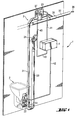
- In Fig. 1 a part of a vacuum sewer system is generally indicated by
reference numeral 1. Thevacuum sewer system 1 comprises a source ofsewage 2, in this embodiment a toilet unit (shown by broken lines). The source of sewage may also for example be a urinal, wash basin, shower unit, condensate receptacle, or the like. The vacuum sewer system further comprises sewer piping, generally indicated byreference numeral 3, and comprising afirst sewer pipe 31, or so-called riser or branch pipe, asecond sewer pipe 32, or so-called main line, and athird sewer pipe 33. Thefirst sewer pipe 31 is connected to thethird sewer pipe 33 by afirst pipe junction 34 and to thesecond sewer pipe 32 by asecond pipe junction 35. - The source of sewage is provided with a
first sewer valve 21, anoutlet port 22 of which is connected to thefirst pipe junction 34. Alternatively theoutlet port 22 may be connected directly to the first sewer pipe or the third sewer pipe, directly or through a pipe junction. Thefirst sewer pipe 31 is connected to thesecond sewer pipe 32 through asecond sewer valve 23. Furthermore, thethird sewer pipe 33, at an end opposite thefirst pipe junction 34 end (i.e. opposite thefirst sewer valve 21 end) of thethird sewer pipe 33, is provided with a third valve means 24, particularly an aeration valve. - The
vacuum sewer system 1 is provided with vacuum from a vacuum generation means, only generally indicated in the drawing by anarrow 36 in connection with thesecond sewer pipe 32. A constant vacuum connection is provided between thesecond sewer pipe 32 and thefirst sewer pipe 31 over thesecond sewer valve 23 through a pressure equalisation means 37, in this embodiment aconnection tube 37 connected to the second and first sewer pipes at opposite sides of the second sewer valve respectively. This arrangement also reduces the noise level at the pressure equalisation stage, i.e. when the vacuum level is reinstated in the system, subsequent the drainage or flushing function. - The vacuum sewer system is also provided with a
control center 4 which is in fluid communication with the vacuum generated by the vacuum generation means 36 through tubing, particularly afirst tube 41 connected to the connection tube (pressure equalisation means) 37. The connection could as well be made to any other point of the vacuum sewer system providing vacuum in an appropriate manner. - Further the
control center 4 is in fluid communication with thefirst sewer valve 21, thesecond sewer valve 23 and the third valve means 24, which in this embodiment are vacuum activated valves, in order to control the opening and closing of said valves. The fluid communication is established by further tubing, particularly asecond tube 42, athird tube 43 and a fourth tube 44 (via the third tube 43) respectively. - In the following the operation of the vacuum sewer system will be described in relation to the components given above.
- Vacuum is provided in the
sewer piping 3 by way of the vacuum generating means 36, whereby vacuum is maintained in thesecond sewer pipe 32 and in the first andthird sewer pipes second sewer pipe 32 and thefirst sewer pipe 31, regardless of the state or position of thesecond sewer valve 23. - At an initial stage the first and
second sewer valves toilet unit 2 is to be drained, a flush function is activated through thecontrol center 4 in a manner known per se. Thecontrol center 4 activates the vacuum connection through thefirst tube 41 and conveys the vacuum effect forward through thesecond tube 42 to thefirst sewer valve 21 in order to open the same. Due to the substantially normal atmospheric pressure prevailing in thetoilet unit 2 bowl, the sewage is drained or flushed through thefirst sewer valve 21 in the form of discrete slugs into the first andthird sewer pipe sewer pipes first sewer valve 21 is about 0 kPa (0 bar) and thefirst sewer valve 21 is closed. At this first transport phase the first andthird sewer pipes - Subsequently, after a predetermined time, for example about 1 to 2 seconds, the
control center 4 activates the vacuum connection through thefirst tube 41 and conveys the vacuum effect forward through thethird tube 43 and thefourth tube 44 to thesecond sewer valve 23 and to theaeration valve 24 respectively, whereby said valves are opened. This results in that the sewage is subjected to a second transport phase, during which it is transported forward from the first andthird sewer pipes second sewer pipe 32 through thesecond sewer valve 23 due to the suction effect of the vacuum prevailing in thesecond sewer pipe 32. The function of theaeration valve 24 at the distal end of thethird sewer pipe 33 is to provide additional atmospheric transport air into the third andfirst sewer pipes - After the second transport phase the
second sewer valve 23 and theaeration valve 24 are closed and the desired vacuum level is reinstated in thevacuum piping 3 by way of the vacuum generation means 36, whereby the system is ready for a next drainage or flushing function. - The
control center 4 is advantageously provided for example with solenoid valves for monitoring the connection and conveyance of vacuum through the appropriate tubes described above. Such solenoid valves are advantageously three-way valves, whereby in order to open the first sewer valve and correspondingly the second sewer valve and the aeration valve (third valve means), vacuum is allowed to communicate through a first and second port of the corresponding control center (solenoid) valve, and subsequently, in order to close said valves, firstly the vacuum communication is shut of and secondly a third port of the corresponding control center (solenoid) valve is opened to allow surrounding atmospheric air to communicate through thecorresponding tubing - In order to reduce the noise level in connection with the drainage or flushing function and the subsequent pressure equalisation stage, it has shown to be advantageous to provide a pipe section with an enlarged pipe diameter more or less directly after the
outlet port 22 of thefirst sewer valve 21. This can be done by giving the first pipe junction 34 a larger diameter than thefirst sewer pipe 31 and thethird sewer pipe 33. The diameter of the third sewer pipe can also be larger than the diameter of the first sewer pipe in order to provide for a larger volume intermediate receptacle, if so desired. - A desired volume of the intermediate receptacle for the sewage, i.e. the first and third sewer pipes, can easily be provided by changing the lenghts, and naturally also the diameters, of said sewer pipes as described above. Different volumes may be applicable depending on in which connection the vacuum sewer system is used. Typical diameters involved in vacuum sewer systems are e.g. about 50 mm for the branch or first sewer pipe, whereby the enlarged diameter discussed above preferably could be about 63 mm.
- The use of the aeration valve and the third sewer pipe can also be dependent of the type of sewage in question. If the source of sewage e.g. is a urinal or a wash basin, the sewage is "lighter", whereby additional transport air and additional volume of the intermediate receptacle may not be necessary. If the source of sewage e.g. is a toilet unit, the sewage in question may be "heavier", whereby the extra transport air and the additional volume may be advantageous.
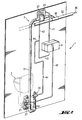
- The second embodiment shown in Fig. 2 substantially corresponds to the embodiment shown in Fig. 1, and consequently the same reference numerals have been used for the same components.
- The basic difference, however, is that the source of
sewage 2 in this embodiment is shown as a urinal, i.e. providing a "lighter" form of sewage. Theoutlet port 22 of thefirst sewer valve 21 is connected to thefirst pipe junction 34, which has been provided with a larger diameter than said outlet port, and thefirst sewer pipe 31 is connected to a first end of thefirst pipe junction 34 and the third valve means 24, i.e. the aeration valve, directly to a second end of thefirst pipe junction 34. - The operation of this embodiment corresponds to the operation of the first embodiment, with the exception of the arrangements in relation to the third sewer pipe.
- The first sewer valve, the second sewer valve and the aeration valve have above been described as pneumatic, vacuum activated valves. However, one or more of the valves may as well be designed as mechanically or electrically operated valves, if so is preferred. Consequently, the control center can be adapted accordingly.
- The drawings and the description related thereto are only intended for clarification of the idea of the invention. The invention may vary in further detail, e.g. relating to the enlarged outlet of the source of sewage, the volume of the intermediate receptacle, the provision of additional transport air, etc., within the scope of the ensuing claims.
Claims (13)
- Vacuum sewer system comprising a source of sewage (2), sewer piping (3) comprising a first sewer pipe (31) and a second sewer pipe (32), a first sewer valve (21) with an outlet port (22) arranged between the source of sewage and the first sewer pipe, a second sewer valve (23) arranged between the first sewer pipe and the second sewer pipe, and a vacuum generating means (36) for providing vacuum in the sewer piping, characterised in that the first sewer pipe (31) provides an intermediate receptacle for the sewage.
- Vacuum sewer system according to claim 1, characterised in that the first sewer pipe (31) is provided with a third valve means (24) at the first sewer valve (21) end of the first sewer pipe.
- Vacuum sewer system according to claim 1 or 2, characterised in that a pipe section (34) with a larger diameter than the outlet port (22) of the first sewer valve (21) is arranged downstream of the first sewer valve.
- Vacuum sewer system according to claim 3, characterised in that the pipe section with a larger diameter comprises a first pipe junction (34) that is arranged between the outlet port (22) of the first sewer valve (21) and the first sewer pipe (31).
- Vacuum sewer system according to claim 4, characterised in that the first pipe junction (34) is provided with a third valve means (24).
- Vacuum sewer system according to claim 1, characterised in that the system comprises a third sewer pipe (33) in fluid communication with the first sewer pipe (31) at the first sewer valve (21) end of the first sewer pipe.
- Vacuum sewer system according to claim 6, characterised in that the third sewer pipe (33) is connected to the first pipe junction (34).
- Vacuum sewer system according to claim 6, characterised in that the third sewer pipe (33) is provided with a third valve means (24) at an end opposite the first sewer valve (21) end of the third sewer pipe.
- Vacuum sewer system according to any of the preceding claims, characterised in that the system is provided with a pressure equalisation means (37) connecting the first sewer pipe (31) and the second sewer pipe (32) at opposite sides of the second sewer valve (23) respectively.
- Vacuum sewer system according to any of the preceding claims, characterised in that the system is provided with a control center (4) comprising control of the first sewer valve (21), the second sewer valve (23) and the third valve means (24).
- Vacuum sewer system according to claim 10, characterised in that first sewer valve (21), the second sewer valve (23) and/or the third valve means (24) are vacuum activated valves, and in that the control center (4) is in fluid communication with the vacuum generated by the vacuum generation means (36) and the first sewer valve (21), the second sewer valve (23) and/or the third valve means (24).
- Vacuum sewer system according to claim 11, characterised in that the control center (4) is in fluid communication with the vacuum generated by the vacuum generation means (36) through the pressure equalisation means (37).
- Vacuum sewer system according to claim 11 or 12, characterised in that the fluid communication between the control center (4) and the vacuum generated by the vacuum generation means (36) and the first sewer valve (21), second sewer valve (23) and/or the third valve means (24) is provided by tubing (41,42,43,44).
Applications Claiming Priority (2)
| Application Number | Priority Date | Filing Date | Title |
|---|---|---|---|
| FI20011260A FI110444B (en) | 2001-06-14 | 2001-06-14 | The vacuum sewer system |
| FI20011260 | 2001-06-14 |
Publications (2)
| Publication Number | Publication Date |
|---|---|
| EP1267006A2 true EP1267006A2 (en) | 2002-12-18 |
| EP1267006A3 EP1267006A3 (en) | 2004-02-11 |
Family
ID=8561408
Family Applications (1)
| Application Number | Title | Priority Date | Filing Date |
|---|---|---|---|
| EP20020006020 Withdrawn EP1267006A3 (en) | 2001-06-14 | 2002-03-15 | Vacuum sewer system |
Country Status (13)
| Country | Link |
|---|---|
| US (1) | US6648002B2 (en) |
| EP (1) | EP1267006A3 (en) |
| JP (1) | JP2003034964A (en) |
| KR (1) | KR20020095427A (en) |
| CN (1) | CN1392313A (en) |
| AU (1) | AU2756902A (en) |
| BR (1) | BR0201759A (en) |
| CA (1) | CA2381002A1 (en) |
| CZ (1) | CZ20022053A3 (en) |
| FI (1) | FI110444B (en) |
| HU (1) | HUP0201059A2 (en) |
| PL (1) | PL353051A1 (en) |
| RU (1) | RU2002116030A (en) |
Families Citing this family (16)
| Publication number | Priority date | Publication date | Assignee | Title |
|---|---|---|---|---|
| DE102006016030B4 (en) * | 2006-04-05 | 2011-01-20 | Airbus Operations Gmbh | System for flushing a vacuum urinal |
| US8397318B2 (en) * | 2006-04-05 | 2013-03-19 | Airbus Operations Gmbh | Flushing system for a vacuum toilet |
| FI120414B (en) * | 2006-07-03 | 2009-10-15 | Evac Int Oy | Installation unit for sanitary space |
| CN101583766A (en) * | 2006-10-24 | 2009-11-18 | 欧沃德·阿巴迪 | Toilet flushing system and method without using a toilet tank |
| DE102007061255A1 (en) * | 2007-12-19 | 2009-07-02 | Airbus Deutschland Gmbh | System for flushing a vacuum toilet |
| US8607370B2 (en) * | 2008-10-03 | 2013-12-17 | B/E Aerospace, Inc. | Flush valve and vacuum generator for vacuum waste system |
| US8051873B2 (en) * | 2008-11-18 | 2011-11-08 | G.A. Fleet Associates, Inc. | Wet well pumping system and method of installing and servicing the system |
| DE102010000609B4 (en) * | 2010-03-02 | 2015-03-12 | Roediger Vacuum Gmbh | control arrangement |
| WO2013025888A1 (en) | 2011-08-16 | 2013-02-21 | Flow Control Llc. | Toilet with ball valve mechanism and secondary aerobic chamber |
| US10041241B2 (en) | 2015-03-30 | 2018-08-07 | B/E Aerospace, Inc. | Method and apparatus for installation of a toilet system on an aircraft |
| EP3408462B1 (en) * | 2016-01-26 | 2019-11-27 | Evac Oy | Method for controlling a vacuum sewage system for a building or for a marine vessel |
| RU2728865C2 (en) * | 2016-02-16 | 2020-07-31 | Евак Ой | Toilet device |
| US9926693B2 (en) * | 2016-06-20 | 2018-03-27 | Larry McCall | Water-saving accessory for a toilet, basin thereof, and toilet with water-saving feature |
| CN108824565B (en) * | 2018-07-25 | 2024-02-13 | 厚力德机器(杭州)有限公司 | Full-mechanical micro-control air valve damping vacuum interface collecting device |
| WO2020034704A1 (en) * | 2018-08-15 | 2020-02-20 | 王圳 | Gas cylinder shell type vacuum pollution discharge apparatus |
| CN108951811B (en) * | 2018-08-15 | 2021-02-09 | 北京土川科技有限责任公司 | Gas cylinder shell type vacuum pollution discharge device |
Citations (4)
| Publication number | Priority date | Publication date | Assignee | Title |
|---|---|---|---|---|
| DE643583C (en) * | 1933-09-19 | 1937-04-12 | Henri Lancery | Sewer system for the removal of household and industrial waste by means of negative pressure |
| US5396668A (en) * | 1991-04-23 | 1995-03-14 | Sanivac Vakuumtechnik Gmbh | System for discharging wastes |
| DE19800958A1 (en) * | 1997-02-12 | 1998-08-13 | Sanivac Vakuumtechnik Gmbh | Suction extraction device for sewage tanks |
| EP1013838A1 (en) * | 1998-12-23 | 2000-06-28 | Evac International Oy | Waste transport arrangement |
Family Cites Families (2)
| Publication number | Priority date | Publication date | Assignee | Title |
|---|---|---|---|---|
| US4713847B1 (en) * | 1987-02-02 | 1996-05-28 | Waertsilae Oy Ab | Vacuum toilet system |
| FI77082C (en) * | 1987-04-06 | 1989-01-10 | Waertsilae Oy Ab | Vacuum Drainage Device |
-
2001
- 2001-06-14 FI FI20011260A patent/FI110444B/en active
-
2002
- 2002-03-15 EP EP20020006020 patent/EP1267006A3/en not_active Withdrawn
- 2002-03-21 AU AU27569/02A patent/AU2756902A/en not_active Abandoned
- 2002-03-22 HU HU0201059A patent/HUP0201059A2/en unknown
- 2002-03-25 US US10/105,552 patent/US6648002B2/en not_active Expired - Fee Related
- 2002-03-27 PL PL35305102A patent/PL353051A1/en not_active Application Discontinuation
- 2002-04-09 CA CA 2381002 patent/CA2381002A1/en not_active Abandoned
- 2002-05-06 BR BR0201759A patent/BR0201759A/en not_active Application Discontinuation
- 2002-05-07 KR KR1020020024916A patent/KR20020095427A/en not_active Application Discontinuation
- 2002-05-14 JP JP2002138077A patent/JP2003034964A/en active Pending
- 2002-06-12 CZ CZ20022053A patent/CZ20022053A3/en unknown
- 2002-06-13 RU RU2002116030/03A patent/RU2002116030A/en not_active Application Discontinuation
- 2002-06-14 CN CN02123273A patent/CN1392313A/en active Pending
Patent Citations (4)
| Publication number | Priority date | Publication date | Assignee | Title |
|---|---|---|---|---|
| DE643583C (en) * | 1933-09-19 | 1937-04-12 | Henri Lancery | Sewer system for the removal of household and industrial waste by means of negative pressure |
| US5396668A (en) * | 1991-04-23 | 1995-03-14 | Sanivac Vakuumtechnik Gmbh | System for discharging wastes |
| DE19800958A1 (en) * | 1997-02-12 | 1998-08-13 | Sanivac Vakuumtechnik Gmbh | Suction extraction device for sewage tanks |
| EP1013838A1 (en) * | 1998-12-23 | 2000-06-28 | Evac International Oy | Waste transport arrangement |
Also Published As
| Publication number | Publication date |
|---|---|
| CA2381002A1 (en) | 2002-12-14 |
| CZ20022053A3 (en) | 2003-01-15 |
| FI20011260A0 (en) | 2001-06-14 |
| BR0201759A (en) | 2003-03-11 |
| US6648002B2 (en) | 2003-11-18 |
| JP2003034964A (en) | 2003-02-07 |
| US20020189669A1 (en) | 2002-12-19 |
| PL353051A1 (en) | 2002-12-16 |
| FI110444B (en) | 2003-01-31 |
| CN1392313A (en) | 2003-01-22 |
| HU0201059D0 (en) | 2002-05-29 |
| HUP0201059A2 (en) | 2004-04-28 |
| KR20020095427A (en) | 2002-12-26 |
| AU2756902A (en) | 2002-12-19 |
| RU2002116030A (en) | 2004-01-10 |
| EP1267006A3 (en) | 2004-02-11 |
Similar Documents
| Publication | Publication Date | Title |
|---|---|---|
| US6648002B2 (en) | Vacuum sewer system | |
| EP1013838B1 (en) | Waste transport arrangement | |
| US8381324B2 (en) | Vacuum sewage system | |
| US11391031B2 (en) | Method of controlling a vacuum waste system and a vacuum waste system | |
| US8621677B2 (en) | Odour seal for a vacuum toilet drain system | |
| ATE278847T1 (en) | NEUTRAL PRESSURE SEWAGE SYSTEM | |
| US7207073B1 (en) | Vacuum assisted toilet | |
| KR20000011409A (en) | Sewer system | |
| US20020000246A1 (en) | Suction-type siphon for a flushing device | |
| WO2003004785A1 (en) | Vacuum sewer system | |
| EP1255065A1 (en) | Valve | |
| JPH0438336A (en) | Vacuum sewage water mechanism and operating method thereof | |
| EP1449968A3 (en) | Water cistern for a closet and corresponding closet | |
| US6283140B1 (en) | Waste fluid discharge column | |
| FI77911B (en) | FOERFARANDE FOER STOETVIS TRANSPORT AV VAETSKA. | |
| JP4412845B2 (en) | Vacuum sewer system | |
| FI128742B (en) | A cleaning arrangement and method for cleaning a vacuum toilet system | |
| GB2281750A (en) | Overflow fitting for a siphon-discharge W.C. cistern | |
| JPH08113973A (en) | Vacuum type sanitary sewage collection device | |
| JPH05156693A (en) | Laying of vacuum sewerage |
Legal Events
| Date | Code | Title | Description |
|---|---|---|---|
| PUAI | Public reference made under article 153(3) epc to a published international application that has entered the european phase |
Free format text: ORIGINAL CODE: 0009012 |
|
| AK | Designated contracting states |
Kind code of ref document: A2 Designated state(s): AT BE CH CY DE DK ES FI FR GB GR IE IT LI LU MC NL PT SE TR |
|
| AX | Request for extension of the european patent |
Free format text: AL;LT;LV;MK;RO;SI |
|
| PUAL | Search report despatched |
Free format text: ORIGINAL CODE: 0009013 |
|
| AK | Designated contracting states |
Kind code of ref document: A3 Designated state(s): AT BE CH CY DE DK ES FI FR GB GR IE IT LI LU MC NL PT SE TR |
|
| AX | Request for extension of the european patent |
Extension state: AL LT LV MK RO SI |
|
| 17P | Request for examination filed |
Effective date: 20040624 |
|
| AKX | Designation fees paid |
Designated state(s): AT BE CH CY DE DK ES FI FR GB GR IE IT LI LU MC NL PT SE TR |
|
| STAA | Information on the status of an ep patent application or granted ep patent |
Free format text: STATUS: THE APPLICATION HAS BEEN WITHDRAWN |
|
| 18W | Application withdrawn |
Effective date: 20050503 |