EP1274203A1 - Method for setting user equipment identifier in radio communication system - Google Patents
Method for setting user equipment identifier in radio communication system Download PDFInfo
- Publication number
- EP1274203A1 EP1274203A1 EP02014799A EP02014799A EP1274203A1 EP 1274203 A1 EP1274203 A1 EP 1274203A1 EP 02014799 A EP02014799 A EP 02014799A EP 02014799 A EP02014799 A EP 02014799A EP 1274203 A1 EP1274203 A1 EP 1274203A1
- Authority
- EP
- European Patent Office
- Prior art keywords
- user equipment
- layer
- equipment identifier
- mac
- indicator
- Prior art date
- Legal status (The legal status is an assumption and is not a legal conclusion. Google has not performed a legal analysis and makes no representation as to the accuracy of the status listed.)
- Granted
Links
Images


Classifications
-
- H—ELECTRICITY
- H04—ELECTRIC COMMUNICATION TECHNIQUE
- H04W—WIRELESS COMMUNICATION NETWORKS
- H04W8/00—Network data management
- H04W8/22—Processing or transfer of terminal data, e.g. status or physical capabilities
-
- H—ELECTRICITY
- H04—ELECTRIC COMMUNICATION TECHNIQUE
- H04W—WIRELESS COMMUNICATION NETWORKS
- H04W8/00—Network data management
- H04W8/26—Network addressing or numbering for mobility support
-
- H—ELECTRICITY
- H04—ELECTRIC COMMUNICATION TECHNIQUE
- H04L—TRANSMISSION OF DIGITAL INFORMATION, e.g. TELEGRAPHIC COMMUNICATION
- H04L61/00—Network arrangements, protocols or services for addressing or naming
-
- H—ELECTRICITY
- H04—ELECTRIC COMMUNICATION TECHNIQUE
- H04L—TRANSMISSION OF DIGITAL INFORMATION, e.g. TELEGRAPHIC COMMUNICATION
- H04L61/00—Network arrangements, protocols or services for addressing or naming
- H04L61/50—Address allocation
-
- H—ELECTRICITY
- H04—ELECTRIC COMMUNICATION TECHNIQUE
- H04L—TRANSMISSION OF DIGITAL INFORMATION, e.g. TELEGRAPHIC COMMUNICATION
- H04L69/00—Network arrangements, protocols or services independent of the application payload and not provided for in the other groups of this subclass
- H04L69/30—Definitions, standards or architectural aspects of layered protocol stacks
- H04L69/32—Architecture of open systems interconnection [OSI] 7-layer type protocol stacks, e.g. the interfaces between the data link level and the physical level
- H04L69/322—Intralayer communication protocols among peer entities or protocol data unit [PDU] definitions
- H04L69/324—Intralayer communication protocols among peer entities or protocol data unit [PDU] definitions in the data link layer [OSI layer 2], e.g. HDLC
-
- H—ELECTRICITY
- H04—ELECTRIC COMMUNICATION TECHNIQUE
- H04L—TRANSMISSION OF DIGITAL INFORMATION, e.g. TELEGRAPHIC COMMUNICATION
- H04L9/00—Cryptographic mechanisms or cryptographic arrangements for secret or secure communications; Network security protocols
- H04L9/40—Network security protocols
-
- H—ELECTRICITY
- H04—ELECTRIC COMMUNICATION TECHNIQUE
- H04W—WIRELESS COMMUNICATION NETWORKS
- H04W8/00—Network data management
- H04W8/22—Processing or transfer of terminal data, e.g. status or physical capabilities
- H04W8/24—Transfer of terminal data
-
- H—ELECTRICITY
- H04—ELECTRIC COMMUNICATION TECHNIQUE
- H04L—TRANSMISSION OF DIGITAL INFORMATION, e.g. TELEGRAPHIC COMMUNICATION
- H04L2101/00—Indexing scheme associated with group H04L61/00
- H04L2101/60—Types of network addresses
- H04L2101/618—Details of network addresses
- H04L2101/622—Layer-2 addresses, e.g. medium access control [MAC] addresses
-
- H—ELECTRICITY
- H04—ELECTRIC COMMUNICATION TECHNIQUE
- H04L—TRANSMISSION OF DIGITAL INFORMATION, e.g. TELEGRAPHIC COMMUNICATION
- H04L61/00—Network arrangements, protocols or services for addressing or naming
- H04L61/50—Address allocation
- H04L61/5038—Address allocation for local use, e.g. in LAN or USB networks, or in a controller area network [CAN]
-
- H—ELECTRICITY
- H04—ELECTRIC COMMUNICATION TECHNIQUE
- H04W—WIRELESS COMMUNICATION NETWORKS
- H04W4/00—Services specially adapted for wireless communication networks; Facilities therefor
- H04W4/12—Messaging; Mailboxes; Announcements
-
- H—ELECTRICITY
- H04—ELECTRIC COMMUNICATION TECHNIQUE
- H04W—WIRELESS COMMUNICATION NETWORKS
- H04W8/00—Network data management
-
- H—ELECTRICITY
- H04—ELECTRIC COMMUNICATION TECHNIQUE
- H04W—WIRELESS COMMUNICATION NETWORKS
- H04W80/00—Wireless network protocols or protocol adaptations to wireless operation
- H04W80/02—Data link layer protocols
-
- H—ELECTRICITY
- H04—ELECTRIC COMMUNICATION TECHNIQUE
- H04W—WIRELESS COMMUNICATION NETWORKS
- H04W88/00—Devices specially adapted for wireless communication networks, e.g. terminals, base stations or access point devices
- H04W88/02—Terminal devices
Definitions
- the present invention relates to a method for setting a terminal(user equipment) identifier in a mobile communication system as terminal (user equipment) identification information, when data delivered through a dedicated logical channel is transmitted through a common transport channel. More specifically, it relates to a method for setting a user equipment identifier in a UMTS (Universal Mobile Telecommunications System, European type IMT-2000 radio communication system).
- UMTS Universal Mobile Telecommunications System, European type IMT-2000 radio communication system
- RLC SDU Radio Link Control Service Data Unit
- message type indicator which serve the purpose of user equipment identification information
- RRC Radio Resources Control
- RLC Radio Link Control
- the RLC layer sets a user equipment identifier indicator according to the transmitted message type indicator and transmits it with the data to a MAC (Medium Access Control) layer.
- the MAC layer adds the appropriate user equipment identification information to the data received.
- 3GPP Third Generation Partnership Project
- TSGs Technical Specification Groups
- RAN Radio Access Network
- UMTS Universal Mobile Telecommunications System, European type IMT-2000 System
- UTRAN Terrestrial Radio Access Network
- a TSG-RAN group consists of one plenary group and four working groups.
- WG1 (working group 1) has been developing specifications for a physical layer (first layer), and WG2 has been specifying functions of a data link layer (second layer) and a network layer (third layer).
- WG3 has been developing specifications for interfaces among base stations, RNCs (Radio Network Controller) and core networks in the UTRAN.
- WG4 has been discussing requirements for radio link performance and radio resource management.
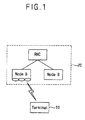
- Figure 1 illustrates a structure of the UTRAN.
- the UTRAN 20 includes a Node B and an RNC.
- Node B is controlled by the RNC, and works as an access point by receiving uplink information from the user equipment 10 and by transmitting downlink information from the UTRAN through the physical layer linking.
- the RNC performs allocation and management of radio resources.
- the RNC can be classified as either control or serving RNC.
- the control RNC directly manages Node B and manages common radio resources.
- the serving RNC manages dedicated radio resources allocated to each user equipment.
- the control RNC and the serving RNC can be the same. However, when a user equipment moves from a serving RNC's region to other RNC's regions, a control RNC and a serving RNC can be different.
- control RNC and the serving RNC are different, data to be transmitted to a user equipment is transmitted to a control RNC after passing through a serving RNC and transmitted to a user equipment through a Node B connected to the control RNC.
- a Radio Network Sub-system includes one RNC and several Node Bs.
- RNS Radio Network Sub-system
- the RNS where a serving RNC is located is referred to as serving RNS.
- Figure 2 illustrates a structure of a general radio interface protocol according to a radio access network specification of the 3GPP.
- a radio interface protocol between a user equipment and the UTRAN is horizontally divided into a physical layer (first layer), a data link layer (second layer) and a network layer (third layer). It is also vertically divided into a control plane for control signaling and a user plane for data information transfer.
- the control plane contains a radio resource control (“RRC”) layer, a radio link control (“RLC”) layer, a medium access control (“MAC”) layer and a physical layer as the first layer
- the user plane contains a packet data convergence protocol (“PDCP”) layer, a broadcast/multicast control (“BMC”) layer, an RLC layer, a MAC layer and a physical layer.
- RRC radio resource control
- RLC radio link control
- MAC medium access control
- the user plane contains a packet data convergence protocol (“PDCP”) layer, a broadcast/multicast control (“BMC”) layer, an RLC layer, a MAC layer and a physical layer.
- PDCP packet data convergence protocol
- BMC broadcast/multicast control
- the physical layer provides information transfer service to an upper layer by using various radio transfer techniques. It is connected to the MAC layer as an upper layer through transport channels.. The data between the MAC layer and the physical layer are transmitted through the transport channels.
- the transport channels are classified as a DTCH (Dedicated Transport Channel) and a CTCH (Common Transport Channel).
- the DTCH is a transport channel exclusively used by one user equipment
- the CTCH is a transport channel jointly used by several user equipment.
- the MAC layer provides a reallocation service of a MAC parameter for allocating and reallocating radio resources. It is connected to the RLC layer through a logical channel, and various logical channels are provided according to the type of information transmitted in general, a control channel is used when transmitting information on the control plane, and a traffic channel is used when transmitting information on the user plane.
- the RLC layer provides the function of setting and releasing radio links. In addition, it performs segmenting and reassembling functions of an RLC Service Data Unit ("SDU") delivered from an upper layer on the user plane.
- SDU RLC Service Data Unit
- the size of the RLC SDU is adjusted on the RLC layer to be suitable for a processing capacity. Afterwards, header information is added, and it is transmitted to the MAC layer as an RLC Protocol Data Unit (“PDU”) format.
- PDU RLC Protocol Data Unit
- the PDCP layer Since the PDCP layer is an upper layer of the RLC layer, it converts the data of packet network protocols, such as IPv4 or IPv6, into the data of a format suitable for the RLC layer, and vice versa. In addition, it assists the lower layers to transfer data through the radio interface efficiently by reducing unnecessary control information used in a wire network. That function is referred to as header compression, and, for example, the header compression can be used to reduce TCP/IP header information.
- the BMC layer exists on the user plane, and it is used for applying a broadcast service or a multicast service to the system having a radio interface.
- the RRC provides information broadcast services to all user equipment located within a certain area.
- it performs a control plane signal processing for a control signal exchanging between the third layers of transmitting and receiving side and has functions for setting/maintaining/releasing radio resources between user equipment and the UTRAN.
- the RRC has functions for setting/maintaining/releasing a Radio Bearer and allocating/reconfiguring /releasing radio resources required for radio access networking.
- the Radio Bearer means a service provided by the second layer for data transfer between the user equipment and the UTRAN. That is, setting a radio bearer means specifying the characteristics of a protocol layer and a channel required to provide a certain services, and setting specific parameters and operation method.
- Each user equipment also includes all radio interface layers
- protocol layers are dispersed in several constituent elements of a UTRAN (UMTS Terrestrial Radio Access Network).
- Figure 3 illustrates an example of a protocol layer hierarchy corresponding to the constituent elements of a Radio Access Network.
- the RLC layer is placed in the serving RNC.
- the functions of the MAC layer can be divided according to the type of a transport channel and can be placed either in the serving RNC or in the control RNC.
- the MAC layer is divided into a MAC-d sub layer and a MAC-c/sh sub layer according to the type of transport channel. These are respectively placed in the serving RNC and the control RNC.
- a MAC-c/sh sub layer and a MAC-d sub layer are placed on the same RNC.
- the MAC-d sub layer manages a dedicated logical channel, which is dedicated to a user equipment
- the MAC-c/sh sub layer manages a common transport channel.
- the MAC-c/sh sub layer manages the common transport channel, which is jointly used by all user equipment within the cell, each cell has one MAC-c/sh sub layer.
- the MAC-d sub layer provides a dedicated service to a user equipment, and one MAC-d sub layer exists for each one user equipment.
- the physical layer (PHY) is placed in the Node B.
- Figure 4 illustrates a structure of an RLC layer and a MAC layer in the UTRAN.
- the RLC layer stores an RLC PDU in an RLC buffer and transmits a certain number of PDUs corresponding to a request from the MAC layer.
- the RLC PDU received in the MAC-d layer is transmitted through Dedicated Transport Channel (DTCH) or Common Transport Channel (CTCH) by channel switching.
- DTCH Dedicated Transport Channel
- CCH Common Transport Channel
- DCH Dedicated Channel
- the RLC PDU is transmitted through the CTCH, it is transmitted from the MAC-d sub layer to the MAC-c/sh sub layer, and a related header is added on. Thereafter, it is multiplexed through other logical channels and is transmitted through the common transport channel such as PCH (Paging Channel), FACH (Forward Access Channel) and DSCH (Downlink Shared Channel) etc.
- PCH Paging Channel
- FACH Forward Access Channel
- DSCH Downlink Shared Channel
- DCH Dedicated Channel
- CCH common transport channel
- RACH Reverse Access Channel
- CPCH Common Packet Channel
- the data is transmitted to the RLC layer via the path converse in the down_link.
- the structures of the RLC layer and the MAC layer in the user equipment are almost the same as the structure in Figure 4.
- FACH Forward Access Channel
- the RLC PDU transmitted from the RLC layer uses the FACH of the MAC-c/sh sub layer, it is transmitted to the MAC-c/sh sub layer through channel switching and control transmission multiplexing.
- the control transmission multiplexing means multiplexing several logical channels.
- Data transmitted to the MAC-c/sh sub layer is multiplexed with data of other logical channels
- a destination user equipment's identifier is added to the MAC PDU through a user equipment identifier inserting for data multiplexing.
- a TCTF (Target Channel Type Field) mapping for data multiplexing maps the relationship between the logical channel and the transport channel.
- the RLC PDU delivered from the RLC layer of the UTRAN or the user equipment to the MAC layer through the logical channel is transmitted to the physical layer through an appropriate transport channel.
- the data passed the dedicated logical channel is transmitted through the common transport channel as described above, it passes through the MAC-d sub layer and the MAC-c/sh sub layer and ultimately transmitted to the physical layer
- MAC PDU header information which is added by each part of the MAC layer, can include a TCTF field, a user equipment identifier type field, a user equipment identifier field and a C/T field etc.
- the TCTF field indicates the following: the type of a logical channel the data of which is transmitted through a specific transport channel; the user equipment identifier type field indicating which user equipment identifier among various types of user equipment identifiers is used; the user equipment identifier field including identification information of a user equipment designated in the user equipment identifier type field; and the C/T field which provides information for distinguishing each logical channel when data of several logical channels are transmitted to one transport channel.
- a user equipment identifier used for identifying a user equipment on the MAC-c/sh sub layer shown in Figure 4, can be divided into two types according to a user equiprnent's distinguishable geographical region (i.e a range in which each user equipment can cover) in a network.
- a C-RNTI Cell Radio Network Temporary Identity
- the C-RNTI has unique value only in a pertinent cell, and a cell region is the effective region of the C-RNTI. Therefore, when the user equipment moves to another cell, the C-RNTI has to be changed.
- a U-RNTI (UTRAN Radio Network Temporary Identify) is used for identifying a certain user equipment in the UTRAN, and it is composed of a S-RNTI (SRNC RNTI) and a serving RNC identifier.
- the S-RNTI is an identification value used for identifying a certain user equipment in the serving RNC, and each user equipment has a unique S-RNTI value in the serving RNC.
- the serving RNC identifier is used to identify the RNC in the UTRAN. Accordingly, in order to designate a certain user equipment in the UTRAN, serving RNC identifier information and an identification value of the user equipment in the pertinent RNC are required.
- the U-RNTI is a unique value in the UTRAN and is not changed even in cases where the use equipment is moved to a different cell in a RNC.
- a new U-RNTI value has to be allocated.
- a U-RNTI effective range is a region managed by a serving RNC.
- a user equipment is identified by using only one of the two types of user equipment identifier: with the C-RNTI, a 16 bit is required, and with the U-RNTI, a 32 bit is required. Accordingly, by using C-RNTI the limited radio channel resources can be efficiently used. In some cases, a value of the U-RNTI is used. For example, when a C-RNTI value is changed frequently, a user equipment can be identified effectively by using a U-RNTI value.
- identification information of a user equipment is added to a MAC PDU by the MAC layer of the transmitter side , and the identification information of the user equipment is identified in the receiver side of the MAC layer.
- the transmitter side MAC layer performs multiplexing of an RLC PDU transmitted from the RLC layer and adding identification information of a user equipment to a MAC PDU(a data unit corresponding to the RLC PDU), the MAC layer is unable to recognize when and which type of user equipment identifier is used, and can not change the type of user equipment identifier dynamically
- a method for determining information required for setting a user equipment identifier (C-RNT, U-RNTI) from other layers to a MAC (Medium Access Control) layer and a method for setting a user equipment identifier value are explained below.
- the steps in setting a user equipment identifier with the present invention are as follows: 1) transmitting data and a message type indicator as user equipment identification information from a RRC (Radio Resources Control) layer to an RLC (Radio Link Control) layer; 2) setting a user equipment identifier indicator according to the received message type indicator in the RLC layer and transmitting it with the data to a MAC (Medium Access Control) layer; 3) selecting a user equipment identifier type and a user equipment identifier according to the set user equipment indication identifier, adding it to a header of a MAC PDU (Medium Access Control Protocol Data Unit) in the MAC layer; and 4) transmitting it to a reception side MAC layer.
- a MAC PDU is composed of a header and a MAC SDU.
- MAC SDU is substantially the same as RLC PDU.
- the method further includes: performing a radio transmission in the MAC layer as a MAC PDU (Medium Access Control Protocol Data Unit) format; adding a user equipment identifier type field indicating a user equipment identifier field and the type of a user equipment identifier to the MAC PDU header; and transmitting it to the reception side and distinguishing a user equipment by using the MAC PDU header information in the reception side
- MAC PDU Medium Access Control Protocol Data Unit
- the RLC layer receives data (RLC SDU) and a message type indicator as user equipment identification information from the RRC layer and sets a user equipment identifier indicator for distinguishing a user equipment appropriate to a network region managing the user equipment in a mobile communication system.
- the MAC layer receives the user equipment identifier indicator designating the type (U-RNTI, C-RNTI) of user equipment identifier, and the MAC layer sets user equipment identifier and a user equipment identifier type field as MAC PDU header information.
- the type of a user equipment identifier is determined when setting the radio bearer, and the set user equipment identifier indicator is transmitted from the RLC layer to the MAC layer in a transmission session using the set radio bearer.
- the user equipment identifier indicator is updated by control information on the RRC layer when the type of user equipment identifier is changed.
- the type of user equipment identifier is set according to the type of data (RLC SDU) transmitted from the RRC layer to the RLC layer.
- a method for setting a user equipment identifier in a radio communication system having a plurality of protocol layers comprises providing data and a parameter associated with a user equipment identifier type indicator from a third protocol layer to a second protocol layer, wherein the third protocol layer is an upper protocol layer than the second protocol layer; providing the user equipment identifier indicator and the data from the second protocol layer to a first protocol layer; and adding in the first protocol layer a user equipment identifier type and a user equipment identifier to a first protocol layer data packet in response to the user equipment identifier indicator.
- the third protocol layer is preferably a radio resource control (RRC) layer
- the second protocol layer is preferably a radio link control (RLC) layer
- the first protocol layer is preferably a medium access control (MAC) layer.
- RRC radio resource control
- RLC radio link control
- MAC medium access control
- the first protocol layer data packet is an MAC service data unit (SDU).
- SDU MAC service data unit
- PDU comprises the MAC SDU and the user equipment identifier.
- the user equipment identifier indicator is associated with at least one of cell radio network temporary identity (C-RNTI) and UTRAN radio network temporary identity (U-RNTI).
- C-RNTI cell radio network temporary identity
- U-RNTI UTRAN radio network temporary identity
- the MAC layer receives the MAC SDU and the user equipment identifier indicator indicating a user equipment type associated with a radio network temporary identity (RNTI), and setting the user equipment identifier type and the user equipment identifier as part of MAC PDU
- the user equipment type is used in determining radio resource settings of a radio bearer, and the user equipment identifier indicator is transmitted from the second protocol layer to the first protocol layer.
- the user equipment identifier indicator is dynamically updated by control information of the third protocol layer when the user equipment type used in a radio communication network has changed.
- a radio communication system for identifying user equipment in a radio communication network comprises a plurality of protocol layers; means for providing data and a message type indicator from a RRC (radio resources control) layer to an RLC (radio link control) layer, wherein the message type indicator is associated with a user equipment identifier indicator; means for setting in the RLC layer the user equipment identifier indicator in response to the received message type indicator; means for providing the user equipment identifier indicator and the data to a MAC (medium access control) layer; and means for adding in the MAC layer a user equipment identifier type and a user equipment identifier to a header of a MAC SDU (medium access control service data unit) in response to the user equipment identifier indicator.
- RRC radio resource control
- RLC radio link control
- a radio communication system for identifying user equipment in a radio communication network comprises a plurality of protocol layers; means for providing data and a parameter associated with a user equipment identifier type indicator from a third protocol layer to a second protocol layer, wherein the third protocol layer is an upper protocol layer than the second protocol layer; providing the user equipment identifier indicator and the data from the second protocol layer to a first protocol layer; and adding in the first protocol layer a user equipment identifier type and a user equipment identifier to a first protocol layer data packet in response to the user equipment identifier indicator.
- each user equipment identifier for example, C-RNTI, U-RNTI
- C-RNTI Cell Radio Network Temporary Identity
- DTCH Dedicated Traffic Channel
- DCCH Dedicated Control Channel
- DSCH Downlink Shared Channel
- a U-RNTI (UTRAN Radio Network Temporary Identity) is used when the data of a DCCH (Dedicated Control Channel) is transmitted to the common transport channel.
- DCCH Dedicated Control Channel
- a user equipment identifier can be changed according to the type of the logical channel used.
- the user equipment identifier is preferably set in a MAC (Medium Access Control) layer.
- the MAC layer cannot recognize what type of identifier is being used, it has to receive an identifier value from an RLC layer, wherein the RLC layer is an upper layer.
- the RLC layer has to transmit a parameter indicating the type of a user equipment identifier (for example, "0" indicating the C-RNTI or "1" indicating the U-RNTI) with an RLC PDU (Radio Link Control Protocol Data Unit).
- a user equipment identifier type field in the MAC layer and a pertinent user equipment identifier indicated by a user equipment identifier indicator are added to a header of the MAC PDU which includes the RLC PDU transmitted from the RLC layer.
- a user equipment identifier is preferably set by using the following two methods.
- Static setting method Determining the type of a user equipment identifier in setting a radio bearer
- one or two logical channel is used in a certain RLC layer entity. That is, in most cases, one DCH(either DCCH or DTCH) is used for one RLC layer entity. In other cases, one DCCH can be added to transmit control information required for a DTCH transfer.
- the type (U-RNTI or C-RNTI) of a user equipment identifier is also determined when setting a radio bearer, Once set, the user equipment identifier type is continually used until the setting of the radio bearer is changed.
- an RLC layer indicates the same user equipment identifier to the MAC layer.
- Dynamic setting method Determining the type of a user equipment identifier according to the type of transmitted message.
- the static setting method described above may be simple to implement. However, the same type of a user equipment identifier is used with a certain radio bearer. For example, when a radio bearer is set to use U-RNTI (required 32 bits) for a case permitting using C-RNTI (required 16 bits), resource waste might arise in comparison with the use of C-RNTI.
- a method for distinguishing a case using U-RNTI information and a case using C-RNTI information and indicating the type of a user equipment identifier to be used in a MAC layer in transmission of pertinent information and for informing it to an RLC layer will be used.
- the DCCH is a logical channel for transmitting control information transmitted from a RRC (radio resources control) layer
- RRC radio resources control
- An RRC message includes information related to call setting, maintaining and releasing functions.
- the RRC layer performs a function for supporting a call connection to prevent disconnecting during a user equipment transfer from one cell (or node) to another cell (or another node).
- a C-RNTI value may vary. In that case, it is proper to use a U-RNTI as user equipment identifier information. However, in most cases, it is possible to identify a user equipment with a C-RNTI, and accordingly resource waste can be minimized by selectively choosing a particular type of a user equipment identifier.
- the RRC layer recognizes what user equipment identifier type (C-RNIT or U-RNTI) is required when during the transmission of a RRC message, and the RRC layer has to transmit a related parameter to the RLC layer.
- C-RNIT user equipment identifier type
- U-RNTI user equipment identifier type
- the parameter is preferably called "message type indicator".
- a message to be transmitted requires a U-RNTI.
- the RRC layer transmits an RLC SDU with a message type indicator indicating a U-RNTI.
- the RLC layer sets a user equipment identifier according to the message and transmits the set indicator with an RLC PDU to the MAC layer.
- the RRC layer transmits an RLC SDU having a message type indicator indicting a C-RNTI.
- the RLC layer sets a user equipment identifier according to the message and transmits the set indicator with a MAC SDU (substantially the same as RLC PDU) to the MAC layer.
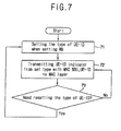
- Figure 7 is a flow chart illustrating a static setting of the type of a user equipment identifier based on an embodiment of the present invention.
- the RLC layer sets a user equipment identifier to be used, then transmits the set indicator to the MAC layer with a MAC SDU, and accordingly a user equipment identifier type field and a user equipment identifier field are set as shown in steps 71 ⁇ 73.
- the user equipment identifier type is altered by changing the radio bearer setting as shown in steps 73 and 71.
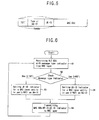
- Figure 6 is a flow chart illustrating a dynamic setting of the type of a user equipment identifier based on the preferred embodiment of the present invention
- the RLC layer receives an RLC SDU and a message type indicator from the RRC layer as shown in step 61.
- the RLC layer checks the message type indicator, judges which one (between a U-RNTI and a C-RNTI) is to be used in the transmission of a pertinent MAC SDU, sets a user equipment identifier indicator and transmits it to the MAC layer with the MAC SDU as shown in steps 62 ⁇ 65.
- the RLC layer segments and reassembles the RLC SDU
- the messages (usually not less than two) can either construct one RLD PDU, or several RLC PDUs can construct one message.
- the type of user equipment identifier indicator used for each message can be different (for example, a first message may be associated with U-RNTI and a second message may be associated with C-RNTI).
- a user equipment identifier indicator is set to construct a header of a MAC PDU by using only a U-RNT) (32 bit) as a broader conceptual identifier.
- the same user equipment identifier indicator is transmitted to the MAC layer with the MAC SDU(substantially same as the RLC PDU).
- a message type indicator and a user equipment identifier indicator refers to the same thing.
- a user equipment identifier indicator of the RLC PDU is set based on the message type indicator.
- data RLC SDU
- a message type indicator as user equipment identification information are transmitted from the RRC layer to the RLC layer. Then the RLC layer sets a user equipment identifier indicator according to the transmitted message type indicator and transmits it to the MAC layer with the data, and appropriate user equipment identification information is added in the MAC layer.
- radio resource waste can be minimized by not setting one kind of user equipment identifier in a lump but setting an appropriate user equipment identifier as occasion demands.
- the preferred embodiments may be implemented as a method, apparatus or article of manufacture using standard programming and/or engineering techniques to produce software, firmware, hardware, or any combination thereof
- article of manufacture refers to code or logic implemented in hardware logic (e.g., an integrated circuit chip, Field Programmable Gate Array (FPGA), Application Specific Integrated Circuit (ASIC), etc.) or a computer readable medium (e.g., magnetic storage medium (e g., hard disk drives, floppy disks, tape, etc.), optical storage (CD-ROMs, optical disks, etc.), volatile and non-volatile memory devices (e.g., EEPROMs, ROMs, PROMs, RAMs, DRAMs, SRAMs, firmware, programmable logic, etc.), Code in the computer readable medium is accessed and executed by a processor.
- hardware logic e.g., an integrated circuit chip, Field Programmable Gate Array (FPGA), Application Specific Integrated Circuit (ASIC), etc.
- FPGA Field Programmable Gate Array
- ASIC Application
- the code in which preferred embodiments are implemented may further be accessible through a transmission media or from a file server over a network.
- the article of manufacture in which the code is implemented may comprise a transmission media, such as a network transmission line, wireless transmission media, signals propagating through space, radio waves, infrared signals, etc.
- a transmission media such as a network transmission line, wireless transmission media, signals propagating through space, radio waves, infrared signals, etc.
Abstract
Description
Claims (33)
- A method for setting a user equipment identifier in a radio communication system having a plurality of protocol layers, the steps comprising:providing data and a message type indicator from a radio resources control (RRC) layer to a radio link control (RLC) layer, wherein the message type indicator is associated with a user equipment identifier indicator;setting in the RLC layer the user equipment identifier indicator in response to the received message type indicator;providing the user equipment identifier indicator and the data to a medium access control (MAC) layer; andadding in the MAC layer a user equipment identifier type and a user equipment identifier to a header of a data unit of the MAC layer in response to the user equipment identifier indicator.
- The method of claim 1, wherein the data unit of the MAC layer comprises the MAC SDU with the user equipment identifier type and the user equipment identifier.
- The method of claim 1, wherein the RLC layer receives the data and the message type indicator associated with the user equipment identifier indicator from the RRC layer and sets the user equipment identifier indicator for distinguishing a user equipment appropriate to a network region to manage the user equipment in the radio communication system.
- The method of claim 1, wherein the MAC layer receives the MAC SDU and the user equipment identifier indicator indicating a user equipment type associated with a radio network temporary identify (RNTI), and setting the user equipment identifier type and the user equipment identifier as part of MAC PDU.
- The method of claim 3, wherein the MAC layer receives the MAC SDU and the user equipment identifier indicator indicating a user equipment type associated with a radio network temporary identify (RNTI), and setting the user equipment identifier type and the user equipment identifier as part of MAC PDU header.
- The method of claim 1, wherein the user equipment type is used in determining radio resource settings of a radio bearer, and the user equipment identifier indicator is transmitted from the RLC layer to the MAC layer
- The method of claim 6, wherein the user equipment identifier indicator is dynamically updated by control information of the RRC layer when the user equipment type has changed
- The method of claim 1, wherein the user equipment type is altered according to the data (RLC SDU) transmitted from the RRC layer to the RLC layer.
- The method of claim 8, wherein a user equipment is distinguished by using the user equipment identifier when the RLC PDU constructed in the MAC layer includes a RRC message having a different user equipment type
- The method of claim 1, wherein a user equipment is distinguished by using a user equipment identifier distinguishable in a cell level when the RLC layer receives data from layers other than the RRC layer.
- A method for setting a user equipment identifier in a radio communication system having a plurality of protocol layers, the steps comprising:providing data and a parameter associated with a user equipment identifier type indicator from a third protocol layer to a second protocol layer, wherein the third protocol layer is an upper protocol layer than the second protocol layer;providing the user equipment identifier indicator and the data from the second protocol layer to a first protocol layer; andadding in the first protocol layer a user equipment identifier type and a user equipment identifier to a first protocol layer data packet in response to the user equipment identifier indicator
- The method of claim 11, wherein the third protocol layer is a radio resource control (RRC) layer.
- The method of claim 11, wherein the second protocol layer is a radio link control (RLC) layer
- The method of claim 11, wherein the first protocol layer is a medium access control (MAC) layer.
- The method of claim 14, wherein the first protocol layer data packet is an MAC service data unit (SDU)
- The method of claim 15, wherein an MAC protocol data unit (PDU) comprises the MAC SDU and the user equipment identifier.
- The method of claim 11, wherein the user equipment identifier indicator is associated with at least one of cell radio network temporary identity (C-RNTI) and UTRAN radio network temporary identity (U-RNTI).
- The method of claim 16, wherein the MAC layer receives the MAC SDU and the user equipment identifier indicator indicating a user equipment type associated with a radio network temporary identify (RNTI), and setting the user equipment identifier type and the user equipment identifier as part of MAC PDU.
- The method of claim 11, wherein the user equipment type is used in determining radio resource settings of a radio bearer, and the user equipment identifier indicator is transmitted from the second protocol layer to the first protocol layer.
- The method of claim 11 wherein the user equipment identifier indicator is dynamically updated by control information of the third protocol layer when the user equipment type used in a radio communication network has changed.
- A radio communication system for identifying user equipment in a radio communication network, the system comprising:a plurality of protocol layers;means for providing data and a message type indicator from a RRC (radio resources control) layer to an RLC (radio link control) layer, wherein the message type indicator is associated with a user equipment identifier indicator;means for setting in the RLC layer the user equipment identifier indicator in response to the received message type indicator;means for providing the user equipment identifier indicator and the data to a MAC (medium access control) layer; andmeans for adding in the MAC layer a user equipment identifier type and a user equipment identifier to a header of a data unit of the MAC layer in response to the user equipment identifier indicator.
- The system of claim 21, wherein the data unit of the MAC layer comprises the MAC SDU with the user equipment identifier type and the user equipment identifier.
- The system of claim 21, wherein the RLC layer receives the data and the message type indicator associated with the user equipment identifier indicator from the RRC layer and sets the user equipment identifier indicator for distinguishing a user equipment appropriate to a network region to properly manage the user equipment in the radio communication system.
- The system of claim 21, wherein the MAC layer receives the MAC SDU and the user equipment identifier indicator indicating a user equipment type associated with a radio network temporary identify (RNTI), and setting the user equipment identifier type and the user equipment identifier as part of MAC PDU.
- The system of claim 23, wherein the MAC layer receives the MAC SDU and the user equipment identifier indicator indicating a user equipment type associated with a radio network temporary identify (RNTI), and setting the user equipment identifier type and the user equipment identifier as part of MAC PDU header
- A radio communication system for identifying user equipment in a radio communication network, the system comprising:a plurality of protocol layers;means for providing data and a parameter associated with a user equipment identifier type indicator from a third protocol layer to a second protocol layer, wherein the third protocol layer is an upper protocol layer than. the second protocol layer;providing the user equipment identifier indicator and the data from the second protocol layer to a first protocol layer; andadding in the first protocol layer a user equipment identifier type and a user equipment identifier to a first protocol layer data packet in response to the user equipment identifier indicator.
- The system of claim 26, wherein the third protocol layer is a radio resource control (RRC) layer, the second protocol layer is a radio link control (RLC) layer, and the first protocol layer is a medium access control (MAC) layer.
- The system of claim 27, wherein the first protocol layer data packet is an MAC service data unit (SDU).
- The system of claim 28, wherein an MAC protocol data unit (PDU) comprises the MAC SDU and the user equipment identifier.
- The system of claim 26, wherein the user equipment identifier indicator is associated with at least one of cell radio network temporary identity (C-RNTI) and UTRAN radio network temporary identity (U-RNTI)
- The system of claim 28, wherein the MAC layer receives the MAC SDU and the user equipment identifier indicator indicating a user equipment type associated with a radio network temporary identify (RNTI), and setting the user equipment identifier type and the user equipment identifier as part of MAC PDU.
- The system of claim 26, wherein the user equipment type is used in determining radio resource settings of a radio bearer, and the user equipment identifier indicator is transmitted from the second protocol layer to the first protocol layer
- The system of claim 26, wherein the user equipment identifier indicator is dynamically updated by control information of the third protocol layer when the user equipment type used in a radio communication network has changed.
Priority Applications (2)
| Application Number | Priority Date | Filing Date | Title |
|---|---|---|---|
| EP20050010024 EP1564941B1 (en) | 2001-07-07 | 2002-07-04 | Method for setting user equipment identifier in radio communication system |
| DK02014799T DK1274203T3 (en) | 2001-07-07 | 2002-07-04 | Method of setting a user equipment identifier in a radio communication system |
Applications Claiming Priority (2)
| Application Number | Priority Date | Filing Date | Title |
|---|---|---|---|
| KR2001040710 | 2001-07-07 | ||
| KR20010040710A KR100802618B1 (en) | 2001-07-07 | 2001-07-07 | Method and apparatus for setting user equipment identifier in a wireless communications system |
Related Child Applications (2)
| Application Number | Title | Priority Date | Filing Date |
|---|---|---|---|
| EP20050010024 Division EP1564941B1 (en) | 2001-07-07 | 2002-07-04 | Method for setting user equipment identifier in radio communication system |
| EP05010024.7 Division-Into | 2005-05-09 |
Publications (2)
| Publication Number | Publication Date |
|---|---|
| EP1274203A1 true EP1274203A1 (en) | 2003-01-08 |
| EP1274203B1 EP1274203B1 (en) | 2005-09-28 |
Family
ID=36101294
Family Applications (2)
| Application Number | Title | Priority Date | Filing Date |
|---|---|---|---|
| EP02014799A Expired - Lifetime EP1274203B1 (en) | 2001-07-07 | 2002-07-04 | Method for setting user equipment identifier in radio communication system |
| EP20050010024 Expired - Lifetime EP1564941B1 (en) | 2001-07-07 | 2002-07-04 | Method for setting user equipment identifier in radio communication system |
Family Applications After (1)
| Application Number | Title | Priority Date | Filing Date |
|---|---|---|---|
| EP20050010024 Expired - Lifetime EP1564941B1 (en) | 2001-07-07 | 2002-07-04 | Method for setting user equipment identifier in radio communication system |
Country Status (11)
| Country | Link |
|---|---|
| US (6) | US7551643B2 (en) |
| EP (2) | EP1274203B1 (en) |
| JP (2) | JP4248198B2 (en) |
| KR (1) | KR100802618B1 (en) |
| CN (1) | CN1184836C (en) |
| AT (2) | ATE405071T1 (en) |
| DE (2) | DE60228342D1 (en) |
| DK (1) | DK1274203T3 (en) |
| ES (1) | ES2248454T3 (en) |
| HK (1) | HK1079372A1 (en) |
| PT (1) | PT1274203E (en) |
Cited By (7)
| Publication number | Priority date | Publication date | Assignee | Title |
|---|---|---|---|---|
| WO2003056721A1 (en) * | 2001-12-31 | 2003-07-10 | Nokia Corporation | Uplink access control |
| EP1884088A1 (en) * | 2005-05-27 | 2008-02-06 | Nokia Corporation | Expanded signalling capability for network element, user equipment and system |
| EP1892990A1 (en) * | 2005-06-17 | 2008-02-27 | NTT DoCoMo INC. | Channel transmission apparatus and channel transmission method |
| CN100459471C (en) * | 2003-07-10 | 2009-02-04 | 华为技术有限公司 | Method for processing RRC connection request message |
| US7792079B2 (en) | 2004-06-08 | 2010-09-07 | Infineon Technologies Ag | Communication system |
| US8406179B2 (en) | 2007-08-07 | 2013-03-26 | Samsung Electronics Co., Ltd. | Method and apparatus for performing random access procedure in a mobile communication system |
| TWI411259B (en) * | 2009-03-16 | 2013-10-01 | Htc Corp | Method of handling packet error in a wireless communication system and related communication device |
Families Citing this family (107)
| Publication number | Priority date | Publication date | Assignee | Title |
|---|---|---|---|---|
| TWI390912B (en) * | 2002-08-09 | 2013-03-21 | Interdigital Tech Corp | Efficient memory allocation in a wireless transmit/receiver unit |
| EP1561355B1 (en) * | 2002-11-05 | 2016-03-09 | Telefonaktiebolaget LM Ericsson (publ) | Collective notification of node reset to subset of connections in radio access network |
| US8111668B2 (en) * | 2003-02-14 | 2012-02-07 | Alcatel Lucent | Signaling methods for wireless communication systems |
| HUE044779T2 (en) | 2003-04-10 | 2019-11-28 | Ericsson Telefon Ab L M | Method and device for retransmission |
| CN102255714B (en) * | 2003-04-10 | 2014-11-26 | 艾利森电话股份有限公司 | Retransmission method and system |
| KR100703380B1 (en) * | 2003-05-14 | 2007-04-03 | 삼성전자주식회사 | Apparatus and method for transmitting/receiving control information for multimedia broadcast/multicast service |
| KR20050018050A (en) * | 2003-08-12 | 2005-02-23 | 삼성전자주식회사 | Method for setting broadcasting service header information in a mobile communication system |
| KR101059876B1 (en) * | 2004-06-16 | 2011-08-29 | 엘지전자 주식회사 | Data Transmission Volume Selection Method for Guaranteeing Service Quality of Mobile Communication System |
| WO2006098538A1 (en) * | 2005-03-12 | 2006-09-21 | Lg Electronics Inc. | A method for transmitting information in a multiple antenna system |
| KR101208520B1 (en) * | 2005-03-12 | 2012-12-05 | 엘지전자 주식회사 | Method for Communicating Feedback Information |
| US7886311B2 (en) | 2005-03-29 | 2011-02-08 | Microsoft Corporation | Synchronous RIL proxy |
| US7821974B2 (en) * | 2005-03-29 | 2010-10-26 | Microsoft Corporation | UMTS RIL extension |
| US20090168704A1 (en) * | 2005-08-24 | 2009-07-02 | Young Dae Lee | Method of transmitting control information for scheduling |
| KR101203841B1 (en) | 2006-01-05 | 2012-11-21 | 엘지전자 주식회사 | Method of transmitting and receiving paging message in wireless communication system |
| KR101265628B1 (en) | 2006-01-05 | 2013-05-22 | 엘지전자 주식회사 | method for scheduling radio resourse in the mobile communication system |
| KR101268200B1 (en) * | 2006-01-05 | 2013-05-27 | 엘지전자 주식회사 | Radio resource allocating method in mobile communication system |
| KR100912784B1 (en) | 2006-01-05 | 2009-08-18 | 엘지전자 주식회사 | Data transmission method and data retransmission method |
| WO2007078171A2 (en) | 2006-01-05 | 2007-07-12 | Lg Electronics Inc. | Method of transmitting feedback information in a wireless communication system |
| KR101333918B1 (en) * | 2006-01-05 | 2013-11-27 | 엘지전자 주식회사 | Point-to-multipoint service communication of mobile communication system |
| AU2007203852B2 (en) | 2006-01-05 | 2010-08-26 | Lg Electronics Inc. | Transmitting data in a mobile communication system |
| KR101187076B1 (en) | 2006-01-05 | 2012-09-27 | 엘지전자 주식회사 | Method for transmitting signals in the moblie communication system |
| KR101319870B1 (en) | 2006-01-05 | 2013-10-18 | 엘지전자 주식회사 | Method for handover in mobile communication system |
| KR101211807B1 (en) | 2006-01-05 | 2012-12-12 | 엘지전자 주식회사 | Method for managing synchronization state for mobile terminal in mobile communication system |
| AU2007203861B2 (en) | 2006-01-05 | 2009-11-26 | Interdigital Patent Holdings, Inc. | Transmitting information in mobile communications system |
| JP4806030B2 (en) | 2006-01-05 | 2011-11-02 | エルジー エレクトロニクス インコーポレイティド | Method for transferring signals in a mobile communication system |
| KR101216751B1 (en) * | 2006-02-07 | 2012-12-28 | 엘지전자 주식회사 | Method for avoiding collision using identifier in mobile network |
| KR101358469B1 (en) | 2006-02-07 | 2014-02-06 | 엘지전자 주식회사 | Method for selection and signaling of downlink and uplink bandwidth in wireless networks |
| US8493854B2 (en) | 2006-02-07 | 2013-07-23 | Lg Electronics Inc. | Method for avoiding collision using identifier in mobile network |
| KR100880979B1 (en) * | 2006-02-27 | 2009-02-03 | 삼성전자주식회사 | Authentication method and apparatus in a mobile broadcast system |
| US8805367B2 (en) | 2006-03-14 | 2014-08-12 | Sharp Kabushiki Kaisha | Method and apparatus for allocating terminal identifiers based on communication function |
| KR101387475B1 (en) | 2006-03-22 | 2014-04-22 | 엘지전자 주식회사 | method of processing data in mobile communication system having a plurality of network entities |
| WO2007148881A2 (en) | 2006-06-21 | 2007-12-27 | Lg Electronics Inc. | Method of supporting data retransmission in a mobile communication system |
| KR101369135B1 (en) | 2006-06-21 | 2014-03-05 | 엘지전자 주식회사 | Mehtod for supproting quality of multimeida broadcast multicast service(mbms) in mobile communications system and terminal thereof |
| EP2033341B1 (en) | 2006-06-21 | 2018-03-21 | LG Electronics Inc. | Method of transmitting and receiving radio access information using a message separation in a wireless mobile communications system |
| KR20070121505A (en) | 2006-06-21 | 2007-12-27 | 엘지전자 주식회사 | Method for reconfiguring radio link |
| WO2007148932A1 (en) * | 2006-06-21 | 2007-12-27 | Electronics And Telecommunications Research Institute | Method for paging terminal of rrc connected state in lte system |
| KR20070121513A (en) | 2006-06-21 | 2007-12-27 | 엘지전자 주식회사 | Uplink access method of mobile communication system |
| KR101265643B1 (en) * | 2006-08-22 | 2013-05-22 | 엘지전자 주식회사 | A mothod of executing handover and controlling thereof in mobile communication system |
| KR101387500B1 (en) | 2006-08-22 | 2014-04-21 | 엘지전자 주식회사 | Method of transmitting and receiving control information in wireless communicaiton system |
| KR101430449B1 (en) * | 2006-10-02 | 2014-08-14 | 엘지전자 주식회사 | Method for transmitting and receiving paging message in wireless communication system |
| US20080096557A1 (en) * | 2006-10-04 | 2008-04-24 | Nokia Corporation | Efficient and dynamic identification of allocations in a wireless packet communication system |
| KR100938754B1 (en) | 2006-10-30 | 2010-01-26 | 엘지전자 주식회사 | Data transmission method and data receiving method using discontinuous reception |
| WO2008054114A2 (en) * | 2006-10-30 | 2008-05-08 | Lg Electronics Inc. | Methods for re-direction of uplink access and for controlling random access in mobile communication system |
| WO2008054112A2 (en) * | 2006-10-30 | 2008-05-08 | Lg Electronics Inc. | Methods of performing random access in a wireless communication system |
| EP2078342B1 (en) * | 2006-10-30 | 2015-08-26 | LG Electronics Inc. | Method for transmitting random access channel message and response message, and mobile communication terminal |
| WO2008097030A1 (en) * | 2007-02-07 | 2008-08-14 | Lg Electronics Inc. | Optimized random access channel (rach) access |
| KR101112145B1 (en) * | 2007-02-09 | 2012-02-22 | 삼성전자주식회사 | A method and apparatus for detecting contention at random access procedure in a wireless communications system |
| BRPI0807380A2 (en) * | 2007-03-16 | 2014-05-20 | Ericsson Telefon Ab L M | METHODS FOR TRANSMITTING A CONTROL MESSAGE AND TO DETECT THAT A RECEIVED RADIO BLOCK CONTAINS A CONTROL BLOCK AND PROCESSING UNIT. |
| US8045518B2 (en) | 2007-03-23 | 2011-10-25 | Innovative Sonic Limited | Method of deactivating high-speed downlink operation in CELL—FACH state for a wireless communications system and related apparatus |
| WO2008133480A1 (en) | 2007-04-30 | 2008-11-06 | Lg Electronics Inc. | Method for transmitting or receiving data unit using header field existence indicator |
| US8184570B2 (en) * | 2007-04-30 | 2012-05-22 | Lg Electronics Inc. | Method of transmitting data in wireless communication system supporting multimedia broadcast/multicast service |
| KR101469281B1 (en) * | 2007-04-30 | 2014-12-04 | 엘지전자 주식회사 | Method for state transition of mobile terminal |
| KR101464748B1 (en) * | 2007-04-30 | 2014-11-24 | 엘지전자 주식회사 | Method for triggering a measurement report of mobile terminal |
| USRE45347E1 (en) | 2007-04-30 | 2015-01-20 | Lg Electronics Inc. | Methods of transmitting data blocks in wireless communication system |
| WO2008133485A1 (en) * | 2007-04-30 | 2008-11-06 | Lg Electronics Inc. | Methods of generating data block in mobile communication system |
| KR101461236B1 (en) | 2007-04-30 | 2014-11-12 | 엘지전자 주식회사 | Methods for performing an Authentication of entities during establishment of wireless call connection |
| WO2008133478A2 (en) * | 2007-04-30 | 2008-11-06 | Lg Electronics Inc. | Method of transmitting data in a wireless communication system |
| KR20080097338A (en) * | 2007-05-01 | 2008-11-05 | 엘지전자 주식회사 | Discontinuous data transmittion/reception method |
| KR100917205B1 (en) * | 2007-05-02 | 2009-09-15 | 엘지전자 주식회사 | Method of configuring a data block in wireless communication system |
| WO2008136598A1 (en) * | 2007-05-03 | 2008-11-13 | Lg Electronics Inc. | Method of data processing in a wireless communication system |
| KR101526971B1 (en) * | 2007-06-18 | 2015-06-11 | 엘지전자 주식회사 | Method for transmitting/receiving broadcast or multicast service and terminal thereof |
| WO2008156309A1 (en) * | 2007-06-18 | 2008-12-24 | Lg Electronics Inc. | Control channel reception method for receiving broadcast or multicast service |
| WO2008156308A2 (en) | 2007-06-18 | 2008-12-24 | Lg Electronics Inc. | Paging information transmission method for effective call setup |
| KR101486352B1 (en) | 2007-06-18 | 2015-01-26 | 엘지전자 주식회사 | Method of controlling uplink synchronization state at a user equipment in a mobile communication system |
| KR101341515B1 (en) | 2007-06-18 | 2013-12-16 | 엘지전자 주식회사 | Method of updating repeatedly-transmitted information in wireless communicaiton system |
| KR101470638B1 (en) * | 2007-06-18 | 2014-12-08 | 엘지전자 주식회사 | Method for enhancing radio resource and informing status report in mobile telecommunications system and receiver of mobile telecommunications |
| EP2627146B1 (en) | 2007-06-18 | 2017-09-20 | LG Electronics Inc. | Method and user equipment for performing uplink synchronization in wireless communication system |
| WO2008156314A2 (en) | 2007-06-20 | 2008-12-24 | Lg Electronics Inc. | Effective system information reception method |
| US8792339B2 (en) * | 2007-08-10 | 2014-07-29 | Arris Enterprises, Inc. | Method and system for moving distinctive traffic flows to a different priority service flow |
| KR101514841B1 (en) | 2007-08-10 | 2015-04-23 | 엘지전자 주식회사 | Method for re-attempting a random access effectively |
| WO2009022826A1 (en) | 2007-08-10 | 2009-02-19 | Lg Electronics Inc. | Method for controlling harq operation in dynamic radio resource allocation |
| KR101490253B1 (en) | 2007-08-10 | 2015-02-05 | 엘지전자 주식회사 | Method of transmitting and receiving control information in a wireless communication system |
| WO2009022877A2 (en) | 2007-08-14 | 2009-02-19 | Lg Electronics Inc. | A method of transmitting and processing data block of specific protocol layer in wireless communication system |
| KR101461970B1 (en) | 2007-09-13 | 2014-11-14 | 엘지전자 주식회사 | Method of performing polling procedure in a wireless communication system |
| KR100937432B1 (en) | 2007-09-13 | 2010-01-18 | 엘지전자 주식회사 | Method of allocating radio resources in a wireless communication system |
| KR101591824B1 (en) | 2007-09-18 | 2016-02-04 | 엘지전자 주식회사 | Method of performing polling procedure in a wireless communication system |
| KR101435844B1 (en) | 2007-09-18 | 2014-08-29 | 엘지전자 주식회사 | Method of transmitting a data block in a wireless communication system |
| KR101513033B1 (en) | 2007-09-18 | 2015-04-17 | 엘지전자 주식회사 | A method for qos guarantees in a multilayer structure |
| KR101396062B1 (en) | 2007-09-18 | 2014-05-26 | 엘지전자 주식회사 | Effective data block transmission method using a header indicator |
| KR101387537B1 (en) * | 2007-09-20 | 2014-04-21 | 엘지전자 주식회사 | A method for handling correctly received but header compression failed packets |
| US8687565B2 (en) | 2007-09-20 | 2014-04-01 | Lg Electronics Inc. | Method of effectively transmitting radio resource allocation request in mobile communication system |
| US8400982B2 (en) * | 2007-09-20 | 2013-03-19 | Lg Electronics Inc. | Method for handling correctly received but header compression failed packets |
| KR20090041323A (en) | 2007-10-23 | 2009-04-28 | 엘지전자 주식회사 | Method of effectively transmitting identification information of terminal during the generation of data block |
| KR101487557B1 (en) | 2007-10-23 | 2015-01-29 | 엘지전자 주식회사 | Method for transmitting data of common control channel |
| WO2009057941A2 (en) | 2007-10-29 | 2009-05-07 | Lg Electronics Inc. | A method for repairing an error depending on a radion bearer type |
| EP2266224B1 (en) | 2008-03-17 | 2017-06-14 | LG Electronics Inc. | Method of transmitting rlc data |
| KR101163275B1 (en) | 2008-03-17 | 2012-07-05 | 엘지전자 주식회사 | Method for transmitting pdcp status report |
| US8791470B2 (en) * | 2009-10-05 | 2014-07-29 | Zena Technologies, Inc. | Nano structured LEDs |
| US8498313B2 (en) * | 2008-10-23 | 2013-07-30 | Qualcomm Incorporated | Fast uplink data transmission using E-DCH enhanced random access without a UE specific E-RNTI |
| WO2010069400A1 (en) * | 2008-12-19 | 2010-06-24 | Telefonaktiebolaget Lm Ericsson (Publ) | Method and entity for conveying data units |
| US20100260108A1 (en) * | 2009-04-13 | 2010-10-14 | Qualcomm Incorporated | Setting up a reverse link data transmission within a wireless communications system |
| WO2010126068A1 (en) * | 2009-04-27 | 2010-11-04 | 日本電気株式会社 | Reception device, reception method, and program |
| CN101998636B (en) * | 2009-08-14 | 2013-07-31 | 电信科学技术研究院 | Using method, system and equipment of terminal identification |
| US8560708B2 (en) * | 2010-06-29 | 2013-10-15 | Alcatel Lucent | Method and apparatus for allocating bundles of sessions in a network element |
| JP2014510450A (en) * | 2011-02-09 | 2014-04-24 | インターデイジタル パテント ホールディングス インコーポレイテッド | Method for paging for downlink data to M2M devices |
| EP2557870B1 (en) * | 2011-08-10 | 2020-07-08 | Alcatel Lucent | Configuring transmissions |
| CN103891097B (en) | 2012-10-19 | 2016-08-17 | 株式会社Lg化学 | The method of distribution unique identifier and the battery management system of use the method |
| CN104012142A (en) * | 2012-12-18 | 2014-08-27 | 华为技术有限公司 | Public operation processing method and device |
| US9497682B2 (en) | 2013-06-07 | 2016-11-15 | Intel Corporation | Central processing unit and methods for supporting coordinated multipoint transmission in an LTE network |
| US10485018B2 (en) * | 2014-01-16 | 2019-11-19 | Samsung Electronics Co., Ltd. | Apparatus and method for operating user plane protocol stack in connectionless communication system |
| US20160006842A1 (en) * | 2014-07-02 | 2016-01-07 | Qualcomm Incorporated | Frame format supporting enhanced features in a communication network |
| EP3021612B1 (en) * | 2014-11-12 | 2018-03-21 | HTC Corporation | Device and method of handling network configurations |
| US10514683B2 (en) | 2015-09-16 | 2019-12-24 | Profire Energy, Inc. | Distributed networking system and method to implement a safety state environment |
| US10432754B2 (en) | 2015-09-16 | 2019-10-01 | Profire Energy, Inc | Safety networking protocol and method |
| CN107231664B (en) * | 2017-05-25 | 2019-11-08 | 上海连尚网络科技有限公司 | A kind of method and apparatus for user equipment progress flow control |
| CN110312226B (en) | 2018-03-20 | 2021-02-26 | 华为技术有限公司 | Method and communication device for transmitting data |
| US10805163B2 (en) * | 2018-08-21 | 2020-10-13 | Hewlett Packard Enterprise Development Lp | Identifying device types based on behavior attributes |
Citations (1)
| Publication number | Priority date | Publication date | Assignee | Title |
|---|---|---|---|---|
| WO2000054536A1 (en) * | 1999-03-08 | 2000-09-14 | Nokia Networks Oy | Method for establishing a communication between a user equipment and a radio network |
Family Cites Families (21)
| Publication number | Priority date | Publication date | Assignee | Title |
|---|---|---|---|---|
| KR100619598B1 (en) * | 1998-10-01 | 2006-12-01 | 엘지전자 주식회사 | Signal Format Method in Mobile Communication System |
| FI114077B (en) * | 1999-03-10 | 2004-07-30 | Nokia Corp | ID booking method |
| GB2352585B (en) | 1999-05-28 | 2003-11-12 | Nec Corp | Mobile telecommunications system |
| GB9913221D0 (en) * | 1999-06-07 | 1999-08-04 | Nokia Telecommunications Oy | Cell update in a cellular communications system |
| KR100317267B1 (en) | 1999-10-02 | 2001-12-22 | 서평원 | Protection method for Common Packet Channel |
| FI109438B (en) * | 1999-10-15 | 2002-07-31 | Nokia Corp | A method for transmitting information on a packet data channel |
| GB2355623B (en) * | 1999-10-19 | 2003-07-16 | Ericsson Telefon Ab L M | Packet transmission in a UMTS network |
| EP1094675A1 (en) * | 1999-10-21 | 2001-04-25 | Hyundai Electronics Industries Co., Ltd. | Method for transmitting radio resource control message in asynchronous mobile communication system |
| US20030012217A1 (en) * | 1999-10-29 | 2003-01-16 | Christoffer Andersson | Channel-type switching to a common channel based on common channel load |
| US6968190B1 (en) * | 1999-11-29 | 2005-11-22 | Nokia Mobile Phones, Ltd. | Transfer of optimization algorithm parameters during handover of a mobile station between radio network subsystems |
| SG158743A1 (en) | 2000-01-14 | 2010-02-26 | Interdigital Tech Corp | Wireless communication system with selectively sized data transport blocks |
| US6829482B2 (en) * | 2000-05-16 | 2004-12-07 | Telefonaktiebolaget Lm Ericsson (Publ) | Switching from dedicated to common channels when radio resources are controlled by drift radio network |
| FR2809576B1 (en) * | 2000-05-23 | 2002-11-15 | Nortel Matra Cellular | METHOD FOR CONTROLLING A CHANNEL BETWEEN A RADIO TERMINAL AND A CELLULAR RADIO COMMUNICATION INFRASTRUCTURE, AND ACCESS NETWORK IMPLEMENTING SUCH A METHOD |
| FR2809577B1 (en) * | 2000-05-25 | 2002-10-18 | Mitsubishi Electric Inf Tech | DATA TRANSMISSION METHOD COMBATING THE DEGRADATION OF QUALITY OF SERVICE |
| EP1170919A1 (en) * | 2000-07-04 | 2002-01-09 | TELEFONAKTIEBOLAGET LM ERICSSON (publ) | Method and device for improving the transmission efficiency in a communication system with a layered protocol stack |
| US6862450B2 (en) * | 2001-02-07 | 2005-03-01 | Nokia Mobile Phones Ltd. | Resetting signaling link upon SRNS relocation procedure |
| US6701151B2 (en) * | 2001-03-27 | 2004-03-02 | Ericsson Inc. | Short access for realizing a signaling radio bearer in geran |
| US7089002B2 (en) * | 2001-05-11 | 2006-08-08 | Telefonaktiebolaget Lm Ericsson (Publ) | Releasing plural radio connections with omnibus release message |
| US6961349B2 (en) | 2001-05-30 | 2005-11-01 | Telefonaktiebolaget Lm Ericsson (Publ) | Handling TCP protocol for connections transmitted in parallel over radio link |
| GB2380104B (en) * | 2001-07-06 | 2003-09-10 | Samsung Electronics Co Ltd | Method for resetting MAC layer entity in a communication system |
| US7054630B2 (en) * | 2002-05-13 | 2006-05-30 | Qualcomm Incorporated | Selective processing of the common control channel |
-
2001
- 2001-07-07 KR KR20010040710A patent/KR100802618B1/en active IP Right Grant
-
2002
- 2002-07-04 DK DK02014799T patent/DK1274203T3/en active
- 2002-07-04 DE DE60228342T patent/DE60228342D1/en not_active Expired - Lifetime
- 2002-07-04 AT AT05010024T patent/ATE405071T1/en not_active IP Right Cessation
- 2002-07-04 DE DE2002606329 patent/DE60206329T2/en not_active Expired - Lifetime
- 2002-07-04 EP EP02014799A patent/EP1274203B1/en not_active Expired - Lifetime
- 2002-07-04 AT AT02014799T patent/ATE305690T1/en active
- 2002-07-04 ES ES02014799T patent/ES2248454T3/en not_active Expired - Lifetime
- 2002-07-04 EP EP20050010024 patent/EP1564941B1/en not_active Expired - Lifetime
- 2002-07-04 PT PT02014799T patent/PT1274203E/en unknown
- 2002-07-05 JP JP2002198007A patent/JP4248198B2/en not_active Expired - Lifetime
- 2002-07-08 CN CNB021406405A patent/CN1184836C/en not_active Expired - Lifetime
- 2002-07-08 US US10/191,260 patent/US7551643B2/en active Active
-
2006
- 2006-02-09 HK HK06101749A patent/HK1079372A1/en not_active IP Right Cessation
-
2008
- 2008-07-29 JP JP2008195416A patent/JP4701272B2/en not_active Expired - Lifetime
-
2009
- 2009-04-21 US US12/427,632 patent/US7715435B2/en not_active Expired - Lifetime
- 2009-09-14 US US12/585,385 patent/US7869398B2/en not_active Expired - Fee Related
- 2009-09-14 US US12/585,392 patent/US7876782B2/en not_active Ceased
- 2009-09-14 US US12/585,397 patent/US7873008B2/en not_active Expired - Fee Related
-
2011
- 2011-12-19 US US13/329,975 patent/USRE44488E1/en not_active Expired - Fee Related
Patent Citations (1)
| Publication number | Priority date | Publication date | Assignee | Title |
|---|---|---|---|---|
| WO2000054536A1 (en) * | 1999-03-08 | 2000-09-14 | Nokia Networks Oy | Method for establishing a communication between a user equipment and a radio network |
Non-Patent Citations (4)
| Title |
|---|
| "Universal Mobile Telecommunication System (UMTS); MAC protocol specification (3GPP TS 25.321 Version 3.8.0 Release 1999)", ETSI TS 125 321 V3.8.0, June 2001 (2001-06-01), pages 1 - 42, XP002212668 * |
| "Universal Mobile Telecommunication System (UMTS); RLC protocol specification (3GPP TS 25.322 Version 3.7.0 Release 1999)", ETSI TS 125 322 V3.7.0, June 2001 (2001-06-01), pages 1 - 58, XP002212671 * |
| LG ELECTRONICS INC.: "3GPP TSG RAN WG2 Meeting#25; 25.322", R2-012540; CR161, 26 November 2001 (2001-11-26) - 30 November 2001 (2001-11-30), Makuhari, Japan, pages 1 - 5, XP002212669 * |
| TSG-RAN WG2: "3GPP TSG RAN WG2 Meeting#25; 25.322", R2-012738; CR161, 26 November 2001 (2001-11-26) - 30 November 2001 (2001-11-30), Makuhari, Japan, pages 1 - 5, XP002212670 * |
Cited By (17)
| Publication number | Priority date | Publication date | Assignee | Title |
|---|---|---|---|---|
| WO2003056721A1 (en) * | 2001-12-31 | 2003-07-10 | Nokia Corporation | Uplink access control |
| CN100459471C (en) * | 2003-07-10 | 2009-02-04 | 华为技术有限公司 | Method for processing RRC connection request message |
| US7792079B2 (en) | 2004-06-08 | 2010-09-07 | Infineon Technologies Ag | Communication system |
| EP1886449A4 (en) * | 2005-05-27 | 2012-01-04 | Nokia Corp | Expanded signalling capability for network element, user equipment and system |
| US8483141B2 (en) | 2005-05-27 | 2013-07-09 | Nokia Corporation | Expanded signalling capability for network element, user equipment and system |
| EP1886449A2 (en) * | 2005-05-27 | 2008-02-13 | Nokia Corporation | Expanded signalling capability for network element, user equipment and system |
| EP1884088A4 (en) * | 2005-05-27 | 2011-12-28 | Nokia Corp | Expanded signalling capability for network element, user equipment and system |
| EP1884088A1 (en) * | 2005-05-27 | 2008-02-06 | Nokia Corporation | Expanded signalling capability for network element, user equipment and system |
| CN101213799A (en) * | 2005-05-27 | 2008-07-02 | 诺基亚公司 | Expanded signalling capability for network element, user equipment and system |
| EP1892990A1 (en) * | 2005-06-17 | 2008-02-27 | NTT DoCoMo INC. | Channel transmission apparatus and channel transmission method |
| EP1892990A4 (en) * | 2005-06-17 | 2012-04-25 | Ntt Docomo Inc | Channel transmission apparatus and channel transmission method |
| US8406179B2 (en) | 2007-08-07 | 2013-03-26 | Samsung Electronics Co., Ltd. | Method and apparatus for performing random access procedure in a mobile communication system |
| EP2023553A3 (en) * | 2007-08-07 | 2013-06-12 | Samsung Electronics Co., Ltd. | Method and apparatus for performing random access procedure in a mobile communication system |
| US9320025B2 (en) | 2007-08-07 | 2016-04-19 | Samsung Electronics Co., Ltd. | Method and apparatus for performing random access procedure in a mobile communication system |
| US9839013B2 (en) | 2007-08-07 | 2017-12-05 | Samsung Electronics Co., Ltd. | Method and apparatus for performing random access procedure in a mobile communication system |
| TWI411259B (en) * | 2009-03-16 | 2013-10-01 | Htc Corp | Method of handling packet error in a wireless communication system and related communication device |
| US8553574B2 (en) | 2009-03-16 | 2013-10-08 | Htc Corporation | Method of handling packet error in a wireless communication system and related communication device |
Also Published As
| Publication number | Publication date |
|---|---|
| ATE305690T1 (en) | 2005-10-15 |
| US7876782B2 (en) | 2011-01-25 |
| CN1184836C (en) | 2005-01-12 |
| ATE405071T1 (en) | 2008-08-15 |
| JP2008312241A (en) | 2008-12-25 |
| DK1274203T3 (en) | 2005-10-17 |
| DE60206329D1 (en) | 2006-02-09 |
| EP1564941A2 (en) | 2005-08-17 |
| CN1396780A (en) | 2003-02-12 |
| EP1274203B1 (en) | 2005-09-28 |
| DE60228342D1 (en) | 2008-09-25 |
| US20100008304A1 (en) | 2010-01-14 |
| KR100802618B1 (en) | 2008-02-13 |
| DE60206329T2 (en) | 2006-06-22 |
| US7869398B2 (en) | 2011-01-11 |
| US7715435B2 (en) | 2010-05-11 |
| KR20030004945A (en) | 2003-01-15 |
| ES2248454T3 (en) | 2006-03-16 |
| JP4248198B2 (en) | 2009-04-02 |
| US20090213799A1 (en) | 2009-08-27 |
| US20030007510A1 (en) | 2003-01-09 |
| EP1564941A3 (en) | 2006-02-08 |
| US20100008320A1 (en) | 2010-01-14 |
| EP1564941B1 (en) | 2008-08-13 |
| US7873008B2 (en) | 2011-01-18 |
| JP4701272B2 (en) | 2011-06-15 |
| US20100008303A1 (en) | 2010-01-14 |
| PT1274203E (en) | 2005-11-30 |
| US7551643B2 (en) | 2009-06-23 |
| USRE44488E1 (en) | 2013-09-10 |
| JP2003116172A (en) | 2003-04-18 |
| HK1079372A1 (en) | 2006-03-31 |
Similar Documents
| Publication | Publication Date | Title |
|---|---|---|
| US7873008B2 (en) | Method for setting user equipment identifier in radio communication system | |
| JP4181548B2 (en) | Logical channel multiplexing apparatus and method for mobile communication system | |
| US6717925B1 (en) | Point-to-multipoint mobile radio transmission | |
| RU2280327C2 (en) | Processing data blocks for transferring them over same channel | |
| US7394778B2 (en) | Mapping of point of multipoint service identifications | |
| AU2005330412B2 (en) | Mapping of MBMS service identifications | |
| CN1989712B (en) | Method and apparatus for providing enhanced messages on common control channel in wireless communication system |
Legal Events
| Date | Code | Title | Description |
|---|---|---|---|
| PUAI | Public reference made under article 153(3) epc to a published international application that has entered the european phase |
Free format text: ORIGINAL CODE: 0009012 |
|
| AK | Designated contracting states |
Kind code of ref document: A1 Designated state(s): AT BE BG CH CY CZ DE DK EE ES FI FR GB GR IE IT LI LU MC NL PT SE SK TR |
|
| AX | Request for extension of the european patent |
Free format text: AL;LT;LV;MK;RO;SI |
|
| 17P | Request for examination filed |
Effective date: 20030626 |
|
| 17Q | First examination report despatched |
Effective date: 20030729 |
|
| AKX | Designation fees paid |
Designated state(s): AT BE BG CH CY CZ DE DK EE ES FI FR GB GR IE IT LI LU MC NL PT SE SK TR |
|
| GRAP | Despatch of communication of intention to grant a patent |
Free format text: ORIGINAL CODE: EPIDOSNIGR1 |
|
| GRAS | Grant fee paid |
Free format text: ORIGINAL CODE: EPIDOSNIGR3 |
|
| GRAA | (expected) grant |
Free format text: ORIGINAL CODE: 0009210 |
|
| AK | Designated contracting states |
Kind code of ref document: B1 Designated state(s): AT BE BG CH CY CZ DE DK EE ES FI FR GB GR IE IT LI LU MC NL PT SE SK TR |
|
| REG | Reference to a national code |
Ref country code: GB Ref legal event code: FG4D |
|
| REG | Reference to a national code |
Ref country code: CH Ref legal event code: EP |
|
| REG | Reference to a national code |
Ref country code: DK Ref legal event code: T3 |
|
| REG | Reference to a national code |
Ref country code: IE Ref legal event code: FG4D |
|
| REG | Reference to a national code |
Ref country code: CH Ref legal event code: NV Representative=s name: A. BRAUN, BRAUN, HERITIER, ESCHMANN AG PATENTANWAE |
|
| REG | Reference to a national code |
Ref country code: SE Ref legal event code: TRGR |
|
| REG | Reference to a national code |
Ref country code: GR Ref legal event code: EP Ref document number: 20050403592 Country of ref document: GR |
|
| REF | Corresponds to: |
Ref document number: 60206329 Country of ref document: DE Date of ref document: 20060209 Kind code of ref document: P |
|
| REG | Reference to a national code |
Ref country code: ES Ref legal event code: FG2A Ref document number: 2248454 Country of ref document: ES Kind code of ref document: T3 |
|
| ET | Fr: translation filed | ||
| PLBE | No opposition filed within time limit |
Free format text: ORIGINAL CODE: 0009261 |
|
| STAA | Information on the status of an ep patent application or granted ep patent |
Free format text: STATUS: NO OPPOSITION FILED WITHIN TIME LIMIT |
|
| 26N | No opposition filed |
Effective date: 20060629 |
|
| REG | Reference to a national code |
Ref country code: CH Ref legal event code: PFA Owner name: LG ELECTRONICS INC. Free format text: LG ELECTRONICS INC.#20, YOIDO-DONG, YOUNGDUNGPO-KU#SEOUL 150-010 (KR) -TRANSFER TO- LG ELECTRONICS INC.#20, YOIDO-DONG, YOUNGDUNGPO-KU#SEOUL 150-010 (KR) |
|
| REG | Reference to a national code |
Ref country code: CH Ref legal event code: PCAR Free format text: NEW ADDRESS: HOLBEINSTRASSE 36-38, 4051 BASEL (CH) |
|
| REG | Reference to a national code |
Ref country code: FR Ref legal event code: PLFP Year of fee payment: 15 |
|
| REG | Reference to a national code |
Ref country code: FR Ref legal event code: PLFP Year of fee payment: 16 |
|
| REG | Reference to a national code |
Ref country code: FR Ref legal event code: PLFP Year of fee payment: 17 |
|
| PGFP | Annual fee paid to national office [announced via postgrant information from national office to epo] |
Ref country code: EE Payment date: 20210608 Year of fee payment: 20 Ref country code: FI Payment date: 20210607 Year of fee payment: 20 Ref country code: FR Payment date: 20210609 Year of fee payment: 20 Ref country code: SK Payment date: 20210615 Year of fee payment: 20 Ref country code: PT Payment date: 20210609 Year of fee payment: 20 Ref country code: GR Payment date: 20210607 Year of fee payment: 20 Ref country code: NL Payment date: 20210608 Year of fee payment: 20 Ref country code: MC Payment date: 20210608 Year of fee payment: 20 Ref country code: LU Payment date: 20210608 Year of fee payment: 20 |
|
| PGFP | Annual fee paid to national office [announced via postgrant information from national office to epo] |
Ref country code: BE Payment date: 20210608 Year of fee payment: 20 Ref country code: TR Payment date: 20210609 Year of fee payment: 20 Ref country code: SE Payment date: 20210608 Year of fee payment: 20 Ref country code: CH Payment date: 20210607 Year of fee payment: 20 Ref country code: DK Payment date: 20210607 Year of fee payment: 20 Ref country code: BG Payment date: 20210614 Year of fee payment: 20 Ref country code: GB Payment date: 20210609 Year of fee payment: 20 |
|
| PGFP | Annual fee paid to national office [announced via postgrant information from national office to epo] |
Ref country code: IE Payment date: 20210712 Year of fee payment: 20 Ref country code: IT Payment date: 20210707 Year of fee payment: 20 Ref country code: AT Payment date: 20210607 Year of fee payment: 20 Ref country code: CZ Payment date: 20210701 Year of fee payment: 20 Ref country code: CY Payment date: 20210610 Year of fee payment: 20 |
|
| PGFP | Annual fee paid to national office [announced via postgrant information from national office to epo] |
Ref country code: ES Payment date: 20210810 Year of fee payment: 20 Ref country code: DE Payment date: 20210607 Year of fee payment: 20 |
|
| REG | Reference to a national code |
Ref country code: DE Ref legal event code: R071 Ref document number: 60206329 Country of ref document: DE |
|
| REG | Reference to a national code |
Ref country code: NL Ref legal event code: MK Effective date: 20220703 |
|
| REG | Reference to a national code |
Ref country code: DK Ref legal event code: EUP Expiry date: 20220704 |
|
| REG | Reference to a national code |
Ref country code: CH Ref legal event code: PL |
|
| REG | Reference to a national code |
Ref country code: SK Ref legal event code: MK4A Ref document number: E 348 Country of ref document: SK Expiry date: 20220704 Ref country code: GB Ref legal event code: PE20 Expiry date: 20220703 Ref country code: ES Ref legal event code: FD2A Effective date: 20220727 |
|
| PG25 | Lapsed in a contracting state [announced via postgrant information from national office to epo] |
Ref country code: CZ Free format text: LAPSE BECAUSE OF EXPIRATION OF PROTECTION Effective date: 20220704 |
|
| REG | Reference to a national code |
Ref country code: BE Ref legal event code: MK Effective date: 20220704 |
|
| REG | Reference to a national code |
Ref country code: FI Ref legal event code: MAE |
|
| REG | Reference to a national code |
Ref country code: AT Ref legal event code: MK07 Ref document number: 305690 Country of ref document: AT Kind code of ref document: T Effective date: 20220704 |
|
| REG | Reference to a national code |
Ref country code: SE Ref legal event code: EUG |
|
| REG | Reference to a national code |
Ref country code: IE Ref legal event code: MK9A |
|
| PG25 | Lapsed in a contracting state [announced via postgrant information from national office to epo] |
Ref country code: SK Free format text: LAPSE BECAUSE OF EXPIRATION OF PROTECTION Effective date: 20220704 Ref country code: PT Free format text: LAPSE BECAUSE OF EXPIRATION OF PROTECTION Effective date: 20220713 Ref country code: IE Free format text: LAPSE BECAUSE OF EXPIRATION OF PROTECTION Effective date: 20220704 Ref country code: GB Free format text: LAPSE BECAUSE OF EXPIRATION OF PROTECTION Effective date: 20220703 Ref country code: ES Free format text: LAPSE BECAUSE OF EXPIRATION OF PROTECTION Effective date: 20220705 |