EP1280002B1 - Projector - Google Patents
Projector Download PDFInfo
- Publication number
- EP1280002B1 EP1280002B1 EP01980943A EP01980943A EP1280002B1 EP 1280002 B1 EP1280002 B1 EP 1280002B1 EP 01980943 A EP01980943 A EP 01980943A EP 01980943 A EP01980943 A EP 01980943A EP 1280002 B1 EP1280002 B1 EP 1280002B1
- Authority
- EP
- European Patent Office
- Prior art keywords
- light
- color
- plane
- mirror
- optical system
- Prior art date
- Legal status (The legal status is an assumption and is not a legal conclusion. Google has not performed a legal analysis and makes no representation as to the accuracy of the status listed.)
- Expired - Lifetime
Links
Images


Classifications
-
- G—PHYSICS
- G03—PHOTOGRAPHY; CINEMATOGRAPHY; ANALOGOUS TECHNIQUES USING WAVES OTHER THAN OPTICAL WAVES; ELECTROGRAPHY; HOLOGRAPHY
- G03B—APPARATUS OR ARRANGEMENTS FOR TAKING PHOTOGRAPHS OR FOR PROJECTING OR VIEWING THEM; APPARATUS OR ARRANGEMENTS EMPLOYING ANALOGOUS TECHNIQUES USING WAVES OTHER THAN OPTICAL WAVES; ACCESSORIES THEREFOR
- G03B21/00—Projectors or projection-type viewers; Accessories therefor
-
- H—ELECTRICITY
- H04—ELECTRIC COMMUNICATION TECHNIQUE
- H04N—PICTORIAL COMMUNICATION, e.g. TELEVISION
- H04N5/00—Details of television systems
- H04N5/74—Projection arrangements for image reproduction, e.g. using eidophor
-
- G—PHYSICS
- G03—PHOTOGRAPHY; CINEMATOGRAPHY; ANALOGOUS TECHNIQUES USING WAVES OTHER THAN OPTICAL WAVES; ELECTROGRAPHY; HOLOGRAPHY
- G03B—APPARATUS OR ARRANGEMENTS FOR TAKING PHOTOGRAPHS OR FOR PROJECTING OR VIEWING THEM; APPARATUS OR ARRANGEMENTS EMPLOYING ANALOGOUS TECHNIQUES USING WAVES OTHER THAN OPTICAL WAVES; ACCESSORIES THEREFOR
- G03B21/00—Projectors or projection-type viewers; Accessories therefor
- G03B21/005—Projectors using an electronic spatial light modulator but not peculiar thereto
- G03B21/006—Projectors using an electronic spatial light modulator but not peculiar thereto using LCD's
-
- G—PHYSICS
- G03—PHOTOGRAPHY; CINEMATOGRAPHY; ANALOGOUS TECHNIQUES USING WAVES OTHER THAN OPTICAL WAVES; ELECTROGRAPHY; HOLOGRAPHY
- G03B—APPARATUS OR ARRANGEMENTS FOR TAKING PHOTOGRAPHS OR FOR PROJECTING OR VIEWING THEM; APPARATUS OR ARRANGEMENTS EMPLOYING ANALOGOUS TECHNIQUES USING WAVES OTHER THAN OPTICAL WAVES; ACCESSORIES THEREFOR
- G03B21/00—Projectors or projection-type viewers; Accessories therefor
- G03B21/14—Details
- G03B21/28—Reflectors in projection beam
-
- H—ELECTRICITY
- H04—ELECTRIC COMMUNICATION TECHNIQUE
- H04N—PICTORIAL COMMUNICATION, e.g. TELEVISION
- H04N9/00—Details of colour television systems
- H04N9/12—Picture reproducers
- H04N9/31—Projection devices for colour picture display, e.g. using electronic spatial light modulators [ESLM]
Definitions
- the present invention relates to a projector for projecting color images (projection display apparatus).
- projectors for magnifying and projecting images on a screen are widely used.
- the projectors known are a front type projector for projecting light rays on a reflection type screen and a rear-type projector for projecting light rays on a transmission type screen.
- the rear-type projector the technique disclosed in Japanese Unexamined Patent Application Publication No. 10-307332 has been exemplified.
- a light ray irradiated from a projecting device for projecting images is reflected by a plurality of mirrors so as to be projected on a screen.
- the reflecting mirror for reflecting the light ray to the screen is generally arranged to have an inclination of less than 45° with respect to the screen, and by reducing the depth from the screen to this mirror, the rear-type projector is miniaturized.
- the present invention has been made in order to solve the above-described problem in a conventional technique, and it is an object thereof to provide a technique capable of facilitating the positional adjustment of an optical system constituting a projector and also of miniaturizing the apparatus.
- JP 03-083038 describes an optical system, in which the optical axis of a projected image is folded using a folding mirror optical arrangement and then projected toward a light-transmission-type screen.
- the light representing the image is projected along a first optical axis and is bent in a horizontal direction by a first mirror, to advance along a second optical axis. It is then bent in a right-angle in a vertical direction by a second mirror, thereby to advance along a third optical axis.
- a third mirror bends the light then in a forward direction, so that it passes along a fourth optical axis to impinge on the screen.
- a first plane defined by first and second optical axes is orthogonal to a second plane defined by the second optical axis and a third optical axis.
- the second optical axis from a first deflection mirror to a second deflection mirror is made orthogonal to the first optical axis from the liquid-crystal projector to the first deflection mirror.
- an angle ⁇ is formed by the first plane with respect to the projection plane of a screen.
- An angle ⁇ is also formed by the vertical axis of the liquid-crystal projector with respect to an X-axis, and an angle ⁇ is formed by a horizontal axis with respect to a Z-axis, the horizontal axis being included in the first plane.
- JP 05-158151 an image-forming optical system and a projection optical system are arranged in the lower part of a cabinet, by being arranged side-by-side, so as to project the luminous flux of an image in a direction, which is almost in parallel with a screen.
- the luminous flux of the image from the projection optical system is reflected in an upward direction by a first reflecting mirror arranged in the front part of the cabinet and is reflected again in a downward direction by a second reflecting mirror arranged in the upper part of the cabinet.
- the luminous flux is reflected toward the back surface of the cabinet by a third reflecting mirror arranged in the upper part of the two optical systems, and is reflected by a fourth reflecting mirror arranged almost in parallel with the screen.
- the luminous flux is then projected onto the back surface of the screen at a prescribed inclination angle.
- a projector comprises three electro-optical devices for forming images of three color components, a color-combining optical system for forming a color image by combining the images of three color components, a projection lens for projecting a color image formed by the color-combining optical system, a screen onto which the color image is projected, and first and second mirrors disposed on an optical path ranging from a plane of light incidence of the projection lens to a plane of light incidence of the screen for sequentially reflecting image light representing the color image emitted from the color-combining optical system.
- the screen is placed substantially in parallel with a yz-plane, and the color-combining optical system, having two kinds of dichroic surfaces arranged substantially in an X-shape, is placed so that a line of intersection between the two kinds of dichroic surfaces is to be substantially parallel to the z-axis.
- each of the electro-optical devices having a substantially rectangular image-forming region, is placed so as to face a corresponding plane of incidence out of three planes of incidence parallel to the line of intersection of the color-combining optical system so that the direction of the longer side of the image-forming region agrees with the direction of the line of intersection.
- a reflection surface of the first mirror is arranged substantially perpendicularly to the yz-plane and also with an inclination of approximate 45° relative to an xy-plane, and at least the electro-optical devices, the color combining optical system, and the projection lens are arranged along the xy-plane so that an image light emitted from the color-combining optical system enters the first mirror with its optical-axis parallel to the xy-plane and inclined ⁇ ° with respect to the y-axis.
- the second mirror is placed substantially perpendicularly to an xz-plane with an inclination or substantially equal to 45- ⁇ /2° with respect to the yz-plane so that an image light reflected from the first mirror is reflected by the second mirror again so as to enter the screen with the optical axis being incident on the substantial center of the screen and substantially perpendicular to the screen.
- the second mirror for reflecting image light from the first mirror to be incident on the screen can be arranged substantially perpendicularly to the xz-plane with an inclination ⁇ substantially equal to 45- ⁇ /2° with respect to the yz-plane, so that the depth from the screen to the second mirror can be reduced.
- the apparatus can be miniaturized.
- At least the electro-optical device, color combining system, and projection lens are arranged along a plane substantially perpendicular to the screen (horizontal plane, for example), so that the arrangement or positional adjustment involved in the arrangement of these optical components can be facilitated. Therefore, in the projector according to the present invention, the arrangement of the optical system constituting the projector can be facilitated, and the apparatus can be miniaturized as well.
- the first mirror may be preferably integrally arranged with the projection lens.
- the arrangement space for the first mirror can be reduced, so that the apparatus can be miniaturized.
- the meaning of "being integrally arranged” includes not only being integrally arranged combined with the vicinity of the incidence plane or the emission plane of the projection lens but also being arranged within the projection lens.
- the first mirror may be preferably formed of a total reflection prism.
- the reflectance of the first mirror can be increased and bright projection images can be readily achieved.
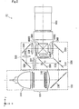
- Fig. 1 is a perspective view showing a schematic configuration of a rear projector (backproject-type display) according to an embodiment of the present invention.
- Symbols x, y, and z represent three axes orthogonal to each other.
- a rear projector 10 comprises a projection unit PJ, two projection-light reflection mirrors MR1 and MR2, and a rear screen SCR.
- a projection light-ray emitted from the projection unit PJ is reflected by the first and second projection-light reflection mirrors MR1 and MR2 to form projected images on the rear screen SCR.
- Fig. 2 is a plan view showing a schematic configuration of an optical system of the projection unit PJ. Symbols u, v, and t represent three axes orthogonal to each other.
- the projection unit PJ comprises an illumination optical system 100, a color light separation optical system 200, a relay optical system 300, three light valves 400R, 400G, and 400B, a cross-dichroic prism 500, and a projection lens 600.
- Each constituent component is arranged along a uv-plane about the cross-dichroic prism 500 as its center.
- the illumination optical system 100 comprises a light source 110, an integrator optical system 120, and an illumination-light reflection mirror 130.
- a light ray emitted from the light source 110 uniformly illuminates the light valves 400R, 400G, and 400B, which are to be illuminated, via the integrator optical system 120.
- the illumination-light reflection mirror 130 has a function to reflect an illumination-light ray emitted from the integrator optical system 120 toward the color light separation optical system 200.
- the illumination-light reflection mirror 130 may be also arranged on an optical path within the integrator optical system 120. In addition, the illumination-light reflection mirror 130 may be omitted depending on the positional arrangement of the light source 110 and the integrator optical system 120.
- a polarization-conversion optical system 140 has a function to convert a non-polarization light ray into polarized light-rays having polarization directions capable of being used in the light valves 400R, 400G, and 400B.
- the color light separation optical system 200 comprises two dichroic mirrors 210 and 220 and a reflection mirror 230, and has a function to separate illumination light emitted from the illumination optical system 100 into three color-light rays, each having a different wavelength region.
- the first dichroic mirror 210 transmits a red-light ray (R-light ray) therethrough while reflecting color-light rays having smaller wavelengths than that of the transmitted light ray (a green-light ray (G-light ray) and blue-light ray (B-light ray)).
- the R-light ray transmitted through the first dichroic mirror 210 is reflected by the reflection mirror 230 to enter the light valve 400R for the R -light ray via a field lens 240.
- the G-light ray of the G- and B-light rays reflected by the first dichroic mirror 210 is reflected by the second dichroic mirror 220 to enter the light valve 400G for the G-light ray through a field lens 250.
- the B-light ray is transmitted through the second dichroic mirror 220 to enter the light valve 400B for the B-light ray via the relay optical system 300, that is an incidence-side lens 310, a first relay reflection-mirror 320, a relay lens 330, a second relay reflection-mirror 340, and an emission-side lens 350.
- the reason for using the relay optical system 300 for the B-light ray is to prevent light utilization efficiency from being reduced by light diffusion, etc., because the optical path length of the B-light ray is larger than those of other color-light rays.
- the light valves 400R, 400G, and 400B for the respective colors modulate the respective incident color-light rays according to the corresponding color signal (image information) so as to emit the modulated light-rays as transmitted light-rays.
- a transmission-type light valve a transmission-type liquid crystal panel disposed between a pair of polarizing plates is used.
- the pair of polarizing plates may be bonded on the transmission-type liquid-crystal panel, or may be separated from the transmission-type liquid-crystal panel by being bonded on the other optical component.
- these light valves 400R, 400G, and 400B are equivalent to an electro-optical device according to the present invention, and an image represented by a modulated light-ray for each color is equivalent to an image of color component for each color constituting a color image.
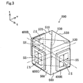
- Fig. 3 is a schematic perspective view showing the cross-dichroic prism 500 and the light valves 400R, 400G, and 400B for the respective colors.
- the cross-dichroic prism 500 is placed so that a line of intersection 530 between a first dichroic surface 510 and a second dichroic surface 520 is to be perpendicular to the uv-plane.
- first side-face i.e., an emitting surface 550
- second side-face 560 of four side-faces 550, 560, 570, and 580 are to be parallel to a ut-plane
- third and fourth side-faces 570 and 580 are to be parallel to a vt-plane.
- the second to fourth side-faces 560, 570, and 580 are provided with the light valves 400G, 400B, and 400R for the respective colors, respectively.
- These light valves 400G, 400B, and 400R are longitudinally placed so that the direction of the longer side (longer side direction) ls of a substantially rectangular image-forming region (light-illumination surface) agrees with the direction of the line of intersection 530 (intersection direction), i.e., a t-direction.
- Such an arrangement may also be referred to as a "longitudinal arrangement" below.
- the direction of the shorter side (shorter side direction) ss of the image-forming region (light-illumination surface) is arranged so as to be orthogonal to the direction of the line of intersection 530 (intersection direction), i.e., to be orthogonal to the t-direction.
- the R-light ray emitted from the light valve 400R for R-light is reflected by the first dichroic surface 510 and emitted from the emitting surface 550.
- the B-light ray emitted from the light valve 400B for B-light is reflected by the second dichroic surface 520 and emitted from the emitting surface 550.
- the G-light ray emitted from the light valve 400G for G-light is transmitted through the first and second dichroic surfaces 510 and 520, and is emitted from the emitting surface 550.
- the three-color rays modulated by the light valves 400R, 400G, and 400B for the respective colors are combined in the cross-dichroic prism 500.
- a color image represented by the combined modulated-light rays is projected by the projection lens 600.
- the color image combined in the cross-dichroic prism 500 is sidewise directed in the + u or -u direction corresponding to the longitudinal arrangement of the light valves 400R, 400G, and 400B.
- the image light representing the color image is emitted from the projection lens 600 in the + v direction.
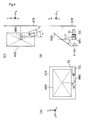
- Fig. 4 is a schematic representation for illustrating the positional relationship between the projection unit PJ, projection-light reflection mirrors MR1 and MR2, and rear Screen SCR.
- Fig. 4 (A) to Fig.(C) show a rear view, left side view, and plan view of a rear projector 10, respectively.
- the optical axial direction of image light will be described as the image-light direction below.
- the rear screen SCR is placed substantially in parallel with a yz-plane.
- the projection unit PJ is arranged so that the bottom of a casing PJC thereof is to be in parallel with an xy-plane.
- each component of the projection unit PJ shown in Fig. 2 is arranged within the casing PJC along a planar surface parallel to the bottom of the casing PJC.
- the projection unit PJ is placed so that a projection light-ray (shown by the dash-dot lines in Fig. 4 ) emitted from the projection unit PJ is incident on the first projection-light reflection mirror MR1 in parallel with the xy-plane and with an inclination of ⁇ ° with respect to a y-axis.
- a u-axis in Fig. 2 is inclined ⁇ ° with respect to an x-axis
- a v-axis in Fig. 2 is inclined ⁇ ° with respect to a y-axis.
- a t-axis in Fig. 2 is parallel to a z-axis.
- the first projection-light reflection mirror MR1 as shown in Fig. 4(A) , is placed substantially perpendicularly to the yz-plane and also with an inclination of approximate 45° relative to the xy-plane.
- ⁇ has a value more than zero and less than 90.
- the positional relationship between the first and second projection-light reflection mirrors MR1 and MR2 is that normal lines of the respective reflection surfaces are not intersected with each other so as to be in a staggered arrangement.
- a projection light-ray emitted from the projection unit PJ is reflected by the first projection-light reflection mirror MR1 to enter the second projection-light reflection mirror MR2 in parallel to the xz-plane and also with an inclination of ⁇ ° with respect to the z-axis, as shown in Fig. 4(A) and Fig. 4(B) .
- a projection light-ray reflected by the second projection-light reflection mirror MR2, as shown in Fig. 4(B) and Fig. 4(C) enters the rear screen SCR in parallel to the x-axis.
- a projection-light ray from the projection unit PJ is reflected by the first and second projection-light reflection mirrors MR1 and MR2 so as to enter the rear screen SCR.
- the two projection-light reflection mirrors MR1 and MR2 rotate an image by 90° so as to bring the direction of the longer side on the picture plane of the image projected by the projection unit PJ to agree with the direction of the longer side on the picture plane of the image projected on the rear screen. Consequently, as shown in Fig. 1 , the sidewise image indicated by the arrow is rotated so as to be the upward image indicated by the arrow by the two projection-light reflection mirrors MR1 and MR2 positioned in a staggered arrangement, and it is projected on the rear screen SCR.
- the rear projector 10 by keeping the structure that the longer side direction of the image-forming regions of the three light valves 400R, 400G, and 400B in the projection unit PJ is agreed with the direction of the line of intersection 530 of the cross-dichroic prism 500, while arranging each component of the optical system constituting the projection unit PJ along the direction of a plane (xy-plane) perpendicular to the rear screen SCR, a general sidewise image can be projected to be displayed.
- the inclination ⁇ of the second projection-light reflection mirror MR2 with respect to the yz-plane can be smaller by ( ⁇ /2)° than approximate 45°. That is, since the second projection-light reflection mirror MR2 can be raised more than 45° relative to the xy-plane, the depth from the rear screen SCR to the second projection-light reflection mirror MR2 can be reduced.
- the arrangement or positional adjustment involved in the arrangement of the optical system constituting the rear projector 10 can be facilitated, and the apparatus can be miniaturized as well.
- an image-light ray from the second projection-light reflection mirror MR2 is to be incident on the screen SCR substantially perpendicularly thereto; however, an image-light ray from the second projection-light reflection mirror MR2 may slantwise enter the screen SCR (the image-light ray is intersected with the x-axis in Fig. 4 (B) , for example).
- the present invention may also be applicable to a rear projector having such a structure. In this case, since the second projection-light reflection mirror MR2 can be raised furthermore, further reduction of the thickness of the rear projector can be achieved.
- the first projection-light reflection mirror MR1 is equivalent to a first mirror according to the present invention and the second projection-light reflection mirror MR2 is equivalent to a second mirror according to the present invention.
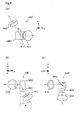
- the projection lens 600' has a structure that the first projection-light reflection mirror MR1 is arranged between a second partial lens 612 and a third partial lens 613 of three partial lenses 611, 612, and 613. Wherein a light ray incident on the projection lens 600' proceeds from the first partial lens 611 toward the third partial lens 613.
- the first projection-light reflection mirror MR1 as shown in Fig. 6(C) , is arranged substantially perpendicularly to the yz-plane and also with an inclination of approximate 45° relative to the xy-plane.
- FIG. 6(B) and Fig. 6(C) are arranged in parallel with the xy-plane and also with an inclination of ⁇ ° relative to the y-axis so as to pass through the center of the reflection surface of the first projection-light reflection mirror MR1.
- the optical axis (shown by the phantom lines in Fig. 6 ) of the third partial lens 613, as shown in Fig. 6(A) and Fig. 6(C) is arranged in parallel with the xz-plane and also with an inclination of ⁇ ° relative to the z-axis so as to pass through the center of the reflection surface of the first projection-light reflection mirror MR1.
- the projection-light reflection mirror may be preferably formed of a total reflection prism.
- reflectance of the mirror part can be increased so that bright projection images are achieved.
- first projection-light reflection mirror MR1 may also be arranged between the first and second partial lenses 611 and 612.
- the projection lens 600' has been described as having the three partial lenses; however, it is not limited to these, and various projection lenses may be used. That is, it is sufficient to arrange the first projection-light reflection mirror MR1 at any position within the projection lens.
- the first projection-light reflection mirror MR1 is not necessarily arranged within the projection lens, and it may also be integrally arranged with the projection lens on the incidence side of the first partial lens 611 or on the emission side of the third partial lens 613.
Description
- The present invention relates to a projector for projecting color images (projection display apparatus).
- As a display having a large viewing surface, projectors for magnifying and projecting images on a screen are widely used. As the projectors known are a front type projector for projecting light rays on a reflection type screen and a rear-type projector for projecting light rays on a transmission type screen. As the rear-type projector, the technique disclosed in Japanese Unexamined Patent Application Publication No.
10-307332 - In the rear-type projector, a light ray irradiated from a projecting device for projecting images is reflected by a plurality of mirrors so as to be projected on a screen. Of the plurality of mirrors, the reflecting mirror for reflecting the light ray to the screen is generally arranged to have an inclination of less than 45° with respect to the screen, and by reducing the depth from the screen to this mirror, the rear-type projector is miniaturized.
- As described above, when arranging the mirror for reflecting a light ray toward the screen, it is necessary to place the projecting device to slant relative to a plane perpendicular to the screen in order to compensate the rotation of an image to be projected on the screen. Accordingly, there is a difficulty in the positional adjustment of an optical system constituting a projector when slanting the projecting device to be placed corresponding to the inclination of the mirror.
- The present invention has been made in order to solve the above-described problem in a conventional technique, and it is an object thereof to provide a technique capable of facilitating the positional adjustment of an optical system constituting a projector and also of miniaturizing the apparatus.
- Japanese patent application published as
JP 03-083038 - According to
JP2000-075409 - In
JP 05-158151 - In order to solve at least part of the problem mentioned above, a projector according to the present invention comprises three electro-optical devices for forming images of three color components, a color-combining optical system for forming a color image by combining the images of three color components, a projection lens for projecting a color image formed by the color-combining optical system, a screen onto which the color image is projected, and first and second mirrors disposed on an optical path ranging from a plane of light incidence of the projection lens to a plane of light incidence of the screen for sequentially reflecting image light representing the color image emitted from the color-combining optical system. Furthermore, when three axes orthogonal to each other are referred to as an x-axis, a y-axis, and a z-axis, the screen is placed substantially in parallel with a yz-plane, and the color-combining optical system, having two kinds of dichroic surfaces arranged substantially in an X-shape, is placed so that a line of intersection between the two kinds of dichroic surfaces is to be substantially parallel to the z-axis. Also, each of the electro-optical devices, having a substantially rectangular image-forming region, is placed so as to face a corresponding plane of incidence out of three planes of incidence parallel to the line of intersection of the color-combining optical system so that the direction of the longer side of the image-forming region agrees with the direction of the line of intersection. Moreover, a reflection surface of the first mirror is arranged substantially perpendicularly to the yz-plane and also with an inclination of approximate 45° relative to an xy-plane, and at least the electro-optical devices, the color combining optical system, and the projection lens are arranged along the xy-plane so that an image light emitted from the color-combining optical system enters the first mirror with its optical-axis parallel to the xy-plane and inclined α° with respect to the y-axis. Also, the second mirror is placed substantially perpendicularly to an xz-plane with an inclination or substantially equal to 45-α/2° with respect to the yz-plane so that an image light reflected from the first mirror is reflected by the second mirror again so as to enter the screen with the optical axis being incident on the substantial center of the screen and substantially perpendicular to the screen.
- In the projector according to the present invention, the second mirror for reflecting image light from the first mirror to be incident on the screen can be arranged substantially perpendicularly to the xz-plane with an inclination θ substantially equal to 45-α/2° with respect to the yz-plane, so that the depth from the screen to the second mirror can be reduced. Thereby, the apparatus can be miniaturized. At least the electro-optical device, color combining system, and projection lens are arranged along a plane substantially perpendicular to the screen (horizontal plane, for example), so that the arrangement or positional adjustment involved in the arrangement of these optical components can be facilitated. Therefore, in the projector according to the present invention, the arrangement of the optical system constituting the projector can be facilitated, and the apparatus can be miniaturized as well.
- In the projector described above, the first mirror may be preferably integrally arranged with the projection lens.
- By such a structure, the arrangement space for the first mirror can be reduced, so that the apparatus can be miniaturized. In addition the meaning of "being integrally arranged" includes not only being integrally arranged combined with the vicinity of the incidence plane or the emission plane of the projection lens but also being arranged within the projection lens.
- Wherein the first mirror may be preferably formed of a total reflection prism.
- By such a structure, the reflectance of the first mirror can be increased and bright projection images can be readily achieved.
-
-
Fig. 1 is a perspective view showing a schematic structure of a rear projector according to an embodiment of the present invention. -
Fig. 2 is a plan view showing a schematic structure of an optical system of a projection unit PJ. -
Fig. 3 is a schematic perspective view showing across-dichroic prism 500 andlight valves -
Fig. 4 includes schematic illustrations showing the positional relationship between the projection unit PJ, projection-light reflection mirrors MR1 and MR2, and a rear screen SCR. -
Fig. 5 is a plan view showing a schematic structure of an optical system of a projection unit PJ' using a reflection-type liquid crystal panel as a light valve. -
Fig. 6 includes schematic illustrations showing examples of the first projection-light reflection mirror MR1 arranged within a projection lens. - Embodiments according to the present invention will be described with examples.
-
Fig. 1 is a perspective view showing a schematic configuration of a rear projector (backproject-type display) according to an embodiment of the present invention. Symbols x, y, and z represent three axes orthogonal to each other. - A rear projector 10 comprises a projection unit PJ, two projection-light reflection mirrors MR1 and MR2, and a rear screen SCR. A projection light-ray emitted from the projection unit PJ is reflected by the first and second projection-light reflection mirrors MR1 and MR2 to form projected images on the rear screen SCR.
- In addition, the positional relationship between the projection unit PJ, the first and second projection-light reflection mirrors MR1 and MR2, and the rear screen SCR will be described later.
-
Fig. 2 is a plan view showing a schematic configuration of an optical system of the projection unit PJ. Symbols u, v, and t represent three axes orthogonal to each other. The projection unit PJ comprises an illuminationoptical system 100, a color light separationoptical system 200, a relayoptical system 300, threelight valves cross-dichroic prism 500, and aprojection lens 600. - Each constituent component is arranged along a uv-plane about the
cross-dichroic prism 500 as its center. - The illumination
optical system 100 comprises alight source 110, an integratoroptical system 120, and an illumination-light reflection mirror 130. A light ray emitted from thelight source 110 uniformly illuminates thelight valves optical system 120. The illumination-light reflection mirror 130 has a function to reflect an illumination-light ray emitted from the integratoroptical system 120 toward the color light separationoptical system 200. The illumination-light reflection mirror 130 may be also arranged on an optical path within the integratoroptical system 120. In addition, the illumination-light reflection mirror 130 may be omitted depending on the positional arrangement of thelight source 110 and the integratoroptical system 120. A polarization-conversionoptical system 140 has a function to convert a non-polarization light ray into polarized light-rays having polarization directions capable of being used in thelight valves - The color light separation
optical system 200 comprises twodichroic mirrors reflection mirror 230, and has a function to separate illumination light emitted from the illuminationoptical system 100 into three color-light rays, each having a different wavelength region. - The first
dichroic mirror 210 transmits a red-light ray (R-light ray) therethrough while reflecting color-light rays having smaller wavelengths than that of the transmitted light ray (a green-light ray (G-light ray) and blue-light ray (B-light ray)). The R-light ray transmitted through the firstdichroic mirror 210 is reflected by thereflection mirror 230 to enter thelight valve 400R for the R -light ray via afield lens 240. - The G-light ray of the G- and B-light rays reflected by the first
dichroic mirror 210 is reflected by the seconddichroic mirror 220 to enter thelight valve 400G for the G-light ray through afield lens 250. On the other hand, the B-light ray is transmitted through the seconddichroic mirror 220 to enter thelight valve 400B for the B-light ray via the relayoptical system 300, that is an incidence-side lens 310, a first relay reflection-mirror 320, arelay lens 330, a second relay reflection-mirror 340, and an emission-side lens 350. The reason for using the relayoptical system 300 for the B-light ray is to prevent light utilization efficiency from being reduced by light diffusion, etc., because the optical path length of the B-light ray is larger than those of other color-light rays. - The
light valves light valves -
Fig. 3 is a schematic perspective view showing thecross-dichroic prism 500 and thelight valves cross-dichroic prism 500 is placed so that a line ofintersection 530 between a firstdichroic surface 510 and a seconddichroic surface 520 is to be perpendicular to the uv-plane. Also, it is placed so that a first side-face, i.e., an emittingsurface 550, and a second side-face 560 of four side-faces 550, 560, 570, and 580 are to be parallel to a ut-plane, and the third and fourth side-faces 570 and 580 are to be parallel to a vt-plane. The second to fourth side-faces 560, 570, and 580 are provided with thelight valves light valves - The R-light ray emitted from the
light valve 400R for R-light is reflected by the firstdichroic surface 510 and emitted from the emittingsurface 550. Also, the B-light ray emitted from thelight valve 400B for B-light is reflected by the seconddichroic surface 520 and emitted from the emittingsurface 550. Furthermore, the G-light ray emitted from thelight valve 400G for G-light is transmitted through the first and seconddichroic surfaces surface 550. Thereby, the three-color rays modulated by thelight valves cross-dichroic prism 500. A color image represented by the combined modulated-light rays is projected by theprojection lens 600. However, the color image combined in thecross-dichroic prism 500 is sidewise directed in the + u or -u direction corresponding to the longitudinal arrangement of thelight valves projection lens 600 in the + v direction. - The detailed description of the configuration and function of each component of the projector shown in
Fig. 2 is omitted in this application because they are disclosed in detail, for example, in Japanese Unexamined Patent Application Publication No.10-177151 10-186548 -
Fig. 4 is a schematic representation for illustrating the positional relationship between the projection unit PJ, projection-light reflection mirrors MR1 and MR2, and rear Screen SCR.Fig. 4 (A) to Fig.(C) show a rear view, left side view, and plan view of a rear projector 10, respectively. In addition, for facilitating description, the optical axial direction of image light will be described as the image-light direction below. - The rear screen SCR is placed substantially in parallel with a yz-plane. The projection unit PJ is arranged so that the bottom of a casing PJC thereof is to be in parallel with an xy-plane. In addition, each component of the projection unit PJ shown in
Fig. 2 is arranged within the casing PJC along a planar surface parallel to the bottom of the casing PJC. - However, the projection unit PJ, as shown in
Fig. 4 (A) and Fig. 4(C) , is placed so that a projection light-ray (shown by the dash-dot lines inFig. 4 ) emitted from the projection unit PJ is incident on the first projection-light reflection mirror MR1 in parallel with the xy-plane and with an inclination of α° with respect to a y-axis. Accordingly, a u-axis inFig. 2 is inclined α° with respect to an x-axis while a v-axis inFig. 2 is inclined α° with respect to a y-axis. In addition, a t-axis inFig. 2 is parallel to a z-axis. - The first projection-light reflection mirror MR1, as shown in
Fig. 4(A) , is placed substantially perpendicularly to the yz-plane and also with an inclination of approximate 45° relative to the xy-plane. - The second projection-light reflection mirror MR2, as shown in
Fig. 4(B) , is placed substantially perpendicularly to an xz-plane and also with an inclination of θ(= 45 - α/2)°, which is α/2° smaller than approximate 45°, with respect to the yz-plane. Where, for θ must be larger than zero, α has a value more than zero and less than 90. - In addition, the positional relationship between the first and second projection-light reflection mirrors MR1 and MR2 is that normal lines of the respective reflection surfaces are not intersected with each other so as to be in a staggered arrangement.
- A projection light-ray emitted from the projection unit PJ is reflected by the first projection-light reflection mirror MR1 to enter the second projection-light reflection mirror MR2 in parallel to the xz-plane and also with an inclination of α° with respect to the z-axis, as shown in
Fig. 4(A) and Fig. 4(B) . A projection light-ray reflected by the second projection-light reflection mirror MR2, as shown inFig. 4(B) and Fig. 4(C) , enters the rear screen SCR in parallel to the x-axis. - By the projection unit PJ and the two projection-light reflection mirrors MR1 and MR2 arranged as described above, a projection-light ray from the projection unit PJ is reflected by the first and second projection-light reflection mirrors MR1 and MR2 so as to enter the rear screen SCR.
- The two projection-light reflection mirrors MR1 and MR2 rotate an image by 90° so as to bring the direction of the longer side on the picture plane of the image projected by the projection unit PJ to agree with the direction of the longer side on the picture plane of the image projected on the rear screen. Consequently, as shown in
Fig. 1 , the sidewise image indicated by the arrow is rotated so as to be the upward image indicated by the arrow by the two projection-light reflection mirrors MR1 and MR2 positioned in a staggered arrangement, and it is projected on the rear screen SCR. - As described above, in the rear projector 10 according to the embodiment, by keeping the structure that the longer side direction of the image-forming regions of the three
light valves intersection 530 of thecross-dichroic prism 500, while arranging each component of the optical system constituting the projection unit PJ along the direction of a plane (xy-plane) perpendicular to the rear screen SCR, a general sidewise image can be projected to be displayed. - Also, in the rear projector 10 according to the embodiment, the inclination θ of the second projection-light reflection mirror MR2 with respect to the yz-plane can be smaller by (α/2)° than approximate 45°. That is, since the second projection-light reflection mirror MR2 can be raised more than 45° relative to the xy-plane, the depth from the rear screen SCR to the second projection-light reflection mirror MR2 can be reduced.
- Therefore, the arrangement or positional adjustment involved in the arrangement of the optical system constituting the rear projector 10 can be facilitated, and the apparatus can be miniaturized as well.
- Also, in the rear projector 10 according to the embodiment, an image-light ray from the second projection-light reflection mirror MR2 is to be incident on the screen SCR substantially perpendicularly thereto; however, an image-light ray from the second projection-light reflection mirror MR2 may slantwise enter the screen SCR (the image-light ray is intersected with the x-axis in
Fig. 4 (B) , for example). The present invention may also be applicable to a rear projector having such a structure. In this case, since the second projection-light reflection mirror MR2 can be raised furthermore, further reduction of the thickness of the rear projector can be achieved. - In addition, as is understood from the description above, the first projection-light reflection mirror MR1 is equivalent to a first mirror according to the present invention and the second projection-light reflection mirror MR2 is equivalent to a second mirror according to the present invention.
- In addition, the present invention is not limited to the embodiment and the examples described above; it may be carried into effect in various manners within the spirit and scope of the invention, and the following modifications may be appreciated, for example.
- (1) According to the embodiment, the projection unit PJ is described wherein a transmission-type liquid crystal panel is applied thereto as a light valve; however, a reflection-type liquid crystal panel may also be applied to the projector.
Fig. 5 is a plan view showing a schematic configuration of an optical system of a projection unit PJ' using a reflection-type liquid crystal panel as a light valve. The projection unit PJ' comprises the illuminationoptical system 100, a color light separation optical system 200', a relay optical system 300',polarization beam splitters light valves 400R', 400G', and 400B', thecross-dichroic prism 500, and theprojection lens 600. Each constituent component is arranged along the uv-plane about thecross-dichroic prism 500 as its center.
A light ray emitted from the illuminationoptical system 100 enters the color light separation optical system 200' to be separated into three color-light rays. A first dichroic mirror 210' reflects the B-light ray therefrom while reflecting color-light rays having larger wavelengths than that of the B-light ray (G-light ray and R-light ray). The R-light ray of the G- and R-light rays transmitted through the first dichroic mirror 210', is also transmitted through a second dichroic mirror 220' to enter thepolarization beam splitter 700R for the R-light ray through thefield lens 240. The G-light ray is reflected by the second dichroic mirror 220' to enter thepolarization beam splitter 700G for the G-light ray through thefield lens 250.
The B-light ray reflected by the first dichroic mirror 210' is transmitted through a relay optical system 300', that is the incidence-side lens 310, the relay reflection-mirror 320, and therelay lens 330, and furthermore through the emission-side lens 350, so as to enter thepolarization beam splitter 700B for the B-light ray.
Each of the color-light rays incident on thepolarization beam splitters separation surfaces polarization beam splitters Light valves 400R', 400G', and 400B' for the respective colors are arranged on an optical axis of one of the polarized light rays emitted from the corresponding slitter of thepolarization beam splitters separation surfaces polarization beam splitters light valves 400R', 400G', and 400B' for the respective colors are arranged on the optical axis of the S polarized light. Therefore, each color-light ray of the S polarized light enters the corresponding valve of thelight valves 400R', 400G', and 400B' as illumination light.
Thelight valves 400R', 400G', and 400B' for the respective colors modulate the polarized light incident as the illumination light according to the corresponding color signal (image information) so as to change the polarizing state and emit it. As such reflection-type light valves 400R', 400G', and 400B', reflection-type liquid crystal panels are used.
In addition, thelight valves 400R', 400G', and 400B' for the respective colors are longitudinally placed in the same way as thelight valves
A light ray emitted from each of thelight valves 400R', 400G', and 400B' for the respective colors again enters the corresponding color slitter of thepolarization beam splitters separation surfaces polarization beam splitters cross-dichroic prism 500.
Respective color light rays incident on thecross-dichroic prism 500 are combined to form a color image that is projected and displayed by theprojection lens 600. However, the color image combined by thecross-dichroic prism 500 is sidewise directed in the + u or -u direction corresponding to the longitudinal arrangement of thelight valves 400R', 400G', and 400B' for the respective colors. - (2) In general, the projection lens is formed of a group of a plurality of lenses for function sharing, and a space, in which a lens is not arranged, exists between the lenses. In consideration of this, the second projection-light reflection mirror MR2 may be integrally arranged on the incidence surface, emission surface, or inside of the
projection lens 600.Fig. 6 is a schematic representation illustrating an example that the second projection-light reflection mirror MR2 is arranged within the projection lens. - The projection lens 600' has a structure that the first projection-light reflection mirror MR1 is arranged between a second
partial lens 612 and a thirdpartial lens 613 of threepartial lenses partial lens 611 toward the thirdpartial lens 613. The first projection-light reflection mirror MR1, as shown inFig. 6(C) , is arranged substantially perpendicularly to the yz-plane and also with an inclination of approximate 45° relative to the xy-plane. The optical axes (shown by the dash-dot lines inFig. 6 ) of the first and secondpartial lenses Fig. 6(B) and Fig. 6(C) , are arranged in parallel with the xy-plane and also with an inclination of α° relative to the y-axis so as to pass through the center of the reflection surface of the first projection-light reflection mirror MR1. The optical axis (shown by the phantom lines inFig. 6 ) of the thirdpartial lens 613, as shown inFig. 6(A) and Fig. 6(C) , is arranged in parallel with the xz-plane and also with an inclination of α° relative to the z-axis so as to pass through the center of the reflection surface of the first projection-light reflection mirror MR1. - When using such a projection lens 600', since the arrangement space for the first projection-light reflection mirror MR1 can be reduced, the miniaturization of the rear projector can be furthermore achieved. In addition, when arranging the first projection-light reflection mirror MR1 within the projection lens, the projection-light reflection mirror may be preferably formed of a total reflection prism. When employing the total reflection prism, reflectance of the mirror part can be increased so that bright projection images are achieved.
- In addition, the first projection-light reflection mirror MR1 may also be arranged between the first and second
partial lenses - Also, the first projection-light reflection mirror MR1 is not necessarily arranged within the projection lens, and it may also be integrally arranged with the projection lens on the incidence side of the first
partial lens 611 or on the emission side of the thirdpartial lens 613.
Claims (3)
- A projector comprising:three electro-optical devices (400R,G,B) for forming images of three color components;a color-combining optical system (500) for forming a color image by combining the images of the three color components;a projection lens (600) for projecting the color image formed by the color-combining optical system;a screen (SCR), onto which the color image is projected; andfirst and second mirrors (MR1,MR2) disposed on an optical path ranging from a plane of incidence of the projection lens to a plane of incidence of the screen for sequentially reflecting image light representing the color image emitted from the color-combining optical system,wherein when three axes orthogonal to each other are referred to as an x-axis, a y-axis, and a z-axis, the screen is placed substantially in parallel with a yz-plane; charaterized in that :the color-combining optical system, having two kinds of dichroic surfaces arranged substantially in an X-shape, is placed so that a line of intersection between the two kinds of dichroic surfaces is to be substantially parallel to the z-axis,wherein each of the electro-optical devices, having a substantially rectangular image-forming region, is placed so as to face a corresponding plane of incidence out of three planes of incidence parallel to the line of intersection of the color-combining optical system so that the direction of the longer side of the image-forming region agrees with the direction of the line of intersection,
wherein a reflection surface of the first mirror (MR1) is arranged substantially perpendicularly to the yz-plane and also with an inclination of approximate 45° relative to an xy-plane,
wherein at least the electro-optical devices, the color combining optical system, and the projection lens are arranged along the xy-plane so that the image light emitted from the color-combining optical system enters the first mirror with its optical-axis parallel to the xy-plane and inclined α° with respect to the y-axis, and
wherein the second mirror (MR2) is placed substantially perpendicularly to an xz-plane and also with an inclination θ substantially equal to 45 - α/2° with respect to the yz-plane so that the image light reflected from the first mirror is reflected by the second mirror again so as to enter the screen with the optical axis being incident on the substantial center of the screen and substantially perpendicular to the screen. - The projector according to Claim 1, wherein the first mirror (MR1) is integrally arranged with the projection lens.
- The projector according to Claim 2, wherein the first mirror (MR1) is formed of a total reflection prism.
Applications Claiming Priority (3)
| Application Number | Priority Date | Filing Date | Title |
|---|---|---|---|
| JP2000331929A JP3900818B2 (en) | 2000-10-31 | 2000-10-31 | projector |
| JP2000331929 | 2000-10-31 | ||
| PCT/JP2001/009576 WO2002037180A1 (en) | 2000-10-31 | 2001-10-31 | Projector |
Publications (3)
| Publication Number | Publication Date |
|---|---|
| EP1280002A1 EP1280002A1 (en) | 2003-01-29 |
| EP1280002A4 EP1280002A4 (en) | 2006-12-13 |
| EP1280002B1 true EP1280002B1 (en) | 2009-04-08 |
Family
ID=18808207
Family Applications (1)
| Application Number | Title | Priority Date | Filing Date |
|---|---|---|---|
| EP01980943A Expired - Lifetime EP1280002B1 (en) | 2000-10-31 | 2001-10-31 | Projector |
Country Status (8)
| Country | Link |
|---|---|
| US (1) | US6575578B2 (en) |
| EP (1) | EP1280002B1 (en) |
| JP (1) | JP3900818B2 (en) |
| KR (2) | KR100707552B1 (en) |
| CN (1) | CN1191494C (en) |
| DE (1) | DE60138276D1 (en) |
| TW (1) | TW508475B (en) |
| WO (1) | WO2002037180A1 (en) |
Families Citing this family (10)
| Publication number | Priority date | Publication date | Assignee | Title |
|---|---|---|---|---|
| JP2003029339A (en) * | 2001-07-13 | 2003-01-29 | Minolta Co Ltd | Rear projection optical system |
| JP2004347872A (en) * | 2003-05-22 | 2004-12-09 | Fuji Photo Optical Co Ltd | Rear projection system |
| WO2005069073A1 (en) * | 2004-01-09 | 2005-07-28 | Koninklijke Philips Electronics N.V. | Image projection apparatus |
| JP2006126787A (en) * | 2004-09-30 | 2006-05-18 | Victor Co Of Japan Ltd | Image display apparatus |
| US20060077359A1 (en) * | 2004-10-10 | 2006-04-13 | Ying-Fang Lin | Projector with adjustable image offset |
| JP2006292900A (en) * | 2005-04-08 | 2006-10-26 | Hitachi Ltd | Projection optical unit and projection type image display apparatus using the same |
| US20060250587A1 (en) * | 2005-05-05 | 2006-11-09 | Regis Grasser | Image projection method and projection system |
| CN100430824C (en) * | 2005-08-04 | 2008-11-05 | 沃通加科技公司 | Projection device |
| US8042949B2 (en) * | 2008-05-02 | 2011-10-25 | Microsoft Corporation | Projection of images onto tangible user interfaces |
| CN113238438A (en) * | 2020-12-22 | 2021-08-10 | 南华智能精密机器(深圳)有限公司 | Projection module and projector |
Family Cites Families (13)
| Publication number | Priority date | Publication date | Assignee | Title |
|---|---|---|---|---|
| JPH0753338Y2 (en) * | 1986-10-29 | 1995-12-06 | 旭光学工業株式会社 | projector |
| JPH0383038A (en) * | 1989-08-28 | 1991-04-09 | Seiko Epson Corp | Rear type video projector |
| JPH05158151A (en) * | 1991-12-03 | 1993-06-25 | Seiko Epson Corp | Rear projection type display device |
| JP3285538B2 (en) | 1992-01-06 | 2002-05-27 | 三菱電機株式会社 | Projection display device |
| US5491585A (en) | 1992-11-20 | 1996-02-13 | Projectavision, Inc. | Portable rear screen television cabinet |
| JPH07219049A (en) * | 1994-02-03 | 1995-08-18 | Hitachi Ltd | Projection type display device and mirror used for the same |
| JPH0868978A (en) | 1994-08-26 | 1996-03-12 | Casio Comput Co Ltd | Liquid crystal projector |
| US5666171A (en) | 1994-08-02 | 1997-09-09 | Casio Computer Co., Ltd. | Liquid crystal image projector |
| JP3490886B2 (en) | 1998-03-03 | 2004-01-26 | シャープ株式会社 | Projection type image display device |
| JP2000122174A (en) | 1998-08-11 | 2000-04-28 | Nikon Corp | Projection type display device |
| JP2000075409A (en) * | 1998-08-31 | 2000-03-14 | Nikon Corp | Rear projection type display device |
| JP2000089360A (en) * | 1998-09-09 | 2000-03-31 | Mitsubishi Electric Corp | Projection type display device |
| JP4572425B2 (en) | 1999-01-12 | 2010-11-04 | ソニー株式会社 | Projector device and large multi-projector device using the same |
-
2000
- 2000-10-31 JP JP2000331929A patent/JP3900818B2/en not_active Expired - Fee Related
-
2001
- 2001-10-30 TW TW090126934A patent/TW508475B/en not_active IP Right Cessation
- 2001-10-31 KR KR1020057021291A patent/KR100707552B1/en not_active IP Right Cessation
- 2001-10-31 DE DE60138276T patent/DE60138276D1/en not_active Expired - Lifetime
- 2001-10-31 CN CNB018033458A patent/CN1191494C/en not_active Expired - Fee Related
- 2001-10-31 KR KR1020027008553A patent/KR20020071007A/en active Application Filing
- 2001-10-31 WO PCT/JP2001/009576 patent/WO2002037180A1/en not_active Application Discontinuation
- 2001-10-31 US US10/169,357 patent/US6575578B2/en not_active Expired - Lifetime
- 2001-10-31 EP EP01980943A patent/EP1280002B1/en not_active Expired - Lifetime
Also Published As
| Publication number | Publication date |
|---|---|
| KR100707552B1 (en) | 2007-04-13 |
| KR20020071007A (en) | 2002-09-11 |
| US6575578B2 (en) | 2003-06-10 |
| KR20050111651A (en) | 2005-11-25 |
| JP3900818B2 (en) | 2007-04-04 |
| EP1280002A1 (en) | 2003-01-29 |
| TW508475B (en) | 2002-11-01 |
| US20030058410A1 (en) | 2003-03-27 |
| CN1394295A (en) | 2003-01-29 |
| WO2002037180A1 (en) | 2002-05-10 |
| CN1191494C (en) | 2005-03-02 |
| DE60138276D1 (en) | 2009-05-20 |
| JP2002139793A (en) | 2002-05-17 |
| EP1280002A4 (en) | 2006-12-13 |
Similar Documents
| Publication | Publication Date | Title |
|---|---|---|
| US6905211B2 (en) | Color separation device, imaging optical engine, and projection apparatus | |
| JP3370010B2 (en) | LCD projector | |
| JP2001154268A (en) | Optical engine and liquid crystal projector using the same | |
| JPH11305337A (en) | Rear projection type display device | |
| US6425667B1 (en) | Projection lens unit and projector using the same | |
| JP3858723B2 (en) | Optical unit and projection type projector device using the same | |
| EP1280002B1 (en) | Projector | |
| JP2005037875A (en) | Projection type video display device | |
| JP2002182195A (en) | Projection type display | |
| EP1211546A2 (en) | Optical system of liquid crystal projector | |
| JP2002207193A (en) | Color separating/synthesizing apparatus | |
| JP2002023110A (en) | Projection system using polarizing beam splitter | |
| JP4103319B2 (en) | projector | |
| JP3642183B2 (en) | Rear projection display | |
| JP2004045907A (en) | Image display device | |
| JPH06222321A (en) | Multiplate type liquid crystal projector device | |
| JP2002090874A (en) | Optical device and projection-type display apparatus using the same | |
| JP2001051347A (en) | Rear projection type display device | |
| JPH10260474A (en) | Rear projection type display device | |
| JP3000993B2 (en) | LCD projector | |
| JP3274824B2 (en) | LCD projector | |
| JP4193385B2 (en) | projector | |
| JP2002196118A (en) | Optical element and projector | |
| JP2005292360A (en) | Projector | |
| JP3615869B2 (en) | Liquid crystal projector and projection display system using the same |
Legal Events
| Date | Code | Title | Description |
|---|---|---|---|
| PUAI | Public reference made under article 153(3) epc to a published international application that has entered the european phase |
Free format text: ORIGINAL CODE: 0009012 |
|
| 17P | Request for examination filed |
Effective date: 20021021 |
|
| AK | Designated contracting states |
Designated state(s): AT BE CH CY DE DK ES FI FR GB GR IE IT LI LU MC NL PT SE TR |
|
| RBV | Designated contracting states (corrected) |
Designated state(s): AT BE CH DE FR GB LI |
|
| A4 | Supplementary search report drawn up and despatched |
Effective date: 20061110 |
|
| 17Q | First examination report despatched |
Effective date: 20080218 |
|
| GRAP | Despatch of communication of intention to grant a patent |
Free format text: ORIGINAL CODE: EPIDOSNIGR1 |
|
| RBV | Designated contracting states (corrected) |
Designated state(s): DE FR GB |
|
| GRAS | Grant fee paid |
Free format text: ORIGINAL CODE: EPIDOSNIGR3 |
|
| GRAA | (expected) grant |
Free format text: ORIGINAL CODE: 0009210 |
|
| AK | Designated contracting states |
Kind code of ref document: B1 Designated state(s): DE FR GB |
|
| REG | Reference to a national code |
Ref country code: GB Ref legal event code: FG4D |
|
| REF | Corresponds to: |
Ref document number: 60138276 Country of ref document: DE Date of ref document: 20090520 Kind code of ref document: P |
|
| PLBE | No opposition filed within time limit |
Free format text: ORIGINAL CODE: 0009261 |
|
| STAA | Information on the status of an ep patent application or granted ep patent |
Free format text: STATUS: NO OPPOSITION FILED WITHIN TIME LIMIT |
|
| 26N | No opposition filed |
Effective date: 20100111 |
|
| REG | Reference to a national code |
Ref country code: FR Ref legal event code: PLFP Year of fee payment: 16 |
|
| PGFP | Annual fee paid to national office [announced via postgrant information from national office to epo] |
Ref country code: FR Payment date: 20160919 Year of fee payment: 16 |
|
| PGFP | Annual fee paid to national office [announced via postgrant information from national office to epo] |
Ref country code: GB Payment date: 20161026 Year of fee payment: 16 |
|
| PGFP | Annual fee paid to national office [announced via postgrant information from national office to epo] |
Ref country code: DE Payment date: 20171025 Year of fee payment: 17 |
|
| GBPC | Gb: european patent ceased through non-payment of renewal fee |
Effective date: 20171031 |
|
| REG | Reference to a national code |
Ref country code: FR Ref legal event code: ST Effective date: 20180629 |
|
| PG25 | Lapsed in a contracting state [announced via postgrant information from national office to epo] |
Ref country code: GB Free format text: LAPSE BECAUSE OF NON-PAYMENT OF DUE FEES Effective date: 20171031 |
|
| PG25 | Lapsed in a contracting state [announced via postgrant information from national office to epo] |
Ref country code: FR Free format text: LAPSE BECAUSE OF NON-PAYMENT OF DUE FEES Effective date: 20171031 |
|
| REG | Reference to a national code |
Ref country code: DE Ref legal event code: R119 Ref document number: 60138276 Country of ref document: DE |
|
| PG25 | Lapsed in a contracting state [announced via postgrant information from national office to epo] |
Ref country code: DE Free format text: LAPSE BECAUSE OF NON-PAYMENT OF DUE FEES Effective date: 20190501 |