EP1280228A2 - Large membrane space structure and method for its deployment and expansion - Google Patents
Large membrane space structure and method for its deployment and expansion Download PDFInfo
- Publication number
- EP1280228A2 EP1280228A2 EP01129966A EP01129966A EP1280228A2 EP 1280228 A2 EP1280228 A2 EP 1280228A2 EP 01129966 A EP01129966 A EP 01129966A EP 01129966 A EP01129966 A EP 01129966A EP 1280228 A2 EP1280228 A2 EP 1280228A2
- Authority
- EP
- European Patent Office
- Prior art keywords
- space structure
- structure according
- abb
- petal
- large membrane
- Prior art date
- Legal status (The legal status is an assumption and is not a legal conclusion. Google has not performed a legal analysis and makes no representation as to the accuracy of the status listed.)
- Withdrawn
Links
Images


Classifications
-
- H—ELECTRICITY
- H01—ELECTRIC ELEMENTS
- H01Q—ANTENNAS, i.e. RADIO AERIALS
- H01Q1/00—Details of, or arrangements associated with, antennas
- H01Q1/27—Adaptation for use in or on movable bodies
- H01Q1/28—Adaptation for use in or on aircraft, missiles, satellites, or balloons
- H01Q1/288—Satellite antennas
-
- H—ELECTRICITY
- H01—ELECTRIC ELEMENTS
- H01Q—ANTENNAS, i.e. RADIO AERIALS
- H01Q15/00—Devices for reflection, refraction, diffraction or polarisation of waves radiated from an antenna, e.g. quasi-optical devices
- H01Q15/14—Reflecting surfaces; Equivalent structures
- H01Q15/16—Reflecting surfaces; Equivalent structures curved in two dimensions, e.g. paraboloidal
- H01Q15/161—Collapsible reflectors
Definitions
- the present invention relates to a large membrane space structure mounted on a spacecraft or space vehicle, and a method for its deployment and expansion.
- a large membrane space structure means a large membrane structure for use in space, such as a large solar cell module used for obtaining power in space, or a solar sail or photon sail used as a propulsion system in space.
- the large membrane space structure includes a sail to which a membrane is adhered. Aluminum is sputtered onto the membrane and made specula. The sail is deployed and spanned by the centrifugal force owing to a spacecraft or an artificial satellite spin motion. As shown in FIG. 5, the sail 14 reflects solar radiation on the membrane and provides thrust F to a spacecraft or an artificial satellite by means of the reaction caused by light reflection.
- Some of the large membrane space structures of a practical scale have a rectilinear shape, each side of which may be as long as several tens of meters to a few hundred meters or longer. Accordingly, the membrane is also as large as the structure.
- the large membrane space structure travels in space where solar gravity acts. Since the light pressure acceleration that acts on the sail 14 is much smaller than the gravity of the sun or the earth, it moves mainly governed by the gravity rather than the thrust F due to the light pressure. More specifically, as shown in FIG. 6, in the solar system, even the large membrane space structure orbits like a planet around the sun. Near the earth, it may orbit around the earth as an artificial satellite.
- the thrust F generated by the sail 14 has the function of accelerating or decelerating the orbital motion, or applying acceleration to the space structure in order to change the orbit.
- the large membrane space structure starts orbital motion in space, since the acceleration and deceleration are very small, the space structure is gradually accelerated and decelerated.
- the light pressure P of the solar radiation is very low, i.e., P ⁇ 4.6 ⁇ 10 -6 N/m 2 .
- a conventional type of large membrane space structure is rectilinear.
- the large membrane space structure comprises four spars 32 to spread a sail 30.
- One end of each spar 32 is supported by a center hub 34.
- the hub 34 includes a payload and a mechanism for expanding the spars 32 (both are not shown).
- the attitude of the large membrane space structure may be controlled by the torque generated by tip vanes 36 attached to the tips of the spars 32.
- the torque may be generated by shifting the center of the pressure of the solar radiation from the mass center of the structure.
- the membrane When the sail 30 is transported into space, the membrane is folded suitably and may be wrapped around a core material such as a cylindrical pipe, so that it can be packed compactly.
- the membranes may be thought folded and wrapped after the huge sail is produced.
- the membrane itself is folded and creased, residual stress and strain may be generated and left in the membrane. To smooth out such a fold, a certain spreading force is required. Therefore, the fold is the most crucial factor that prevents the sail from being deployed in space. Otherwise, since a number of complex structures are required to deploy the sail, the deployment may even be unsuccessful.
- the sail of the large membrane space structure may require an outer frame.
- framework members such as expandable spars, are used to spread the sail. Since the framework members must be very large and stiff, the mass thereof cannot be reduced easily. Therefore, this may result in the considerably large vehicle required to transport the large membrane space structure into space.
- the present invention was devised to solve the above problems, and an object thereof is to provide a large membrane space structure and a method for its deployment and expansion.
- a large membrane space structure mounted on a spacecraft comprising:
- a large membrane space structure includes a hub 2 mounted on a spacecraft and a sail 4 having, for example, four petals 6.
- the hub 2 includes supports 8, which serve as connecting members to connect the hub 2 with the respective petals 6.
- Each support 8 includes a first support member 8a having stiffness, and a second support member 8b, which has a cord or beam structure hinged on at least a midpoint P. In this embodiment, it is assumed that the second support member 8b is beamed only at the midpoint P.
- the ends B 9 and B 9 ' of the first support member 8a are respectively connected to the ends B 8 and B 8 ' of the second support member 8b by first rigging (B 9 B 8 and B 9 'B 8 ').
- the first rigging is, for example, a long, durable hard-to-cut cord.
- Each support 8 is deflectable relative to an imaginary center line OX to be described later. It includes control means 9 for controlling the angle of deflection to a desired angle within a predetermined range.
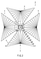
- the petals 6, having the same rectilinear shape OBAB', are spread symmetrically with respect to the center of the hub 2, as shown in FIG. 2.
- One of the apexes of the rectilinear part OBAB' that coincides with the center of hub 2 is referred to as a first fulcrum O.
- Each of the petals 6 has a shape symmetric with respect to the imaginary center line OX to be described later.
- a line passing through the first fulcrum O and the midpoint P of the second support member 8b is called an imaginary center line segment.
- a second fulcrum A is located at an end of the imaginary center line segment opposite to the first fulcrum O.
- a semi-infinite line passing through the first fulcrum O and the second fulcrum A is referred to as an imaginary center line OX.
- the petal 6 is symmetric with respect to the imaginary center line OX and comprises, for example, two triangular parts OAB and OAB'.
- the triangular parts OAB and OAB' are referred to as first regions.
- the line segments OA on the imaginary center line OX and the sides AB and AB' are, for example, 50m long.
- the triangular part ABO of the first region is divided into nine triangular parts ABB 1 , AB 1 B 2 , ⁇ AB 7 B 8 and AB 8 O by the split lines AB 1 to AB 8 .
- the parts ABB 1 , AB 1 B 2 , ⁇ and AB 7 B 8 are referred to as second regions.
- Membranes ABB 1 , AB 1 B 2 , ⁇ and AB 7 B 8 having the shapes corresponding to the triangular parts ABB 1 , AB 1 B 2 , ⁇ and AB 7 B 8 are connected to the respective second regions.
- the membranes ABB 1 , AB 1 B 2 , ⁇ and AB 7 B 8 are preferably formed of a polymeric material resistant to space environment, such as polyimide material. It is preferable that a membrane AB 8 P, formed of the polymeric material resistant to space environment and having the shape corresponding to a triangular part AB 8 P within the triangle AB 8 O, be adhered to the triangular part AB 8 P defined by the line segment OA on the imaginary center line OX, the split line AB 8 nearest to the imaginary center line and the second support member 8b. Thus, one of the apexes of each membrane is supported by the second fulcrum A. Second rigging may be extended along a side B 8 B.
- the membranes ABB 1 , AB 1 B 2 , ⁇ and AB 7 B 8 are connected to one another at the ends B 7 , B 6 , ⁇ and B 1 by bridge belts 10.
- the areal density of the membranes ABB 1 , AB 1 B 2 , ⁇ AB 7 B 8 and AB 8 P is, for example, about 30 g/m 2 or less.
- aluminum is sputtered on the membranes ABB 1 , AB 1 B 2 , ⁇ AB 7 B 8 and AB 8 P and makes them speculate. Therefore, the membranes ABB 1 , AB 1 B 2 , ⁇ AB 7 B 8 and AB 8 P reflect the solar radiation at high reflectivity.
- the mass increase due to sputtering of the membranes ABB 1 , AB 1 B 2 , ⁇ AB 7 B 8 and AB 8 P is negligible.
- the intersection between the membrane AB 7 B 8 and the second support member 8b, i.e., the point B 8 is referred to as the third fulcrum.
- the third fulcrum For example, six imaginary lines B 8 A 1 , B 8 A 2 , ⁇ and B 8 A 6 are drawn from the third fulcrum B 8 to the opposite side AB at suitable intervals.
- bridge belts 10 are arranged at the intersections between the imaginary lines B 8 A 1 , B 8 A 2 , ⁇ and B 8 A 6 and membranes ABB 1 , AB 1 B 2 , ⁇ and AB 7 B 8 , so that the adjacent members are discretely welded or adhered to each another. It is preferable that the bridge belts 10 as well as the membranes are formed of a polymeric material resistant to space environment, such as polyimide material.
- the large membrane space structure of this embodiment is very light, since it comprises almost only the membranes as described above.
- a plurality of peripheral weights can be attached to an outer side AB of the membrane ABB 1 and/or the second rigging B 8 B (peripheral portion) at suitable intervals.
- peripheral weights are attached to the outer side AB only. Details of the peripheral weights will be described later.
- membranes having the shapes corresponding to the triangular parts ABB 1 , AB 1 B 2 , ⁇ AB 7 B 8 and AB 8 P are prepared. Then, the triangle membranes are overlaid one on another so that they can be in a packing state. In this state, the membrane surfaces face each other.
- the bridge belts 10 are arranged at the predetermined positions as mentioned above and the membranes are welded and/or adhered by using the bridge belts 10.
- the bridge belts 10 are arranged such that the folds can be as small as possible. It is preferable that the bridge belts 10 have a width of several centimeters to several tens of centimeters and the length of several tens of centimeters to about one meter.
- the bridge belts 10 are sufficiently smaller than the membranes ABB 1 , AB 1 B 2 , ⁇ AB 7 B 8 and AB 8 P.
- the apexes B 8 , B 7 , ⁇ and B 1 of the membranes are connected by the bridge belts 10.
- the second rigging may be extended along the side B 8 B.
- the petal 6 is attached to the support 8.
- the apexes B, B 1 , ⁇ and B 8 of the membranes ABB 1 , AB 1 B 2 ⁇ and AB 7 B 8 are temporarily connected together.
- the connected membranes are wrapped around the hub 2 (spacecraft) and packed compactly.
- the adjacent membranes are connected by the bridge belts 10 between the membranes ABB 1 , AB 1 B 2 , ⁇ AB 7 B 8 and AB 8 P, only the belts 10 are folded and no folds are formed in the membranes themselves.
- the petal 6 can be packed upon completion of welding and/or adhesion of the bridge belts 10 to the adjacent membranes. Therefore, a small space that can contain one or two membranes is sufficient to produce and pack one petal 6.
- the petal 6 can be produced and packed more efficiently as compared to the case where all membranes are arranged at predetermined positions and adhered to one another by bridge belts 10 at predetermined positions, and the petal 6 is folded at split lines AB 1 to AB 8 and AB 1 ' to AB 8 '. Moreover, the folded petal 6 can be spread with much smaller force as compared to the case where the membranes themselves are folded and the petal 6 is spread by releasing the residual stress and strain of the folded portions of the membranes. In other words, the residual stress and strain involved in spreading the large membrane structure are limited to the width of the bridge belt 10. Therefore, the above structure is easily spread.
- the packed large membrane space structure is transported into space.
- the structure is rotated about the hub 2 at a suitable rotation speed in a direction (circumferential direction of rotation) in which the petals 6 are wrapped around the hub 2, thereby generating centrifugal force in a direction perpendicular to the circumferential direction of rotation by virtue of the function of peripheral weights.
- the petals 6 are gradually unwrapped from the hub 2 by the tension of the membranes generated in the directions of centrifugal force of the respective petals 6, and extended radially outward from the hub 2.
- the membranes ABB 1 , AB 1 B 2 , ⁇ and AB 7 B 8 are wrapped around the spacecraft, they may suffer from some warping in the longitudinal direction due to a core set. Since the core set of the membranes in the direction perpendicular to the longitudinal direction is negligible, it need not be taken into consideration.
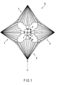
- the support 8 mounted on the hub 2 is controlled to rotate the petal 6 about the imaginary center line OX at an arbitrary angle, preferably between 45° and 60°. If the four petals 6 are spread simultaneously on the same plane as shown in FIG. 1, the adjacent petals 6 will be brought into contact with each other. To avoid this, the supports 8 are controlled by the control means 9 to rotate the petals 6, preferably at the same angle, so that the petals 6 can be substantially parallel to one another.
- the sail 4 is rotated about the first fulcrum around the hub 2 in the direction of the arrow shown in FIGS. 1, 2 and 3 at the speed of, for example, 4 rpm.
- the peripheral weights mentioned above generate centrifugal force in the radial directions perpendicular to the circumferential direction of rotation.
- the point B 8 ' symmetric to the third fulcrum B 8 with respect to the imaginary center line OX is referred to as the fourth fulcrum.
- Weak compression force which acts in the direction of closing the petal 6, may be applied across the second support members B 8 P and PB 8 '.
- the centrifugal force acting on the center of the hub 2 is virtually offset by the force acting on the third and fourth fulcrums B 8 and B 8 '.
- the peripheral weights are provided on the outer side AB.
- the weight necessary to provide force equivalent to the membrane's own weight on the earth to exert on the points A, A 1 , ⁇ , A 6 and B on the outer side AB is about 0.1 kg per meter.
- the peripheral weights of about 40 kg must be attached to the end sides. In this state, the force for spreading the petal 6 is equivalent to the force generated by suspending the petal 6 under the gravity 1G on the earth.
- the peripheral weights are not limited to the weights as described above, but can be varied in accordance with the design of the large membrane space structure.
- the bridge belts 10 connecting the membranes are located on the imaginary lines extending from the third and fourth fulcrums B 8 and B 8 ' at arbitrary angles smaller than the angle AOB. They can provide deployment force not only in the radial directions in which the centrifugal force acts but also in the circumferential direction of rotation. In other words, since imaginary angles AB 8 A 1 , A 1 B 8 A 2 , ⁇ and A 6 B 8 B are smaller than the angle AOB, deploying force for the petal 6 is exerted on the bridge belts 10 on the imaginary lines B 8 A 1 , B 8 A 2 , ⁇ and B 8 A 6 .
- the force necessary to deploy the petal 6 is the smallest at the end side AB. Therefore, if the outermost membrane ABB 1 is deployed, it is ensured that all the membranes of the petal 6 can be deployed.
- the centrifugal force by the rotation can be supplemented by the peripheral weights, and the membranes and bridge belts 10 receive not only the centrifugal force but also the deployment force in the direction perpendicular to the direction of the centrifugal force. Therefore, the force sufficient to deploy the petal 6 can be given to the petal 6.
- the peripheral weights are attached to the end side AB to deploy the large membrane space structure.
- the peripheral weights may be provided on the peripheral portion B 8 B, or no weights may be provided on the end side AB or the peripheral portion B 8 B.
- the attitude of the large membrane space structure is changed by setting its center of mass off the center of the light pressure of solar radiation.
- the large membrane space structure is rotated at a high speed, the membranes can be deployed more easily, but the amount of offset of the center of gravity, which is determined by request for change of the attitude, is increased. Therefore, it is necessary to avoid excessively high-speed rotation.
- the peripheral weights of the large membrane space structure can be lightened by increasing the rotation speed. In this case, however, a larger amount of chemical propellant is required to rotate the structure. Therefore, it is necessary to determine whether the rotation speed should be increased by using the fuel of the large membrane space structure.
- the amount of fuel required for rotation is increased in proportion to the rotation speed, while the peripheral weights can be reduced in proportion to the reciprocal of the square of the rotation speed.
- the fuel of about 40 kg is required.
- the off-center quantity necessary to change the attitude of the spacecraft by 3° a day is about 60 cm.
- the membrane density is smaller, the weight of the spacecraft in its entirety and the required amount of fuel can be less.
- the supports 8 are controlled again using the control means 9 to deflect the four petals 6 at arbitrary angles.
- a desired amount of torque is generated in accordance with the rotation angles of the petals 6 with respect to the light pressure, thereby performing attitude control and adjusting the torque of the component of the light pressure applied to the sail 4 in the circumferential direction of the rotation.
- the sides BA and AB' and the imaginary center line segment OA are about 50 m long.
- the lengths are not limited to 50 m but may be within the range of several tens to several hundreds of meters.
- the petal 6 is quadrilateral.
- the petal 6 is not limited to this shape but can be of any shape so long as it is symmetric with respect to the imaginary center line OX.
- it can be a triangle, a pentagon, or a polygon a side of which is arc-shaped (see FIG. 4).
- the petal 6 may be designed such that a point C shown in FIG. 4 is located on the imaginary center line OX. In this case, the petal 6 can be further expanded.
- the shape of the membrane is a triangle.
- it may be, for example, a rectangle or a polygon a side of which is arc-shaped (see FIG. 4).
- the petal is constituted by two polygonal parts symmetric with respect to the imaginary center line OX, as the petal 6 described above.
- One of the polygonal parts OACB has three sides CA, AO and OB and an arc BC.
- Split lines AB 8 to AB 1 , AB, and AC 6 to AC 1 are imaginarily drawn from the second fulcrum A to opposite side OB and arc BC at suitable intervals.
- Membranes are adhered to the regions defined by the side OB, the arc BC and the split lines AB 8 to AB 1 , AB, and AC 6 to AC 1 .
- imaginary lines B 8 A 1 , B 8 A 2 , B 8 C 1 to B 8 C 6 are drawn from the third fulcrum B 8 to the opposite side CA and arc BC at suitable intervals.
- Bridge belts 10 are arranged at the intersections between the imaginary lines B 8 A 1 , B 8 A 2 , B 8 C 1 to B 8 C 6 and the membranes.
- Peripheral weights (not shown) can be provided on the marginal portions AC and CB of the membranes ACC 1 , AC 1 C 2 , ⁇ AC 6 B.
- the number of petals 6 is not limited to four, so long as the petals 6 can be arranged around the hub 2 on the same plane as shown in FIGS. 1 to 3.
- first rigging B 9 B 8 and the second rigging B 8 B are separate members.
- first and second rigging B 9 B 8 and B 8 B may be formed of single rigging B 9 B as a unitary member. If a unitary member is used in place of the first and second rigging, the sides B 9 B 8 and B 8 B form a straight line. It is assumed that the intersection between the extensions of the lines BB 8 and B'B 8 is O' (not shown) in the case where the first rigging B 9 B 8 and second rigging and B 8 B are separate members. In this case, when the petal 6 is entirely deployed, the angle B 8 O'B 8 ' will be the same as or smaller than the angle B 8 OB 8 '.
- the lengths of the sides AB, AB 8 and AC shown in FIGS. 2 to 4 may be the same or different from one another.
- the petals 6 are deployed in space by rotating the sail 4 at the speed of 4 rpm.
- the rotation speed is not limited thereto. It is preferable that a rotation speed be chosen in accordance with the design of the sail 4.
- the petals 6 are not connected to one another.
- the petals may be connected to one another by, for example, rigging at some points.
- the present invention is applied to a large membrane space structure as a propulsive system.
- a solar cell module panel
- the present invention can be applied to a large solar cell membrane structure.
- the large solar cell membrane structure can be spread in the same manner as in the embodiment described above.
Abstract
Description
- The present invention relates to a large membrane space structure mounted on a spacecraft or space vehicle, and a method for its deployment and expansion.
- A large membrane space structure means a large membrane structure for use in space, such as a large solar cell module used for obtaining power in space, or a solar sail or photon sail used as a propulsion system in space.
- In recent years, there has been an increased demand for exploration of the solar system. A spacecraft such as a so-called rocket, which is propelled by a reaction of high-speed exhaust of combustion gas, can only be loaded with a limited amount of propellant or fuel. Therefore, the search for a new propulsive system that does not need propellant or fuel has been of great interest. Accordingly, the development of a large membrane space structure, such as a solar sail propelled by the reflection of solar radiation, has been strongly investigated.
- The large membrane space structure includes a sail to which a membrane is adhered. Aluminum is sputtered onto the membrane and made specula. The sail is deployed and spanned by the centrifugal force owing to a spacecraft or an artificial satellite spin motion. As shown in FIG. 5, the
sail 14 reflects solar radiation on the membrane and provides thrust F to a spacecraft or an artificial satellite by means of the reaction caused by light reflection. Some of the large membrane space structures of a practical scale have a rectilinear shape, each side of which may be as long as several tens of meters to a few hundred meters or longer. Accordingly, the membrane is also as large as the structure. - Even the large membrane space structure travels in space where solar gravity acts. Since the light pressure acceleration that acts on the
sail 14 is much smaller than the gravity of the sun or the earth, it moves mainly governed by the gravity rather than the thrust F due to the light pressure. More specifically, as shown in FIG. 6, in the solar system, even the large membrane space structure orbits like a planet around the sun. Near the earth, it may orbit around the earth as an artificial satellite. - The thrust F generated by the
sail 14 has the function of accelerating or decelerating the orbital motion, or applying acceleration to the space structure in order to change the orbit. When the large membrane space structure starts orbital motion in space, since the acceleration and deceleration are very small, the space structure is gradually accelerated and decelerated. - Referring back to FIG. 5, the thrust F on the planar large membrane space structure where area is A is represented by the following equation:


- Near the earth, the light pressure P of the solar radiation is very low, i.e., P≒4.6 × 10⁻⁶N/m2. The performance of the large membrane space structure depend on the acceleration. Assuming that the
sail 14 is formed of a membrane of an areal density of β (kg/m2), the mass is represented by βA. If β is 0.01kg/m2, the acceleration α is represented by the following equation:
- This is as substantial as the acceleration of an ion engine or a plasma engine.
- The acceleration of a large membrane space structure increases with the flight time. Therefore, the more the flight time lingers for the travel, the more advantageous the large membrane space structure is over the chemical engine consuming propellant or fuel.
- As shown in FIG. 7, a conventional type of large membrane space structure is rectilinear. The large membrane space structure comprises four
spars 32 to spread asail 30. One end of eachspar 32 is supported by acenter hub 34. Thehub 34 includes a payload and a mechanism for expanding the spars 32 (both are not shown). The attitude of the large membrane space structure may be controlled by the torque generated bytip vanes 36 attached to the tips of thespars 32. The torque may be generated by shifting the center of the pressure of the solar radiation from the mass center of the structure. - When the
sail 30 is transported into space, the membrane is folded suitably and may be wrapped around a core material such as a cylindrical pipe, so that it can be packed compactly. - To pack the large membrane space structure having rectilinear membranes, the membranes may be thought folded and wrapped after the huge sail is produced. However, it is difficult and not practical to carry out this method in the structure of practical scale.
- In addition, since the membrane itself is folded and creased, residual stress and strain may be generated and left in the membrane. To smooth out such a fold, a certain spreading force is required. Therefore, the fold is the most crucial factor that prevents the sail from being deployed in space. Otherwise, since a number of complex structures are required to deploy the sail, the deployment may even be unsuccessful.
- Moreover, the sail of the large membrane space structure may require an outer frame. For example, it is sometimes assumed that framework members, such as expandable spars, are used to spread the sail. Since the framework members must be very large and stiff, the mass thereof cannot be reduced easily. Therefore, this may result in the considerably large vehicle required to transport the large membrane space structure into space.
- Furthermore, in the large membrane space structure made of a single sail, since the amount of torque applied to the very large structure cannot be controlled easily, it is difficult to adjust the rotation speed of the spacecraft.
- The present invention was devised to solve the above problems, and an object thereof is to provide a large membrane space structure and a method for its deployment and expansion.
- To solve the above problems, according to an aspect of the present invention, there is provided a large membrane space structure mounted on a spacecraft comprising:
- a) a hub including:
- a plurality of supports, with a first imaginary fulcrum at the center of the hub, a first support member which is stiff, a second support member which is a beam structure that may be hinged on at least a midpoint thereof, and first rigging connecting ends of the first and second support members as well as the hub; and
- control means for deflecting the supports at desired angles with respect to the spacecraft by rotating them about an imaginary center line extending through the first fulcrum and the midpoint of the second support member as a pivotal member; and
- b) a sail including petals that are symmetrical with respect to the first fulcrum when deployed and attached to the supports, each petal including:
- membranes spanned on first regions symmetric with respect to the imaginary center line and including the first fulcrum, a second fulcrum located on the imaginary center line and separated from the first fulcrum, and two points symmetric with respect to the imaginary center line, the membranes spanned on second regions defined by a peripheral portion of the first region opposite to the second fulcrum and a plurality of split lines extending from the second fulcrum to the peripheral portion at arbitral intervals; and
- bridge belts along the split lines to the peripheral portion discretely connecting the membrane elements to one another at intersections between split lines and a plurality of imaginary lines extending from an end of the second support member to an end portion of an outermost membrane elements opposite to the first fulcrum, the bridge belts providing tension across the membranes.
- According to another aspect of the present invention, there is provided a method for deploying and spanning the large membrane space structure recited in claim 1, in which the petal has folds in the bridge belts, and which is folded such that adjacent membranes are faced each other, and is wrapped and packed around the hub, the method comprising:
- rotating the petal in a predetermined direction about the first supporting point;
- extending first the petal radially from the hub by centrifugal force generated in radial directions perpendicular to a direction of rotation of the petal, thereby unwrapping the membrane elements from the hub by tension generated in the radial directions while the membrane members are folded at bridge lines, and rotating the support and the petal about the imaginary center line at a desired angle; and
- unfolding the folds by tension acting on the bridge belts by the centrifugal force, and deployment force in the circumferential direction of the petal generated by both the centrifugal force and tension supporting lines extending from the end of the second support member at certain obliged angles with respect to a radial direction of the centrifugal force, thereby deploying the membrane elements.
- This summary of the invention does not necessarily describe all necessary features so that the invention may also be a sub-combination of these described features.
- The invention can be more fully understood from the following detailed description when taken in conjunction with the accompanying drawings, in which:
- FIG. 1 is a schematic diagram showing a large membrane space structure with petals of the sail half-opened according to an embodiment of the present invention;
- FIG. 2 is a schematic diagram showing an example of a large membrane space structure with petals of the sail full-opened according to an embodiment of the present invention;
- FIG. 3 is a schematic diagram showing an example of a part of a petal according to the embodiment of the present invention;
- FIG. 4 is a schematic diagram showing a modification of the petal shown in FIG. 3;
- FIG. 5 is a schematic diagram for explaining that a large membrane space structure is given thrust in a desired direction upon receipt of a light pressure by solar radiation;
- FIG. 6 is a schematic diagram showing an orbit of a spacecraft traveled by a large membrane space structure; and
- FIG. 7 is a schematic diagram showing a quadrilateral large membrane space structure according to the conventional art.
- An embodiment of the present invention will be described with reference to FIGS. 1 to 4.
- First, a structure of a large membrane space structure, which serves as a propulsion component, will be described.
- As shown in FIGS. 1 and 2, a large membrane space structure includes a
hub 2 mounted on a spacecraft and asail 4 having, for example, fourpetals 6. Thehub 2 includessupports 8, which serve as connecting members to connect thehub 2 with therespective petals 6. Eachsupport 8 includes afirst support member 8a having stiffness, and asecond support member 8b, which has a cord or beam structure hinged on at least a midpoint P. In this embodiment, it is assumed that thesecond support member 8b is beamed only at the midpoint P. The ends B9 and B9' of thefirst support member 8a are respectively connected to the ends B8 and B8' of thesecond support member 8b by first rigging (B9B8 and B9'B8'). The first rigging is, for example, a long, durable hard-to-cut cord. Eachsupport 8 is deflectable relative to an imaginary center line OX to be described later. It includes control means 9 for controlling the angle of deflection to a desired angle within a predetermined range. - The
petals 6, having the same rectilinear shape OBAB', are spread symmetrically with respect to the center of thehub 2, as shown in FIG. 2. One of the apexes of the rectilinear part OBAB' that coincides with the center ofhub 2 is referred to as a first fulcrum O. Each of thepetals 6 has a shape symmetric with respect to the imaginary center line OX to be described later. - Since the
petals 6 have the same shape and are symmetric with respect to the first fulcrum O, only onepetal 6 will be described below. - As shown in FIG. 3, a line passing through the first fulcrum O and the midpoint P of the
second support member 8b is called an imaginary center line segment. A second fulcrum A is located at an end of the imaginary center line segment opposite to the first fulcrum O. A semi-infinite line passing through the first fulcrum O and the second fulcrum A is referred to as an imaginary center line OX. As described above, thepetal 6 is symmetric with respect to the imaginary center line OX and comprises, for example, two triangular parts OAB and OAB'. The triangular parts OAB and OAB' are referred to as first regions. The line segments OA on the imaginary center line OX and the sides AB and AB' are, for example, 50m long. - For example, eight split lines AB1 to AB8 and eight split lines AB1' to AB8' are imaginarily drawn from the second fulcrum A to sides OB and OB' at appropriate intervals.
- Since the first regions ABO and AB'O are symmetric with respect to the imaginary center line OX, only one triangular part ABO of the first region will be described in the following.
- As shown in FIG. 3, the triangular part ABO of the first region is divided into nine triangular parts ABB1, AB1B2, ··· AB7B8 and AB8O by the split lines AB1 to AB8. Of the nine triangular parts, the parts ABB1, AB1B2, ··· and AB7B8 are referred to as second regions. Membranes ABB1, AB1B2, ··· and AB7B8 having the shapes corresponding to the triangular parts ABB1, AB1B2, ··· and AB7B8 are connected to the respective second regions. The membranes ABB1, AB1B2, ··· and AB7B8 are preferably formed of a polymeric material resistant to space environment, such as polyimide material. It is preferable that a membrane AB8P, formed of the polymeric material resistant to space environment and having the shape corresponding to a triangular part AB8P within the triangle AB8O, be adhered to the triangular part AB8P defined by the line segment OA on the imaginary center line OX, the split line AB8 nearest to the imaginary center line and the
second support member 8b. Thus, one of the apexes of each membrane is supported by the second fulcrum A. Second rigging may be extended along a side B8B. The membranes ABB1, AB1B2, ··· and AB7B8 are connected to one another at the ends B7, B6, ··· and B1 bybridge belts 10. - The areal density of the membranes ABB1, AB1B2, ··· AB7B8 and AB8P is, for example, about 30 g/m2 or less. For example, aluminum is sputtered on the membranes ABB1, AB1B2, ··· AB7B8 and AB8P and makes them speculate. Therefore, the membranes ABB1, AB1B2, ··· AB7B8 and AB8P reflect the solar radiation at high reflectivity. The mass increase due to sputtering of the membranes ABB1, AB1B2, ··· AB7B8 and AB8P is negligible.
- The intersection between the membrane AB7B8 and the
second support member 8b, i.e., the point B8 is referred to as the third fulcrum. For example, six imaginary lines B8A1, B8A2, ··· and B8A6 are drawn from the third fulcrum B8 to the opposite side AB at suitable intervals. - As shown in FIG. 3,
bridge belts 10 are arranged at the intersections between the imaginary lines B8A1, B8A2, ··· and B8A6 and membranes ABB1, AB1B2, ··· and AB7B8, so that the adjacent members are discretely welded or adhered to each another. It is preferable that thebridge belts 10 as well as the membranes are formed of a polymeric material resistant to space environment, such as polyimide material. - The large membrane space structure of this embodiment is very light, since it comprises almost only the membranes as described above.
- A plurality of peripheral weights (not shown) can be attached to an outer side AB of the membrane ABB1 and/or the second rigging B8B (peripheral portion) at suitable intervals. In the following description, it is assumed that peripheral weights are attached to the outer side AB only. Details of the peripheral weights will be described later.
- A process of producing and packing the aforementioned large membrane space structure will be described.
- First, membranes having the shapes corresponding to the triangular parts ABB1, AB1B2, ··· AB7B8 and AB8P are prepared. Then, the triangle membranes are overlaid one on another so that they can be in a packing state. In this state, the membrane surfaces face each other. The
bridge belts 10 are arranged at the predetermined positions as mentioned above and the membranes are welded and/or adhered by using thebridge belts 10. Preferably, thebridge belts 10 are arranged such that the folds can be as small as possible. It is preferable that thebridge belts 10 have a width of several centimeters to several tens of centimeters and the length of several tens of centimeters to about one meter. Thus, thebridge belts 10 are sufficiently smaller than the membranes ABB1, AB1B2, ··· AB7B8 and AB8P. The apexes B8, B7, ··· and B1 of the membranes are connected by thebridge belts 10. As described before, the second rigging may be extended along the side B8B. Thepetal 6 is attached to thesupport 8. - The apexes B, B1, ··· and B8 of the membranes ABB1, AB1B2 ··· and AB7B8 are temporarily connected together. The connected membranes are wrapped around the hub 2 (spacecraft) and packed compactly.
- Thus, the adjacent membranes are connected by the
bridge belts 10 between the membranes ABB1, AB1B2, ··· AB7B8 and AB8P, only thebelts 10 are folded and no folds are formed in the membranes themselves. In addition, since the membranes are overlaid one on another, thepetal 6 can be packed upon completion of welding and/or adhesion of thebridge belts 10 to the adjacent membranes. Therefore, a small space that can contain one or two membranes is sufficient to produce and pack onepetal 6. In other words, thepetal 6 can be produced and packed more efficiently as compared to the case where all membranes are arranged at predetermined positions and adhered to one another bybridge belts 10 at predetermined positions, and thepetal 6 is folded at split lines AB1 to AB8 and AB1' to AB8'. Moreover, the foldedpetal 6 can be spread with much smaller force as compared to the case where the membranes themselves are folded and thepetal 6 is spread by releasing the residual stress and strain of the folded portions of the membranes. In other words, the residual stress and strain involved in spreading the large membrane structure are limited to the width of thebridge belt 10. Therefore, the above structure is easily spread. - A process of deployment (and expansion) spreading the large membrane space structure in space will now be described.
- First, the packed large membrane space structure is transported into space. The structure is rotated about the
hub 2 at a suitable rotation speed in a direction (circumferential direction of rotation) in which thepetals 6 are wrapped around thehub 2, thereby generating centrifugal force in a direction perpendicular to the circumferential direction of rotation by virtue of the function of peripheral weights. Thepetals 6 are gradually unwrapped from thehub 2 by the tension of the membranes generated in the directions of centrifugal force of therespective petals 6, and extended radially outward from thehub 2. - The temporary connection of the apexes B, B1, ··· and B8 of the membranes ABB1, AB1B2 ··· and AB7B8 are released.
- Since the membranes ABB1, AB1B2, ··· and AB7B8 are wrapped around the spacecraft, they may suffer from some warping in the longitudinal direction due to a core set. Since the core set of the membranes in the direction perpendicular to the longitudinal direction is negligible, it need not be taken into consideration.
- When the
petals 6 are rotated and spread, around thebridge belts 10 connecting the outermost membrane ABB1 and the adjacent membrane AB1B2, the centrifugal force acting in the radial direction, in which thepetal 6 is spread, balances the force acting in the circumferential direction of rotation. Therefore, the centrifugal force due to the rotation gives tension across the membranes and thebridge belts 10. The tension acts in the direction in which the residual stress and strain of the folds of thebridge belts 10 connecting the membranes and the core set in the membranes are released. - Then, the
support 8 mounted on thehub 2 is controlled to rotate thepetal 6 about the imaginary center line OX at an arbitrary angle, preferably between 45° and 60°. If the fourpetals 6 are spread simultaneously on the same plane as shown in FIG. 1, theadjacent petals 6 will be brought into contact with each other. To avoid this, thesupports 8 are controlled by the control means 9 to rotate thepetals 6, preferably at the same angle, so that thepetals 6 can be substantially parallel to one another. - Thereafter, the
sail 4 is rotated about the first fulcrum around thehub 2 in the direction of the arrow shown in FIGS. 1, 2 and 3 at the speed of, for example, 4 rpm. The peripheral weights mentioned above generate centrifugal force in the radial directions perpendicular to the circumferential direction of rotation. The point B8' symmetric to the third fulcrum B8 with respect to the imaginary center line OX is referred to as the fourth fulcrum. - Weak compression force, which acts in the direction of closing the
petal 6, may be applied across the second support members B8P and PB8'. When thepetal 6 is rotated, the centrifugal force acting on the center of thehub 2 is virtually offset by the force acting on the third and fourth fulcrums B8 and B8'. Therefore, deploying force of the membranes is applied also in the circumferential direction of rotation by tension supporting lines, namely the imaginary lines B8A1, B8A2, ··· and B8A6 (B8'A1', B8'A2', ··· and B8'A6') extending from the third fulcrum B8 (the fourth fulcrum B8') at angles with respect to the radial directions. Thus, thepetal 6 can be deployed. - As described before, the peripheral weights are provided on the outer side AB. In the case where the rotation speed of the spacecraft is 4 rpm and the distance between the points O and A is about 50 m, the weight necessary to provide force equivalent to the membrane's own weight on the earth to exert on the points A, A1, ···, A6 and B on the outer side AB is about 0.1 kg per meter. Accordingly, in the case where the end side AB of the
sail 4 is about 50 m, since the total length of all end sides is about 400 m, the peripheral weights of about 40 kg must be attached to the end sides. In this state, the force for spreading thepetal 6 is equivalent to the force generated by suspending thepetal 6 under the gravity 1G on the earth. The peripheral weights are not limited to the weights as described above, but can be varied in accordance with the design of the large membrane space structure. - The
bridge belts 10 connecting the membranes are located on the imaginary lines extending from the third and fourth fulcrums B8 and B8' at arbitrary angles smaller than the angle AOB. They can provide deployment force not only in the radial directions in which the centrifugal force acts but also in the circumferential direction of rotation. In other words, since imaginary angles AB8A1, A1B8A2, ··· and A6B8B are smaller than the angle AOB, deploying force for thepetal 6 is exerted on thebridge belts 10 on the imaginary lines B8A1, B8A2, ··· and B8A6. - The force necessary to deploy the
petal 6 is the smallest at the end side AB. Therefore, if the outermost membrane ABB1 is deployed, it is ensured that all the membranes of thepetal 6 can be deployed. - Since the rotation speed of the sail is gradually reduced as the
petal 6 is deployed, thepetals 6 is deployed passively. - Thus, the centrifugal force by the rotation can be supplemented by the peripheral weights, and the membranes and
bridge belts 10 receive not only the centrifugal force but also the deployment force in the direction perpendicular to the direction of the centrifugal force. Therefore, the force sufficient to deploy thepetal 6 can be given to thepetal 6. - In this embodiment, the peripheral weights are attached to the end side AB to deploy the large membrane space structure. However, depending on the design of the structure or the density of the membrane, the peripheral weights may be provided on the peripheral portion B8B, or no weights may be provided on the end side AB or the peripheral portion B8B.
- The attitude of the large membrane space structure is changed by setting its center of mass off the center of the light pressure of solar radiation. When the large membrane space structure is rotated at a high speed, the membranes can be deployed more easily, but the amount of offset of the center of gravity, which is determined by request for change of the attitude, is increased. Therefore, it is necessary to avoid excessively high-speed rotation.
- The peripheral weights of the large membrane space structure can be lightened by increasing the rotation speed. In this case, however, a larger amount of chemical propellant is required to rotate the structure. Therefore, it is necessary to determine whether the rotation speed should be increased by using the fuel of the large membrane space structure. The amount of fuel required for rotation is increased in proportion to the rotation speed, while the peripheral weights can be reduced in proportion to the reciprocal of the square of the rotation speed.
- For example, in the case of a bipropellant system using hydrazine and nitrogen tetroxide, to increase the rotation speed of the spacecraft having a mass of about 500 kg from 0 rpm to 4 rpm, if the density of the membrane is about 30 g/m2 or less and sides BA and AB' and the line segment OA on the imaginary center line OX of the
sail 4 are about 50 m, the fuel of about 40 kg is required. Thus, a large part of the fuel loaded in the spacecraft may be used to increase the rotation speed. The off-center quantity necessary to change the attitude of the spacecraft by 3° a day is about 60 cm. Naturally, if the membrane density is smaller, the weight of the spacecraft in its entirety and the required amount of fuel can be less. - After the
petal 6 is spread, thesupports 8 are controlled again using the control means 9 to deflect the fourpetals 6 at arbitrary angles. A desired amount of torque is generated in accordance with the rotation angles of thepetals 6 with respect to the light pressure, thereby performing attitude control and adjusting the torque of the component of the light pressure applied to thesail 4 in the circumferential direction of the rotation. - In this embodiment, the sides BA and AB' and the imaginary center line segment OA are about 50 m long. However, the lengths are not limited to 50 m but may be within the range of several tens to several hundreds of meters.
- Further, in this embodiment, the
petal 6 is quadrilateral. However, thepetal 6 is not limited to this shape but can be of any shape so long as it is symmetric with respect to the imaginary center line OX. For example, it can be a triangle, a pentagon, or a polygon a side of which is arc-shaped (see FIG. 4). Furthermore, thepetal 6 may be designed such that a point C shown in FIG. 4 is located on the imaginary center line OX. In this case, thepetal 6 can be further expanded. - Moreover, according to this embodiment, the shape of the membrane (the second region) is a triangle. However, it may be, for example, a rectangle or a polygon a side of which is arc-shaped (see FIG. 4).
- A modification of the petal shape will now be described with reference to FIG. 4. The petal is constituted by two polygonal parts symmetric with respect to the imaginary center line OX, as the
petal 6 described above. One of the polygonal parts OACB has three sides CA, AO and OB and an arc BC. Split lines AB8 to AB1, AB, and AC6 to AC1 are imaginarily drawn from the second fulcrum A to opposite side OB and arc BC at suitable intervals. Membranes are adhered to the regions defined by the side OB, the arc BC and the split lines AB8 to AB1, AB, and AC6 to AC1. - Further, imaginary lines B8A1, B8A2, B8C1 to B8C6 are drawn from the third fulcrum B8 to the opposite side CA and arc BC at suitable intervals.
Bridge belts 10 are arranged at the intersections between the imaginary lines B8A1, B8A2, B8C1 to B8C6 and the membranes. - Peripheral weights (not shown) can be provided on the marginal portions AC and CB of the membranes ACC1, AC1C2, ··· AC6B.
- According to the embodiment, the number of
petals 6 is not limited to four, so long as thepetals 6 can be arranged around thehub 2 on the same plane as shown in FIGS. 1 to 3. - Further, in the above embodiment, the first rigging B9B8 and the second rigging B8B are separate members. However, the first and second rigging B9B8 and B8B may be formed of single rigging B9B as a unitary member. If a unitary member is used in place of the first and second rigging, the sides B9B8 and B8B form a straight line. It is assumed that the intersection between the extensions of the lines BB8 and B'B8 is O' (not shown) in the case where the first rigging B9B8 and second rigging and B8B are separate members. In this case, when the
petal 6 is entirely deployed, the angle B8O'B8' will be the same as or smaller than the angle B8OB8'. - In this embodiment, the lengths of the sides AB, AB8 and AC shown in FIGS. 2 to 4 may be the same or different from one another.
- In the embodiment, the
petals 6 are deployed in space by rotating thesail 4 at the speed of 4 rpm. However, the rotation speed is not limited thereto. It is preferable that a rotation speed be chosen in accordance with the design of thesail 4. - According to the embodiment, the
petals 6 are not connected to one another. However, the petals may be connected to one another by, for example, rigging at some points. - In the above embodiment, the present invention is applied to a large membrane space structure as a propulsive system. However, if a solar cell module (panel) is used in place of the membrane, the present invention can be applied to a large solar cell membrane structure. The large solar cell membrane structure can be spread in the same manner as in the embodiment described above.
Claims (20)
- A large membrane space structure mounted on a spacecraft characterized by comprising:a) a hub (2) including:a plurality of supports (8), with a first imaginary fulcrum (O) at the center of the hub (2), a first support member (8a) which is stiff, a second support member (8b) which is a beam structure that may be hinged on at least a midpoint (P) thereof, and first rigging (B9B8 and B9'B8') connecting ends (B9 and B9'; B8 and B8') of the first and second support members (8a, 8b) as well as the hub (2); andcontrol means (9) for deflecting the supports (8) at desired angles with respect to the spacecraft by rotating them about an imaginary center line (OX) extending through the first fulcrum (O) and the midpoint (P) of the second support member (8b) as a pivotal member; andb) a sail (4) including petals (6) that are symmetrical with respect to the first fulcrum (O) when deployed and attached to the supports (8), each petal including:membranes (ABB1, AB1B2, ···, AB7B8; AB'B1', AB1'B2', ···, AB7'B8') spanned on first regions (OAB; OAB') symmetric with respect to the imaginary center line (OX) and including the first fulcrum (O), a second fulcrum (A) located on the imaginary center line (OX) and separated from the first fulcrum (O), and two points (B; B') symmetric with respect to the imaginary center line (OX), the membranes spanned on second regions (ABB1, AB1B2, ···, AB7B8; AB'B1', AB1'/B2', ···, AB7'B8') defined by a peripheral portion (B8B; B8'B') of the first region (OAB; OAB') opposite to the second fulcrum (A) and a plurality of split lines (AB1, AB2, ···, AB8; AB1', AB2', ···, AB8') extending from the second fulcrum (A) to the peripheral portion (B8B; B8'B') at arbitral intervals; andbridge belts (10) along the split lines to the peripheral portion (B8B; B8'B') discretely connecting the membrane elements (ABB1, AB1B2, ···, AB7B8; AB'B1', AB1'B2', ···, AB7'B8') to one another at intersections between split lines and a plurality of imaginary lines (B8A1 to B8A6; B8'A1' to B8'A6') extending from an end (B8; B8') of the second support member (8b) to an end portion (AB; AB') of an outermost membrane elements (ABB1; AB'B1') opposite to the first fulcrum (O), the bridge belts (10) providing tension across the membranes.
- A large membrane space structure according to claim 1, characterized by further comprising membranes (AB8P; AB8'P) spanned on regions defined by the imaginary center line (OX) and the split lines (AB8; AB8') nearest to the imaginary center line (OX).
- A large membrane space structure according to claim 2, characterized in that the bridge belts (10) are welded and adhered at predetermined positions between the membrane elements (ABB1, AB1B2, ···, AB7B8 and AB8P; AB'B1', AB1'B2', ···, AB7'B8' and AB8'P).
- A large membrane space structure according to claim 2, characterized in that the bridge belts (10) are welded to predetermined positions between the membrane elements (ABB1, AB1B2, ···, AB7B8 and AB8P; ABB1', AB1'B2', ···, AB7'B8' and AB8'P).
- A large membrane space structure according to claim 2, characterized in that the bridge belts (10) are adhered at predetermined positions between the membrane elements (ABB1, AB1B2, ···, AB7B8 and AB8P; AB'B1', AB1'B2', ···, AB7'B8' and AB8'P).
- A large membrane space structure according to claim 2, characterized in that the membrane elements (ABB1, AB1B2, ···, AB7B8 and AB8P; AB'B1', AB1'B2', ···, AB7'B8' and AB8'P) and the bridge belts (10) are formed of a polymeric material resistant to space environment.
- A large membrane space structure according to claim 6, characterized in that the membranes and the bridge belts have specula surfaces.
- A large membrane space structure according to claim 6, characterized in that the membranes have specula surfaces.
- A large membrane space structure according to claim 6, characterized in that the bridge belts have specula surfaces.
- A large membrane space structure according to claim 2, characterized in that the membrane elements (ABB1, AB1B2, ···, AB7B8 and AB8P) are equipped with solar cell modules.
- A large membrane space structure according to claim 2, characterized in that the petal (6) has folds in the bridge belts (10) and is folded such that adjacent membrane elements (ABB1, AB1B2, ···, AB7B8 and AB8P; AB'B1', AB1'B2', ···, AB7'B8' and AB8'P) are faced each other.
- A large membrane space structure according to claim 11, characterized in that the petal (6) is wrapped and packed around the hub (2).
- A large membrane space structure according to claim 1, characterized in that second rigging (B8B; B8'B') extending from the first fulcrum (O) and forming the peripheral portion (B8B; B8'B').
- A large membrane space structure according to claim 13, characterized in that the petals (6) are connected to each other on the second rigging (B8B; B8'B').
- A large membrane space structure according to claim 13, characterized in that the first rigging (B9B8; B9'B8') and the second rigging (B8B; B8'B') are integrally formed as a unitary member.
- A large membrane space structure according to claim 1, characterized in that the peripheral portion (B8B; B8'B') and the end portion (AB; AB') are equipped with peripheral weights that assist the deployment.
- A large membrane space structure according to claim 1, characterized in that the peripheral portion (B8B; B8'B') is equipped with peripheral weights that assist the deployment.
- A large membrane space structure according to claim 1, characterized in that the end portion (AB; AB') is equipped with peripheral weights.
- A method for deploying the large membrane space structure recited in claim 1, characterized in that the petal (6) has folds at the bridge belts (10), and which is folded such that adjacent membrane elements (ABB1, AB1B2, ··· and AB7B8; AB'B1', AB1'B2', ··· and AB7'B8') are faced each other, and is wrapped and packed around the hub (2), said method comprising:rotating the petal (6) in a predetermined direction about the first supporting point (O);extending first the petal (6) radially from the hub (2) by centrifugal force generated in radial directions perpendicular to a direction of rotation of the petal (6), thereby unwrapping the membrane elements (ABB1, AB1B2, ··· and AB7B8) from the hub (2) by tension generated in the radial directions while the membrane members are folded at bridge lines, and rotating the support (8) and the petal (6) about the imaginary center line (OX) at a desired angle; andunfolding the folds by tension acting on the bridge belts (10) by the centrifugal force, and deployment force in the circumferential direction of the petal (6) generated by both the centrifugal force and tension supporting lines extending from the end (B8; B8') of the second support member (8b) at certain obliged angles with respect to a radial direction of the centrifugal force, thereby deploying the membrane elements (ABB1, AB1B2, ··· and AB7B8; AB'B1', KB1'B2', ··· and AB7'B8').
- A method for deploying the large membrane space structure according to claim 19, characterized by further comprising tilting the support (8) and the petal (6) about the imaginary center line (OX), thereby controlling an amount of torque generated in the petal (6).
Applications Claiming Priority (2)
| Application Number | Priority Date | Filing Date | Title |
|---|---|---|---|
| JP2001215823A JP3541225B2 (en) | 2001-07-16 | 2001-07-16 | Large membrane space structure and deployment method thereof |
| JP2001215823 | 2001-07-16 |
Publications (2)
| Publication Number | Publication Date |
|---|---|
| EP1280228A2 true EP1280228A2 (en) | 2003-01-29 |
| EP1280228A3 EP1280228A3 (en) | 2003-09-17 |
Family
ID=19050388
Family Applications (1)
| Application Number | Title | Priority Date | Filing Date |
|---|---|---|---|
| EP01129966A Withdrawn EP1280228A3 (en) | 2001-07-16 | 2001-12-17 | Large membrane space structure and method for its deployment and expansion |
Country Status (5)
| Country | Link |
|---|---|
| US (1) | US6689952B2 (en) |
| EP (1) | EP1280228A3 (en) |
| JP (1) | JP3541225B2 (en) |
| CA (1) | CA2367979C (en) |
| RU (1) | RU2232111C2 (en) |
Cited By (3)
| Publication number | Priority date | Publication date | Assignee | Title |
|---|---|---|---|---|
| GB2434345A (en) * | 2005-12-28 | 2007-07-25 | Frank Ellinghaus | Solar sail arrangement |
| CN105539879A (en) * | 2015-12-02 | 2016-05-04 | 上海宇航系统工程研究所 | Spatial box type cabin structure |
| CN111591471A (en) * | 2020-04-30 | 2020-08-28 | 南京理工大学 | Braking sail derailing device applied to standing satellite |
Families Citing this family (34)
| Publication number | Priority date | Publication date | Assignee | Title |
|---|---|---|---|---|
| WO2004098994A2 (en) * | 2002-12-13 | 2004-11-18 | Arizona Board Of Regents | Attitude determination and control system for a solar sail spacecraft |
| US20040216770A1 (en) * | 2003-04-29 | 2004-11-04 | Taiwan Semiconductor Manufacturing Co., Ltd. | Process for rinsing and drying substrates |
| JP2005268664A (en) * | 2004-03-19 | 2005-09-29 | Fujimi Inc | Abrasive composition |
| US20050274849A1 (en) * | 2004-06-10 | 2005-12-15 | Klosner Mark A | Highly-integrated low-mass solar sail |
| US20070276354A1 (en) * | 2004-07-21 | 2007-11-29 | Cook Incorporated | Introducer Sheath and Method for Making |
| US7469864B2 (en) * | 2006-02-28 | 2008-12-30 | Bigelow Aerospace | Method for assemblying and landing a habitable structure on an extraterrestrial body |
| US7641151B2 (en) * | 2006-03-02 | 2010-01-05 | Pekka Janhunen | Electric sail for producing spacecraft propulsion |
| US9214892B2 (en) * | 2007-11-21 | 2015-12-15 | Orbital Atk, Inc. | Solar arrays |
| US9352853B2 (en) | 2007-11-21 | 2016-05-31 | Orbital Atk, Inc. | Solar arrays, deployment mechanisms therefor, and related methods |
| US8356774B1 (en) | 2008-04-21 | 2013-01-22 | The United States Of America As Represented By The Secretary Of The Air Force | Structure for storing and unfurling a flexible material |
| US8122646B1 (en) | 2009-03-12 | 2012-02-28 | The United States Of America As Represented By The Administrator Of The National Aeronautics And Space Administration | Method and apparatus for an inflatable shell |
| US8905357B1 (en) * | 2009-10-02 | 2014-12-09 | MMA Design, LLC | Thin membrane structure |
| US9550584B1 (en) * | 2010-09-30 | 2017-01-24 | MMA Design, LLC | Deployable thin membrane apparatus |
| RU2463221C1 (en) * | 2011-02-21 | 2012-10-10 | Открытое акционерное общество "Военно-промышленная корпорация "Научно-производственное объединение машиностроения" | Method for active-passive damping, orientation and stabilisation of spacecraft |
| US8646747B1 (en) * | 2011-07-11 | 2014-02-11 | Intellectual Ventures Fund 79 Llc | Methods, devices, and mediums associated with optical lift mechanism |
| WO2015179214A2 (en) | 2014-05-14 | 2015-11-26 | California Institute Of Technology | Large-scale space-based solar power station: power transmission using steerable beams |
| WO2015179213A2 (en) | 2014-05-14 | 2015-11-26 | California Institute Of Technology | Large-scale space-based solar power station: multi-scale modular space power |
| EP3149777B1 (en) | 2014-06-02 | 2024-02-14 | California Institute of Technology | Large-scale space-based solar power station: efficient power generation tiles |
| JP6337673B2 (en) * | 2014-07-28 | 2018-06-06 | 日本電気株式会社 | Solar sail and solar sail spacecraft using the same |
| EP3325347B1 (en) | 2015-07-22 | 2021-06-16 | California Institute of Technology | Large-area structures for compact packaging |
| US10992253B2 (en) | 2015-08-10 | 2021-04-27 | California Institute Of Technology | Compactable power generation arrays |
| EP3334655B1 (en) | 2015-08-10 | 2021-03-24 | California Institute of Technology | Systems and methods for performing shape estimation using sun sensors in large-scale space-based solar power stations |
| WO2017193091A1 (en) | 2016-05-05 | 2017-11-09 | L'garde, Inc. | Solar sail for orbital maneuvers |
| CN106428635B (en) * | 2016-10-14 | 2019-05-07 | 南京理工大学 | A kind of Solar sail spacecraft three-axis attitude control executing agency |
| CN107416232B (en) * | 2017-07-19 | 2023-05-16 | 浙江理工大学 | Parabolic petal type folding and unfolding device |
| WO2019210286A1 (en) * | 2018-04-27 | 2019-10-31 | Roccor, Llc | Furlable sail devices, systems, and methods |
| US11634240B2 (en) | 2018-07-17 | 2023-04-25 | California Institute Of Technology | Coilable thin-walled longerons and coilable structures implementing longerons and methods for their manufacture and coiling |
| US11772826B2 (en) | 2018-10-31 | 2023-10-03 | California Institute Of Technology | Actively controlled spacecraft deployment mechanism |
| CN109782787B (en) * | 2019-03-08 | 2020-10-30 | 北京航空航天大学 | Dual-mode MPC control method for attitude of under-actuated spacecraft under assistance of sunlight pressure |
| EP3962815B1 (en) * | 2019-05-02 | 2024-02-21 | L'garde, Inc. | Solar sail attachment and deployment methods |
| CN110615124B (en) * | 2019-09-29 | 2022-05-03 | 南京航空航天大学 | Wound form space capture device |
| CN112977896B (en) * | 2021-02-03 | 2022-04-08 | 南京航空航天大学 | Multi-micro-nano satellite rapid deployment structure for non-cooperative target in-orbit service |
| USD947761S1 (en) | 2021-03-13 | 2022-04-05 | Leala Nakagawa | Retractable structural template |
| CN114162351A (en) * | 2021-12-31 | 2022-03-11 | 中国航天空气动力技术研究院 | Pod-shaped supporting rod device |
Citations (1)
| Publication number | Priority date | Publication date | Assignee | Title |
|---|---|---|---|---|
| US5642122A (en) * | 1991-11-08 | 1997-06-24 | Teledesic Corporation | Spacecraft antennas and beam steering methods for satellite communciation system |
Family Cites Families (7)
| Publication number | Priority date | Publication date | Assignee | Title |
|---|---|---|---|---|
| US4614319A (en) * | 1980-05-05 | 1986-09-30 | Drexler Kim E | Solar sail |
| JPH01275300A (en) * | 1988-04-28 | 1989-11-02 | Nec Corp | Spacecraft attitude control method using solar radiation pressure |
| WO1990006259A1 (en) * | 1988-12-02 | 1990-06-14 | Institut Kosmicheskikh Issledovany Akademii Nauk Sssr | Space apparatus |
| RU1758988C (en) | 1989-11-16 | 1995-08-20 | Головное конструкторское бюро Научно-производственного объединения "Энергия" | Space vehicle with solar sail |
| US5296044A (en) * | 1992-03-06 | 1994-03-22 | Aec-Able Engineering Company, Inc. | Lightweight stowable and deployable solar cell array |
| RU2053941C1 (en) | 1993-04-12 | 1996-02-10 | Александр Владимирович Лукьянов | Space vehicle with solar sail |
| US6194790B1 (en) * | 1999-11-22 | 2001-02-27 | The United States Of America As Represented By The Secretary Of The Air Force | Solar sail for power generation |
-
2001
- 2001-07-16 JP JP2001215823A patent/JP3541225B2/en not_active Expired - Lifetime
- 2001-12-14 US US10/014,346 patent/US6689952B2/en not_active Expired - Fee Related
- 2001-12-17 EP EP01129966A patent/EP1280228A3/en not_active Withdrawn
-
2002
- 2002-01-09 RU RU2002101323/11A patent/RU2232111C2/en not_active IP Right Cessation
- 2002-01-14 CA CA002367979A patent/CA2367979C/en not_active Expired - Fee Related
Patent Citations (1)
| Publication number | Priority date | Publication date | Assignee | Title |
|---|---|---|---|---|
| US5642122A (en) * | 1991-11-08 | 1997-06-24 | Teledesic Corporation | Spacecraft antennas and beam steering methods for satellite communciation system |
Non-Patent Citations (1)
| Title |
|---|
| GARNER C E: "Large area sail design concepts" JPL, vol. 7, 18 March 2000 (2000-03-18), pages 447-457, XP010517976 * |
Cited By (4)
| Publication number | Priority date | Publication date | Assignee | Title |
|---|---|---|---|---|
| GB2434345A (en) * | 2005-12-28 | 2007-07-25 | Frank Ellinghaus | Solar sail arrangement |
| GB2434345B (en) * | 2005-12-28 | 2008-04-09 | Frank Ellinghaus | Solar-sail-launch-system, comprising a launch vehicle and a solar sail mothership spacecraft with "roller-reefing"-ACS and solar electric propulsion. |
| CN105539879A (en) * | 2015-12-02 | 2016-05-04 | 上海宇航系统工程研究所 | Spatial box type cabin structure |
| CN111591471A (en) * | 2020-04-30 | 2020-08-28 | 南京理工大学 | Braking sail derailing device applied to standing satellite |
Also Published As
| Publication number | Publication date |
|---|---|
| US6689952B2 (en) | 2004-02-10 |
| EP1280228A3 (en) | 2003-09-17 |
| US20030010869A1 (en) | 2003-01-16 |
| CA2367979A1 (en) | 2003-01-16 |
| RU2232111C2 (en) | 2004-07-10 |
| JP3541225B2 (en) | 2004-07-07 |
| JP2003026100A (en) | 2003-01-29 |
| CA2367979C (en) | 2005-09-27 |
Similar Documents
| Publication | Publication Date | Title |
|---|---|---|
| US6689952B2 (en) | Large membrane space structure and method for its deployment and expansion | |
| US8132762B2 (en) | Space based rotating film solar battery array | |
| US4380013A (en) | Expandable panel and truss system/antenna/solar panel | |
| US9676501B1 (en) | Space solar array architecture for ultra-high power applications | |
| Fernandez et al. | Completely stripped solar sail concept using bi-stable reeled composite booms | |
| Mori et al. | First solar power sail demonstration by IKAROS | |
| EP0892460B1 (en) | Edge-supported umbrella reflector with low stowage profile | |
| JP2018525265A (en) | Large area structure for compact packaging | |
| MacNeal | The heliogyro-an interplanetary flying machine | |
| US20030010870A1 (en) | Space craft and methods for space travel | |
| Murphy et al. | Scalable solar sail subsystem design considerations | |
| Arya | Packaging and deployment of large planar spacecraft structures | |
| Fang et al. | In-space deployable reflectarray antenna: Current and future | |
| Choi | Flexible dynamics and attitude control of a square solar sail | |
| US8939588B2 (en) | Device for protection of a multibeam optical instrument | |
| Garner et al. | A solar sail design for a mission to the near-interstellar medium | |
| Wolff et al. | Alternative application of solar sail technology | |
| RU2309093C2 (en) | Spacecraft solar battery of large area | |
| EP4234416A1 (en) | Expandable structural modules for toroidal space station structures, space station substructures, toroidal space station structures, and methods of constructing toroidal space station structures | |
| RU2735448C1 (en) | Binary spacecraft with reconfigurable antenna combined with coiled solar battery, deployed by multi-vector matrix rocket engines | |
| Garner | Large area sail design concepts | |
| RU2424162C2 (en) | Space mirror and method of its development in space (versions) | |
| RU2735449C1 (en) | Binary spacecraft with a scanning antenna, combined with a coiled solar panel, deployed by multi-vector matrix rocket engines | |
| Mikulas Jr et al. | Structural concepts for very large (400-meter-diameter) solar concentrators | |
| Chernyakina et al. | Comparative analysis by different types of the solar-sailing spacecraft leaving the Earth's action sphere. |
Legal Events
| Date | Code | Title | Description |
|---|---|---|---|
| PUAI | Public reference made under article 153(3) epc to a published international application that has entered the european phase |
Free format text: ORIGINAL CODE: 0009012 |
|
| 17P | Request for examination filed |
Effective date: 20011217 |
|
| AK | Designated contracting states |
Designated state(s): AT BE CH CY DE DK ES FI FR GB GR IE IT LI LU MC NL PT SE TR |
|
| AX | Request for extension of the european patent |
Extension state: AL LT LV MK RO SI |
|
| PUAL | Search report despatched |
Free format text: ORIGINAL CODE: 0009013 |
|
| AK | Designated contracting states |
Kind code of ref document: A3 Designated state(s): AT BE CH CY DE DK ES FI FR GB GR IE IT LI LU MC NL PT SE TR |
|
| AX | Request for extension of the european patent |
Extension state: AL LT LV MK RO SI |
|
| AKX | Designation fees paid |
Designated state(s): DE FR IT |
|
| 17Q | First examination report despatched |
Effective date: 20090313 |
|
| GRAP | Despatch of communication of intention to grant a patent |
Free format text: ORIGINAL CODE: EPIDOSNIGR1 |
|
| INTG | Intention to grant announced |
Effective date: 20150921 |
|
| STAA | Information on the status of an ep patent application or granted ep patent |
Free format text: STATUS: THE APPLICATION IS DEEMED TO BE WITHDRAWN |
|
| 18D | Application deemed to be withdrawn |
Effective date: 20160131 |