EP1284495A2 - Mass spectrometer - Google Patents
Mass spectrometer Download PDFInfo
- Publication number
- EP1284495A2 EP1284495A2 EP02255756A EP02255756A EP1284495A2 EP 1284495 A2 EP1284495 A2 EP 1284495A2 EP 02255756 A EP02255756 A EP 02255756A EP 02255756 A EP02255756 A EP 02255756A EP 1284495 A2 EP1284495 A2 EP 1284495A2
- Authority
- EP
- European Patent Office
- Prior art keywords
- sample plate
- maldi
- sample
- maldi sample
- etched
- Prior art date
- Legal status (The legal status is an assumption and is not a legal conclusion. Google has not performed a legal analysis and makes no representation as to the accuracy of the status listed.)
- Granted
Links
Images


Classifications
-
- H—ELECTRICITY
- H01—ELECTRIC ELEMENTS
- H01J—ELECTRIC DISCHARGE TUBES OR DISCHARGE LAMPS
- H01J49/00—Particle spectrometers or separator tubes
- H01J49/02—Details
- H01J49/04—Arrangements for introducing or extracting samples to be analysed, e.g. vacuum locks; Arrangements for external adjustment of electron- or ion-optical components
- H01J49/0409—Sample holders or containers
- H01J49/0418—Sample holders or containers for laser desorption, e.g. matrix-assisted laser desorption/ionisation [MALDI] plates or surface enhanced laser desorption/ionisation [SELDI] plates
-
- B—PERFORMING OPERATIONS; TRANSPORTING
- B01—PHYSICAL OR CHEMICAL PROCESSES OR APPARATUS IN GENERAL
- B01L—CHEMICAL OR PHYSICAL LABORATORY APPARATUS FOR GENERAL USE
- B01L3/00—Containers or dishes for laboratory use, e.g. laboratory glassware; Droppers
- B01L3/50—Containers for the purpose of retaining a material to be analysed, e.g. test tubes
- B01L3/508—Containers for the purpose of retaining a material to be analysed, e.g. test tubes rigid containers not provided for above
- B01L3/5088—Containers for the purpose of retaining a material to be analysed, e.g. test tubes rigid containers not provided for above confining liquids at a location by surface tension, e.g. virtual wells on plates, wires
Definitions
- the present invention relates to MALDI sample plates.
- MALDI Matrix Assisted Laser Desorption Ionisation
- TOF Time of Flight
- analyte is mixed with a matrix solution in an appropriate solvent and deposited on a MALDI sample plate for subsequent drying and crystallization. During the course of the drying process, crystal growth of the matrix is induced and analyte molecules become co-crystallised with the matrix.
- the MALDI sample plate is then inserted into a mass spectrometer and a relatively small (e.g. 100 ⁇ m diameter) laser beam is directed on to the sample plate. Photon bombardment causes the matrix and the analyte to be desorbed and ionised without substantially fragmenting the analyte. The desorbed ions are then mass analysed in the mass spectrometer.
- the matrix is an energy absorbing substance which absorbs energy from the laser beam thereby enabling desorption of analyte from the sample plate.
- a MALDI sample plate which comprises a stainless steel plate coated with a 30-40 ⁇ m thick layer of hydrophobic polytetrafluoroethylene (also known as "PTFE” or Teflon (RTM)).
- PTFE polytetrafluoroethylene
- RTM Teflon
- 200 ⁇ m diameter hydrophilic gold spots are sputtered on to the hydrophobic surface using a photolithographic mask. The spots are spaced at 2.25 mm intervals so as to correspond with microtitre specifications. Small 1 ⁇ l sample droplets are then deposited on to the hydrophilic gold spots. After the solvent in the sample droplet has evaporated, the sample is deposited solely upon the 200 ⁇ m gold spots due to the strongly water repellent nature of the surrounding PTFE surface.
- a MALDI sample plate comprising:
- the MALDI sample plate can handle larger volumes of analyte e.g 5-10 ⁇ l than the known MALDI sample plate.
- a further important advantage of the preferred MALDI sample plate is that the sample plate can be washed once samples have been deposited on the plate prior to mass analysis i.e. samples can be concentrated and cleaned directly on the surface of the MALDI sample plate. Sample preconcentration and effective sample purification by washing away of sample contaminants greatly increases sensitivity over conventional sample preparation methods using known MALDI sample plates. It has been found that using a MALDI sample plate according to the preferred embodiment it is possible to detect and analyse peptide and protein samples at sub femto mole per ⁇ l concentration levels when the samples contain significant levels of salt contaminants. This represents a significant advance in the art.
- the first layer may also be disposed on the groove or raised portion which helps define the perimeter of the sample region.
- the first layer may comprise either polystyrene or polytetrafluoroethylene.
- the first layer preferably has a thickness selected from the group consisting of: (i) ⁇ 5 ⁇ m; (ii) 5-10 ⁇ m; (iii) 10-15 ⁇ m; (iv) 15-20 ⁇ m; (v) 20-25 ⁇ m; (vi) 25-30 ⁇ m; (vii) 30-35 ⁇ m; (viii) 35-40 ⁇ m; (ix) 40-45 ⁇ m; (x) 45-50 ⁇ m; (xi) 50-55 ⁇ m; (xii) 55-60 ⁇ m; (xiii) 60-65 ⁇ m; (xiv) 65-70 ⁇ m; (xv) 70-75 ⁇ m; (xvi) 75-80 ⁇ m; (xvii) 80-85 ⁇ m; (xviii) 85-90 ⁇ m; (xix) 90-95 ⁇ m; (xx) 95-100 ⁇ m; and (xxi) > 100 ⁇ m.
- the first layer may be 60-100 ⁇ m
- the contact angle of a solvent or water droplet with the first hydrophobic material is selected from the group consisting of: (i) ⁇ 90°; (ii) ⁇ 95°; (iii) ⁇ 100°; (iv) ⁇ 105°; (v) ⁇ 110°; (vi) ⁇ 115°; and (vii) 110-114°.
- the laser etched portion is preferably arranged centrally within the sample region and preferably comprises a roughened region of the substrate.
- the laser etched portion may include residual polymerised material which was a hydrophobic substance prior to the laser etched portion being formed.
- a second layer is preferably disposed on at least the laser etched portion and may also be disposed on the first portion and the groove or raised portion.
- the second layer comprises a second hydrophobic material such as either polystyrene or polytetrafluoroethylene.
- the second layer has a thickness selected from the group consisting of: (i) ⁇ 100 ⁇ m; (ii) ⁇ 90 ⁇ m; (iii) ⁇ 80 ⁇ m; (iv) ⁇ 70 ⁇ m; (v) ⁇ 60 ⁇ m; (vi) ⁇ 50 ⁇ m; (vii) ⁇ 40 ⁇ m; (viii) ⁇ 30 ⁇ m; (ix) ⁇ 20 ⁇ m; (x) ⁇ 10 ⁇ m; (xi) ⁇ 5 ⁇ m; (xii) ⁇ 1 ⁇ m; (xiii) ⁇ 100 nm; (xiv) ⁇ 10 nm; and (xv) ⁇ 1 nm.
- the second layer may be a single monolayer thick. In other embodiments the second layer may be a few monolayers thick. According to a particularly preferred embodiment the second layer is substantially thinner than the thickness of the first layer.
- the contact angle of a solvent or water droplet with the second hydrophobic material is preferably selected from the group consisting of: (i) ⁇ 90°; (ii) ⁇ 95°; (iii) ⁇ 100°; (iv) ⁇ 105°; (v) ⁇ 110°; (vi) ⁇ 115°; and (vii) 110-114°.
- the substrate may be metallic, plastic, ceramic, a semiconductor or glass.
- the groove or raised portion is preferably substantially circular and the groove may form a dry moat.
- the groove or raised portion has an inner diameter selected from the group consisting of:
- the groove or raised portion may have an inner diameter selected from the group consisting of: (i) 1.0-1.2 mm; (ii) 1.2-1.4 mm; (iii) 1.4-1.6 mm; (iv) 1.6-1.8 mm; and (v) 1.8-2.0 mm.
- the groove may have a depth or the raised portion may have a height selected from the group consisting of:
- the groove or raised portion has an inner diameter of 3-4 mm, 4-5 mm, 5-6 mm, 6-7 mm, 7-8 mm, 8-9 mm, 9-10 mm or > 10 mm. Such embodiments would enable a sample of up to 100 ⁇ l to be deposited.
- the laser etched portion may have peaks and troughs which are separated by an average distance selected from the group consisting of: (i) 100-90 ⁇ m; (ii) 90-80 ⁇ m; (iii) 80-70 ⁇ m; (iv) 70-60 ⁇ m; (v) 60-50 ⁇ m; (vi) 50-40 ⁇ m; (vii) 40-30 ⁇ m; (viii) 30-20 ⁇ m; (ix) 20-10 ⁇ m; and (x) 10-1 ⁇ m.
- the laser etched portion has the effect of drawing in a sample solution deposited on the sample plate as the volume reduces. It is believed that this may be due to the substantially increased surface area of the laser etched region.
- the sample plate may be arranged in a microtitre format so that the pitch spacing between samples is approximately or exactly 18 mm, 9 mm, 4.5 mm, 2.25 mm, or 1.125 mm. Up to 48, 96, 384, 1536 or 6144 samples may be arranged to be received on the sample plate. Samples may be arranged to be deposited on the sample plate in a pattern of four samples about a central control sample well.
- a MALDI mass spectrometer in combination with a MALDI sample plate.
- a sample plate for use in mass spectrometry comprising:
- the perimeter comprises a groove or a raised portion.
- etched, roughened or indented portion and the hydrophobic surface surrounding the etched, roughened or indented portion are above or below the surface of the substrate.
- a sample plate for use in mass spectrometry comprising:
- a method of mass spectrometry comprising the step of using a preferred MALDI sample plate.
- a method of sample preparation comprising the step of:
- a method of sample preparation comprising the step of:
- a method of mass spectrometry comprising the step of:
- a method of making a MALDI sample plate comprising the steps of:
- substantially the whole of the etched, roughened or indented portion is coated with the film. Further preferably, a substantial portion of the substrate is coated with the film. Preferably, the substrate has a groove or raised portion surrounding the at least one etched, roughened or indented portion.
- a method of making a sample plate for use in mass spectrometry comprising the steps of:
- a method of preparing a sample on a MALDI sample plate comprising:
- a method of preparing a sample on a MALDI sample plate comprising:
- a fourteenth aspect of the present invention there is provided a method of automatically preparing a sample on a sample plate, comprising:
- a method of sample preparation comprising the step of:
- Destaining is the process of removing a chemical stain that is used to detect the presence of protein, protein related material, DNA or RNA in either a polyacrylamide gel, or a membrane, by forming a chemical reaction with the amino acids present in the protein backbone. Destaining involves washing with a variety of aqueous and organic solvents.
- a method of sample preparation comprising the step of:
- Reduction is a means of chemically reducing any disulphide (S-S) bridges that may be present in the protein structure, by treating with a reducing agent, such as but not limited to dithiothretal (DTT), mercaptoethanol and TCEP.
- a reducing agent such as but not limited to dithiothretal (DTT), mercaptoethanol and TCEP.
- a method of sample preparation comprising the step of:
- Alkylation is the chemical modification of cysteine residues, present in the protein or polypeptide such that disulphide bridges may not reform.
- a method of sample preparation comprising the step of:
- Enzymatic or chemical digestion is the use of a chemical or enzymatic method to make shorter lengths of polypeptide from a protein, by cleaving either specifically or non-specifically at the N or C-terminal side of the peptide bond.
- a method of sample preparation comprising the step of:
- Derivatisation is any modification of a protein, peptide, DNA or RNA that chemically changes the molecule. This is primarily used to either enhance the ionisation of the molecule by mass spectrometry, improve the fragmentation of the protein/ peptide or to allow relative quantitative measurements to be made.
- a method of sample preparation comprising the step of:
- a method of sample preparation comprising at least two, three, four, five or six of the following steps:
- hydrophobic interaction is the result of electrostatic forces between polar molecules. These are responsible for pushing hydrophobic molecules together or towards other hydrophobic material such as the reverse phase material in liquid chromatography. This term is sometimes confused with the term affinity which is an attractive force.
- One way of observing hydrophobicity is to observe the contact angle formed between a water droplet or solvent and a substrate. Generally, the higher the contact angle the more hydrophobic the surface. For example, the contact angle between water and PTFE is about 112°. Generally if the contact angle of a liquid on a substrate is less than 90° then the material is said to be wettable (and hence more hydrophilic) by the liquid where the less the angle the greater the level of spreading. If the contact angle is greater than 90° then the material is said to be non wettable (and hence more hydrophobic).
- the surface energy of a solid can also be used to give an indication of hydrophobicity.
- PTFE has a surface energy of 18 dynes/cm, polystyrene 33 dynes/cm, water 72 dynes/cm and stainless steel 700-1100 dynes/cm. The lower the surface energy the more hydrophobic the material is and conversely, the higher the surface energy the more hydrophilic the material is.
- the sample plate 1 comprises a flat conductive metal plate or substrate 2, preferably stainless steel.
- the substrate 2 is etched, preferably by a laser, so that a number of circular moat portions or grooves 3 are produced in the substrate 2. Each circular moat portion or groove 3 defines a sample position.
- sample positions may be provided on the sample plate 1.
- sample positions For ease of illustration only four sample positions are shown in Fig. 1, but according to an embodiment 96 sample positions and 24 reference positions may be provided on a 55 mm x 40 mm steel plate.
- the steel plate 2 is approximately 2.5 mm thick.
- the circular moats 3 have a diameter of approximately 2.5 mm and each moat 3 is approximately 0.25 mm wide and 0.25 deep.
- Substrate 2 is coated with a hydrophobic material such as polytetrafluoroethylene ("PTFE") which creates a layer approximately 100 ⁇ m thick or less. As shown in Fig. 1(b), because of the moat portions 3 there is a dip in the PTFE layer 4 above the corresponding moat 3.
- PTFE polytetrafluoroethylene
- a laser etched region 5 is then made in the centre of each sample portion by laser etching or ablation.
- Each laser etched region 5 has a diameter of approximately 0.4-0.6 mm.
- the precise structure of the laser etched region 5 has not been fully investigated but the steel substrate 2 underneath the upper surface of the laser etched region 5 is roughened or indented by the laser etching process.
- the laser etching process is believed to remove some or all of the PTFE coating leaving behind a roughened region which is presumed to have a large surface area.
- the laser etched region 5 is a roughened region having peaks and troughs.
- the peak to valley height is approximately 30 ⁇ m.
- a thin layer of hydrophobic material preferably polystyrene is applied across at least the roughened laser etched region 5. It may also be applied across substantially the whole of the upper surface of the sample plate 1.
- a sample is preferably deposited in a relatively large volume of 5-10 ⁇ l compared to the sample protocol used with the known sample plate.
- the sample solution preferably contains analyte and a solvent such as 20-30% acetonitrile ("ACN").
- the large volume sample loading of 5-10 ⁇ l is possible because the hydrophobic surface provides an increased contact angle with the sample solution compared to a stainless steel sample plate.
- the sample moat geometry maintains the high contact angle and acts as a barrier to the droplet perimeter.
- the combination of both the hydrophobic surface and the sample moat 3 gives an approximate 5-10 fold improvement in sample volume retention.
- the solvent in the sample solution is allowed to evaporate. During the evaporation the solution droplet is immobilised onto the roughened laser etched regions 5. Bio-molecules preferentially aggregate on the enlarged hydrophobic surfaces due to hydrophobic interactions. Although both PTFE and polystyrene are highly hydrophobic, it is believed that the relatively large surface area of the hydrophobic coating in the micro structure of the roughened laser etched region 5 allows accommodation of a relatively large proportion of the sample over the large surface area of the hydrophobic material within the roughened laser etched regions 5.
- the analyte bio-molecules are immobilised to the enlarged surface area of hydrophobic coating within the laser etched regions 5.
- the sample plate 1 can then be submerged in water to wash the sample and to remove impurities such as inorganic salts.
- the washed sample can then be analysed directly on the sample plate 1 by the addition of a small volume (1 ⁇ l) of matrix.
- the matrix preferably comprises ⁇ -cyano-4-hydroxycinnamic acid (CHCA).
- CHCA ⁇ -cyano-4-hydroxycinnamic acid
- other matrices such as 2,5-dihydroxybenzoic acid (DHB), hydroxypicolinic acid (HPA), 3,5-dimethoxy-4-hydroxycinnamic acid (Sinapinic acid), glycerol, succinic acid, thiourea, 2-(4-hydroxypheylazo)benzoic acid (HABA), esculetin and 2,4,5-trihydroxyacetophenone may be used.
- the matrix solvent preferably has a high organic content typically 70-90%.
- the matrix solvent dissociates the bio-molecules from the roughened laser etched region so allowing the co-crystallisation of analyte and matrix.
- the matrix droplet is also immobilised onto the roughened laser etched region 5 and this ensures that the sample is crystallised in a small area.
- Fig. 2 shows a sample being deposited on to a sample plate and progressively contracting as the solvent evaporates.
- Figs. 3(a)-(c) show three mass spectra of an in solution tryptic digest sample of Alcohol Dehydrogenase (ADH) protein showing the sensitivity and focusing of different concentrations using the sample plate according to the preferred embodiment.
- ADH Alcohol Dehydrogenase
- Each sample volume loaded was 5 ⁇ l.
- the sample concentrations were 2 attomole/ ⁇ l (0.01 fmol), 20 attomole/ ⁇ l (0.1 fmol) and 200 attomole/ ⁇ l.
- the detection limit of tryptic peptides using the preferred MALDI sample plate 1 and sample preparation protocols is very low (between 2 and 20 attomole/ ⁇ l).
- Figs. 4(a) and (b) shows mass spectra from a 500 fmol digest sample of BSA protein that was injected onto a 1D gel plate (Bio-Rad (RTM)).
- the gel was silver stained and the protein band was cut out and processed using Micromass Massprep (RTM) automated sample preparation station.
- the automated sample processing included destaining of the cut out gel pieces, reduction and alkylation, tryptic digestion, conditioning and spotting onto the MALDI sample plate 1, washing in situ on the MALDI sample plate 1 (to remove salts) and finally addition of matrix onto the MALDI sample plate 1.
- Fig. 4(a) and (b) shows mass spectra from a 500 fmol digest sample of BSA protein that was injected onto a 1D gel plate (Bio-Rad (RTM)).
- the gel was silver stained and the protein band was cut out and processed using Micromass Massprep (RTM) automated sample preparation station.
- the automated sample processing included destaining of the
- FIG. 4(a) shows the resultant mass spectrum where the Massprep loaded 6 ⁇ l (from a total of 20 ⁇ l produced) onto a preferred MALDI sample plate 1 and Fig. 4(b) shows the resultant mass spectrum with a standard loading of 2 ⁇ l onto a conventional MALDI plate.
- the detected intensity of the tryptic peptides is much higher on the preferred MALDI sample plate 1 relative to the standard plate and therefore the ultimate detection limit is significantly lower when using the preferred MALDI sample plate 1.
- Fig. 7 compares mass spectra obtained from using 2 ⁇ l of the same sample used to obtain the mass spectra shown in Figs. 4-6 loaded onto a preferred MALDI sample plate 1 (Fig. 7(a)), a standard target plate after Zip Tip sample preparation routine (Fig. 7(b)) and a standard stainless steel MALDI sample plate (Fig. 7(c)).
- Zip Tips (C18) involve binding of analytes to C18 material followed by washing away of salts and subsequent elution onto a sample plate. It is not a direct in-situ method and suffers from transfer losses. It also does not work well with hydrophobic peptides or high concentrations of salts and CHAPS etc.
- the preferred MALDI sample plate 1 produces significantly higher signals and lower noise levels than the Zip Tip method. In this experiment no significant signal was observed when using a standard MALDI plate (Fig. 7(c)).
Abstract
Description
- The present invention relates to MALDI sample plates.
- Matrix Assisted Laser Desorption Ionisation ("MALDI") ion sources are typically used in conjunction with Time of Flight ("TOF") mass spectrometers to analyse macro molecular samples such as peptides, proteins, polymers, DNA, RNA, intact bacteria or cells, carbohydrates, sugars etc.
- In MALDI mass spectrometry, analyte is mixed with a matrix solution in an appropriate solvent and deposited on a MALDI sample plate for subsequent drying and crystallization. During the course of the drying process, crystal growth of the matrix is induced and analyte molecules become co-crystallised with the matrix. The MALDI sample plate is then inserted into a mass spectrometer and a relatively small (e.g. 100 µm diameter) laser beam is directed on to the sample plate. Photon bombardment causes the matrix and the analyte to be desorbed and ionised without substantially fragmenting the analyte. The desorbed ions are then mass analysed in the mass spectrometer. The matrix is an energy absorbing substance which absorbs energy from the laser beam thereby enabling desorption of analyte from the sample plate.
- A MALDI sample plate is known which comprises a stainless steel plate coated with a 30-40 µm thick layer of hydrophobic polytetrafluoroethylene (also known as "PTFE" or Teflon (RTM)). 200 µm diameter hydrophilic gold spots are sputtered on to the hydrophobic surface using a photolithographic mask. The spots are spaced at 2.25 mm intervals so as to correspond with microtitre specifications. Small 1 µl sample droplets are then deposited on to the hydrophilic gold spots. After the solvent in the sample droplet has evaporated, the sample is deposited solely upon the 200 µm gold spots due to the strongly water repellent nature of the surrounding PTFE surface.
- According to a first aspect of the present invention, there is provided a MALDI sample plate comprising:
- a substrate comprising a plurality of sample
regions, wherein each sample region comprises:
- a laser etched portion formed in the substrate;
- a first portion surrounding at least part, preferably the whole, of the laser etched portion; and
- a groove or raised portion surrounding at least part, preferably the whole, of the first portion; wherein the sample plate further comprises:
- a first layer disposed on at least part, preferably the whole, of the first portion wherein the first layer comprises a first hydrophobic material.
-
- A particular advantageous feature of the preferred embodiment is that the MALDI sample plate can handle larger volumes of analyte e.g 5-10 µl than the known MALDI sample plate.
- A further important advantage of the preferred MALDI sample plate is that the sample plate can be washed once samples have been deposited on the plate prior to mass analysis i.e. samples can be concentrated and cleaned directly on the surface of the MALDI sample plate. Sample preconcentration and effective sample purification by washing away of sample contaminants greatly increases sensitivity over conventional sample preparation methods using known MALDI sample plates. It has been found that using a MALDI sample plate according to the preferred embodiment it is possible to detect and analyse peptide and protein samples at sub femto mole per µl concentration levels when the samples contain significant levels of salt contaminants. This represents a significant advance in the art.
- Preferably, the first layer may also be disposed on the groove or raised portion which helps define the perimeter of the sample region.
- The first layer may comprise either polystyrene or polytetrafluoroethylene.
- The first layer preferably has a thickness selected from the group consisting of: (i) ≤ 5 µm; (ii) 5-10 µm; (iii) 10-15 µm; (iv) 15-20 µm; (v) 20-25 µm; (vi) 25-30 µm; (vii) 30-35 µm; (viii) 35-40 µm; (ix) 40-45 µm; (x) 45-50 µm; (xi) 50-55 µm; (xii) 55-60 µm; (xiii) 60-65 µm; (xiv) 65-70 µm; (xv) 70-75 µm; (xvi) 75-80 µm; (xvii) 80-85 µm; (xviii) 85-90 µm; (xix) 90-95 µm; (xx) 95-100 µm; and (xxi) > 100 µm. According to a particularly preferred embodiment, the first layer may be 60-100 µm thick.
- Preferably, the contact angle of a solvent or water droplet with the first hydrophobic material is selected from the group consisting of: (i) ≥ 90°; (ii) ≥ 95°; (iii) ≥ 100°; (iv) ≥ 105°; (v) ≥ 110°; (vi) ≥ 115°; and (vii) 110-114°.
- The laser etched portion is preferably arranged centrally within the sample region and preferably comprises a roughened region of the substrate. The laser etched portion may include residual polymerised material which was a hydrophobic substance prior to the laser etched portion being formed.
- A second layer is preferably disposed on at least the laser etched portion and may also be disposed on the first portion and the groove or raised portion.
- Preferably, the second layer comprises a second hydrophobic material such as either polystyrene or polytetrafluoroethylene.
- Preferably, the second layer has a thickness selected from the group consisting of: (i) ≤ 100 µm; (ii) ≤ 90 µm; (iii) ≤ 80 µm; (iv) ≤ 70 µm; (v) ≤ 60 µm; (vi) ≤ 50 µm; (vii) ≤ 40 µm; (viii) ≤ 30 µm; (ix) ≤ 20 µm; (x) ≤ 10 µm; (xi) ≤ 5 µm; (xii) ≤ 1 µm; (xiii) ≤ 100 nm; (xiv) ≤ 10 nm; and (xv) ≤ 1 nm. In one embodiment the second layer may be a single monolayer thick. In other embodiments the second layer may be a few monolayers thick. According to a particularly preferred embodiment the second layer is substantially thinner than the thickness of the first layer.
- The contact angle of a solvent or water droplet with the second hydrophobic material is preferably selected from the group consisting of: (i) ≥ 90°; (ii) ≥ 95°; (iii) ≥ 100°; (iv) ≥ 105°; (v) ≥ 110°; (vi) ≥ 115°; and (vii) 110-114°.
- The substrate may be metallic, plastic, ceramic, a semiconductor or glass. The groove or raised portion is preferably substantially circular and the groove may form a dry moat.
- In one embodiment the groove or raised portion has an inner diameter selected from the group consisting of:
- (i) 2.0-2.2 mm; (ii) 2.2-2.4 mm; (iii) 2.4-2.6 mm; (iv) 2.6-2.8 mm; and (v) 2.8-3.0 mm. The groove may have a depth or the raised portion may have a height selected from the group consisting of: (i) 0.10-0.12; (ii) 0.12-0.14; (iii) 0.14-0.16; (iv) 0.16-0.18; (v) 0.18-0.20; (vi) 0.20-0.22 mm; (vii) 0.22-0.24 mm; (viii) 0.24-0.26 mm; (ix) 0.26-0.28 mm; (x) 0.28-0.30 mm; (xi) 0.30-0.32 mm; (xii) 0.32-0.34 mm; (xiii) 0.34-0.36 mm; (xiv) 0.36-0.38 mm; (xv) 0.38-0.40 mm; (xvi) 0.40-0.42 mm; (xvii) 0.42-0.44 mm; (xviii) 0.44-0.46 mm; (xix) 0.46-0.48 mm; and (xx) 0.48-0.50 mm. The laser etched portion may have a diameter selected from the group consisting of: (i) 0.2-0.4 mm; (ii) 0.4-0.6 mm; (iii) 0.6-0.8 mm; (iv) 0.8-1.0 mm; (v) 1.0-1.2 mm; (vi) 1.2-1.4 mm; (vii) 1.4-1.6 mm; and (viii) 1.6-1.8 mm.
-
- According to another embodiment, the groove or raised portion may have an inner diameter selected from the group consisting of: (i) 1.0-1.2 mm; (ii) 1.2-1.4 mm; (iii) 1.4-1.6 mm; (iv) 1.6-1.8 mm; and (v) 1.8-2.0 mm. The groove may have a depth or the raised portion may have a height selected from the group consisting of:
- (i) 0.10-0.12; (ii) 0.12-0.14; (iii) 0.14-0.16; (iv) 0.16-0.18; (v) 0.18-0.20; (vi) 0.20-0.22 mm; (vii) 0.22-0.24 mm; (viii) 0.24-0.26 mm; (ix) 0.26-0.28 mm; (x) 0.28-0.30 mm; (xi) 0.30-0.32 mm; (xii) 0.32-0.34 mm; (xiii) 0.34-0.36 mm; (xiv) 0.36-0.38 mm; (xv) 0.38-0.40 mm; (xvi) 0.40-0.42 mm; (xvii) 0.42-0.44 mm; (xviii) 0.44-0.46 mm; (xix) 0.46-0.48 mm; and (xx) 0.48-0.50 mm. The laser etched portion may have a diameter selected from the group consisting of: (i) 0.2-0.4 mm; (ii) 0.4-0.6 mm; (iii) 0.6-0.8 mm; and (iv) 0.8-1.0 mm.
-
- Large format embodiments are also contemplated wherein the groove or raised portion has an inner diameter of 3-4 mm, 4-5 mm, 5-6 mm, 6-7 mm, 7-8 mm, 8-9 mm, 9-10 mm or > 10 mm. Such embodiments would enable a sample of up to 100 µl to be deposited.
- The laser etched portion may have peaks and troughs which are separated by an average distance selected from the group consisting of: (i) 100-90µm; (ii) 90-80µm; (iii) 80-70µm; (iv) 70-60µm; (v) 60-50µm; (vi) 50-40µm; (vii) 40-30µm; (viii) 30-20µm; (ix) 20-10µm; and (x) 10-1µm.
- Preferably, the laser etched portion has the effect of drawing in a sample solution deposited on the sample plate as the volume reduces. It is believed that this may be due to the substantially increased surface area of the laser etched region.
- The sample plate may be arranged in a microtitre format so that the pitch spacing between samples is approximately or exactly 18 mm, 9 mm, 4.5 mm, 2.25 mm, or 1.125 mm. Up to 48, 96, 384, 1536 or 6144 samples may be arranged to be received on the sample plate. Samples may be arranged to be deposited on the sample plate in a pattern of four samples about a central control sample well.
- According to a second aspect of the present invention, there is provided the combination of a MALDI sample plate and bio-molecules deposited on to the sample plate.
- According to a third aspect of the present invention, there is provided a MALDI mass spectrometer in combination with a MALDI sample plate.
- According to a fourth aspect of the present invention, there is provided a sample plate for use in mass spectrometry comprising:
- a substrate comprising a plurality of sample
regions, wherein each sample region comprises:
- a perimeter defining the sample region;
- an etched, roughened or indented portion within the perimeter and formed in the substrate; and
- a hydrophobic surface surrounding and/or covering the etched, roughened or indented portion within the perimeter.
-
- Preferably, the perimeter comprises a groove or a raised portion.
- Less preferred embodiments are contemplated wherein the etched, roughened or indented portion and the hydrophobic surface surrounding the etched, roughened or indented portion are above or below the surface of the substrate.
- According to a fifth aspect of the present invention, there is provided a sample plate for use in mass spectrometry comprising:
- a plurality of roughened, etched or indented regions each coated with a material having a surface energy selected from the group consisting of: (i) < 72 dynes/cm; (ii) ≤ 70 dynes/cm; (iii) ≤ 60 dynes/cm; (iv) ≤ 50 dynes/cm; (v) ≤ 40 dynes/cm; (vi) ≤ 30 dynes/cm; (vii) ≤ 20 dynes/cm; and (viii) ≤ 10 dynes/cm; and
- a groove or raised portion surrounding each roughened, etched or indented region.
-
- According to a sixth aspect of the present invention, there is provided a method of mass spectrometry, comprising the step of using a preferred MALDI sample plate.
- According to a seventh aspect of the present invention, there is provided a method of sample preparation comprising the step of:
- automatically or manually spotting samples on to a preferred MALDI sample plate.
-
- According to an eighth aspect of the present invention, there is provided a method of sample preparation comprising the step of:
- automatically or manually washing samples deposited on to a preferred MALDI sample plate.
-
- According to a ninth aspect of the present invention, there is provided a method of mass spectrometry comprising the step of:
- automatically or manually analysing analyte deposited on to a preferred MALDI sample plate.
-
- According to a tenth aspect of the present invention, there is provided a method of making a MALDI sample plate, comprising the steps of:
- providing either a substrate having a hydrophobic coating on at least part, preferably the whole, of the surface of the substrate or a hydrophobic substrate;
- etching, roughening or indenting at least one etched, roughened or indented portion in the substrate by either: (i) laser ablation; (ii) chemical etching; (iii) electrochemical etching; (iv) mechanical etching; (v) electronbeam etching; or (vi) mechanical pressing; and
- coating at least a portion of the at least one etched, roughened or indented portion with a film of hydrophobic material.
-
- Preferably, substantially the whole of the etched, roughened or indented portion is coated with the film. Further preferably, a substantial portion of the substrate is coated with the film. Preferably, the substrate has a groove or raised portion surrounding the at least one etched, roughened or indented portion.
- According to an eleventh aspect of the present invention, there is provided a method of making a sample plate for use in mass spectrometry, comprising the steps of:
- providing a substrate having a hydrophobic surface and having a plurality of sample regions defined by a plurality of grooves or raised portions;
- forming a roughened, etched or indented region within at least some of the sample regions; and
- coating at least a portion of at least some of the roughened, etched or indented regions with a hydrophobic material.
-
- According to a twelfth aspect of the present invention, there is provided a method of preparing a sample on a MALDI sample plate, comprising:
- providing a MALDI sample plate comprising a roughened, etched or indented region having a hydrophobic coating on at least a portion of the region; and
- depositing sample(s) on to the MALDI sample plate, each the sample(s) having a volume selected from the group consisting: (i) 2-4 µl; (ii) 4-6 µl; (iii) 6-8 µl; (iv) 8-10 µl; (v) 10-12 µl; (vi) 12-14 µl; (vii) 14-16 µl; (viii) 16-18 µl; (ix) 18-20 µl; (x) 20-30 µl; (xi) 30-40 µl; (xii) 40-50 µl; (xiii) 50-60 µl; (xiv) 60-70 µl; (xv) 70-80 µl; (xvi) 80-90 µl; and (xvii) 90-100 µl.
-
- Advantageously, larger volumes of sample can be deposited on to the preferred sample plate compared to conventional techniques.
- According to a thirteenth aspect of the present invention, there is provided a method of preparing a sample on a MALDI sample plate, comprising:
- providing a MALDI sample plate comprising a roughened, etched or indented region having a hydrophobic coating on at least a portion of the region;
- depositing sample(s) which include analyte on to the MALDI sample plate so that the sample(s) attaches to the roughened, etched or indented region;
- allowing the sample(s) to reduce in volume and so concentrate analyte on to the roughened, etched or indented region; and then
- washing the MALDI sample plate.
-
- According to a fourteenth aspect of the present invention, there is provided a method of automatically preparing a sample on a sample plate, comprising:
- providing a sample plate;
- automatically depositing sample(s) on to the sample plate so that sample(s) attaches to part of the sample plate comprising a roughened, etched or indented region having a hydrophobic coating on at least a portion of the region;
- allowing the sample to reduce in volume and so concentrate analyte on to the roughened, etched or indented region; and then
- automatically washing the sample plate.
-
- According to a fifteenth aspect of the present invention, there is provided a method of sample preparation comprising the step of:
- automatically or manually chemically destaining gel or membrane samples in situ on a preferred MALDI sample plate.
-
- Destaining is the process of removing a chemical stain that is used to detect the presence of protein, protein related material, DNA or RNA in either a polyacrylamide gel, or a membrane, by forming a chemical reaction with the amino acids present in the protein backbone. Destaining involves washing with a variety of aqueous and organic solvents.
- According to a sixteenth aspect of the present invention, there is provided a method of sample preparation comprising the step of:
- automatically or manually chemically reducing samples in situ a preferred MALDI sample plate.
-
- Reduction is a means of chemically reducing any disulphide (S-S) bridges that may be present in the protein structure, by treating with a reducing agent, such as but not limited to dithiothretal (DTT), mercaptoethanol and TCEP.
- According to a seventeenth aspect of the present invention, there is provided a method of sample preparation comprising the step of:
- automatically or manually chemically alkylating samples in situ on a preferred MALDI sample plate.
-
- Alkylation is the chemical modification of cysteine residues, present in the protein or polypeptide such that disulphide bridges may not reform.
- According to an eighteenth aspect of the present invention, there is provided a method of sample preparation comprising the step of:
- automatically or manually tryptically or chemically digesting samples in situ on to a preferred MALDI sample plate.
-
- Enzymatic or chemical digestion is the use of a chemical or enzymatic method to make shorter lengths of polypeptide from a protein, by cleaving either specifically or non-specifically at the N or C-terminal side of the peptide bond.
- According to a nineteenth aspect of the present invention, there is provided a method of sample preparation comprising the step of:
- automatically or manually chemically derivatising samples deposited on to a preferred MALDI sample plate.
-
- Derivatisation is any modification of a protein, peptide, DNA or RNA that chemically changes the molecule. This is primarily used to either enhance the ionisation of the molecule by mass spectrometry, improve the fragmentation of the protein/ peptide or to allow relative quantitative measurements to be made.
- According to a twentieth aspect of the present invention, there is provided a method of sample preparation comprising the step of:
- automatically or manually washing samples in situ on a preferred MALDI sample plate in order to remove gel or membrane samples and/or other contaminants.
-
- According to a twenty-first aspect of the present invention, there is provided a method of sample preparation comprising at least two, three, four, five or six of the following steps:
- (i) automatically or manually chemically destaining gel or membrane samples in situ on a MALDI sample plate;
- (ii) automatically or manually chemically reducing samples in situ on a MALDI sample plate;
- (iii) automatically or manually chemically alkylating samples in situ on a MALDI sample plate;
- (iv) automatically or manually tryptically or chemically digesting samples in situ on a MALDI sample plate;
- (v) automatically or manually chemically derivatising samples in situ a MALDI sample plate; and
- (vi) automatically or manually washing samples in situ on a MALDI sample plate in order to remove gel or membrane samples and/or other contaminants, wherein the MALDI sample plate is a preferred MALDI sample plate.
-
- Various embodiments of the present invention will now be described, by way of example only, and with reference to the accompanying drawings in which:
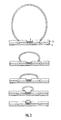
- Fig. 1(a) shows a plan view of a preferred MALDI sample plate, and Fig. 1(b) shows a side view of the MALDI sample plate;
- Fig. 2 shows a sample being deposited on to a sample plate and contracting as the solvent evaporates;
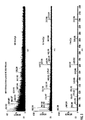
- Fig. 3(a) shows a mass spectrum of ADH protein digest deposited on to a preferred MALDI sample plate at a concentration of 2 attomole/µl, Fig. 3(b) shows a mass spectrum of ADH protein digest deposited on to a preferred MALDI sample plate at a concentration of 20 attomole/µl, and Fig. 3(c) shows a mass spectrum of ADH protein digest deposited on to a preferred MALDI sample plate at a concentration of 200 attomole/µl;
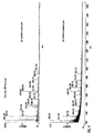
- Figs. 4(a) and (b) show comparative mass spectra from a digest sample of BSA protein (500 fmol originally loaded onto gel) which was spotted onto a preferred MALDI sample plate and a conventional MALDI sample plate;
- Figs. 5(a) and (b) show comparative mass spectra from a digest sample of BSA protein (250 fmol originally loaded onto gel) which was spotted onto a preferred MALDI sample plate and a conventional MALDI sample plate;
- Figs. 6(a) and (b) show comparative mass spectra from a digest sample of BSA protein (100 fmol originally loaded onto gel) which was spotted onto a preferred MALDI sample plate and a conventional MALDI sample plate; and
- Figs. 7(a)-(c) show comparative mass spectra from a 500 fmol digest sample of BSA protein which was spotted on to a preferred MALDI sample plate, a conventional MALDI sample plate after Zip Tip sample preparation and a conventional MALDI sample plate.
-
- By way of background, if a substance is hydrophobic then it will be repelled by water or other highly polar molecules. More specifically, the water molecules tend to repel other non-polar molecules that cannot form hydrogen bonds thereby causing non-polar or hydrophobic molecules to aggregate together (this is also known as the "hydrophobic interaction"). Conversely, water molecules tend to attract and dissolve polar molecules or hydrophilic molecules that can form hydrogen bonds with the water. Hydrophobic interaction is the result of electrostatic forces between polar molecules. These are responsible for pushing hydrophobic molecules together or towards other hydrophobic material such as the reverse phase material in liquid chromatography. This term is sometimes confused with the term affinity which is an attractive force.
- One way of observing hydrophobicity is to observe the contact angle formed between a water droplet or solvent and a substrate. Generally, the higher the contact angle the more hydrophobic the surface. For example, the contact angle between water and PTFE is about 112°. Generally if the contact angle of a liquid on a substrate is less than 90° then the material is said to be wettable (and hence more hydrophilic) by the liquid where the less the angle the greater the level of spreading. If the contact angle is greater than 90° then the material is said to be non wettable (and hence more hydrophobic).
- The surface energy of a solid can also be used to give an indication of hydrophobicity. The lower the surface energy of a solid substrate the greater the contact angle because the molecules of the substrate are not attracting the molecules of the liquid. For example, PTFE has a surface energy of 18 dynes/cm, polystyrene 33 dynes/cm, water 72 dynes/cm and stainless steel 700-1100 dynes/cm. The lower the surface energy the more hydrophobic the material is and conversely, the higher the surface energy the more hydrophilic the material is.
- A preferred MALDI target or sample plate 1 will now be described with regard to Fig. 1. The sample plate 1 comprises a flat conductive metal plate or
substrate 2, preferably stainless steel. Thesubstrate 2 is etched, preferably by a laser, so that a number of circular moat portions orgrooves 3 are produced in thesubstrate 2. Each circular moat portion orgroove 3 defines a sample position. - A high density of sample positions may be provided on the sample plate 1. For ease of illustration only four sample positions are shown in Fig. 1, but according to an embodiment 96 sample positions and 24 reference positions may be provided on a 55 mm x 40 mm steel plate. The
steel plate 2 is approximately 2.5 mm thick. - The
circular moats 3 have a diameter of approximately 2.5 mm and eachmoat 3 is approximately 0.25 mm wide and 0.25 deep. -
Substrate 2 is coated with a hydrophobic material such as polytetrafluoroethylene ("PTFE") which creates a layer approximately 100 µm thick or less. As shown in Fig. 1(b), because of themoat portions 3 there is a dip in thePTFE layer 4 above the correspondingmoat 3. - A laser etched
region 5 is then made in the centre of each sample portion by laser etching or ablation. Each laser etchedregion 5 has a diameter of approximately 0.4-0.6 mm. The precise structure of the laser etchedregion 5 has not been fully investigated but thesteel substrate 2 underneath the upper surface of the laser etchedregion 5 is roughened or indented by the laser etching process. The laser etching process is believed to remove some or all of the PTFE coating leaving behind a roughened region which is presumed to have a large surface area. - The laser etched
region 5 is a roughened region having peaks and troughs. The peak to valley height is approximately 30 µm. - Once the laser etched
regions 5 have been formed, a thin layer of hydrophobic material preferably polystyrene is applied across at least the roughened laser etchedregion 5. It may also be applied across substantially the whole of the upper surface of the sample plate 1. - A preferred sample preparation protocol will now be described.
- A sample is preferably deposited in a relatively large volume of 5-10 µl compared to the sample protocol used with the known sample plate. The sample solution preferably contains analyte and a solvent such as 20-30% acetonitrile ("ACN").
- The large volume sample loading of 5-10 µl is possible because the hydrophobic surface provides an increased contact angle with the sample solution compared to a stainless steel sample plate. In addition, the sample moat geometry maintains the high contact angle and acts as a barrier to the droplet perimeter. The combination of both the hydrophobic surface and the
sample moat 3 gives an approximate 5-10 fold improvement in sample volume retention. - The solvent in the sample solution is allowed to evaporate. During the evaporation the solution droplet is immobilised onto the roughened laser etched
regions 5. Bio-molecules preferentially aggregate on the enlarged hydrophobic surfaces due to hydrophobic interactions. Although both PTFE and polystyrene are highly hydrophobic, it is believed that the relatively large surface area of the hydrophobic coating in the micro structure of the roughened laser etchedregion 5 allows accommodation of a relatively large proportion of the sample over the large surface area of the hydrophobic material within the roughened laser etchedregions 5. - Once the solvent has completely evaporated the analyte bio-molecules are immobilised to the enlarged surface area of hydrophobic coating within the laser etched
regions 5. - According to a particularly preferred embodiment, the sample plate 1 can then be submerged in water to wash the sample and to remove impurities such as inorganic salts. The washed sample can then be analysed directly on the sample plate 1 by the addition of a small volume (1µl) of matrix.
- The matrix preferably comprises α-cyano-4-hydroxycinnamic acid (CHCA). However, other matrices such as 2,5-dihydroxybenzoic acid (DHB), hydroxypicolinic acid (HPA), 3,5-dimethoxy-4-hydroxycinnamic acid (Sinapinic acid), glycerol, succinic acid, thiourea, 2-(4-hydroxypheylazo)benzoic acid (HABA), esculetin and 2,4,5-trihydroxyacetophenone may be used.
- The matrix solvent preferably has a high organic content typically 70-90%. The matrix solvent dissociates the bio-molecules from the roughened laser etched region so allowing the co-crystallisation of analyte and matrix. The matrix droplet is also immobilised onto the roughened laser etched
region 5 and this ensures that the sample is crystallised in a small area. - Fig. 2 shows a sample being deposited on to a sample plate and progressively contracting as the solvent evaporates.
- Figs. 3(a)-(c) show three mass spectra of an in solution tryptic digest sample of Alcohol Dehydrogenase (ADH) protein showing the sensitivity and focusing of different concentrations using the sample plate according to the preferred embodiment. Each sample volume loaded was 5µl. The sample concentrations were 2 attomole/µl (0.01 fmol), 20 attomole/µl (0.1 fmol) and 200 attomole/µl. As is readily apparent from Figs. 3(a) and (b), the detection limit of tryptic peptides using the preferred MALDI sample plate 1 and sample preparation protocols is very low (between 2 and 20 attomole/µl).
- Figs. 4(a) and (b) shows mass spectra from a 500 fmol digest sample of BSA protein that was injected onto a 1D gel plate (Bio-Rad (RTM)). The gel was silver stained and the protein band was cut out and processed using Micromass Massprep (RTM) automated sample preparation station. The automated sample processing included destaining of the cut out gel pieces, reduction and alkylation, tryptic digestion, conditioning and spotting onto the MALDI sample plate 1, washing in situ on the MALDI sample plate 1 (to remove salts) and finally addition of matrix onto the MALDI sample plate 1. Fig. 4(a) shows the resultant mass spectrum where the Massprep loaded 6µl (from a total of 20µl produced) onto a preferred MALDI sample plate 1 and Fig. 4(b) shows the resultant mass spectrum with a standard loading of 2µl onto a conventional MALDI plate.
- The mass spectra shown in Figs. 5(a) and (b) and Figs. 6(a) and (b) were obtained following the same method and using the same sample as described in relation to Figs. 4(a) and (b) except that lower amounts of protein were loaded on to the gel (250fmol and 100fmol respectively).
- As is readily apparent from Figs, 4-6, the detected intensity of the tryptic peptides is much higher on the preferred MALDI sample plate 1 relative to the standard plate and therefore the ultimate detection limit is significantly lower when using the preferred MALDI sample plate 1.
- Finally, Fig. 7 compares mass spectra obtained from using 2µl of the same sample used to obtain the mass spectra shown in Figs. 4-6 loaded onto a preferred MALDI sample plate 1 (Fig. 7(a)), a standard target plate after Zip Tip sample preparation routine (Fig. 7(b)) and a standard stainless steel MALDI sample plate (Fig. 7(c)). Zip Tips (C18) involve binding of analytes to C18 material followed by washing away of salts and subsequent elution onto a sample plate. It is not a direct in-situ method and suffers from transfer losses. It also does not work well with hydrophobic peptides or high concentrations of salts and CHAPS etc. As is readily apparent, the preferred MALDI sample plate 1 produces significantly higher signals and lower noise levels than the Zip Tip method. In this experiment no significant signal was observed when using a standard MALDI plate (Fig. 7(c)).
- Although the present invention has been described with reference to preferred embodiments, it will be understood by those skilled in the art that various changes in form and detail may be made without departing from the scope of the invention as set forth in the accompanying claims.
Claims (51)
- A MALDI sample plate comprising:wherein said sample plate further comprises:a substrate comprising a plurality of sample regions, wherein each sample region comprises:a laser etched portion formed in said substrate;a first portion surrounding at least part or substantially the whole of said laser etched portion; anda groove or raised portion surrounding at least part or substantially the whole of said first portion;a first layer disposed on at least part or substantially the whole of said first portion wherein said first layer comprises a first hydrophobic material.
- A MALDI sample plate as claimed in claim 1, wherein said first layer is also disposed on said groove or raised portion.
- A MALDI sample plate as claimed in claim 1 or 2, wherein said first hydrophobic material is selected from the group consisting of: (i) polytetrafluoroethylene ("PTFE"); and (ii) polystyrene.
- A MALDI sample plate as claimed in claims 1, 2 or 3, wherein said first layer has a thickness selected from the group consisting of: (i) ≤ 5 µm; (ii) 5-10 µm; (iii) 10-15 µm; (iv) 15-20 µm; (v) 20-25 µm; (vi) 25-30 µm; (vii) 30-35 µm; (viii) 35-40 µm; (ix) 40-45 µm; (x) 45-50 µm; (xi) 50-55 µm; (xii) 55-60 µm; (xiii) 60-65 µm; (xiv) 65-70 µm; (xv) 70-75 µm; (xvi) 75-80 µm; (xvii) 80-85 µm; (xviii) 85-90 µm; (xix) 90-95 µm; (xx) 95-100 µm; and (xxi) > 100 µm.
- A MALDI sample plate as claimed in any preceding claim, wherein the contact angle of a solvent or water droplet with said first hydrophobic material is selected from the group consisting of: (i) ≥ 90°; (ii) ≥ 95°; (iii) ≥ 100°; (iv) ≥ 105°; (v) ≥ 110°; (vi) ≥ 115°; and (vii) 110-114°.
- A MALDI sample plate as claimed in any preceding claim, wherein said laser etched portion comprises a roughened region of said substrate.
- A MALDI sample plate as claimed in claim 6, wherein said laser etched portion comprises originally hydrophobic material which has been subsequently polymerized by a laser.
- A MALDI sample plate as claimed in any preceding claim, further comprising a second layer disposed on at least a part or substantially the whole of said laser etched portion.
- A MALDI sample plate as claimed in claim 8, wherein said second layer is also disposed on said first portion.
- A MALDI sample plate as claimed in claim 8 or 9, wherein said second layer is also disposed on said groove or raised portion.
- A MALDI sample plate as claimed in claim 8, 9, or 10, wherein said second layer comprises a second hydrophobic material.
- A MALDI sample plate as claimed in claim 11, wherein said second hydrophobic material is selected from the group consisting of: (i) polystyrene; and (ii) polytetrafluoroethylene ("PTFE").
- A MALDI sample plate as claimed in any of claims 8-12, wherein said second layer has a thickness selected from the group consisting of: (i) ≤ 100 µm; (ii) ≤ 90 µm; (iii) ≤ 80 µm; (iv) ≤ 70 µm; (v) ≤ 60 µm; (vi) ≤ 50 µm; (vii) ≤ 40 µm; (viii) ≤ 30 µm; (ix) ≤ 20 µm; (x) ≤ 10 µm; (xi) ≤ 5 µm; (xii) ≤ 1 µm; (xiii) ≤ 100 nm; (xiv) ≤ 10 nm; (xv) ≤ 1 nm; (xvi) 1-5 monolayers; and (xvii) a single monolayer.
- A MALDI sample plate as claimed in any of claims 8-13, wherein the contact angle of a solvent or water droplet with said second hydrophobic material is selected from the group consisting of: (i) ≥ 90°; (ii) ≥ 95°; (iii) ≥ 100°; (iv) ≥ 105°; (v) ≥ 110°; (vi) ≥ 115°; and (vii) 110-114°.
- A MALDI sample plate as claimed in any preceding claim, wherein said substrate is selected from the group consisting of: (i) metallic; (ii) plastic; (iii) ceramic; (iv) semiconductor; and (v) glass.
- A MALDI sample plate as claimed in any preceding claim, wherein said groove or raised portion is substantially circular.
- A MALDI sample plate as claimed in any preceding claim, wherein said groove or raised portion has an inner diameter selected from the group consisting of: (i) 2.0-2.2 mm; (ii) 2.2-2.4 mm; (iii) 2.4-2.6 mm; (iv) 2.6-2.8 mm; and (v) 2.8-3.0 mm.
- A MALDI sample plate as claimed in claim 17, wherein said groove has a depth or said raised portion has a height selected from the group consisting of: (i) 0.10-0.12; (ii) 0.12-0.14; (iii) 0.14-0.16; (iv) 0.16-0.18; (v) 0.18-0.20; (vi) 0.20-0.22 mm; (vii) 0.22-0.24 mm; (viii) 0.24-0.26 mm; (ix) 0.26-0.28 mm; (x) 0.28-0.30 mm; (xi) 0.30-0.32 mm; (xii) 0.32-0.34 mm; (xiii) 0.34-0.36 mm; (xiv) 0.36-0.38 mm; (xv) 0.38-0.40 mm; (xvi) 0.40-0.42 mm; (xvii) 0.42-0.44 mm; (xviii) 0.44-0.46 mm; (xix) 0.46-0.48 mm; and (xx) 0.48-0.50 mm.
- A MALDI sample plate as claimed in claim 17 or 18, wherein said laser etched portion has a diameter selected from the group consisting of: (i) 0.2-0.4 mm; (ii) 0.4-0.6 mm; (iii) 0.6-0.8 mm; (iv) 0.8-1.0 mm; (v) 1.0-1.2 mm; (vi) 1.2-1.4 mm; (vii) 1.4-1.6 mm; and (viii) 1.6-1.8 mm.
- A MALDI sample plate as claimed in any of claims 1-16, wherein said groove or raised portion has an inner diameter selected from the group consisting of: (i) 1.0-1.2 mm; (ii) 1.2-1.4 mm; (iii) 1.4-1.6 mm; (iv) 1.6-1.8 mm; and (v) 1.8-2.0 mm.
- A MALDI sample plate as claimed in claim 20, wherein said groove has a depth or said raised portion has a height selected from the group consisting of: (i) 0.10-0.12; (ii) 0.12-0.14; (iii) 0.14-0.16; (iv) 0.16-0.18; (v) 0.18-0.20; (vi) 0.20-0.22 mm; (vii) 0.22-0.24 mm; (viii) 0.24-0.26 mm; (ix) 0.26-0.28 mm; (x) 0.28-0.30 mm; (xi) 0.30-0.32 mm; (xii) 0.32-0.34 mm; (xiii) 0.34-0.36 mm; (xiv) 0.36-0.38 mm; (xv) 0.38-0.40 mm; (xvi) 0.40-0.42 mm; (xvii) 0.42-0.44 mm; (xviii) 0.44-0.46 mm; (xix) 0.46-0.48 mm; and (xx) 0.48-0.50 mm.
- A MALDI sample plate as claimed in claim 20 or 21, wherein said laser etched portion has a diameter selected from the group consisting of: (i) 0.2-0.4 mm; (ii) 0.4-0.6 mm; (iii) 0.6-0.8 mm; and (iv) 0.8-1.0 mm.
- A MALDI sample plate as claimed in any preceding claim, wherein said laser etched portion has peaks and troughs which are separated by an average distance selected from the group consisting of: (i) 100-90µm; (ii) 90-80µm; (iii) 80-70µm; (iv) 70-60µm; (v) 60-50µm; (vi) 50-40µm; (vii) 40-30µm; (viii) 30-20µm; (ix) 20-10µm; and (x) 10-1µm.
- A MALDI sample plate as claimed in any preceding claim, wherein said laser etched portion is arranged so as to draw in a sample solution deposited on the sample plate as the volume reduces.
- A MALDI sample plate as claimed in any preceding claim, wherein said sample plate is arranged in a microtitre format.
- A MALDI sample plate as claimed in claim 25, wherein the pitch spacing between samples is approximately or exactly 18 mm, 9 mm, 4.5 mm, 2.25 mm, or 1.125 mm.
- A MALDI sample plate as claimed in claim 25 or 26, wherein up to 48, 96, 384, 1536 or 6144 samples are arranged to be received on said sample plate.
- A MALDI sample plate as claimed in claim 25, 26 or 27, wherein samples are arranged to be deposited on said sample plate in a pattern of four samples about a central control sample well.
- The combination of a MALDI sample plate as claimed in any preceding claim and bio-molecules deposited on to said sample plate.
- A MALDI mass spectrometer in combination with a MALDI sample plate as claimed in any of claims 1-28.
- A sample plate for use in mass spectrometry comprising:a substrate comprising a plurality of sample regions, wherein each sample region comprises:a perimeter defining said sample region;an etched, roughened or indented portion within said perimeter and formed in said substrate; anda hydrophobic surface surrounding and/or covering said etched, roughened or indented portion within said perimeter.
- A sample plate as claimed in claim 31, wherein said perimeter comprises a groove or a raised portion.
- A sample plate as claimed in claim 31, wherein said etched, roughened or indented portion and said hydrophobic surface surrounding said etched, roughened or indented portion are above the surface of said substrate.
- A sample plate as claimed in claim 31, wherein said etched, roughened or indented portion and said hydrophobic surface surrounding said etched, roughened or indented portion are below the surface of said substrate.
- A sample plate for use in mass spectrometry comprising:a plurality of roughened, etched or indented regions each coated with a material having a surface energy selected from the group consisting of: (i) < 72 dynes/cm; (ii) ≤ 70 dynes/cm; (iii) ≤ 60 dynes/cm; (iv) ≤ 50 dynes/cm; (v) ≤ 40 dynes/cm; (vi) ≤ 30 dynes/cm; (vii) ≤ 20 dynes/cm; and (viii) ≤ 10 dynes/cm; anda groove or raised portion surrounding each said roughened, etched or indented region.
- A method of mass spectrometry, comprising the step of using a MALDI sample plate as claimed in any of claims 1-28.
- A method of sample preparation comprising the step of:automatically or manually spotting samples on to a MALDI sample plate as claimed in any of claims 1-28.
- A method of sample preparation comprising the step of:automatically or manually washing samples deposited on to a MALDI sample plate as claimed in any of claims 1-28.
- A method of mass spectrometry comprising the step of:automatically or manually analysing analyte deposited on to a MALDI sample plate as claimed in any of claims 1-28.
- A method of making a MALDI sample plate, comprising the steps of:providing either a substrate having a hydrophobic coating on at least part of the surface of the substrate or a hydrophobic substrate;etching, roughening or indenting at least one etched, roughened or indented portion in said substrate by either: (i) laser ablation; (ii) chemical etching; (iii) electrochemical etching; (iv) mechanical etching; (v) electronbeam etching; or (vi) mechanical pressing; andcoating at least a portion of said at least one etched, roughened or indented portion with a film of hydrophobic material.
- A method of making a sample plate for use in mass spectrometry, comprising the steps of:providing a substrate having a hydrophobic surface and having a plurality of sample regions defined by a plurality of grooves or raised portions;forming a roughened, etched or indented region within at least some of said sample regions; andcoating at least a portion of at least some of said roughened, etched or indented regions with a hydrophobic material.
- A method of preparing a sample on a MALDI sample plate, comprising:providing a MALDI sample plate comprising a roughened, etched or indented region having a hydrophobic coating on at least a portion of said region; anddepositing sample(s) on to said MALDI sample plate, each said sample(s) having a volume selected from the group consisting: (i) 2-4 µl; (ii) 4-6 µl; (iii) 6-8 µl; (iv) 8-10 µl; (v) 10-12 µl; (vi) 12-14 µl; (vii) 14-16 µl; (viii) 16-18 µl; (ix) 18-20 µl; (x) 20-30 µl; (xi) 30-40 µl; (xii) 40-50 µl; (xiii) 50-60 µl; (xiv) 60-70 µl; (xv) 70-80 µl; (xvi) 80-90 µl; and (xvii) 90-100 µl.
- A method of preparing a sample on a MALDI sample plate, comprising:providing a MALDI sample plate comprising a roughened, etched or indented region having a hydrophobic coating on at least a portion of said region;depositing sample(s) which include analyte on to said MALDI sample plate so that said sample(s) attaches to said roughened, etched or indented region;allowing said sample(s) to reduce in volume and so concentrate analyte on to said roughened, etched or indented region; and thenwashing said MALDI sample plate.
- A method of automatically preparing a sample on a sample plate, comprising:providing a sample plate;automatically depositing sample(s) on to said sample plate so that sample(s) attaches to part of the sample plate comprising a roughened, etched or indented region having a hydrophobic coating on at least a portion of said region;allowing said sample(s) to reduce in volume and so concentrate analyte on to said roughened, etched or indented region; and thenautomatically washing said sample plate.
- A method of sample preparation comprising the step of:automatically or manually chemically destaining gel or membrane samples in situ on a MALDI sample plate as claimed in any of claims 1-28.
- A method of sample preparation comprising the step of:automatically or manually chemically reducing samples in situ on a MALDI sample plate as claimed in any of claims 1-28.
- A method of sample preparation comprising the step of:automatically or manually chemically alkylating samples in situ on a MALDI sample plate as claimed in any of claims 1-28.
- A method of sample preparation comprising the step of:automatically or manually tryptically or chemically digesting samples in situ on a MALDI sample plate as claimed in any of claims 1-28.
- A method of sample preparation comprising the step of:automatically or manually chemically derivatising samples in situ a MALDI sample plate as claimed in any of claims 1-28.
- A method of sample preparation comprising the step of:automaticaly or manually washing samples in situ on a MALDI sample plate as claimed in any of claims 1-28 in order to remove gel or membrane samples and/or other contaminants.
- A method of sample preparation comprising at least two, three, four, five or six of the following steps:wherein said MALDI sample plate is a MALDI sample plate as claimed in any of claims 1-28.(i) automatically or manually chemically destaining gel or membrane samples in situ on a MALDI sample plate;(ii) automatically or manually chemically reducing samples in situ on a MALDI sample plate;(iii) automatically or manually chemically alkylating samples in situ on a MALDI sample plate;(iv) automatically or manually tryptically or chemically digesting samples in situ on a MALDI sample plate;(v) automatically or manually chemically derivatising samples in situ a MALDI sample plate; and(vi) automaticaly or manually washing samples in situ on a MALDI sample plate in order to remove gel or membrane samples and/or other contaminants,
Applications Claiming Priority (2)
| Application Number | Priority Date | Filing Date | Title |
|---|---|---|---|
| GB0120131 | 2001-08-17 | ||
| GBGB0120131.8A GB0120131D0 (en) | 2001-08-17 | 2001-08-17 | Maldi target plate |
Publications (3)
| Publication Number | Publication Date |
|---|---|
| EP1284495A2 true EP1284495A2 (en) | 2003-02-19 |
| EP1284495A3 EP1284495A3 (en) | 2005-12-28 |
| EP1284495B1 EP1284495B1 (en) | 2012-05-02 |
Family
ID=9920606
Family Applications (1)
| Application Number | Title | Priority Date | Filing Date |
|---|---|---|---|
| EP02255756A Expired - Lifetime EP1284495B1 (en) | 2001-08-17 | 2002-08-19 | Mass spectrometer |
Country Status (5)
| Country | Link |
|---|---|
| US (2) | US6952011B2 (en) |
| EP (1) | EP1284495B1 (en) |
| AT (1) | ATE555852T1 (en) |
| CA (1) | CA2398680C (en) |
| GB (2) | GB0120131D0 (en) |
Cited By (19)
| Publication number | Priority date | Publication date | Assignee | Title |
|---|---|---|---|---|
| EP1465231A2 (en) * | 2003-03-20 | 2004-10-06 | Agilent Technologies Inc | Methods and devices for performing matrix assisted laser desorption/ionization protocols |
| WO2004109742A2 (en) * | 2003-06-05 | 2004-12-16 | Thermo Finnigan Llc | Rod assembly in ion source |
| WO2005008238A2 (en) * | 2003-07-11 | 2005-01-27 | Commissariat A L'energie Atomique | Method and device for the analysis of living reaction media |
| WO2004108959A3 (en) * | 2003-06-09 | 2005-03-24 | Qinetiq Ltd | Method and apparatus for spore disruption and/or detection |
| WO2005037435A1 (en) * | 2003-10-10 | 2005-04-28 | Applera Corporation | Maldi plate with removable insert |
| US7053366B2 (en) | 2001-05-25 | 2006-05-30 | Waters Investments Limited | Desalting plate for MALDI mass spectrometry |
| WO2006083151A1 (en) * | 2005-02-07 | 2006-08-10 | Yang-Sun Kim | Sample plate for maldi mass spectrometry and process for manufacture of the same |
| EP1756543A2 (en) * | 2004-05-21 | 2007-02-28 | Qiagen Sciences, Inc. | Sample presentation device |
| EP1972919A1 (en) * | 2003-05-13 | 2008-09-24 | Becton, Dickinson and Company | Method and apparatus for processing biological and chemical samples |
| EP2106858A1 (en) * | 2008-03-31 | 2009-10-07 | Sony DADC Austria AG | Substrate and target plate |
| WO2009134120A1 (en) * | 2008-04-29 | 2009-11-05 | Erasmus University Medical Center Rotterdam | Mass spectrometric analysis of small molecule analytes |
| US7619215B2 (en) | 2005-02-07 | 2009-11-17 | Yangsun Kim | Sample plate for MALDI mass spectrometry and process for manufacture of the same |
| WO2011097677A1 (en) * | 2010-02-12 | 2011-08-18 | Monash University | Printed multi-zone microzone plates |
| WO2011144743A1 (en) * | 2010-05-21 | 2011-11-24 | Eidgenössische Technische Hochschule Zürich | High-density sample support plate for automated sample aliquoting |
| WO2014164026A3 (en) * | 2013-03-13 | 2015-02-26 | Sequenom, Inc. | Preparation enhancements and methods of use for maldi mass spectrometry |
| US9310378B2 (en) | 2008-01-15 | 2016-04-12 | Agena Bioscience, Inc. | Compositions and processes for improved mass spectrometry analysis |
| GB2562379A (en) * | 2017-04-13 | 2018-11-14 | Micromass Ltd | Maldi target plate |
| EP3043180B1 (en) * | 2013-09-06 | 2019-08-21 | Nippon Light Metal Company, Ltd. | Biochip |
| EP3418732A4 (en) * | 2016-03-18 | 2019-11-13 | Citizen Finedevice Co., Ltd. | Sample loading plate and manufacturing method of same |
Families Citing this family (50)
| Publication number | Priority date | Publication date | Assignee | Title |
|---|---|---|---|---|
| WO2004072616A2 (en) * | 2003-02-10 | 2004-08-26 | Waters Investments Limited | A sample preparation plate for mass spectrometry |
| AU2003210342A1 (en) * | 2002-02-22 | 2003-09-09 | Scienion Ag | Use of ultraphobic surfaces having a multitude of hydrophilic areas for analyzing samples |
| JP4052094B2 (en) * | 2002-11-11 | 2008-02-27 | 株式会社島津製作所 | Sample preparation method and sample plate used in laser desorption ionization mass spectrometry |
| US7858387B2 (en) * | 2003-04-30 | 2010-12-28 | Perkinelmer Health Sciences, Inc. | Method of scanning a sample plate surface mask in an area adjacent to a conductive area using matrix-assisted laser desorption and ionization mass spectrometry |
| US6891156B2 (en) | 2003-04-30 | 2005-05-10 | Perkin Elmer Instruments Llc | Sample plate for matrix-assisted laser desorption and ionization mass spectrometry |
| DE602004017366D1 (en) * | 2003-05-13 | 2008-12-04 | Hitachi Ltd | Device for irradiation with particle beams and radiation planning unit |
| US7833745B2 (en) * | 2003-09-11 | 2010-11-16 | E. I. Du Pont De Nemours And Company | Direct detection method for products of cellular metabolism using ToF-SIMS |
| EP1676292A4 (en) * | 2003-10-10 | 2009-01-07 | Protein Discovery Inc | Methods and devices for concentration and purification of analytes for chemical analysis including matrix-assisted laser desorption/ionization (maldi) mass spectrometry (ms) |
| US20090215192A1 (en) * | 2004-05-27 | 2009-08-27 | Stratos Biosystems, Llc | Solid-phase affinity-based method for preparing and manipulating an analyte-containing solution |
| JP4441336B2 (en) * | 2004-06-11 | 2010-03-31 | 日本碍子株式会社 | Manufacturing method of microarray |
| DE102004058555A1 (en) * | 2004-12-03 | 2006-06-08 | Qiagen Gmbh | Method of concentrating biomolecules near the surface of a crystalline structure |
| US7262841B2 (en) * | 2005-03-17 | 2007-08-28 | Agilent Technologies, Inc. | Laser alignment for ion source |
| US20060266941A1 (en) * | 2005-05-26 | 2006-11-30 | Vestal Marvin L | Method and apparatus for interfacing separations techniques to MALDI-TOF mass spectrometry |
| WO2007067759A2 (en) * | 2005-12-08 | 2007-06-14 | Protein Discovery, Inc. | Methods and devices for concentration and fractionation of analytes for chemical analysis |
| US7687772B2 (en) * | 2006-01-27 | 2010-03-30 | National Sun Yat-Sen University | Mass spectrometric imaging method under ambient conditions using electrospray-assisted laser desorption ionization mass spectrometry |
| US7465921B1 (en) * | 2006-03-02 | 2008-12-16 | Agilent Technologies, Inc. | Structured carbon nanotube tray for MALDI plates |
| WO2007133714A2 (en) * | 2006-05-12 | 2007-11-22 | Stratos Biosystems, Llc | Analyte focusing biochips for affinity mass spectrometry |
| US20080116366A1 (en) * | 2006-11-17 | 2008-05-22 | Jantaie Shiea | Laser desorption device, mass spectrometer assembly, and method for ambient liquid mass spectrometry |
| US7667195B2 (en) * | 2007-05-01 | 2010-02-23 | Virgin Instruments Corporation | High performance low cost MALDI MS-MS |
| US7663100B2 (en) * | 2007-05-01 | 2010-02-16 | Virgin Instruments Corporation | Reversed geometry MALDI TOF |
| US7564026B2 (en) * | 2007-05-01 | 2009-07-21 | Virgin Instruments Corporation | Linear TOF geometry for high sensitivity at high mass |
| US7589319B2 (en) | 2007-05-01 | 2009-09-15 | Virgin Instruments Corporation | Reflector TOF with high resolution and mass accuracy for peptides and small molecules |
| US7564028B2 (en) * | 2007-05-01 | 2009-07-21 | Virgin Instruments Corporation | Vacuum housing system for MALDI-TOF mass spectrometry |
| US7838824B2 (en) * | 2007-05-01 | 2010-11-23 | Virgin Instruments Corporation | TOF-TOF with high resolution precursor selection and multiplexed MS-MS |
| GB0712795D0 (en) * | 2007-07-02 | 2007-08-08 | Ecole Polytechnique Federale De | Solid phase extraction and ionization device |
| WO2013114217A1 (en) * | 2012-02-05 | 2013-08-08 | Curiox Biosystems Pte Ltd. | Array plates and methods for making and using same |
| US8598511B1 (en) | 2008-03-05 | 2013-12-03 | University Of South Florida | Carbon nanotube anchor for mass spectrometer |
| JP5072682B2 (en) * | 2008-03-28 | 2012-11-14 | 富士フイルム株式会社 | Device for mass spectrometry, mass spectrometer using the same, and mass spectrometry method |
| WO2010014512A2 (en) * | 2008-07-30 | 2010-02-04 | The Brigham And Women's Hospital, Inc. | Preparation of test plates for matrix assisted laser desorption ionization |
| WO2010126897A1 (en) * | 2009-04-27 | 2010-11-04 | Protein Discovery, Inc. | Programmable electrophoretic notch filter systems and methods |
| US9799501B2 (en) * | 2013-08-07 | 2017-10-24 | Citizen Finedevice Co., Ltd. | Sample mounting plate |
| JP6591160B2 (en) * | 2014-12-25 | 2019-10-16 | シチズンファインデバイス株式会社 | Sample loading plate |
| CN107636794B (en) | 2015-03-06 | 2020-02-28 | 英国质谱公司 | Liquid trap or separator for electrosurgical applications |
| EP3265819B1 (en) | 2015-03-06 | 2020-10-14 | Micromass UK Limited | Chemically guided ambient ionisation mass spectrometry |
| JP6858705B2 (en) | 2015-03-06 | 2021-04-14 | マイクロマス ユーケー リミテッド | Collision surface for improved ionization |
| US10777397B2 (en) | 2015-03-06 | 2020-09-15 | Micromass Uk Limited | Inlet instrumentation for ion analyser coupled to rapid evaporative ionisation mass spectrometry (“REIMS”) device |
| US11367605B2 (en) | 2015-03-06 | 2022-06-21 | Micromass Uk Limited | Ambient ionization mass spectrometry imaging platform for direct mapping from bulk tissue |
| CN107580675B (en) | 2015-03-06 | 2020-12-08 | 英国质谱公司 | Rapid evaporative ionization mass spectrometry ("REIMS") and desorption electrospray ionization mass spectrometry ("DESI-MS") analysis of swab and biopsy samples |
| WO2016142692A1 (en) | 2015-03-06 | 2016-09-15 | Micromass Uk Limited | Spectrometric analysis |
| EP3265822B1 (en) | 2015-03-06 | 2021-04-28 | Micromass UK Limited | Tissue analysis by mass spectrometry or ion mobility spectrometry |
| GB2554206B (en) | 2015-03-06 | 2021-03-24 | Micromass Ltd | Spectrometric analysis of microbes |
| KR102017409B1 (en) | 2015-03-06 | 2019-10-21 | 마이크로매스 유케이 리미티드 | Improved Ionization Methods for Gaseous Samples |
| GB2556436B (en) | 2015-03-06 | 2022-01-26 | Micromass Ltd | Cell population analysis |
| US11139156B2 (en) | 2015-03-06 | 2021-10-05 | Micromass Uk Limited | In vivo endoscopic tissue identification tool |
| EP3265818B1 (en) | 2015-03-06 | 2020-02-12 | Micromass UK Limited | Imaging guided ambient ionisation mass spectrometry |
| DE202016008460U1 (en) * | 2015-03-06 | 2018-01-22 | Micromass Uk Limited | Cell population analysis |
| GB201517195D0 (en) | 2015-09-29 | 2015-11-11 | Micromass Ltd | Capacitively coupled reims technique and optically transparent counter electrode |
| EP3443354A1 (en) | 2016-04-14 | 2019-02-20 | Micromass UK Limited | Spectrometric analysis of plants |
| JP2022094173A (en) * | 2020-12-14 | 2022-06-24 | 浜松ホトニクス株式会社 | Sample support, ionization method, and mass spectrometry method |
| GB2605958A (en) * | 2021-04-15 | 2022-10-26 | Micromass Ltd | Ion source sample plate |
Citations (4)
| Publication number | Priority date | Publication date | Assignee | Title |
|---|---|---|---|---|
| WO1993000700A1 (en) * | 1991-06-21 | 1993-01-07 | Finnigan Mat Limited | Sample holder for use in a mass spectrometer |
| WO1999000657A1 (en) * | 1997-06-26 | 1999-01-07 | Perseptive Biosystems, Inc. | High density sample holder for analysis of biological samples |
| GB2332273A (en) * | 1997-12-11 | 1999-06-16 | Bruker Daltonik Gmbh | Sample support for mass spectroscopy |
| WO2000067293A1 (en) * | 1999-04-29 | 2000-11-09 | Ciphergen Biosystems, Inc. | Sample holder with hydrophobic coating for gas phase mass spectrometers |
Family Cites Families (32)
| Publication number | Priority date | Publication date | Assignee | Title |
|---|---|---|---|---|
| US10908A (en) * | 1854-05-16 | Table fob ships cabin s | ||
| US150903A (en) * | 1874-05-12 | Improvement in feathering paddle-wheels | ||
| US68133A (en) * | 1867-08-27 | Richabd vose | ||
| US51738A (en) * | 1865-12-26 | Improvement in horseshoes | ||
| US626575A (en) * | 1899-06-06 | Eyeglass-gage | ||
| US57368A (en) * | 1866-08-21 | Stove-pipe damper | ||
| US121595A (en) * | 1871-12-05 | Improvement in the manufacture of bleaching-powders, sulphates | ||
| US4405692A (en) * | 1981-12-04 | 1983-09-20 | Hughes Aircraft Company | Moisture-protected alkali halide infrared windows |
| US5605798A (en) | 1993-01-07 | 1997-02-25 | Sequenom, Inc. | DNA diagnostic based on mass spectrometry |
| ES2201077T3 (en) * | 1993-05-28 | 2004-03-16 | Baylor College Of Medicine | METHOD AND SPECTROMETER OF MASSES FOR DESORTION AND IONIZATION OF ANALYTS. |
| US6071610A (en) * | 1993-11-12 | 2000-06-06 | Waters Investments Limited | Enhanced resolution matrix-laser desorption and ionization TOF-MS sample surface |
| US6004770A (en) * | 1995-06-07 | 1999-12-21 | Arizona State University Board Of Regents | Sample presentation apparatus for mass spectrometry |
| DE19617011C2 (en) * | 1996-04-27 | 2000-11-02 | Bruker Daltonik Gmbh | Matrix component mixture for matrix-assisted laser desorption and ionization and method for preparing a matrix component mixture |
| DE19618032C2 (en) | 1996-05-04 | 2000-04-13 | Bruker Daltonik Gmbh | Prepared Maldi sample carriers that can be stored |
| NZ516848A (en) * | 1997-06-20 | 2004-03-26 | Ciphergen Biosystems Inc | Retentate chromatography apparatus with applications in biology and medicine |
| US6893877B2 (en) | 1998-01-12 | 2005-05-17 | Massachusetts Institute Of Technology | Methods for screening substances in a microwell array |
| DE69930726T2 (en) | 1998-01-12 | 2007-01-25 | Massachusetts Institute Of Technology, Cambridge | METHOD AND DEVICE FOR MICROTEST PROCESSING |
| US6265715B1 (en) * | 1998-02-02 | 2001-07-24 | Helene Perreault | Non-porous membrane for MALDI-TOFMS |
| US6897072B1 (en) | 1999-04-27 | 2005-05-24 | Ciphergen Biosystems, Inc. | Probes for a gas phase ion spectrometer |
| WO2000077812A2 (en) | 1999-06-10 | 2000-12-21 | Northeastern University | Light-induced electron capture at a surface |
| JP3548769B2 (en) | 1999-06-29 | 2004-07-28 | 旭テクネイオン株式会社 | Carbon support plate for forming fine and uniform crystals and its application |
| WO2001019520A1 (en) | 1999-09-13 | 2001-03-22 | Millipore Corporation | High density cast-in-place sample preparation card |
| WO2002001599A2 (en) * | 2000-06-28 | 2002-01-03 | The Johns Hopkins University | Time-of-flight mass spectrometer array instrument |
| DE10043042C2 (en) | 2000-09-01 | 2003-04-17 | Bruker Daltonik Gmbh | Method for loading a sample carrier with biomolecules for mass spectrometric analysis |
| US6539102B1 (en) * | 2000-09-01 | 2003-03-25 | Large Scale Proteomics | Reference database |
| WO2002030561A2 (en) | 2000-10-10 | 2002-04-18 | Biotrove, Inc. | Apparatus for assay, synthesis and storage, and methods of manufacture, use, and manipulation thereof |
| US6825477B2 (en) | 2001-02-28 | 2004-11-30 | Jan Sunner | Method and apparatus to produce gas phase analyte ions |
| EP1395824A1 (en) | 2001-05-14 | 2004-03-10 | The Penn State Research Foundation | Matrix-free desorption ionization mass spectrometry using tailored morphology layer devices |
| WO2002097392A2 (en) | 2001-05-25 | 2002-12-05 | Waters Investments Limited | Sample concentration maldi plates for maldi mass spectrometry |
| US20030010908A1 (en) | 2001-07-02 | 2003-01-16 | Phillip Clark | Conductive card suitable as a MALDI-TOF target |
| DE10140499B4 (en) | 2001-08-17 | 2005-02-03 | Bruker Daltonik Gmbh | Sample carrier plates for mass spectrometry with ionization by matrix-assisted laser desorption |
| US20040058059A1 (en) * | 2001-11-07 | 2004-03-25 | Linford Mathew Richard | Funtionalized patterned surfaces |
-
2001
- 2001-08-17 GB GBGB0120131.8A patent/GB0120131D0/en not_active Ceased
-
2002
- 2002-08-16 CA CA2398680A patent/CA2398680C/en not_active Expired - Lifetime
- 2002-08-19 AT AT02255756T patent/ATE555852T1/en active
- 2002-08-19 EP EP02255756A patent/EP1284495B1/en not_active Expired - Lifetime
- 2002-08-19 US US10/223,401 patent/US6952011B2/en not_active Expired - Lifetime
- 2002-08-19 GB GB0219309A patent/GB2381068B/en not_active Expired - Fee Related
-
2005
- 2005-08-03 US US11/196,820 patent/US7294831B2/en not_active Expired - Fee Related
Patent Citations (4)
| Publication number | Priority date | Publication date | Assignee | Title |
|---|---|---|---|---|
| WO1993000700A1 (en) * | 1991-06-21 | 1993-01-07 | Finnigan Mat Limited | Sample holder for use in a mass spectrometer |
| WO1999000657A1 (en) * | 1997-06-26 | 1999-01-07 | Perseptive Biosystems, Inc. | High density sample holder for analysis of biological samples |
| GB2332273A (en) * | 1997-12-11 | 1999-06-16 | Bruker Daltonik Gmbh | Sample support for mass spectroscopy |
| WO2000067293A1 (en) * | 1999-04-29 | 2000-11-09 | Ciphergen Biosystems, Inc. | Sample holder with hydrophobic coating for gas phase mass spectrometers |
Cited By (38)
| Publication number | Priority date | Publication date | Assignee | Title |
|---|---|---|---|---|
| US7053366B2 (en) | 2001-05-25 | 2006-05-30 | Waters Investments Limited | Desalting plate for MALDI mass spectrometry |
| EP1465231A2 (en) * | 2003-03-20 | 2004-10-06 | Agilent Technologies Inc | Methods and devices for performing matrix assisted laser desorption/ionization protocols |
| EP1465231A3 (en) * | 2003-03-20 | 2005-06-08 | Agilent Technologies Inc | Methods and devices for performing matrix assisted laser desorption/ionization protocols |
| EP1972919A1 (en) * | 2003-05-13 | 2008-09-24 | Becton, Dickinson and Company | Method and apparatus for processing biological and chemical samples |
| GB2417823B (en) * | 2003-06-05 | 2006-08-30 | Thermo Finnigan Llc | Rod assembly in ion source |
| WO2004109742A2 (en) * | 2003-06-05 | 2004-12-16 | Thermo Finnigan Llc | Rod assembly in ion source |
| DE112004000929B4 (en) * | 2003-06-05 | 2010-09-02 | Thermo Finnigan Llc, San Jose | Bar arrangement in an ion source |
| WO2004109742A3 (en) * | 2003-06-05 | 2005-10-06 | Thermo Finnigan Llc | Rod assembly in ion source |
| US6963066B2 (en) | 2003-06-05 | 2005-11-08 | Thermo Finnigan Llc | Rod assembly in ion source |
| GB2417823A (en) * | 2003-06-05 | 2006-03-08 | Thermo Finnigan Llc | Rod assembly in ion source |
| US8338092B2 (en) | 2003-06-09 | 2012-12-25 | Qinetiq Limited | Method and apparatus for spore disruption and/or detection |
| WO2004108959A3 (en) * | 2003-06-09 | 2005-03-24 | Qinetiq Ltd | Method and apparatus for spore disruption and/or detection |
| US7785890B2 (en) | 2003-07-11 | 2010-08-31 | Commissariat A L'energie Atomique | Method and device for the analysis of living reaction media |
| WO2005008238A3 (en) * | 2003-07-11 | 2005-03-17 | Commissariat Energie Atomique | Method and device for the analysis of living reaction media |
| WO2005008238A2 (en) * | 2003-07-11 | 2005-01-27 | Commissariat A L'energie Atomique | Method and device for the analysis of living reaction media |
| WO2005037435A1 (en) * | 2003-10-10 | 2005-04-28 | Applera Corporation | Maldi plate with removable insert |
| EP1756543A4 (en) * | 2004-05-21 | 2013-01-16 | Qiagen Sciences Inc | Sample presentation device |
| EP1756543A2 (en) * | 2004-05-21 | 2007-02-28 | Qiagen Sciences, Inc. | Sample presentation device |
| WO2006083151A1 (en) * | 2005-02-07 | 2006-08-10 | Yang-Sun Kim | Sample plate for maldi mass spectrometry and process for manufacture of the same |
| US7619215B2 (en) | 2005-02-07 | 2009-11-17 | Yangsun Kim | Sample plate for MALDI mass spectrometry and process for manufacture of the same |
| US10329612B2 (en) | 2008-01-15 | 2019-06-25 | Agena Bioscience, Inc. | Compositions and processes for improved mass spectrometry analysis |
| US9873912B2 (en) | 2008-01-15 | 2018-01-23 | Agena Bioscience, Inc. | Compositions and processes for improved mass spectrometry analysis |
| US9310378B2 (en) | 2008-01-15 | 2016-04-12 | Agena Bioscience, Inc. | Compositions and processes for improved mass spectrometry analysis |
| US9176030B2 (en) | 2008-03-31 | 2015-11-03 | Sony Dadc Austria Ag | Substrate and target plate |
| EP2106858A1 (en) * | 2008-03-31 | 2009-10-07 | Sony DADC Austria AG | Substrate and target plate |
| WO2009134120A1 (en) * | 2008-04-29 | 2009-11-05 | Erasmus University Medical Center Rotterdam | Mass spectrometric analysis of small molecule analytes |
| WO2011097677A1 (en) * | 2010-02-12 | 2011-08-18 | Monash University | Printed multi-zone microzone plates |
| WO2011144743A1 (en) * | 2010-05-21 | 2011-11-24 | Eidgenössische Technische Hochschule Zürich | High-density sample support plate for automated sample aliquoting |
| US9211542B2 (en) | 2010-05-21 | 2015-12-15 | Eidgenossische Technische Hochschule Zurich | High-density sample support plate for automated sample aliquoting |
| US9305756B2 (en) | 2013-03-13 | 2016-04-05 | Agena Bioscience, Inc. | Preparation enhancements and methods of use for MALDI mass spectrometry |
| WO2014164026A3 (en) * | 2013-03-13 | 2015-02-26 | Sequenom, Inc. | Preparation enhancements and methods of use for maldi mass spectrometry |
| US10204771B2 (en) | 2013-03-13 | 2019-02-12 | Agena Bioscience, Inc. | Preparation enhancements and methods of use for MALDI mass spectrometry |
| EP3043180B1 (en) * | 2013-09-06 | 2019-08-21 | Nippon Light Metal Company, Ltd. | Biochip |
| EP3546942A1 (en) * | 2013-09-06 | 2019-10-02 | Nippon Light Metal Company, Ltd. | Biochip |
| EP3418732A4 (en) * | 2016-03-18 | 2019-11-13 | Citizen Finedevice Co., Ltd. | Sample loading plate and manufacturing method of same |
| US10665445B2 (en) | 2016-03-18 | 2020-05-26 | Citizen Finedevice Co., Ltd. | Sample mounting plate and method for manufacturing the same |
| GB2562379A (en) * | 2017-04-13 | 2018-11-14 | Micromass Ltd | Maldi target plate |
| GB2562379B (en) * | 2017-04-13 | 2021-12-29 | Micromass Ltd | Maldi target plate |
Also Published As
| Publication number | Publication date |
|---|---|
| CA2398680A1 (en) | 2003-02-17 |
| GB2381068A (en) | 2003-04-23 |
| US6952011B2 (en) | 2005-10-04 |
| US7294831B2 (en) | 2007-11-13 |
| GB0120131D0 (en) | 2001-10-10 |
| US20030116707A1 (en) | 2003-06-26 |
| EP1284495A3 (en) | 2005-12-28 |
| GB2381068C (en) | 2003-09-10 |
| GB0219309D0 (en) | 2002-09-25 |
| GB2381068B (en) | 2003-09-10 |
| ATE555852T1 (en) | 2012-05-15 |
| CA2398680C (en) | 2010-10-26 |
| US20050274885A1 (en) | 2005-12-15 |
| EP1284495B1 (en) | 2012-05-02 |
Similar Documents
| Publication | Publication Date | Title |
|---|---|---|
| US7294831B2 (en) | MALDI sample plate | |
| Kussmann et al. | Sample preparation techniques for peptides and proteins analyzed by MALDI-MS | |
| US5595636A (en) | Method for mass spectrometric analysis of samples from electrophoresis plates | |
| Gobom et al. | Sample purification and preparation technique based on nano‐scale reversed‐phase columns for the sensitive analysis of complex peptide mixtures by matrix‐assisted laser desorption/ionization mass spectrometry | |
| US7361311B2 (en) | System and method for the preparation of arrays of biological or other molecules | |
| US20030138823A1 (en) | Sample preparation methods for maldi mass spectrometry | |
| US6995363B2 (en) | Reduction of matrix interference for MALDI mass spectrometry analysis | |
| US9211542B2 (en) | High-density sample support plate for automated sample aliquoting | |
| Foret et al. | Liquid phase interfacing and miniaturization in matrix‐assisted laser desorption/ionization mass spectrometry | |
| US20060079002A1 (en) | System and method for landing of ions on a gas/liquid interface | |
| CA2560115A1 (en) | System and method for preparative mass spectrometry | |
| WO2003054915A1 (en) | Target plate for mass spectometers and use thereof | |
| US20100148052A1 (en) | Analytical carrier and application thereof | |
| WO2006083151A1 (en) | Sample plate for maldi mass spectrometry and process for manufacture of the same | |
| Li et al. | Silicone/graphite coating for on‐target desalting and improved peptide mapping performance of matrix‐assisted laser desorption/ionization‐mass spectrometry targets in proteomic experiments | |
| US20030180957A1 (en) | Target and method | |
| WO2005019875A2 (en) | Electrowetting sample presentation device | |
| Shen et al. | Preparation and characterization of nitrilotriacetic-acid-terminated self-assembled monolayers on gold surfaces for matrix-assisted laser desorption ionization-time of flight-mass spectrometry analysis of proteins and peptides | |
| Hua et al. | Novel polymer composite to eliminate background matrix ions in matrix assisted laser desorption/ionization-mass spectrometry | |
| Afonso et al. | Activated surfaces for laser desorption mass spectrometry: application for peptide and protein analysis | |
| JP4432411B2 (en) | Laser desorption ionization mass spectrometry | |
| Rechthaler et al. | A one-way hydrophobic surface foil as sample support for MALDI and off-line CZE/MALDI mass spectrometry: An alternative for low and high molecular mass compounds | |
| KR101345674B1 (en) | Hydrophilic/hydrophobic patterned biochips for on chip MALDI-TOF MS | |
| Dias | A microdevice for the improved presentation of biological samples for MALDI-TOF mass spectrometry | |
| Iakab et al. | Gold-coated Black Silicon: An Efficient Substrate for Laser Desorption Ionization Mass Spectrometry Applications |
Legal Events
| Date | Code | Title | Description |
|---|---|---|---|
| PUAI | Public reference made under article 153(3) epc to a published international application that has entered the european phase |
Free format text: ORIGINAL CODE: 0009012 |
|
| AK | Designated contracting states |
Designated state(s): AT BE BG CH CY CZ DE DK EE ES FI FR GB GR IE IT LI LU MC NL PT SE SK TR |
|
| AX | Request for extension of the european patent |
Extension state: AL LT LV MK RO SI |
|
| RAP1 | Party data changed (applicant data changed or rights of an application transferred) |
Owner name: MICROMASS UK LIMITED |
|
| PUAL | Search report despatched |
Free format text: ORIGINAL CODE: 0009013 |
|
| AK | Designated contracting states |
Kind code of ref document: A3 Designated state(s): AT BE BG CH CY CZ DE DK EE ES FI FR GB GR IE IT LI LU MC NL PT SE SK TR |
|
| AX | Request for extension of the european patent |
Extension state: AL LT LV MK RO SI |
|
| 17P | Request for examination filed |
Effective date: 20060626 |
|
| AKX | Designation fees paid |
Designated state(s): AT BE BG CH CY CZ DE DK EE ES FI FR GB GR IE IT LI LU MC NL PT SE SK TR |
|
| RIC1 | Information provided on ipc code assigned before grant |
Ipc: H01J 49/04 20060101ALI20101220BHEP Ipc: H01J 49/16 20060101AFI20101220BHEP |
|
| REG | Reference to a national code |
Ref country code: DE Ref legal event code: R079 Ref document number: 60242792 Country of ref document: DE Free format text: PREVIOUS MAIN CLASS: H01J0049400000 Ipc: B01L0003000000 |
|
| GRAP | Despatch of communication of intention to grant a patent |
Free format text: ORIGINAL CODE: EPIDOSNIGR1 |
|
| RIC1 | Information provided on ipc code assigned before grant |
Ipc: B01L 3/00 20060101AFI20120105BHEP Ipc: H01J 49/04 20060101ALI20120105BHEP |
|
| RBV | Designated contracting states (corrected) |
Designated state(s): AT BE BG CH CY CZ DE DK EE ES FI FR GR IE IT LI LU MC NL PT SE SK TR |
|
| GRAS | Grant fee paid |
Free format text: ORIGINAL CODE: EPIDOSNIGR3 |
|
| GRAA | (expected) grant |
Free format text: ORIGINAL CODE: 0009210 |
|
| AK | Designated contracting states |
Kind code of ref document: B1 Designated state(s): AT BE BG CH CY CZ DE DK EE ES FI FR GR IE IT LI LU MC NL PT SE SK TR |
|
| REG | Reference to a national code |
Ref country code: CH Ref legal event code: EP Ref country code: AT Ref legal event code: REF Ref document number: 555852 Country of ref document: AT Kind code of ref document: T Effective date: 20120515 |
|
| REG | Reference to a national code |
Ref country code: IE Ref legal event code: FG4D |
|
| REG | Reference to a national code |
Ref country code: DE Ref legal event code: R096 Ref document number: 60242792 Country of ref document: DE Effective date: 20120705 |
|
| REG | Reference to a national code |
Ref country code: NL Ref legal event code: VDEP Effective date: 20120502 |
|
| PG25 | Lapsed in a contracting state [announced via postgrant information from national office to epo] |
Ref country code: CY Free format text: LAPSE BECAUSE OF FAILURE TO SUBMIT A TRANSLATION OF THE DESCRIPTION OR TO PAY THE FEE WITHIN THE PRESCRIBED TIME-LIMIT Effective date: 20120502 Ref country code: SE Free format text: LAPSE BECAUSE OF FAILURE TO SUBMIT A TRANSLATION OF THE DESCRIPTION OR TO PAY THE FEE WITHIN THE PRESCRIBED TIME-LIMIT Effective date: 20120502 Ref country code: FI Free format text: LAPSE BECAUSE OF FAILURE TO SUBMIT A TRANSLATION OF THE DESCRIPTION OR TO PAY THE FEE WITHIN THE PRESCRIBED TIME-LIMIT Effective date: 20120502 |
|
| REG | Reference to a national code |
Ref country code: AT Ref legal event code: MK05 Ref document number: 555852 Country of ref document: AT Kind code of ref document: T Effective date: 20120502 |
|
| PG25 | Lapsed in a contracting state [announced via postgrant information from national office to epo] |
Ref country code: PT Free format text: LAPSE BECAUSE OF FAILURE TO SUBMIT A TRANSLATION OF THE DESCRIPTION OR TO PAY THE FEE WITHIN THE PRESCRIBED TIME-LIMIT Effective date: 20120903 Ref country code: GR Free format text: LAPSE BECAUSE OF FAILURE TO SUBMIT A TRANSLATION OF THE DESCRIPTION OR TO PAY THE FEE WITHIN THE PRESCRIBED TIME-LIMIT Effective date: 20120803 |
|
| PG25 | Lapsed in a contracting state [announced via postgrant information from national office to epo] |
Ref country code: BE Free format text: LAPSE BECAUSE OF FAILURE TO SUBMIT A TRANSLATION OF THE DESCRIPTION OR TO PAY THE FEE WITHIN THE PRESCRIBED TIME-LIMIT Effective date: 20120502 |
|
| PG25 | Lapsed in a contracting state [announced via postgrant information from national office to epo] |
Ref country code: CZ Free format text: LAPSE BECAUSE OF FAILURE TO SUBMIT A TRANSLATION OF THE DESCRIPTION OR TO PAY THE FEE WITHIN THE PRESCRIBED TIME-LIMIT Effective date: 20120502 Ref country code: NL Free format text: LAPSE BECAUSE OF FAILURE TO SUBMIT A TRANSLATION OF THE DESCRIPTION OR TO PAY THE FEE WITHIN THE PRESCRIBED TIME-LIMIT Effective date: 20120502 Ref country code: EE Free format text: LAPSE BECAUSE OF FAILURE TO SUBMIT A TRANSLATION OF THE DESCRIPTION OR TO PAY THE FEE WITHIN THE PRESCRIBED TIME-LIMIT Effective date: 20120502 Ref country code: AT Free format text: LAPSE BECAUSE OF FAILURE TO SUBMIT A TRANSLATION OF THE DESCRIPTION OR TO PAY THE FEE WITHIN THE PRESCRIBED TIME-LIMIT Effective date: 20120502 Ref country code: DK Free format text: LAPSE BECAUSE OF FAILURE TO SUBMIT A TRANSLATION OF THE DESCRIPTION OR TO PAY THE FEE WITHIN THE PRESCRIBED TIME-LIMIT Effective date: 20120502 Ref country code: SK Free format text: LAPSE BECAUSE OF FAILURE TO SUBMIT A TRANSLATION OF THE DESCRIPTION OR TO PAY THE FEE WITHIN THE PRESCRIBED TIME-LIMIT Effective date: 20120502 |
|
| PG25 | Lapsed in a contracting state [announced via postgrant information from national office to epo] |
Ref country code: IT Free format text: LAPSE BECAUSE OF FAILURE TO SUBMIT A TRANSLATION OF THE DESCRIPTION OR TO PAY THE FEE WITHIN THE PRESCRIBED TIME-LIMIT Effective date: 20120502 |
|
| PLBE | No opposition filed within time limit |
Free format text: ORIGINAL CODE: 0009261 |
|
| STAA | Information on the status of an ep patent application or granted ep patent |
Free format text: STATUS: NO OPPOSITION FILED WITHIN TIME LIMIT |
|
| REG | Reference to a national code |
Ref country code: CH Ref legal event code: PL |
|
| PG25 | Lapsed in a contracting state [announced via postgrant information from national office to epo] |
Ref country code: MC Free format text: LAPSE BECAUSE OF NON-PAYMENT OF DUE FEES Effective date: 20120831 |
|
| 26N | No opposition filed |
Effective date: 20130205 |
|
| PG25 | Lapsed in a contracting state [announced via postgrant information from national office to epo] |
Ref country code: LI Free format text: LAPSE BECAUSE OF NON-PAYMENT OF DUE FEES Effective date: 20120831 Ref country code: CH Free format text: LAPSE BECAUSE OF NON-PAYMENT OF DUE FEES Effective date: 20120831 Ref country code: ES Free format text: LAPSE BECAUSE OF FAILURE TO SUBMIT A TRANSLATION OF THE DESCRIPTION OR TO PAY THE FEE WITHIN THE PRESCRIBED TIME-LIMIT Effective date: 20120813 |
|
| REG | Reference to a national code |
Ref country code: IE Ref legal event code: MM4A |
|
| REG | Reference to a national code |
Ref country code: DE Ref legal event code: R097 Ref document number: 60242792 Country of ref document: DE Effective date: 20130205 |
|
| PG25 | Lapsed in a contracting state [announced via postgrant information from national office to epo] |
Ref country code: BG Free format text: LAPSE BECAUSE OF FAILURE TO SUBMIT A TRANSLATION OF THE DESCRIPTION OR TO PAY THE FEE WITHIN THE PRESCRIBED TIME-LIMIT Effective date: 20120802 Ref country code: IE Free format text: LAPSE BECAUSE OF NON-PAYMENT OF DUE FEES Effective date: 20120819 |
|
| PG25 | Lapsed in a contracting state [announced via postgrant information from national office to epo] |
Ref country code: TR Free format text: LAPSE BECAUSE OF FAILURE TO SUBMIT A TRANSLATION OF THE DESCRIPTION OR TO PAY THE FEE WITHIN THE PRESCRIBED TIME-LIMIT Effective date: 20120502 |
|
| PG25 | Lapsed in a contracting state [announced via postgrant information from national office to epo] |
Ref country code: LU Free format text: LAPSE BECAUSE OF NON-PAYMENT OF DUE FEES Effective date: 20120819 |
|
| REG | Reference to a national code |
Ref country code: FR Ref legal event code: PLFP Year of fee payment: 15 |
|
| REG | Reference to a national code |
Ref country code: FR Ref legal event code: PLFP Year of fee payment: 16 |
|
| PGFP | Annual fee paid to national office [announced via postgrant information from national office to epo] |
Ref country code: FR Payment date: 20170825 Year of fee payment: 16 |
|
| PGFP | Annual fee paid to national office [announced via postgrant information from national office to epo] |
Ref country code: DE Payment date: 20180719 Year of fee payment: 17 |
|
| PG25 | Lapsed in a contracting state [announced via postgrant information from national office to epo] |
Ref country code: FR Free format text: LAPSE BECAUSE OF NON-PAYMENT OF DUE FEES Effective date: 20180831 |
|
| REG | Reference to a national code |
Ref country code: DE Ref legal event code: R119 Ref document number: 60242792 Country of ref document: DE |
|
| PG25 | Lapsed in a contracting state [announced via postgrant information from national office to epo] |
Ref country code: DE Free format text: LAPSE BECAUSE OF NON-PAYMENT OF DUE FEES Effective date: 20200303 |