EP1285847A1 - Tail lamp structure for motorcycle - Google Patents
Tail lamp structure for motorcycle Download PDFInfo
- Publication number
- EP1285847A1 EP1285847A1 EP02013760A EP02013760A EP1285847A1 EP 1285847 A1 EP1285847 A1 EP 1285847A1 EP 02013760 A EP02013760 A EP 02013760A EP 02013760 A EP02013760 A EP 02013760A EP 1285847 A1 EP1285847 A1 EP 1285847A1
- Authority
- EP
- European Patent Office
- Prior art keywords
- tail lamp
- rear fender
- disposed
- cowl
- fender
- Prior art date
- Legal status (The legal status is an assumption and is not a legal conclusion. Google has not performed a legal analysis and makes no representation as to the accuracy of the status listed.)
- Granted
Links
Images


Classifications
-
- B—PERFORMING OPERATIONS; TRANSPORTING
- B62—LAND VEHICLES FOR TRAVELLING OTHERWISE THAN ON RAILS
- B62J—CYCLE SADDLES OR SEATS; AUXILIARY DEVICES OR ACCESSORIES SPECIALLY ADAPTED TO CYCLES AND NOT OTHERWISE PROVIDED FOR, e.g. ARTICLE CARRIERS OR CYCLE PROTECTORS
- B62J6/00—Arrangement of optical signalling or lighting devices on cycles; Mounting or supporting thereof; Circuits therefor
- B62J6/04—Rear lights
- B62J6/045—Rear lights indicating braking
-
- B—PERFORMING OPERATIONS; TRANSPORTING
- B60—VEHICLES IN GENERAL
- B60Q—ARRANGEMENT OF SIGNALLING OR LIGHTING DEVICES, THE MOUNTING OR SUPPORTING THEREOF OR CIRCUITS THEREFOR, FOR VEHICLES IN GENERAL
- B60Q1/00—Arrangement of optical signalling or lighting devices, the mounting or supporting thereof or circuits therefor
- B60Q1/26—Arrangement of optical signalling or lighting devices, the mounting or supporting thereof or circuits therefor the devices being primarily intended to indicate the vehicle, or parts thereof, or to give signals, to other traffic
- B60Q1/30—Arrangement of optical signalling or lighting devices, the mounting or supporting thereof or circuits therefor the devices being primarily intended to indicate the vehicle, or parts thereof, or to give signals, to other traffic for indicating rear of vehicle, e.g. by means of reflecting surfaces
-
- F—MECHANICAL ENGINEERING; LIGHTING; HEATING; WEAPONS; BLASTING
- F21—LIGHTING
- F21S—NON-PORTABLE LIGHTING DEVICES; SYSTEMS THEREOF; VEHICLE LIGHTING DEVICES SPECIALLY ADAPTED FOR VEHICLE EXTERIORS
- F21S43/00—Signalling devices specially adapted for vehicle exteriors, e.g. brake lamps, direction indicator lights or reversing lights
- F21S43/10—Signalling devices specially adapted for vehicle exteriors, e.g. brake lamps, direction indicator lights or reversing lights characterised by the light source
- F21S43/13—Signalling devices specially adapted for vehicle exteriors, e.g. brake lamps, direction indicator lights or reversing lights characterised by the light source characterised by the type of light source
- F21S43/14—Light emitting diodes [LED]
-
- B—PERFORMING OPERATIONS; TRANSPORTING
- B60—VEHICLES IN GENERAL
- B60Y—INDEXING SCHEME RELATING TO ASPECTS CROSS-CUTTING VEHICLE TECHNOLOGY
- B60Y2200/00—Type of vehicle
- B60Y2200/10—Road Vehicles
- B60Y2200/12—Motorcycles, Trikes; Quads; Scooters
-
- F—MECHANICAL ENGINEERING; LIGHTING; HEATING; WEAPONS; BLASTING
- F21—LIGHTING
- F21W—INDEXING SCHEME ASSOCIATED WITH SUBCLASSES F21K, F21L, F21S and F21V, RELATING TO USES OR APPLICATIONS OF LIGHTING DEVICES OR SYSTEMS
- F21W2103/00—Exterior vehicle lighting devices for signalling purposes
- F21W2103/35—Brake lights
-
- F—MECHANICAL ENGINEERING; LIGHTING; HEATING; WEAPONS; BLASTING
- F21—LIGHTING
- F21W—INDEXING SCHEME ASSOCIATED WITH SUBCLASSES F21K, F21L, F21S and F21V, RELATING TO USES OR APPLICATIONS OF LIGHTING DEVICES OR SYSTEMS
- F21W2107/00—Use or application of lighting devices on or in particular types of vehicles
- F21W2107/10—Use or application of lighting devices on or in particular types of vehicles for land vehicles
- F21W2107/13—Use or application of lighting devices on or in particular types of vehicles for land vehicles for cycles
- F21W2107/17—Use or application of lighting devices on or in particular types of vehicles for land vehicles for cycles for motorcycles
-
- F—MECHANICAL ENGINEERING; LIGHTING; HEATING; WEAPONS; BLASTING
- F21—LIGHTING
- F21Y—INDEXING SCHEME ASSOCIATED WITH SUBCLASSES F21K, F21L, F21S and F21V, RELATING TO THE FORM OR THE KIND OF THE LIGHT SOURCES OR OF THE COLOUR OF THE LIGHT EMITTED
- F21Y2115/00—Light-generating elements of semiconductor light sources
- F21Y2115/10—Light-emitting diodes [LED]
Definitions
- the present invention relates to a motorcycle, and particularly to a tail lamp structure of the motorcycle.
- Tail lamp structures for motorcycles have been disclosed, for example, in Japanese Patent Laid-open No. Hei 5-278655.
- the tail lamp structures of this type are configured such that a tail lamp that lights up for signifying the presence of the motorcycle to a vehicle running behind the motorcycle, and a brake lamp that lights up for signifying, at the time of braking operation of the motorcycle, the on-state of braking to a vehicle behind the motorcycle are made to light up by using a common bulb provided in one lamp cover.
- Tail lamp structures for motorcycles of another type have been disclosed, for example, in Japanese Patent Laid-open No. Hei 8-40329.
- the tail lamp structures for motorcycles of this type are configured such that a tail lamp and a brake lamp are made to light up by using different bulbs, wherein the brake lamp is disposed on an upper portion of the tail lamp structure and the tail lamp is disposed under the brake lamp.
- each of the tail lamp and the brake lamp is made to light up by using the bulb, and therefore, the size of the tail lamp structure becomes large.
- the enlargement of a tail lamp structure disposed inside a rear end portion of a rear cowl makes it difficult to realize a thin, light design of a tail lamp and its neighborhood located at the rear end portion of the rear cowl.
- the above-described tail lamp structure of the type in which the tail lamp and the brake lamp are made to light up by using different bulbs, tends to give a fairly large limitation to above design of the tail lamp and its neighborhood.
- the present applicant has contrived to make each of a tail lamp and a brake lamp light up by using an array of a plurality of LEDs (Light Emitting Diodes).
- LEDs Light Emitting Diodes
- the use of such LEDs is effective to make each of the tail lamp and the brake lamp thin and consequently compact, and to realize a thin, light design of a tail lamp and its neighborhood located at a rear end portion of a rear cowl.
- the present applicant has contrived to form the rear end portion of the rear cowl into a shape whose lateral width becomes narrow as nearing to an upper end of the rear cowl.
- the brake lamp is disposed on an upper portion of the tail lamp structure and the tail lamp is disposed under the brake lamp in accordance with the same manner as the above-described related art manner, there may occur a new problem that a lighting area of the brake lamp disposed on the upper side becomes deficient.
- an object of the present invention is to provide a tail lamp structure for a motorcycle, which is capable of sufficiently ensuring a lighting area of a brake lamp even if the tail lamp structure is disposed inside a rear end portion of a rear cowl, which portion has a shape whose lateral width becomes narrow as nearing to an upper end of the rear cowl.
- a tail lamp structure for a motorcycle which is disposed inside a rear end portion of a rear cowl (for example, a rear cowl 13 to be described in an embodiment), the rear end portion having a shape whose lateral width becomes narrow as nearing to an upper end of the rear cowl, characterized in that a tail lamp (for example, a tail lamp portion 47 to be described in the embodiment) is disposed on an upper portion of the tail lamp structure, and a brake lamp (for example, a brake lamp portion 48 to be described in the embodiment) is disposed under the tail lamp.
- a tail lamp for example, a tail lamp portion 47 to be described in the embodiment
- a brake lamp for example, a brake lamp portion 48 to be described in the embodiment
- the tail lamp is disposed on an upper portion of the tail lamp structure and the brake lamp is disposed under the tail lamp, even if the tail lamp structure is disposed inside the rear end portion of the rear cowl, which portion has a shape whose lateral width becomes narrow as nearing to an upper end of the rear cowl, it is possible to ensure a sufficient lighting area of the brake lamp.
- an orientation of each component from front to rear, from left to right, or the like, is based on the running direction of a vehicular body.
- FIG. 1 is a side view showing an entire configuration of a motorcycle to which the tail lamp structure according to this embodiment is applied.
- a motorcycle 1 includes, as shown in FIG. 1, a body frame 2.
- a pair of left and right front forked portions 3 are turnably supported by a front end portion of the body frame 2.
- a pair of left and right handlebars 4 for steering are mounted at upper ends of the front forked portions 3 in such a manner as to be located at an upper front portion of a vehicular body.
- a front wheel 5 is rotatably supported by the front forked portions 3.
- An engine 6 is supported by the body frame 2.
- a rear fork 8 is vertically swigably supported by a radiator 7 disposed in front of the engine 6, a rear end of the engine 6, and the body frame 2.
- a rear wheel 9 is rotatably supported by a rear end portion of the rear fork 8.
- a fuel tank 10 is disposed on an upper portion of the body frame 1.
- a main seat 11 for a driver and a pillion seat 12 for a passenger are disposed behind the fuel tank 10.
- the front portion of the vehicular body is nearly covered with a front cowl 15.
- the pillion seat 12 is disposed on a rear cowl 13 provided behind the driver's seat 11.
- the body frame 2 includes a head pipe 16, a pair of left and right main frames 17, a pair of left and right connection plates 19, and a pair of left and right seat rails 18.
- the head pipe 16 is disposed at a front end of the body frame 2.
- the main frames 17 branched right and left from the head pipe 16 extend rearwardly, obliquely downwardly therefrom.
- a front side engine hanger 17a is integrally provided on a front portion of each of the main frames 17 in such a manner as to extend downwardly therefrom, and a rear side engine hanger 17b is integrally provided on a rear portion of the main frame 17 in such a manner as to extend downwardly.
- the connection plates 19 are connected to upper rear sides of the main frames 17.
- the seat rails 18 are connected to the main frames 17 and the connection plates 19 in such a manner as to extend rearwardly, obliquely upwardly.
- the seat rails 18 have a pair of left and right upper pipes 18a connected to the connection plates 19 and extending rearwardly, obliquely upwardly therefrom, and a pair of left and right lower pipes 18b connected to connecting portions 20 provided at rear ends of the main frames 17 and extending rearwardly, obliquely upwardly therefrom.
- Rear ends of the upper pipes 18a and the lower pipes 18b are welded to each other.
- a front end portion of the rear cowl 13 is connected to the connecting portions 20 of the main frames 17.
- the engine 6 is a parallel multi-cylinder/four-cycle engine including a cylinder block 22 having a cylinder head 21 and a crankcase 23 provided under the cylinder block 22 in such a manner as to be continuous therefrom, wherein a plurality of cylinders are disposed in parallel in the lateral direction in the cylinder block 22.
- the engine 6 is supported by the body frame 2 in a state that the cylinder block 22 is slightly tilted forwardly.
- the cylinder block 22 is bolted on the front side engine hangers 17a of the main frames 17, and an upper portion of a rear end of the crankcase 23 is bolted on the rear side engine hangers 17b of the main frames 17.
- Exhaust pipes 25 are connected to a front portion of the cylinder block 22 in such a manner as to be communicated to respective cylinders (only one exhaust pipe 25 is shown in FIG. 1).
- the plurality of exhaust pipes 25 extend downwardly from end portions thereof connected to the cylinder block 22.
- the exhaust pipes 25 are put in order under the engine 6, being bent to extend rearwardly along a back surface of the crankcase 23, and are collected, under a rear portion of the crankcase 23, into one collecting pipe 26.
- the collecting pipe 26 is disposed on the right side of the rear wheel 9 while being raised rightwardly, obliquely rearwardly.
- the rear fork 8 has, at its front end, a base portion 30 from which a pair of left and right forked portions 31 extend rearwardly.
- the base portion 30 is pivotably supported by a pivot 6A provided at a rear end portion of the engine 6, whereby the rear fork 8 is vertically swingable around the pivot 6A.
- a rear cushion unit 32 for relieving and absorbing vibration applied from a road surface to the rear wheel 9 is interposed between the base portion 30 of the rear fork 8 and rear ends of the main frames 17.
- a rear fender 33 for covering an upper front portion of the rear wheel 9 is mounted to upper portions of the forked portions 31.
- a rear fender (first rear fender) 34 for covering an upper intermediate portion of the rear wheel 9 is mounted to a lower portion of the rear cowl 13.
- a rear fender (second rear fender) 35 for covering an upper rear portion of the rear wheel 9 is mounted to a rear portion of the rear fender 34.
- a pair of left and right front winkers 36 are mounted to the front cowl 15, and a pair of left and right rear winkers 37 are mounted to a boundary portion between the rear fender 34 and the rear fender 35.
- a tail lamp unit to which the tail lamp structure according to this embodiment is applied and a peripheral portion of the tail lamp unit will be described below.
- a tail lamp unit 40 according to this embodiment is, as shown in FIGS. 2 and 3, disposed inside a space surrounded by a rear end portion of the rear cowl 13 and a rear end portion of the rear fender 34 disposed under the rear cowl 13.
- the rear end portion of the rear cowl 13 is, as will be fully described below, formed into a shape having a lateral width becoming narrow as nearing to an upper side leading end of the rear cowl 13.
- the rear end portion of the rear cowl 13, which covers the upper side of the tail lamp unit 40, has such a taper shape as described below.
- the lateral width of the rear end portion of the rear cowl 13 becomes narrow as nearing to an upper side leading end of the rear cowl 13; as seen from the upper side (see FIG. 4), the lateral width of the rear end portion of the rear cowl 13 becomes narrow as nearing to a rear side leading end of the rear cowl 13; and as seen from the left or right side (see FIG. 3), the lateral width of the rear end portion of the rear cowl 13 becomes thin as nearing to a rear side leading end of the rear cowl 13.
- the rear cowl 13 has two mounting portions 42 located on left and right sides of a longitudinally intermediate portion of the rear cowl 13.
- the rear end portion of the rear fender 34 covers, as shown in FIGS. 2 and 3, the lower side of the tail lamp unit 40. As seen from the upper side (see FIG. 5), the rear end portion of the rear fender 34 has a taper shape becoming thinner as becoming closer to a rear side leading end of the rear fender 34. As shown in FIG. 5, the rear fender 34 has two mounting portions 43 located on left and right sides of a longitudinally intermediate portion of the rear fender 34. In a state that the rear fender 34 is disposed under the rear cowl 13, the mounting portions 43 of the rear fender 34 are mounted to the mounting portions 42 of the rear cowl 13 by means of small screws or the like.
- the tail lamp unit 40 which is disposed in a space surrounded by the rear end portions of the rear cowl 13 and the rear fender 34, has a lamp holding portion 45 provided on a front portion and a lamp cover 46 mounted on a rear side of the lamp holding portion 45.
- the lamp cover 46 has a taper shape matched with the taper shape of the rear cowl 13. Concretely, as seen from the rear side (see FIG. 2), a lateral width of the lamp cover 46 becomes narrow as nearing to an upper side leading end of the lamp cover 46; and as seen from the left or right side (see FIG. 3), the lateral width of the lamp cover 46 becomes narrow as nearing to a rear side leading end of the lamp cover 46.
- the lamp cover 46 is divided into an upper portion and a lower portion.
- a horizontally-elongated tail lamp portion 47 is disposed on the upper portion of the lamp cover 46, and a horizontally-elongated brake lamp portion 48 is disposed under the tail lamp portion 47.
- the tail lamp portion 47 lights up for signifying the presence of the motorcycle 1 to a vehicle running behind the motorcycle 1
- the brake lamp portion 48 lights up for signifying, at the time of braking operation of the motorcycle 1, the on-state of braking to a vehicle running behind the motorcycle 1.
- the lamp holding portion 45 includes only one row of a plurality of LEDs (Light Emitting Diodes) 50 arrayed on the lateral direction.
- the LEDs 50 which are used for making the tail lamp portion 47 light up, are located in the tail lamp portion 47 provided on the upper portion of the lamp cover 46.
- the lamp holding portion 45 also includes a plurality of vertical rows each having a plurality of LEDs 51 arrayed on the lateral direction.
- the LEDs 51 which are used for making the brake lamp portion 48 light up, are located in the brake lamp portion 48 provided on the lower portion of the lamp cover 46.
- the rear fender 34 has, on the lower side of a rear end portion, a mounting portion 54.
- a mounting portion 52 of the rear fender 35 shown in FIG. 7, the left and right rear winkers 37 shown in FIG. 8, and a rear reflector 53 shown in FIG. 9 are mounted to the mounting portion 54 of the rear fender 34.
- the mounting portion 54 has a pair of left and right hole portions 56 passing through the mounting portion 54 in the lateral direction.
- the mounting portion 54 also has, at positions behind the hole portions 56, a pair of left and right hole portions 57 passing through the mounting portion 54 in the lateral direction, wherein the hole portions 57 have diameters smaller than those of the hole portions 56.
- the mounting portion 54 further includes, at its rear portion, a hole portion 58 and a hole portion 59 having a diameter smaller than that of the hole portion 58, which holes are adjacent to each other in the lateral direction and pass through the mounting portion 54 in the longitudinal direction.
- the mounting portion 52 of the rear fender 35 shown, for example, in FIG. 7 is fitted to the outer side of the mounting portion 54 of the rear fender 34.
- the mounting portion 52 has a pair of left and right hole portions 60 having the same diameters as those of the hole portions 56 on the rear fender 34 side and also a pair of left and right portions 61 having the same diameters as those of the hole portions 57 on the rear fender 34 side.
- the hole portions 60 on the rear fender 35 side are disposed coaxially with the hole portions 56 on the rear fender 34 side and the hole portions 61 on the rear fender 35 side are disposed coaxially with the hole portions 57 on the rear fender 34 side.
- the mounting portion 52 of the rear fender 35 also has a hole portion 62 having the same diameter as that of the hole portion 58 on the rear fender 34 side, and also a hole portion 63 having the same diameter as that of the hole portion 59 on the rear fender 34 side.
- the hole portion 62 on the rear fender 35 side is disposed coaxially with the hole portion 58 on the rear fender 34 side
- the hole portion 63 on the rear fender 35 side is disposed coaxially with the hole portion 59 on the rear fender 34 side.
- each of the rear winkers 37 has a rear winker main body 65 having a light emission portion 64.
- a positioning/fitting portion 66 is provided on the front side of a side portion of the rear winker main body 65.
- the positioning/fitting portion 66 has a diameter slightly smaller than that of each of the large-diameter hole portion 56 of the rear fender 34 and the large-diameter hole portion 60 of the rear fender 35.
- a wiring line 68 is inserted in the positioning/fitting portion 66.
- a screw shaft portion 67 is provided on the rear winker main body 65 at a position behind the positioning/fitting portion 66.
- the screw shaft portion 67 has a diameter slightly smaller than that of each of the small-diameter hole portion 57 of the rear fender 34 and the small-diameter hole portion 61 of the rear fender 35.
- the rear reflector 53 has a plate-shaped rear reflector main body 70 having on its one side a reflecting portion 69, a screw shaft portion 71 projecting from a central portion of the rear reflector main body 70, and a positioning pin 72 provided adjacently to the screw shaft portion 71.
- the screw shaft portion 71 has a diameter slightly smaller than that of each of the hole portion 58 of the rear fender 34 and the hole portion 62 of the rear fender 35.
- the positioning pin 72 has a diameter slightly smaller than that of each of the hole portion 59 of the rear fender 34 and the hole portion 63 of the rear fender 35.
- Each of the left and right rear winkers 37 is mounted to the rear fender 34 and the rear fender 35 as follows. First, as shown in FIG. 11, the mounting portion 52 of the rear fender 35 is fitted to the mounting portion 54 of the rear fender 34. In this state, as shown in FIG.
- the positioning/fitting portion 66 of the rear winker 37 is fitted in the front side hole portion 60 of the rear fender 35 and at the same time the wiring line 68 extending from the inside of the positioning/fitting portion 66 is inserted in the hole portion 56 of the rear fender 34 and the hole portion 60 of the rear fender 35; the screw shaft portion 67 is inserted in the rear side hole portion 57 of the rear fender 34 and the rear side hole portion 61 of the rear fender 35; and a nut member 74 is screwed with a projecting leading end of the screw shaft portion 67 via a washer member 73, whereby the rear fender 34 and the rear fender 35 are clamped by means of the rear winker main body 65 and the nut member 74.
- the screw shaft portion 71 of the rear reflector 53 is inserted in the hole portion 58 of the rear fender 34 and the hole portion 62 of the rear fender 35; the positioning pin 72 of the rear reflector 53 is fitted in the hole portion 63 of the rear fender 35; and a nut member 77 is screwed with a projecting leading end of the screw shaft portion 71 via a washer member 76, whereby the rear fender 34 and the rear fender 35 are clamped by means of the rear reflector main body 70 and the nut member 77.
- the left and right rear winkers 37 and the rear reflector 53 are mounted to the rear fender 34 and the rear fender 35.
- the rear fender 35 is mounted to the rear fender 34.
- the rear fender 35 extending downwardly from the rear end portion of the rear fender 34 is mounted to the rear fender 34 for covering the lower side of the rear cowl 13 by means of the left and right rear winkers 37 and the rear reflector 53.
- the diameter of the hole portion 56 of the rear fender 34 is the same as that of the hole portion 60, disposed coaxially with the hole portion 56, of the rear fender 35; the diameter of the hole portion 57 of the rear fender 34 is the same as that of the hole portion 61, disposed coaxially with the hole portion 57, of the rear fender 35; the diameter of the hole portion 58 of the rear fender 34 is the same as that of the hole portion 62, disposed coaxially with the hole portion 58, of the rear fender 35; and the hole portion 59 of the rear fender 34 is the same as that of the hole portion 63, disposed coaxially with the hole portion 59, of the rear fender 35.
- the left and right winkers 37 can be mounted via the hole portions 56 and 57 to the mounting portion 34 of the rear fender 34, and the rear reflector 53 can be mounted via the hole portions 58 and 59 to the rear fender 34, whereby the structure can be easily changed into a racing structure with no rear fender 35.
- the tail lamp portion 47 is disposed on the upper portion of the tail lamp structure and the brake lamp portion 48 is disposed under the tail lamp portion 47, even if the tail lamp structure is disposed inside the rear end portion of the rear cowl 13, which portion has a shape whose lateral width becomes narrow as nearing to the upper end of the rear cowl 13, the lighting area of the brake lamp portion 48 does not become small. As a result, it is possible to ensure a sufficient lighting area of the brake lamp portion 48.
- the tail lamp structure for a motorcycle of the present invention since a tail lamp portion is disposed on an upper portion of the tail lamp structure and a brake lamp portion is disposed under the tail lamp portion, even if the tail lamp structure is disposed inside the rear end portion of a rear cowl, which portion has a shape whose lateral width becomes narrow as nearing to the upper end of the rear cowl, the lighting area of the brake lamp portion does not become small. As a result, it is possible to ensure a sufficient lighting area of the brake lamp portion.
- a tail lamp structure for a motorcycle which is capable of sufficiently ensuring a lighting area of a brake lamp even if the tail lamp structure is disposed inside a rear end portion of a rear cowl, which portion has a shape whose lateral width becomes narrow as nearing to an upper end of the rear cowl.
- a tail lamp unit 40 is disposed inside a rear end portion of a rear cowl 13, which portion has a shape whose lateral width becomes narrow as nearing to an upper end of the rear cowl 13.
- a tail lamp 47 is disposed on an upper portion of the tail lamp structure and a brake lamp 48 is disposed under the tail lamp 47, whereby a sufficient lighting area of the brake lamp can be ensured.
Abstract
Description
- The present invention relates to a motorcycle, and particularly to a tail lamp structure of the motorcycle.
- Tail lamp structures for motorcycles have been disclosed, for example, in Japanese Patent Laid-open No. Hei 5-278655. The tail lamp structures of this type are configured such that a tail lamp that lights up for signifying the presence of the motorcycle to a vehicle running behind the motorcycle, and a brake lamp that lights up for signifying, at the time of braking operation of the motorcycle, the on-state of braking to a vehicle behind the motorcycle are made to light up by using a common bulb provided in one lamp cover.
- Tail lamp structures for motorcycles of another type have been disclosed, for example, in Japanese Patent Laid-open No. Hei 8-40329. The tail lamp structures for motorcycles of this type are configured such that a tail lamp and a brake lamp are made to light up by using different bulbs, wherein the brake lamp is disposed on an upper portion of the tail lamp structure and the tail lamp is disposed under the brake lamp.
- In the above two kinds of tail lamp structures, each of the tail lamp and the brake lamp is made to light up by using the bulb, and therefore, the size of the tail lamp structure becomes large. This gives a limit to a design of a tail lamp and its neighborhood located at a rear end portion of a rear cowl. Concretely, the enlargement of a tail lamp structure disposed inside a rear end portion of a rear cowl makes it difficult to realize a thin, light design of a tail lamp and its neighborhood located at the rear end portion of the rear cowl. In particular, the above-described tail lamp structure of the type, in which the tail lamp and the brake lamp are made to light up by using different bulbs, tends to give a fairly large limitation to above design of the tail lamp and its neighborhood.
- To realize a tail lamp structure including a tail lamp and a brake lamp separately provided, wherein the thickness of each of the lamps in the vertical direction is made thin for miniaturizing the entire tail lamp structure, the present applicant has contrived to make each of a tail lamp and a brake lamp light up by using an array of a plurality of LEDs (Light Emitting Diodes). The use of such LEDs is effective to make each of the tail lamp and the brake lamp thin and consequently compact, and to realize a thin, light design of a tail lamp and its neighborhood located at a rear end portion of a rear cowl.
- To further improve the above thin, light design of the tail lamp and its neighborhood, which lamp is made to light up by using the LEDs, the present applicant has contrived to form the rear end portion of the rear cowl into a shape whose lateral width becomes narrow as nearing to an upper end of the rear cowl. In this case, however, if the brake lamp is disposed on an upper portion of the tail lamp structure and the tail lamp is disposed under the brake lamp in accordance with the same manner as the above-described related art manner, there may occur a new problem that a lighting area of the brake lamp disposed on the upper side becomes deficient.
- Accordingly, an object of the present invention is to provide a tail lamp structure for a motorcycle, which is capable of sufficiently ensuring a lighting area of a brake lamp even if the tail lamp structure is disposed inside a rear end portion of a rear cowl, which portion has a shape whose lateral width becomes narrow as nearing to an upper end of the rear cowl.
- To achieve the object, according to the present invention, there is provided a tail lamp structure for a motorcycle, which is disposed inside a rear end portion of a rear cowl (for example, a
rear cowl 13 to be described in an embodiment), the rear end portion having a shape whose lateral width becomes narrow as nearing to an upper end of the rear cowl, characterized in that a tail lamp (for example, atail lamp portion 47 to be described in the embodiment) is disposed on an upper portion of the tail lamp structure, and a brake lamp (for example, abrake lamp portion 48 to be described in the embodiment) is disposed under the tail lamp. - With this configuration, since the tail lamp is disposed on an upper portion of the tail lamp structure and the brake lamp is disposed under the tail lamp, even if the tail lamp structure is disposed inside the rear end portion of the rear cowl, which portion has a shape whose lateral width becomes narrow as nearing to an upper end of the rear cowl, it is possible to ensure a sufficient lighting area of the brake lamp.
- Hereinafter, a tail lamp structure for a motorcycle according one embodiment of the present invention will be described with reference to the drawings, in which:
- FIG. 1 is a side view showing a motorcycle to which a tail lamp structure for a motorcycle according to one embodiment of the present invention is applied.
- FIG. 2 is a rear view showing the tail lamp structure for a motorcycle according to the embodiment of the present invention.
- FIG. 3 is a side view showing the tail lamp structure for a motorcycle according to the embodiment of the present invention.
- FIG. 4 is a plan view showing a rear cowl in which the tail lamp structure for a motorcycle according to the embodiment of the present invention is disposed.
- FIG. 5 is a plan view showing a rear fender in which the tail lamp structure for a motorcycle according to the embodiment of the present invention is disposed.
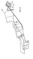
- FIG. 6 is a side view showing the rear fender in which the tail lamp structure for a motorcycle according to the embodiment of the present invention is disposed.
- FIG. 7 is an exploded side view showing the rear fender in which the tail lamp structure for a motorcycle according to the embodiment of the present invention is disposed and another rear fender.
- FIG. 8 is a plan view showing a rear winker mounted to the rear fender in which the tail lamp structure for a motorcycle according to the embodiment of the present invention is disposed.
- FIG. 9 is a plan view of a rear reflector mounted to the rear fender in which the tail lamp structure for a motorcycle according to the embodiment of the present invention is disposed.
- FIG. 10 is a partial sectional plan view showing a state that the rear fender in which the tail lamp structure for a motorcycle according to the embodiment of the present invention is disposed is connected to another rear fender by using the rear winkers and the rear reflector.
- FIG. 11 is a side view showing a state that the rear fender in which the tail lamp structure for a motorcycle according to the embodiment of the present invention is disposed is fitted to another rear fender.
-
- It is to be noted that in the following description, an orientation of each component from front to rear, from left to right, or the like, is based on the running direction of a vehicular body.
- FIG. 1 is a side view showing an entire configuration of a motorcycle to which the tail lamp structure according to this embodiment is applied.
- A motorcycle 1 includes, as shown in FIG. 1, a
body frame 2. A pair of left and right front forkedportions 3 are turnably supported by a front end portion of thebody frame 2. A pair of left andright handlebars 4 for steering are mounted at upper ends of the front forkedportions 3 in such a manner as to be located at an upper front portion of a vehicular body. Afront wheel 5 is rotatably supported by the front forkedportions 3. An engine 6 is supported by thebody frame 2. Arear fork 8 is vertically swigably supported by a radiator 7 disposed in front of the engine 6, a rear end of the engine 6, and thebody frame 2. A rear wheel 9 is rotatably supported by a rear end portion of therear fork 8. Afuel tank 10 is disposed on an upper portion of the body frame 1. A main seat 11 for a driver and apillion seat 12 for a passenger are disposed behind thefuel tank 10. The front portion of the vehicular body is nearly covered with afront cowl 15. In addition, thepillion seat 12 is disposed on arear cowl 13 provided behind the driver's seat 11. - The
body frame 2 includes ahead pipe 16, a pair of left and rightmain frames 17, a pair of left andright connection plates 19, and a pair of left andright seat rails 18. Thehead pipe 16 is disposed at a front end of thebody frame 2. Themain frames 17 branched right and left from thehead pipe 16 extend rearwardly, obliquely downwardly therefrom. A frontside engine hanger 17a is integrally provided on a front portion of each of themain frames 17 in such a manner as to extend downwardly therefrom, and a rearside engine hanger 17b is integrally provided on a rear portion of themain frame 17 in such a manner as to extend downwardly. Theconnection plates 19 are connected to upper rear sides of themain frames 17. Theseat rails 18 are connected to themain frames 17 and theconnection plates 19 in such a manner as to extend rearwardly, obliquely upwardly. Theseat rails 18 have a pair of left and rightupper pipes 18a connected to theconnection plates 19 and extending rearwardly, obliquely upwardly therefrom, and a pair of left and rightlower pipes 18b connected to connectingportions 20 provided at rear ends of themain frames 17 and extending rearwardly, obliquely upwardly therefrom. Rear ends of theupper pipes 18a and thelower pipes 18b are welded to each other. A front end portion of therear cowl 13 is connected to the connectingportions 20 of themain frames 17. - The engine 6 is a parallel multi-cylinder/four-cycle engine including a
cylinder block 22 having acylinder head 21 and acrankcase 23 provided under thecylinder block 22 in such a manner as to be continuous therefrom, wherein a plurality of cylinders are disposed in parallel in the lateral direction in thecylinder block 22. The engine 6 is supported by thebody frame 2 in a state that thecylinder block 22 is slightly tilted forwardly. To support the engine 6, thecylinder block 22 is bolted on the frontside engine hangers 17a of themain frames 17, and an upper portion of a rear end of thecrankcase 23 is bolted on the rearside engine hangers 17b of themain frames 17. -
Exhaust pipes 25 are connected to a front portion of thecylinder block 22 in such a manner as to be communicated to respective cylinders (only oneexhaust pipe 25 is shown in FIG. 1). The plurality ofexhaust pipes 25 extend downwardly from end portions thereof connected to thecylinder block 22. Theexhaust pipes 25 are put in order under the engine 6, being bent to extend rearwardly along a back surface of thecrankcase 23, and are collected, under a rear portion of thecrankcase 23, into onecollecting pipe 26. Thecollecting pipe 26 is disposed on the right side of the rear wheel 9 while being raised rightwardly, obliquely rearwardly. - The
rear fork 8 has, at its front end, a base portion 30 from which a pair of left and right forkedportions 31 extend rearwardly. The base portion 30 is pivotably supported by apivot 6A provided at a rear end portion of the engine 6, whereby therear fork 8 is vertically swingable around thepivot 6A. Arear cushion unit 32 for relieving and absorbing vibration applied from a road surface to the rear wheel 9 is interposed between the base portion 30 of therear fork 8 and rear ends of themain frames 17. Arear fender 33 for covering an upper front portion of the rear wheel 9 is mounted to upper portions of the forkedportions 31. A rear fender (first rear fender) 34 for covering an upper intermediate portion of the rear wheel 9 is mounted to a lower portion of therear cowl 13. A rear fender (second rear fender) 35 for covering an upper rear portion of the rear wheel 9 is mounted to a rear portion of therear fender 34. - A pair of left and right front winkers 36 are mounted to the
front cowl 15, and a pair of left and rightrear winkers 37 are mounted to a boundary portion between therear fender 34 and therear fender 35. - A tail lamp unit to which the tail lamp structure according to this embodiment is applied and a peripheral portion of the tail lamp unit will be described below.
- A
tail lamp unit 40 according to this embodiment is, as shown in FIGS. 2 and 3, disposed inside a space surrounded by a rear end portion of therear cowl 13 and a rear end portion of therear fender 34 disposed under therear cowl 13. The rear end portion of therear cowl 13 is, as will be fully described below, formed into a shape having a lateral width becoming narrow as nearing to an upper side leading end of therear cowl 13. - The rear end portion of the
rear cowl 13, which covers the upper side of thetail lamp unit 40, has such a taper shape as described below. As seen from the rear side (see FIG. 2), the lateral width of the rear end portion of therear cowl 13 becomes narrow as nearing to an upper side leading end of therear cowl 13; as seen from the upper side (see FIG. 4), the lateral width of the rear end portion of therear cowl 13 becomes narrow as nearing to a rear side leading end of therear cowl 13; and as seen from the left or right side (see FIG. 3), the lateral width of the rear end portion of therear cowl 13 becomes thin as nearing to a rear side leading end of therear cowl 13. As shown in FIG. 4, therear cowl 13 has two mountingportions 42 located on left and right sides of a longitudinally intermediate portion of therear cowl 13. - The rear end portion of the
rear fender 34 covers, as shown in FIGS. 2 and 3, the lower side of thetail lamp unit 40. As seen from the upper side (see FIG. 5), the rear end portion of therear fender 34 has a taper shape becoming thinner as becoming closer to a rear side leading end of therear fender 34. As shown in FIG. 5, therear fender 34 has two mountingportions 43 located on left and right sides of a longitudinally intermediate portion of therear fender 34. In a state that therear fender 34 is disposed under therear cowl 13, the mountingportions 43 of therear fender 34 are mounted to the mountingportions 42 of therear cowl 13 by means of small screws or the like. - As shown in FIG. 3, the
tail lamp unit 40, which is disposed in a space surrounded by the rear end portions of therear cowl 13 and therear fender 34, has alamp holding portion 45 provided on a front portion and alamp cover 46 mounted on a rear side of thelamp holding portion 45. Thelamp cover 46 has a taper shape matched with the taper shape of therear cowl 13. Concretely, as seen from the rear side (see FIG. 2), a lateral width of thelamp cover 46 becomes narrow as nearing to an upper side leading end of thelamp cover 46; and as seen from the left or right side (see FIG. 3), the lateral width of thelamp cover 46 becomes narrow as nearing to a rear side leading end of thelamp cover 46. - As shown in FIGS. 2 and 3, the
lamp cover 46 is divided into an upper portion and a lower portion. A horizontally-elongatedtail lamp portion 47 is disposed on the upper portion of thelamp cover 46, and a horizontally-elongatedbrake lamp portion 48 is disposed under thetail lamp portion 47. Thetail lamp portion 47 lights up for signifying the presence of the motorcycle 1 to a vehicle running behind the motorcycle 1, and thebrake lamp portion 48 lights up for signifying, at the time of braking operation of the motorcycle 1, the on-state of braking to a vehicle running behind the motorcycle 1. - The
lamp holding portion 45 includes only one row of a plurality of LEDs (Light Emitting Diodes) 50 arrayed on the lateral direction. TheLEDs 50, which are used for making thetail lamp portion 47 light up, are located in thetail lamp portion 47 provided on the upper portion of thelamp cover 46. Thelamp holding portion 45 also includes a plurality of vertical rows each having a plurality ofLEDs 51 arrayed on the lateral direction. TheLEDs 51, which are used for making thebrake lamp portion 48 light up, are located in thebrake lamp portion 48 provided on the lower portion of thelamp cover 46. - The
rear fender 34 has, on the lower side of a rear end portion, a mountingportion 54. A mountingportion 52 of therear fender 35 shown in FIG. 7, the left and rightrear winkers 37 shown in FIG. 8, and arear reflector 53 shown in FIG. 9 are mounted to the mountingportion 54 of therear fender 34. As shown in FIGS. 6 and 7, the mountingportion 54 has a pair of left andright hole portions 56 passing through the mountingportion 54 in the lateral direction. The mountingportion 54 also has, at positions behind thehole portions 56, a pair of left andright hole portions 57 passing through the mountingportion 54 in the lateral direction, wherein thehole portions 57 have diameters smaller than those of thehole portions 56. As shown in FIG. 2, the mountingportion 54 further includes, at its rear portion, ahole portion 58 and ahole portion 59 having a diameter smaller than that of thehole portion 58, which holes are adjacent to each other in the lateral direction and pass through the mountingportion 54 in the longitudinal direction. - The mounting
portion 52 of therear fender 35 shown, for example, in FIG. 7 is fitted to the outer side of the mountingportion 54 of therear fender 34. As shown in FIG. 10, the mountingportion 52 has a pair of left andright hole portions 60 having the same diameters as those of thehole portions 56 on therear fender 34 side and also a pair of left andright portions 61 having the same diameters as those of thehole portions 57 on therear fender 34 side. When the mountingportion 52 of therear fender 35 is fitted to the mountingportion 54 of therear fender 34, thehole portions 60 on therear fender 35 side are disposed coaxially with thehole portions 56 on therear fender 34 side and thehole portions 61 on therear fender 35 side are disposed coaxially with thehole portions 57 on therear fender 34 side. The mountingportion 52 of therear fender 35 also has ahole portion 62 having the same diameter as that of thehole portion 58 on therear fender 34 side, and also ahole portion 63 having the same diameter as that of thehole portion 59 on therear fender 34 side. When the mountingportion 52 of therear fender 35 is fitted to the mountingportion 54 of therear fender 34, thehole portion 62 on therear fender 35 side is disposed coaxially with thehole portion 58 on therear fender 34 side, and thehole portion 63 on therear fender 35 side is disposed coaxially with thehole portion 59 on therear fender 34 side. - As shown in FIG. 8, each of the
rear winkers 37 has a rear winkermain body 65 having alight emission portion 64. A positioning/fitting portion 66 is provided on the front side of a side portion of the rear winkermain body 65. The positioning/fitting portion 66 has a diameter slightly smaller than that of each of the large-diameter hole portion 56 of therear fender 34 and the large-diameter hole portion 60 of therear fender 35. Awiring line 68 is inserted in the positioning/fitting portion 66. Ascrew shaft portion 67 is provided on the rear winkermain body 65 at a position behind the positioning/fitting portion 66. Thescrew shaft portion 67 has a diameter slightly smaller than that of each of the small-diameter hole portion 57 of therear fender 34 and the small-diameter hole portion 61 of therear fender 35. - As shown in FIG. 9, the
rear reflector 53 has a plate-shaped rear reflectormain body 70 having on its one side a reflectingportion 69, ascrew shaft portion 71 projecting from a central portion of the rear reflectormain body 70, and apositioning pin 72 provided adjacently to thescrew shaft portion 71. Thescrew shaft portion 71 has a diameter slightly smaller than that of each of thehole portion 58 of therear fender 34 and thehole portion 62 of therear fender 35. Thepositioning pin 72 has a diameter slightly smaller than that of each of thehole portion 59 of therear fender 34 and thehole portion 63 of therear fender 35. - Each of the left and right
rear winkers 37 is mounted to therear fender 34 and therear fender 35 as follows. First, as shown in FIG. 11, the mountingportion 52 of therear fender 35 is fitted to the mountingportion 54 of therear fender 34. In this state, as shown in FIG. 10, the positioning/fitting portion 66 of therear winker 37 is fitted in the frontside hole portion 60 of therear fender 35 and at the same time thewiring line 68 extending from the inside of the positioning/fitting portion 66 is inserted in thehole portion 56 of therear fender 34 and thehole portion 60 of therear fender 35; thescrew shaft portion 67 is inserted in the rearside hole portion 57 of therear fender 34 and the rearside hole portion 61 of therear fender 35; and anut member 74 is screwed with a projecting leading end of thescrew shaft portion 67 via awasher member 73, whereby therear fender 34 and therear fender 35 are clamped by means of the rear winkermain body 65 and thenut member 74. - On the other hand, the
screw shaft portion 71 of therear reflector 53 is inserted in thehole portion 58 of therear fender 34 and thehole portion 62 of therear fender 35; thepositioning pin 72 of therear reflector 53 is fitted in thehole portion 63 of therear fender 35; and anut member 77 is screwed with a projecting leading end of thescrew shaft portion 71 via awasher member 76, whereby therear fender 34 and therear fender 35 are clamped by means of the rear reflectormain body 70 and thenut member 77. - In this way, the left and right
rear winkers 37 and therear reflector 53 are mounted to therear fender 34 and therear fender 35. At the same time, therear fender 35 is mounted to therear fender 34. To be more specific, therear fender 35 extending downwardly from the rear end portion of therear fender 34 is mounted to therear fender 34 for covering the lower side of therear cowl 13 by means of the left and rightrear winkers 37 and therear reflector 53. - In this embodiment, the diameter of the
hole portion 56 of therear fender 34 is the same as that of thehole portion 60, disposed coaxially with thehole portion 56, of therear fender 35; the diameter of thehole portion 57 of therear fender 34 is the same as that of thehole portion 61, disposed coaxially with thehole portion 57, of therear fender 35; the diameter of thehole portion 58 of therear fender 34 is the same as that of thehole portion 62, disposed coaxially with thehole portion 58, of therear fender 35; and thehole portion 59 of therear fender 34 is the same as that of thehole portion 63, disposed coaxially with thehole portion 59, of therear fender 35. Accordingly, even if therear fender 35 is not mounted to therear fender 34, the left andright winkers 37 can be mounted via thehole portions portion 34 of therear fender 34, and therear reflector 53 can be mounted via thehole portions rear fender 34, whereby the structure can be easily changed into a racing structure with norear fender 35. - According to the tail lamp structure for the motorcycle 1 in this embodiment, as shown in FIG. 2, since the
tail lamp portion 47 is disposed on the upper portion of the tail lamp structure and thebrake lamp portion 48 is disposed under thetail lamp portion 47, even if the tail lamp structure is disposed inside the rear end portion of therear cowl 13, which portion has a shape whose lateral width becomes narrow as nearing to the upper end of therear cowl 13, the lighting area of thebrake lamp portion 48 does not become small. As a result, it is possible to ensure a sufficient lighting area of thebrake lamp portion 48. - As described above, according to the tail lamp structure for a motorcycle of the present invention, since a tail lamp portion is disposed on an upper portion of the tail lamp structure and a brake lamp portion is disposed under the tail lamp portion, even if the tail lamp structure is disposed inside the rear end portion of a rear cowl, which portion has a shape whose lateral width becomes narrow as nearing to the upper end of the rear cowl, the lighting area of the brake lamp portion does not become small. As a result, it is possible to ensure a sufficient lighting area of the brake lamp portion.
- In summary it is an object to provide a tail lamp structure for a motorcycle, which is capable of sufficiently ensuring a lighting area of a brake lamp even if the tail lamp structure is disposed inside a rear end portion of a rear cowl, which portion has a shape whose lateral width becomes narrow as nearing to an upper end of the rear cowl.
To achieve this, atail lamp unit 40 is disposed inside a rear end portion of arear cowl 13, which portion has a shape whose lateral width becomes narrow as nearing to an upper end of therear cowl 13. Atail lamp 47 is disposed on an upper portion of the tail lamp structure and abrake lamp 48 is disposed under thetail lamp 47, whereby a sufficient lighting area of the brake lamp can be ensured.
Claims (1)
- A tail lamp structure (40) for a motorcycle (1), which is disposed inside a rear end portion of a rear cowl (13), said rear end portion having a shape whose lateral width becomes narrow as nearing to an upper end of said rear cowl (13), characterized in that
a tail lamp (47) is disposed on an upper portion of said tail lamp structure (40), and a brake lamp (48) is disposed under said tail lamp(47).
Applications Claiming Priority (2)
| Application Number | Priority Date | Filing Date | Title |
|---|---|---|---|
| JP2001250576 | 2001-08-21 | ||
| JP2001250576A JP4083402B2 (en) | 2001-08-21 | 2001-08-21 | Motorcycle taillight structure |
Publications (2)
| Publication Number | Publication Date |
|---|---|
| EP1285847A1 true EP1285847A1 (en) | 2003-02-26 |
| EP1285847B1 EP1285847B1 (en) | 2007-11-28 |
Family
ID=19079366
Family Applications (1)
| Application Number | Title | Priority Date | Filing Date |
|---|---|---|---|
| EP02013760A Expired - Fee Related EP1285847B1 (en) | 2001-08-21 | 2002-06-20 | Tail lamp structure for motorcycle |
Country Status (8)
| Country | Link |
|---|---|
| US (1) | US6793384B2 (en) |
| EP (1) | EP1285847B1 (en) |
| JP (1) | JP4083402B2 (en) |
| KR (2) | KR100569166B1 (en) |
| CN (1) | CN1403328B (en) |
| BR (1) | BR0203149B1 (en) |
| DE (1) | DE60223764T2 (en) |
| TW (1) | TW593040B (en) |
Cited By (3)
| Publication number | Priority date | Publication date | Assignee | Title |
|---|---|---|---|---|
| EP1422132A2 (en) * | 2002-11-22 | 2004-05-26 | HONDA MOTOR CO., Ltd. | Tail lamp for vehicle |
| EP2301802A1 (en) * | 2009-09-16 | 2011-03-30 | Honda Motor Co., Ltd. | Structure of rear lighting device for motorcycle |
| DE102005048387B4 (en) * | 2004-10-12 | 2015-09-10 | Honda Motor Co., Ltd. | Tail light assembly for vehicles |
Families Citing this family (22)
| Publication number | Priority date | Publication date | Assignee | Title |
|---|---|---|---|---|
| JP2004090881A (en) * | 2002-09-04 | 2004-03-25 | Yamaha Motor Co Ltd | Tail lamp device for motorcycle |
| US7073618B1 (en) * | 2003-07-01 | 2006-07-11 | Polaris Industries Inc. | Flush mounted taillight |
| JP4339050B2 (en) | 2003-09-04 | 2009-10-07 | 本田技研工業株式会社 | Motorcycle taillight device |
| JP4555719B2 (en) | 2005-03-30 | 2010-10-06 | 本田技研工業株式会社 | Motorcycle rear lighting structure |
| JP2008024289A (en) * | 2006-06-23 | 2008-02-07 | Yamaha Motor Co Ltd | Motorcycle |
| JP4707112B2 (en) * | 2006-09-08 | 2011-06-22 | 本田技研工業株式会社 | Motorcycle rear lighting system |
| JP2008162511A (en) * | 2006-12-28 | 2008-07-17 | Yamaha Motor Co Ltd | Straddle type vehicle |
| US7669682B2 (en) | 2007-01-17 | 2010-03-02 | Polaris Industries Inc. | Rear suspension for a two wheeled vehicle |
| US7748746B2 (en) | 2007-01-17 | 2010-07-06 | Polaris Industries Inc. | Fuel tank arrangement for a vehicle |
| JP2009056950A (en) * | 2007-08-31 | 2009-03-19 | Honda Motor Co Ltd | Reflector support structure |
| JP5090838B2 (en) * | 2007-09-21 | 2012-12-05 | 川崎重工業株式会社 | Motorcycle rear fender assembly |
| US20090122566A1 (en) * | 2007-11-13 | 2009-05-14 | Glen Cunningham | Vehicle tail light assembly and method of use |
| US8985814B2 (en) | 2007-12-13 | 2015-03-24 | Valeo North America, Inc. | Dynamic three dimensional effect lamp assembly |
| FR2928110B1 (en) * | 2008-03-03 | 2010-06-11 | Valeo Vision | OPTICAL SYSTEM WITH MAIN FUNCTION FOR MOTOR VEHICLE |
| EP2261555B1 (en) | 2008-03-06 | 2014-10-15 | Honda Motor Co., Ltd. | Taillight unit |
| JP2012071644A (en) | 2010-09-28 | 2012-04-12 | Yamaha Motor Co Ltd | Motorcycle |
| JP5875435B2 (en) * | 2012-03-28 | 2016-03-02 | 本田技研工業株式会社 | Motorcycle taillight device |
| JP6426577B2 (en) * | 2015-09-30 | 2018-11-21 | 本田技研工業株式会社 | Rear combination lamp for vehicle and vehicle |
| JP6381081B2 (en) * | 2016-09-30 | 2018-08-29 | 本田技研工業株式会社 | Vehicle lighting equipment |
| US10300973B2 (en) | 2017-08-14 | 2019-05-28 | Bernard Luttmer | Taillight assembly for a motorcycle |
| IT202000016990A1 (en) | 2020-07-13 | 2022-01-13 | Vincenzo Maresca | MOTORCYCLE SEAT COVER EQUIPPED WITH MULTIFUNCTION ELECTRONIC UNIT |
| US11623560B2 (en) | 2021-08-03 | 2023-04-11 | XKGlow, Inc. | Replaceable vehicle light |
Citations (3)
| Publication number | Priority date | Publication date | Assignee | Title |
|---|---|---|---|---|
| FR732465A (en) * | 1932-02-29 | 1932-09-21 | Signaling device or apparatus for vehicles, mainly for bicycles | |
| JPH05278655A (en) * | 1992-04-03 | 1993-10-26 | Suzuki Motor Corp | Rear combination lamp mounting device for motorcycle |
| JPH0840329A (en) * | 1994-07-29 | 1996-02-13 | Suzuki Motor Corp | Tail lamp mounting structure for motorcycle |
Family Cites Families (8)
| Publication number | Priority date | Publication date | Assignee | Title |
|---|---|---|---|---|
| JPS5973334A (en) * | 1982-10-19 | 1984-04-25 | Honda Motor Co Ltd | Tail light apparatus |
| JPH03193580A (en) * | 1989-12-25 | 1991-08-23 | Suzuki Motor Corp | Rear spoiler for motor scooter |
| JP2969524B2 (en) * | 1990-01-26 | 1999-11-02 | ヤマハ発動機株式会社 | Motorcycle carrier |
| JP3289782B2 (en) * | 1992-02-07 | 2002-06-10 | 本田技研工業株式会社 | Motorcycle stop lamp |
| JP3516403B2 (en) * | 1992-11-27 | 2004-04-05 | 本田技研工業株式会社 | Motorcycle lamp arrangement |
| JPH06191451A (en) * | 1992-12-24 | 1994-07-12 | Honda Motor Co Ltd | Taillight installing structure of motor-bicycle |
| JPH06298145A (en) | 1993-04-19 | 1994-10-25 | Suzuki Motor Corp | Rear fender of motorcycle |
| US6257362B1 (en) * | 1999-07-28 | 2001-07-10 | Harley-Davidson Motor Company | Motorcycle fender mounting system |
-
2001
- 2001-08-21 JP JP2001250576A patent/JP4083402B2/en not_active Expired - Fee Related
-
2002
- 2002-06-20 DE DE60223764T patent/DE60223764T2/en not_active Expired - Lifetime
- 2002-06-20 EP EP02013760A patent/EP1285847B1/en not_active Expired - Fee Related
- 2002-07-02 KR KR1020020037960A patent/KR100569166B1/en not_active IP Right Cessation
- 2002-07-04 TW TW091114824A patent/TW593040B/en not_active IP Right Cessation
- 2002-08-08 BR BRPI0203149-3A patent/BR0203149B1/en not_active IP Right Cessation
- 2002-08-08 CN CN021277540A patent/CN1403328B/en not_active Expired - Fee Related
- 2002-08-09 US US10/214,710 patent/US6793384B2/en not_active Expired - Fee Related
-
2006
- 2006-02-02 KR KR1020060010191A patent/KR100652522B1/en not_active IP Right Cessation
Patent Citations (3)
| Publication number | Priority date | Publication date | Assignee | Title |
|---|---|---|---|---|
| FR732465A (en) * | 1932-02-29 | 1932-09-21 | Signaling device or apparatus for vehicles, mainly for bicycles | |
| JPH05278655A (en) * | 1992-04-03 | 1993-10-26 | Suzuki Motor Corp | Rear combination lamp mounting device for motorcycle |
| JPH0840329A (en) * | 1994-07-29 | 1996-02-13 | Suzuki Motor Corp | Tail lamp mounting structure for motorcycle |
Non-Patent Citations (2)
| Title |
|---|
| PATENT ABSTRACTS OF JAPAN vol. 018, no. 056 (M - 1551) 28 January 1994 (1994-01-28) * |
| PATENT ABSTRACTS OF JAPAN vol. 1996, no. 06 28 June 1996 (1996-06-28) * |
Cited By (5)
| Publication number | Priority date | Publication date | Assignee | Title |
|---|---|---|---|---|
| EP1422132A2 (en) * | 2002-11-22 | 2004-05-26 | HONDA MOTOR CO., Ltd. | Tail lamp for vehicle |
| EP1422132A3 (en) * | 2002-11-22 | 2006-08-30 | HONDA MOTOR CO., Ltd. | Tail lamp for vehicle |
| DE102005048387B4 (en) * | 2004-10-12 | 2015-09-10 | Honda Motor Co., Ltd. | Tail light assembly for vehicles |
| EP2301802A1 (en) * | 2009-09-16 | 2011-03-30 | Honda Motor Co., Ltd. | Structure of rear lighting device for motorcycle |
| US8342724B2 (en) | 2009-09-16 | 2013-01-01 | Honda Motor Co., Ltd. | Rear lighting device for a vehicle |
Also Published As
| Publication number | Publication date |
|---|---|
| JP4083402B2 (en) | 2008-04-30 |
| DE60223764T2 (en) | 2008-04-10 |
| US6793384B2 (en) | 2004-09-21 |
| US20030063472A1 (en) | 2003-04-03 |
| KR20060018277A (en) | 2006-02-28 |
| BR0203149A (en) | 2003-05-06 |
| TW593040B (en) | 2004-06-21 |
| JP2003054460A (en) | 2003-02-26 |
| DE60223764D1 (en) | 2008-01-10 |
| EP1285847B1 (en) | 2007-11-28 |
| KR100652522B1 (en) | 2006-12-01 |
| BR0203149B1 (en) | 2012-09-04 |
| KR100569166B1 (en) | 2006-04-07 |
| CN1403328A (en) | 2003-03-19 |
| CN1403328B (en) | 2011-08-03 |
| KR20030047676A (en) | 2003-06-18 |
Similar Documents
| Publication | Publication Date | Title |
|---|---|---|
| EP1285847B1 (en) | Tail lamp structure for motorcycle | |
| CN1296247C (en) | Motorcycle and rear car body structure of said motor cycle | |
| EP2055618B1 (en) | Motorcycle with a seat rail | |
| EP1332957B1 (en) | Vehicle taillight | |
| EP3277563B1 (en) | Lighting device structure including auxiliary illumination | |
| JP5335760B2 (en) | Motorcycle lighting equipment | |
| US10793214B1 (en) | Headlight support structure of saddle riding vehicle | |
| US11407464B2 (en) | Front structure of saddle riding vehicle | |
| EP1428745B1 (en) | Rear view mirror assembly | |
| EP1816393A1 (en) | Lighting device | |
| WO2017018331A1 (en) | Saddled vehicle | |
| CN107709146B (en) | Inner rear mudguard structure of motorcycle | |
| US6939028B2 (en) | Rear lighting device for motorcycles | |
| JP4545325B2 (en) | Motorcycle headlight device | |
| JP2009173220A (en) | Lamp unit arrangement structure for saddle-riding type vehicle | |
| JP4509401B2 (en) | Lamp mounting structure for tail cowl of motorcycle | |
| JP4145620B2 (en) | Small vehicle | |
| CN101376353B (en) | Illuminator for motorcycle | |
| JPH03220035A (en) | Motorcycle | |
| JP2022149091A (en) | Saddle-riding type vehicle | |
| JP2006273089A (en) | Light structure and light mounting method |
Legal Events
| Date | Code | Title | Description |
|---|---|---|---|
| PUAI | Public reference made under article 153(3) epc to a published international application that has entered the european phase |
Free format text: ORIGINAL CODE: 0009012 |
|
| AK | Designated contracting states |
Kind code of ref document: A1 Designated state(s): AT BE CH CY DE DK ES FI FR GB GR IE IT LI LU MC NL PT SE TR |
|
| AX | Request for extension of the european patent |
Extension state: AL LT LV MK RO SI |
|
| 17P | Request for examination filed |
Effective date: 20030305 |
|
| AKX | Designation fees paid |
Designated state(s): DE GB IT |
|
| 17Q | First examination report despatched |
Effective date: 20060201 |
|
| GRAP | Despatch of communication of intention to grant a patent |
Free format text: ORIGINAL CODE: EPIDOSNIGR1 |
|
| RAP1 | Party data changed (applicant data changed or rights of an application transferred) |
Owner name: HONDA GIKEN KOGYO KABUSHIKI KAISHA |
|
| GRAS | Grant fee paid |
Free format text: ORIGINAL CODE: EPIDOSNIGR3 |
|
| GRAA | (expected) grant |
Free format text: ORIGINAL CODE: 0009210 |
|
| AK | Designated contracting states |
Kind code of ref document: B1 Designated state(s): DE GB IT |
|
| REF | Corresponds to: |
Ref document number: 60223764 Country of ref document: DE Date of ref document: 20080110 Kind code of ref document: P |
|
| PLBE | No opposition filed within time limit |
Free format text: ORIGINAL CODE: 0009261 |
|
| STAA | Information on the status of an ep patent application or granted ep patent |
Free format text: STATUS: NO OPPOSITION FILED WITHIN TIME LIMIT |
|
| 26N | No opposition filed |
Effective date: 20080829 |
|
| REG | Reference to a national code |
Ref country code: GB Ref legal event code: 746 Effective date: 20140128 |
|
| REG | Reference to a national code |
Ref country code: DE Ref legal event code: R084 Ref document number: 60223764 Country of ref document: DE Effective date: 20140204 |
|
| PGFP | Annual fee paid to national office [announced via postgrant information from national office to epo] |
Ref country code: IT Payment date: 20140623 Year of fee payment: 13 |
|
| PGFP | Annual fee paid to national office [announced via postgrant information from national office to epo] |
Ref country code: DE Payment date: 20150616 Year of fee payment: 14 Ref country code: GB Payment date: 20150617 Year of fee payment: 14 |
|
| PG25 | Lapsed in a contracting state [announced via postgrant information from national office to epo] |
Ref country code: IT Free format text: LAPSE BECAUSE OF NON-PAYMENT OF DUE FEES Effective date: 20150620 |
|
| REG | Reference to a national code |
Ref country code: DE Ref legal event code: R119 Ref document number: 60223764 Country of ref document: DE |
|
| GBPC | Gb: european patent ceased through non-payment of renewal fee |
Effective date: 20160620 |
|
| PG25 | Lapsed in a contracting state [announced via postgrant information from national office to epo] |
Ref country code: DE Free format text: LAPSE BECAUSE OF NON-PAYMENT OF DUE FEES Effective date: 20170103 |
|
| PG25 | Lapsed in a contracting state [announced via postgrant information from national office to epo] |
Ref country code: GB Free format text: LAPSE BECAUSE OF NON-PAYMENT OF DUE FEES Effective date: 20160620 |