EP1288098A1 - Wheel sensor - Google Patents
Wheel sensor Download PDFInfo
- Publication number
- EP1288098A1 EP1288098A1 EP02090264A EP02090264A EP1288098A1 EP 1288098 A1 EP1288098 A1 EP 1288098A1 EP 02090264 A EP02090264 A EP 02090264A EP 02090264 A EP02090264 A EP 02090264A EP 1288098 A1 EP1288098 A1 EP 1288098A1
- Authority
- EP
- European Patent Office
- Prior art keywords
- coils
- coil
- track
- wheel
- wheel sensor
- Prior art date
- Legal status (The legal status is an assumption and is not a legal conclusion. Google has not performed a legal analysis and makes no representation as to the accuracy of the status listed.)
- Granted
Links
Images


Classifications
-
- B—PERFORMING OPERATIONS; TRANSPORTING
- B61—RAILWAYS
- B61L—GUIDING RAILWAY TRAFFIC; ENSURING THE SAFETY OF RAILWAY TRAFFIC
- B61L1/00—Devices along the route controlled by interaction with the vehicle or vehicle train, e.g. pedals
- B61L1/16—Devices for counting axles; Devices for counting vehicles
- B61L1/163—Detection devices
- B61L1/165—Electrical
Landscapes
- Engineering & Computer Science (AREA)
- Automation & Control Theory (AREA)
- Mechanical Engineering (AREA)
- Investigating Or Analyzing Materials By The Use Of Magnetic Means (AREA)
- Arrangements For Transmission Of Measured Signals (AREA)
- Measuring Fluid Pressure (AREA)
- Train Traffic Observation, Control, And Security (AREA)
- Pinball Game Machines (AREA)
- Vehicle Body Suspensions (AREA)
- Transmission And Conversion Of Sensor Element Output (AREA)
- Electric Propulsion And Braking For Vehicles (AREA)
Abstract
Description
Die Erfindung betrifft einen Radsensor sowie eine Radsensoranordnung
gemäß dem Oberbegriff der nebengeordneten Ansprüche
1, 3, 8 und 10. Radsensoren werden im Bahnwesen für die
Gleisfreimeldung, aber auch für andere Schalt- und Meldeaufgaben
eingesetzt. Dabei wird überwiegend die magnetfeldbeeinflussende
Wirkung der Eisenräder der Schienenfahrzeuge ausgenutzt.
Mittels am Gleiskörper angebrachter induktiver Sensoren,
die ein spezifisches Magnetfeld erzeugen, lässt sich die
Rückwirkung der Eisenräder erfassen, wobei mit jeder Raderfassung
bzw. Achsenerfassung ein Radimpuls registriert wird.
Die Anzahl der Radimpulse gibt im Zusammenwirken mit einem
weiteren Radsensor Auskunft über den Belegungszustand des dazwischenliegenden
Gleisabschnittes. Diese Gleisfreimeldung
stellt ein wesentliches Entscheidungskriterium für die Steuerung
von Weichen und Signalen dar. Anhand des Belegungszustandes
von Gleisabschnitten wird die Entscheidung getroffen,
ob ein Schienenfahrzeug in diesem Gleisabschnitt einfahren
darf oder nicht. Folglich müssen die Meldesignale der Achszähler
extrem hohen Zuverlässigkeitsanforderungen genügen. Es
ist sicherzustellen, dass nur die die Sensoren überfahrenden
Eisenräder der Schienenfahrzeuge von den Sensoren erfasst
werden und Störmagnetfelder anderer Herkunft ignoriert werden.
Das betrifft beispielsweise Magnetfelder, die bei elektrischer
Traktion durch Schienenströme und durch Fahrzeugkomponenten
wie Transformatoren, Drosseln und elektronische
Schienenbremsen entstehen. Letztere stellen ein besonderes
Problem dar, da die erzeugten Magnetfelder sehr stark sind.
Das betrifft insbesondere die für den ICE (Intercity Express)
entwickelte Wirbelstrombremse, welche in erregtem Zustand ein
Störmagnetfeld erzeugt, das das Arbeitsmagnetfeld des induktiven
Sensors sehr stark überlagert.The invention relates to a wheel sensor and a wheel sensor arrangement
according to the preamble of the
Ein Lösungsansatz, der darauf beruht, die Arbeitsfrequenzen der Sensoren in vermeintlich störfeldfrequenzfreie Größenordnungen zu legen, kann keinen dauerhaften Erfolg garantieren, da durch die Entwicklung neuer Fahrzeugkomponenten ständig neue Störfelder mit teilweise sehr hohen Frequenzen hinzukommen. Durch Frequenzwahl lässt sich außerdem nicht vermeiden, dass Störfelder Frequenzanteile im Bereich der Arbeitsfrequenz des induktiven Sensors enthalten. Üblicher Weise liegen die Arbeitsfrequenzen im Bereich von 30 kHz bis 1 MHz, während Störfelder durchaus auch Frequenzen bis zu 2 MHz erreichen können.A solution based on the working frequencies of the sensors in magnitudes that are supposed to be free of interference field frequencies laying cannot guarantee lasting success, because of the development of new vehicle components new interference fields with sometimes very high frequencies are added. Frequency selection also cannot avoid that interference fields frequency components in the range of the working frequency of the inductive sensor included. Usually lie the working frequencies in the range from 30 kHz to 1 MHz, while Interference fields can also reach frequencies up to 2 MHz can.
Ein anderer Lösungsansatz basiert auf Kompensationsbestrebungen der Art, dass das Störmagnetfeld durch Aufbau eines gegensinnigen Feldes quasi neutralisiert wird. Gemäß der DE-A1-197 09 844 ist dazu eine Spulenanordnung mit einem magnetischen Kern vorgesehen. Zwei konzentrisch zueinander angeordnete Spulen sind derart geschaltet, dass bei gemeinsamer Beströmung gegensinnige Magnetfelder entstehen. Ein magnetisches Störfeld induziert hingegen in beiden Spulen Störspannungen, die sich wegen der gegensinnigen Beschaltung der beiden Spulen kompensieren. -Die Spulenanordnung ist Teil eines induktiven Sensors zum Erzeugen eines Arbeitsmagnetfeldes erhalten bleibt. Die Eisenmasse eines überfahrenden Rades verändert die Eigenschaften des Arbeitsmagnetfeldes, was sensorisch erfasst wird. Problematisch bei diesem Lösungsansatz ist jedoch, dass ein sehr starkes Störmagnetfeld, beispielsweise das einer erregten Wirbelstrombremse, den Spulenkern so magnetisieren kann, dass ein unerwünschtes Ansprechen des Sensors verursacht wird.Another approach is based on compensation efforts the way that the interference magnetic field by building an opposing Field is virtually neutralized. According to the DE-A1-197 09 844 is a coil arrangement with a magnetic Core provided. Two concentrically arranged Coils are switched so that when shared Magnetic fields flow in opposite directions. A magnetic one In contrast, interference field induces interference voltages in both coils, because of the opposite connection of the two Compensate coils. -The coil assembly is part of one Get inductive sensor for generating a working magnetic field remains. The iron mass of a wheel running over changes the properties of the working magnetic field, what is sensory is recorded. Problematic with this approach is, however, that a very strong interference magnetic field, for example that of an excited eddy current brake, the coil core like that can magnetize that an unwanted response of the Sensor is caused.
Eine ähnliche, aber kernlose Spulenanordnung ist aus der DE-A1-199 15 597 bekannt. Die Empfindlichkeit dieses gattungsbildenden Achszählers ist jedoch gering, da das zur Detektion des Rades erzeugte Magnetfeld den Bereich des Spurkranzes des Rades nicht optimal durchsetzt. Außerdem kann Nässe am Sensorgehäuse bei den üblicherweise hohen Arbeitsfrequenzen kernloser Spulenanordnungen zu einer weiteren Herabsetzung der Sensorempfindlichkeit führen.A similar but coreless coil arrangement is from the DE-A1-199 15 597 known. The sensitivity of this generic Axle counter is low, however, because of the detection magnetic field of the wheel created the area of the flange of the wheel does not penetrate optimally. Besides, can Wetness on the sensor housing at the usually high working frequencies coreless coil arrangements for a further reduction sensor sensitivity.
Der Erfindung liegt die Aufgabe zugrunde, diese Nachteile zu beseitigen und einen Radsensor mit induktivem Sensor anzugeben, dessen Parameter hinsichtlich der Empfindlichkeit und damit hinsichtlich der Zuverlässigkeit des Gesamtsystems optimiert sind.The object of the invention is to overcome these disadvantages eliminate and specify a wheel sensor with inductive sensor, its parameters in terms of sensitivity and thus with regard to the reliability of the overall system are optimized.
Die Aufgabe wird alternativ durch die kennzeichnenden Merkmale
der Ansprüche 1 und 3 gelöst. Gemäß Anspruch 1 wird eine
Optimierung erreicht, indem die innere Spule eine dem Flächenverhältnis
entsprechende höhere Windungszahl als die äußere
Spule aufweist. Auf diese Weise wird bei homogenen Störfeldern
nicht nur eine Teilkompensation derselben, sondern
eine vollständige Kompensation erreicht. Die spezielle Spulendimensionierung
hat außerdem zur Folge, dass die beim Befahren
in beiden Spulen entgegengesetzt auftretenden Induktionen
nicht gleich groß sind und folglich eine ausreichend hohe
Gesamtinduktion zur Detektion eines Rades verbleibt. Da
Störeffekte quasi vollständig eliminiert sind und das Arbeitsmagnetfeld
eine sehr hohe Feldstärke aufweist und den
Spurkranz des zu detektierenden Rades optimal durchsetzt, ergibt
sich gegenüber dem Stand der Technik eine wesentliche
Verbesserung der Empfindlichkeit der Sensorik und somit eine
Erhöhung der Zuverlässigkeit des Gesamtsystems. Ist das Störmagnetfeld
inhomogen, können Differenzen zwischen den Störspannungen
der Teilspulen Infolge der unterschiedlichen Spulenabmessungen
auftreten. In diesem Fall ist eine teilkompensierende
Wirkung vorhanden, wobei die effektiv verbleibende
Gesamtstörspannung äußerst gering und letztlich zu vernachlässigen
ist.The task is alternatively characterized by the characteristics
of
Die zweite Spule ist gemäß Anspruch 2 vorzugsweise zentrisch
innerhalb der ersten Spule angeordnet. Der Kompensationseffekt
ist jedoch auch dann vorhanden, wenn die innere Spule
exzentrisch angeordnet ist. Auch die Spulenformen können sehr
unterschiedlich sein. Beispielsweise kann die innere Spule
kreisförmige Windungen aufweisen und exzentrisch innerhalb
einer oval ausgebildeten äußeren Spule angeordnet sein.The second coil is preferably centric according to
Anspruch 3 charakterisiert eine weitere Lösung der Aufgabenstellung,
wobei gegenüber der Lösung gemäß Anspruch 1 zusätzlich
eine Vereinfachung erzielt wird. Spulen unterschiedlicher
Geometrie und unterschiedlicher Windungszahlen sind bei
dieser Alternativlösung nicht erforderlich. Statt dessen ist
eine in der Vertikalprojektion sich überlappende Anordnung
gleichartiger Spulen vorgesehen, wobei die Windungsebenen
quasi übereinander angeordnet sind. Da die Spulen nicht ineinander
oder sich durchdringend angeordnet sind, durchsetzt
das von einer Spule erzeugte Magnetfeld die andere Spule zu
gleichen Teilen mit entgegengerichteten inneren und äußeren
magnetischen Flüssen, das heißt, die Spulen sind magnetisch
voneinander entkoppelt.
Die Spulen sind nach Anspruch 4 vorzugsweise als sehr flache,
spiralförmig gewickelte Scheibenspulen ausgebildet. Auf diese
Weise lassen sich die Spulen problemlos in das Gehäuse eines
Radsensors einbauen.According to
Gemäß Anspruch 5 können die Windungsebenen der Spulen bei beiden Alternativlösungen parallel zur Gleisebene verlaufen.According to claim 5, the winding planes of the coils both alternative solutions run parallel to the track level.
Bei einer in Anspruch 6 gekennzeichneten speziellen Spulenanordnung
für die Alternativlösung gemäß Anspruch 3 sind beide
Spulen mit dem gleichen Neigungswinkel zu einer Horizontalfläche
in Gleisrichtung angekippt. Magnetische Störfelder
durchsetzen dann beide Spulen in gleicher Intensität und
Richtung und heben sich damit auf, auch wenn das Feld nicht
parallel zu den Spulenlängsachsen verläuft.In a special coil arrangement characterized in claim 6
for the alternative solution according to
Einfache Spulen- bzw. Wicklungsgeometrien, die auf einer runden Grundfläche beruhen, sind gemäß Anspruch 7 bevorzugt. Denkbar sind jedoch für beide Alternativen auch eckige, insbesondere quadratische oder rechteckige Grundflächen.Simple coil or winding geometries that round on a Base area are preferred according to claim 7. However, angular ones are also conceivable for both alternatives, in particular square or rectangular bases.
Bei einer in Anspruch 8 beschriebenen vorteilhaften Weiterbildung sind zwei Radsensoren hintereinander angeordnet. Auf diese Weise lässt sich anhand des zeitlichen Abstandes der Radimpulsregistrierung die Fahrtrichtung eines die beiden Radsensoren überfahrenden Schienenfahrzeuges ermitteln.In an advantageous development described in claim 8 two wheel sensors are arranged one behind the other. On this can be done based on the time interval between the Wheel pulse registration the direction of travel of one of the two Determine the wheel sensors of a rolling rail vehicle.
Um den Abstand der beiden Radsensoren möglichst gering zu halten, insbesondere bei gemeinsamer Umhäusung, und dennoch zeitlich ausreichend zueinander versetzte Radimpulse zu erhalten, sind gemäß Anspruch 9 dachförmig geneigte Windungsebenen der Spulenpaare vorgesehen. To keep the distance between the two wheel sensors as small as possible hold, especially when housing together, and yet to obtain wheel impulses sufficiently offset from one another in time, are according to claim 9 sloping roof planes of the coil pairs provided.
Anspruch 10 charakterisiert eine Doppelradsensoranordnung,
bei der sich auch die benachbarten Spulen der beiden Radsensoren
überlappen. Auch in diesem Bereich wirkt die magnetische
Entkopplung gemäß Anspruch 3. Der Vorteil dieser Anordnung
besteht darin, dass die geometrische Überlappung der
Radsensoren eine längere Überlappungsphase der von einem Rad
auf beide Sensoren ausgeübten Beeinflussung aufweist.Claim 10 characterizes a dual wheel sensor arrangement,
in which there are also the adjacent coils of the two wheel sensors
overlap. The magnetic one also works in this area
Decoupling according to
Nachfolgend wird die Erfindung anhand figürlicher Darstellungen näher erläutert. Es zeigen:
Figur 1- eine schematische Darstellung des Kompensationsprinzips, wie sie aus dem Stand der Technik bekannt ist,
Figur 2- eine erste erfindungsgemäße Ausführungsform einer Spulenanordnung,
- Figur 3a
- eine Seitenansicht und eine Draufsicht einer Spulenanordnung
gemäß
Figur 2 mit Arbeitsfeldbeaufschlagung, - Figur 3b
- die Seitenansicht gemäß Figur 3a mit Störfeldbeaufschlagung,
Figur 4- eine Abwandlung der ersten Ausführungsform in Seitenansicht und in Draufsicht,
- Figur 5
- eine zweite erfindungsgemäße Ausführungsform einer Spulenanordnung,
- Figur 6
- eine Seitenansicht und eine Draufsicht der zweiten Ausführungsform gemäß Figur 5,
- Figur 7a
- eine Seitenansicht gemäß Figur 6 mit Arbeitsfeldbeaufschlagung,
- Figur 7b
- eine Seitenansicht gemäß Figur 6 mit Störfeldbeaufschlagung,
- Figur 8
- eine Doppelradsensoranordnung,
- Figur 9
- eine Spulenanordnung und
- Figur 10
- eine weitere Doppelradsenoranordnung.
- Figure 1
- 1 shows a schematic representation of the compensation principle, as is known from the prior art,
- Figure 2
- a first embodiment of a coil arrangement according to the invention,
- Figure 3a
- 2 shows a side view and a top view of a coil arrangement according to FIG. 2 with work field loading,
- Figure 3b
- the side view according to Figure 3a with interference field,
- Figure 4
- a modification of the first embodiment in side view and in plan view,
- Figure 5
- a second embodiment of a coil arrangement according to the invention,
- Figure 6
- 2 shows a side view and a top view of the second embodiment according to FIG. 5,
- Figure 7a
- 6 shows a side view according to FIG. 6 with work field loading,
- Figure 7b
- 6 shows a side view according to FIG. 6 with interference field exposure,
- Figure 8
- a dual wheel sensor arrangement,
- Figure 9
- a coil arrangement and
- Figure 10
- another double wheel sensor arrangement.
Figur 1 veranschaulicht schematisch die Funktionsweise eines
induktiven Sensors mit Störfeldkompensation nach dem Stand
der Technik. Der Sensor besteht im Wesentlichen aus einem Oszillator
1 und einem Schwingkreis 2 mit einem Kondensator C
und zwei Spulen L1 und L2. Mit dieser Anordnung ist es möglich,
die Störspannungen UStörL1 und UStörL2 eines auf beide Spulen
L1 und L2 gleichartig einwirkenden Störmagnetfeldes s
(Figur 2 und Figur 5) zu kompensieren. Dazu sind die beiden
Spulen L1 und L2 im LC-Schwingkreis 2 derart verschaltet,
dass die Störspannungen UStörL1 und UStörL2 bei gleichem Absolutwert
entgegengerichtet sind und sich somit gegenseitig aufheben.
Andererseits wird eine durch den Oszillator 1 an den LC-Schwingkreis
2 angelegte Arbeitsspannung UoszL1 bzw. UoszL2 zur
Erzeugung eines Arbeitsmagnetfeldes durch diese Anordnung
kaum beeinflusst.Figure 1 schematically illustrates the operation of an inductive sensor with interference field compensation according to the prior art. The sensor essentially consists of an
Figur 2 zeigt einen Gleiskörper 3 in perspektivischer Ansicht
mit einer ersten erfindungsgemäßen Ausführungsform einer Spulenanordnung
zur Störmagnetfeldkompensation. Es ist ersichtlich,
dass ein Störmagnetfeld s von einem Schienenstrom Is
erzeugt wird. Um dieses Störmagnetfeld s quasi zu neutralisieren,
sind hier die beiden Spulen L1 und L2 in Reihe geschaltete
als innere Spule Li und äußere Spule La ausgebildet,
wobei die Windungsorientierungen der beiden Spulen Li
und La einander entgegengerichtet sind, wie die Figuren 3a
und 4 durch Pfeile symbolisiert zeigen. Außerdem ist die Windungszahl
nLi der inneren Spule Li größer als die Windungszahl
nLa der äußeren Spule La. Figure 2 shows a
Aus
ULi = ULa ergibt sich für die Dimensionierung der Spulen:
bedeuten. Die innere Spule Li hat also eine dem Flächenverhältnis entsprechende höhere Windungszahl nLi als die äußere Spule La. Dieser Umstand hat zur Folge, dass die durch den
U Li = U La results for the dimensioning of the coils:
mean. The inner coil Li thus has a higher number of turns n Li corresponding to the area ratio than the outer coil La. This has the consequence that the induction B Li and B La occurring in opposite directions in both coils Li and La as a result of the oscillating circuit current of the
Der Kompensationseffekt ist auch dann vorhanden, wenn, wie in Figur 4, die innere Spule Li nicht zentrisch in der äußeren Spule La angeordnet ist. In weiterer Abwandlung können die Spulen Li und La nahezu beliebige Formen, wie kreisförmig, quadratisch, rechteckig oder oval haben. Bei exakter Befolgung der oben angegebenen Dimensionierungsregel, nämlich der umgekehrter Proportionalität der Windungszahlen zu den Spulenflächen, kann eine nahezu vollständige Kompensation störender homogener Magnetfelder erreicht werden. Bei inhomogenen Störfeldern können Differenzen zwischen den Störspannungen der Spulen Li und La infolge der unterschiedlichen Spulenabmessungen auftreten. Die effektiv verbleibende Gesamtstörspannung ist jedoch immer kleiner als die einer einzelnen Spule, so dass zumindest teilkompensierende Wirkung garantiert ist.The compensation effect is also present if, as in Figure 4, the inner coil Li is not centered in the outer Coil La is arranged. In a further modification, the Coils Li and La almost any shape, such as circular, have square, rectangular or oval. With exact compliance the dimensioning rule given above, namely the inverse proportionality of the number of turns to the coil areas, almost complete compensation can be disruptive homogeneous magnetic fields can be achieved. With inhomogeneous Interference fields can cause differences between the interference voltages of the coils Li and La due to the different coil dimensions occur. The effectively remaining total interference voltage however, is always smaller than that of an individual Coil, so that at least partially compensating effect is guaranteed is.
Die Figuren 5 bis 10 beziehen sich auf eine weitere erfindungsgemäße Ausführungsform einer störfeldkompensierenden Spulenanordnung. Gegenüber der in den Figuren 2 bis 4 dargestellten Variante unterscheidet sich diese Ausführungsform insbesondere dadurch, dass die verwendeten Spulen L1 und L2 im Gegensatz zu den Spulen Li und La gleichartige Geometrie aufweisen. Damit ergibt sich eine Verringerung des Aufwandes bzw. der Kosten.Figures 5 to 10 relate to another invention Embodiment of an interference field compensating Coil assembly. Compared to that shown in Figures 2 to 4 Variant differs from this embodiment in particular in that the coils used L1 and L2 in contrast to the coils Li and La of the same geometry exhibit. This results in a reduction in effort or the cost.
Figur 5 zeigt in analoger Darstellungsweise zu Figur 2, dass zwei gegeneinander versetzte und sich teilweise überlappende Spulen L1 und L2 gleicher Geometrie und Windungszahlen vorgesehen sind. Da beide Spulen L1 und L2 baugleich sind, induziert das Störmagnetfeld s in beide Spulen L1 und L2 die gleiche Störspannung UStörL1 und UStörL2 (Figur 1). Zur Kompensation sind die Spulen L1 und L2, wie zur Figur 1 ausgeführt, gegeneinander verschaltet. Bei der sich überlappenden, nicht aber durchdringenden Anordnung der beiden Spulen L1 und L2 sind diese magnetisch voneinander entkoppelt, das heißt, das von einer Spule L1 bzw. L2 erzeugte Magnetfeld durchsetzt die andere Spule L2 bzw. L1 zu gleichen Teilen mit den entgegengerichteten inneren und äußeren magnetischen Flüssen i und a, wie Figur 6 zeigt. Dieser Effekt wird durch die teilweise Überlappung der Spulen L1 und L2 erreicht, wobei der Abstand X zwischen den Längsachsen der beiden Spulen L1 und L2 immer kleiner als deren Durchmesser ist. Für das zur Detektion von Rädern erforderliche Arbeitsmagnetfeld BL1 bzw. BL2 ergeben sich die in Figur 7a dargestellten Verhältnisse, während ein Störmagnetfeld BStör gemäß Figur 7b kompensiert wird. Jede Spule L1 und L2 erzeugt ein Magnetfeld wie eine einzelne Spule, da durch die magnetische Entkopplung keine gegenseitige Beeinflussung auftritt. Daher hat es auch keinen Einfluss, dass die Magnetfelder BL1 und BL2 beider Spulen L1 und L2 im Oszillatorbetrieb entgegengerichtet sind. Beide Spulen L1 und L2 tragen zu gleichen Teilen zur Detektion eines Rades bei, weil ihre Magnetfelder BL1 und BL2 vom Spurkranz 4 (Figur 8) eines Rades in gleicher Weise beeinflusst werden. Gegenüber einer Anordnung mit nur einer Sensorspule, das heißt ohne Einbeziehung dieser Einzelspule in eine Spulenmehrheit zur Störfeldkompensation, verlängert sich der Einwirkbereich des Rades etwa um den seitlichen Versatz X der beiden Spulen L1 und L2.Figure 5 shows in an analogous representation to Figure 2 that two mutually offset and partially overlapping coils L1 and L2 of the same geometry and number of turns are provided. Since both coils L1 and L2 are identical, the same disturbing voltage U and U StörL1 StörL2 induces the disturbance magnetic field s in both coils L1 and L2 (Figure 1). For compensation, the coils L1 and L2 are connected to one another, as explained for FIG. 1. In the overlapping but not penetrating arrangement of the two coils L1 and L2, these are magnetically decoupled from one another, that is to say that the magnetic field generated by one coil L1 or L2 passes through the other coil L2 or L1 in equal parts with the opposite inner and external magnetic fluxes i and a , as shown in Figure 6. This effect is achieved by the partial overlap of the coils L1 and L2, the distance X between the longitudinal axes of the two coils L1 and L2 always being smaller than their diameter. For the required for the detection of wheels operating magnetic field B B L1 and L2, the conditions shown in Figure 7a shown during a noise magnetic field B interference is compensated for as shown in FIG 7b. Each coil L1 and L2 generates a magnetic field like an individual coil, since there is no mutual interference due to the magnetic decoupling. It therefore has no influence that the magnetic fields B L1 and B L2 of both coils L1 and L2 are opposite in the oscillator mode. Both coils L1 and L2 contribute equally to the detection of a wheel because their magnetic fields B L1 and B L2 are influenced in the same way by the flange 4 (FIG. 8) of a wheel. Compared to an arrangement with only one sensor coil, that is to say without including this individual coil in a coil majority for interference field compensation, the effective range of the wheel is extended approximately by the lateral offset X of the two coils L1 and L2.
Figur 8 zeigt die Spulen L1_1, L2_1 und L2_2 zweier Radsensoren
relativ zu dem Gleiskörper 3. Dabei sind die Spulen L1_1,
L2_1 sowie L2_2 und L1_2 derart, zum Beispiel innerhalb eines
Sensorgehäuses, angebracht, dass ihre Mittelpunkte eine konstante
Höhe zur horizontalen Grundfläche des Gleiskörpers 3
aufweisen, wobei die Windungsebenen zur Gleisebene geneigt
sind. Magnetische Störfelder durchsetzen dann die beiden Spulen
L1_1 und L2_1 bzw. L2_2 und L1_2 jeweils in gleicher Intensität
und Richtung und heben sich damit auf, auch wenn das
Störfeld nicht parallel zu den Spulenlängsachsen verläuft.
Der in Figur 8 dargestellte Doppelsensor wird von dem Spurkranz
4 des Rades in einer bestimmten zeitlichen Reihenfolge
überfahren, so dass aus der Signalreihenfolge auf die Fahrtrichtung
des Schienenfahrzeuges geschlossen werden kann.Figure 8 shows the coils L1_1, L2_1 and L2_2 of two wheel sensors
relative to the
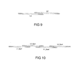
In Figur 9 ist eine bevorzugte Spulenform für Radsensoren dargestellt. Die Spulen L1 und L2 sind scheibenförmig ausgebildet und in Spiralen gewickelt. Die Höhe der Scheibenspulen entspricht dem Durchmesser des Wicklungsdrahtes und ist folglich derart gering, dass die beiden sich überlappenden Spulen L1 und L2 ohne Neigung in das Gehäuse eines Radsensors eingebaut werden können.FIG. 9 shows a preferred coil shape for wheel sensors shown. The coils L1 and L2 are disc-shaped and wrapped in spirals. The height of the disc coils corresponds to the diameter of the winding wire and is consequently so small that the two overlapping coils L1 and L2 built into the housing of a wheel sensor without inclination can be.
Figur 10 veranschaulicht einen Doppelsensor mit Scheibenspulen L1_Sys1 und L2_Sys1 sowie L1_Sys1 und L2_Sys2, wobei sich auch die benachbarten Spulen L2_Sys1 und L1_Sys2 der beiden Sensorsysteme Sys1 und Sys2 überlappenFigure 10 illustrates a double sensor with disc coils L1_Sys1 and L2_Sys1 as well as L1_Sys1 and L2_Sys2, where also the adjacent coils L2_Sys1 and L1_Sys2 of the two Sensor systems Sys1 and Sys2 overlap
Die Erfindung beschränkt sich nicht auf die vorstehend angegebenen Ausführungsbeispiele. Vielmehr ist eine Anzahl von Varianten denkbar, welche auch bei grundsätzlich anders gearteter Ausführung von den Merkmalen der Erfindung Gebrauch machen.The invention is not limited to those specified above Embodiments. Rather is a number of Variants conceivable, which are also fundamentally different Execution make use of the features of the invention.
Claims (10)
dadurch gekennzeichnet, dass
eine erste kernlose Spule (La) und eine innerhalb dieser angeordnete, bei gemeinsamer Beströmung ein gegensinniges Magnetfeld (BLi) erzeugende zweite kernlose Spule (Li) vorgesehen sind, wobei die Windungsebenen der Spulen (La, Li) im Wesentlichen übereinstimmen und die Windungszahlen (nLi und nLa) der Spulen (Li und La) umgekehrt proportional zu den Spulenflächen (ALa und ALi) sind.Wheel sensor, in particular for a track vacancy detection system, with at least one track-side inductive sensor for detecting a magnetic field change as a result of iron wheels of a rail vehicle traveling over the track and an arrangement having coreless coils (L1, L2; La, Li) to compensate for disturbing magnetic fields ( s , B Stör ) .
characterized in that
a first coreless coil (La) and a second coreless coil (Li) which is arranged within the coil and which generates an opposing magnetic field (B Li ) when the current flows together, the winding planes of the coils (La, Li) essentially matching and the number of turns ( n Li and n La ) of the coils (Li and La) are inversely proportional to the coil areas (A La and A Li ).
dadurch gekennzeichnet, dass
die zweite Spule (Li) zentrisch innerhalb der ersten Spule (La) angeordnet ist.Wheel sensor according to claim 1,
characterized in that
the second coil (Li) is arranged centrally within the first coil (La).
dadurch gekennzeichnet, dass
zwei kernlose Spulen (L1, L2) mit im Wesentlichen gleicher Geometrie und gleicher Windungszahlen vorgesehen sind, deren Windungsebenen zueinander im Wesentlichen parallel verlaufen, wobei sich die Spulen (L1, L2) in Vertikalprojektion überlappen und bei gemeinsamer Beströmung gegensinnige Magnetfelder erzeugen.Wheel sensor, in particular for a track vacancy detection system, with at least one track-side inductive sensor for detecting a magnetic field change as a result of iron wheels of a rail vehicle traveling over the track and an arrangement having coreless coils (L1, L2) for compensating interfering magnetic fields ( s , B Stör ),
characterized in that
two coreless coils (L1, L2) with essentially the same geometry and the same number of turns are provided, the winding planes of which run essentially parallel to one another, the coils (L1, L2) overlapping in a vertical projection and generating opposing magnetic fields when they are supplied with current.
dadurch gekennzeichnet, dass die Spulen (L1, L2; L1Sys1, L2Sys1, L1_Sys2, L2_Sys2) als Scheibenspulen, deren Höhe dem Durchmesser des verwendeten Leiters entspricht, ausgebildet sind.Wheel sensor according to one of the preceding claims,
characterized in that the coils (L1, L2; L1Sys1, L2Sys1, L1_Sys2, L2_Sys2) are designed as disc coils, the height of which corresponds to the diameter of the conductor used.
dadurch gekennzeichnet, dass
die Windungsebenen der Spulen (L1, L2; La, Li) im Wesentlichen parallel zur Gleisebene verlaufen.Wheel sensor according to one of the preceding claims,
characterized in that
the winding levels of the coils (L1, L2; La, Li) run essentially parallel to the track level.
dadurch gekennzeichnet, dass
die Windungsebenen der Spulen (L1_1, L2_1; L2_2, L2_1) zur Gleisebene eine im Wesentlichen in Gleislängsrichtung orientierte Neigung aufweisen und die Verbindungslinie der Spulenmittelpunkte auf einer horizontalen Ebene gleisparallel verläuft.Wheel sensor according to claim 3,
characterized in that
the winding planes of the coils (L1_1, L2_1; L2_2, L2_1) to the track plane have an inclination oriented essentially in the longitudinal direction of the track and the connecting line of the coil center points runs parallel to the track on a horizontal plane.
dadurch gekennzeichnet, dass
die Spulen (L1, L2; Li, La) runde, insbesondere kreisförmige und/oder ovale Windungen aufweisen.Wheel sensor according to one of the preceding claims,
characterized in that
the coils (L1, L2; Li, La) have round, in particular circular and / or oval windings.
die paarweise Verwendung von in Gleisrichtung beabstandeten Radsensoren nach einem der vorangehenden Ansprüche. Wheel sensor arrangement dependent on the direction of travel, characterized by
the paired use of spaced wheel sensors according to one of the preceding claims.
die Verwendung von Radsensoren nach Anspruch 5, wobei die Windungsebenen der Spulenpaare (L1_1 und L2_1; L2_2 und L1_2) dachförmig in entgegengesetzte Richtungen orientierte Neigungen aufweisen.Direction-dependent wheel sensor arrangement according to claim 8, characterized by
the use of wheel sensors according to claim 5, wherein the winding planes of the coil pairs (L1_1 and L2_1; L2_2 and L1_2) have inclinations oriented in a roof shape in opposite directions.
die paarweise Verwendung von in Gleisrichtung sich überlappenden Radsensoren nach einem der vorangehenden Ansprüche.Wheel sensor arrangement dependent on the direction of travel, characterized by
the paired use of overlapping in the track direction wheel sensors according to one of the preceding claims.
Applications Claiming Priority (2)
| Application Number | Priority Date | Filing Date | Title |
|---|---|---|---|
| DE10137519A DE10137519A1 (en) | 2001-07-30 | 2001-07-30 | Wheel sensor for a unit signaling a clear railway line has an inductive sensor on a railway line to detect a change in a magnetic field as the iron wheels of a railway vehicle pass over a rail |
| DE10137519 | 2001-07-30 |
Publications (2)
| Publication Number | Publication Date |
|---|---|
| EP1288098A1 true EP1288098A1 (en) | 2003-03-05 |
| EP1288098B1 EP1288098B1 (en) | 2008-12-31 |
Family
ID=7693880
Family Applications (1)
| Application Number | Title | Priority Date | Filing Date |
|---|---|---|---|
| EP02090264A Expired - Lifetime EP1288098B1 (en) | 2001-07-30 | 2002-07-17 | Wheel sensor and arrangement |
Country Status (6)
| Country | Link |
|---|---|
| EP (1) | EP1288098B1 (en) |
| AT (1) | ATE419158T1 (en) |
| DE (2) | DE10137519A1 (en) |
| DK (1) | DK1288098T3 (en) |
| ES (1) | ES2316521T3 (en) |
| PT (1) | PT1288098E (en) |
Cited By (3)
| Publication number | Priority date | Publication date | Assignee | Title |
|---|---|---|---|---|
| DE102009007068A1 (en) | 2009-01-29 | 2010-08-12 | Siemens Aktiengesellschaft | wheel sensor |
| EP2305533A3 (en) * | 2004-07-16 | 2012-04-18 | Lynxrail Corporation | Apparatus for detecting hunting and angle of attack of a rail vehicle wheelset |
| EP3569466A1 (en) * | 2018-05-14 | 2019-11-20 | Pintsch GmbH | Sensor for detecting metal parts and method for reducing a magnetic field |
Families Citing this family (9)
| Publication number | Priority date | Publication date | Assignee | Title |
|---|---|---|---|---|
| DE102005023726B4 (en) * | 2005-05-23 | 2007-11-22 | Frauscher Gmbh | Method and device for avoiding unwanted influences of double sensors |
| DE102007023476B4 (en) | 2007-05-15 | 2009-07-09 | Siemens Ag | wheel sensor |
| DE102007023475B4 (en) | 2007-05-15 | 2009-07-09 | Siemens Ag | wheel sensor |
| DE102008056481A1 (en) | 2008-11-05 | 2010-05-06 | Siemens Aktiengesellschaft | wheel sensor |
| DE102009053257B4 (en) * | 2009-11-05 | 2013-10-02 | Siemens Aktiengesellschaft | wheel sensor |
| DE102012212939A1 (en) | 2012-07-24 | 2014-01-30 | Siemens Aktiengesellschaft | Wheel sensor, particularly for train detection system, has inductive sensor for detecting magnetic field change as result of iron wheels of rail vehicle, where inductive sensor is arranged at side of rail of track |
| DE102017220281A1 (en) | 2017-11-14 | 2019-05-16 | Siemens Aktiengesellschaft | sensor device |
| DE102018111448A1 (en) * | 2018-05-14 | 2019-11-14 | PINTSCH TIEFENBACH GmbH | Sensor for detecting metal parts, and method for attenuating a magnetic field |
| DE102021212809A1 (en) | 2021-11-15 | 2023-05-17 | Siemens Mobility GmbH | Sensor device and method for detecting a change in magnetic field |
Citations (4)
| Publication number | Priority date | Publication date | Assignee | Title |
|---|---|---|---|---|
| US3882374A (en) * | 1974-04-18 | 1975-05-06 | Us Army | Transmitting-receiving coil configuration |
| DD261004A1 (en) * | 1987-06-25 | 1988-10-12 | Deutsche Reichsbahn | MAGNETOSTATIC PULSE ENGINE |
| DE19709844A1 (en) * | 1997-02-28 | 1998-09-03 | Siemens Ag | Sensor esp. wheel sensor for rail vehicle |
| DE19915597A1 (en) * | 1998-04-08 | 1999-12-30 | Josef Frauscher | Wheel sensor for railway monitoring installations |
Family Cites Families (1)
| Publication number | Priority date | Publication date | Assignee | Title |
|---|---|---|---|---|
| DE3842882A1 (en) * | 1988-12-20 | 1990-06-21 | Knorr Bremse Ag | METHOD AND ARRANGEMENT FOR SUPPRESSING THE INTERFERENCE OF MAGNETIC BRAKES ON MAGNETIC AXLE COUNTERS |
-
2001
- 2001-07-30 DE DE10137519A patent/DE10137519A1/en not_active Ceased
-
2002
- 2002-07-17 EP EP02090264A patent/EP1288098B1/en not_active Expired - Lifetime
- 2002-07-17 ES ES02090264T patent/ES2316521T3/en not_active Expired - Lifetime
- 2002-07-17 AT AT02090264T patent/ATE419158T1/en active
- 2002-07-17 DE DE50213159T patent/DE50213159D1/en not_active Expired - Lifetime
- 2002-07-17 PT PT02090264T patent/PT1288098E/en unknown
- 2002-07-17 DK DK02090264T patent/DK1288098T3/en active
Patent Citations (4)
| Publication number | Priority date | Publication date | Assignee | Title |
|---|---|---|---|---|
| US3882374A (en) * | 1974-04-18 | 1975-05-06 | Us Army | Transmitting-receiving coil configuration |
| DD261004A1 (en) * | 1987-06-25 | 1988-10-12 | Deutsche Reichsbahn | MAGNETOSTATIC PULSE ENGINE |
| DE19709844A1 (en) * | 1997-02-28 | 1998-09-03 | Siemens Ag | Sensor esp. wheel sensor for rail vehicle |
| DE19915597A1 (en) * | 1998-04-08 | 1999-12-30 | Josef Frauscher | Wheel sensor for railway monitoring installations |
Cited By (3)
| Publication number | Priority date | Publication date | Assignee | Title |
|---|---|---|---|---|
| EP2305533A3 (en) * | 2004-07-16 | 2012-04-18 | Lynxrail Corporation | Apparatus for detecting hunting and angle of attack of a rail vehicle wheelset |
| DE102009007068A1 (en) | 2009-01-29 | 2010-08-12 | Siemens Aktiengesellschaft | wheel sensor |
| EP3569466A1 (en) * | 2018-05-14 | 2019-11-20 | Pintsch GmbH | Sensor for detecting metal parts and method for reducing a magnetic field |
Also Published As
| Publication number | Publication date |
|---|---|
| DE50213159D1 (en) | 2009-02-12 |
| ES2316521T3 (en) | 2009-04-16 |
| PT1288098E (en) | 2009-02-02 |
| DK1288098T3 (en) | 2009-04-20 |
| DE10137519A1 (en) | 2003-02-13 |
| EP1288098B1 (en) | 2008-12-31 |
| ATE419158T1 (en) | 2009-01-15 |
Similar Documents
| Publication | Publication Date | Title |
|---|---|---|
| EP0900997B1 (en) | Inductive Angle Sensor | |
| EP0901002B1 (en) | Inductive angle sensor for a motor vehicle | |
| EP1288098B1 (en) | Wheel sensor and arrangement | |
| DE60130700T2 (en) | Inductive position sensor | |
| EP2349810B1 (en) | Wheel sensor | |
| EP3107791B1 (en) | Sensor device for detecting a change in a magnetic field and track-bound transportation system having at least one such sensor device | |
| EP2591316A1 (en) | Inductive sensor device and inductive proximity sensor with an inductive sensor device | |
| AT406139B (en) | WHEEL SENSOR | |
| EP0340660B1 (en) | Device at railways to produce presence criteria of rail-bound wheels | |
| DE10221577B3 (en) | Magnetic wheel sensor | |
| DE19641392B4 (en) | sensor | |
| DE2335280C2 (en) | Vehicle operated device | |
| DE2937650C2 (en) | Eddy current probe for scanning the surface of a metallic test part | |
| DE102007023476B4 (en) | wheel sensor | |
| EP2382120B1 (en) | Wheel sensor | |
| DE2201769C3 (en) | Vehicle-operated track contact to generate presence and / or direction criteria | |
| DE3107604C2 (en) | Arrangement for rail contacts that can be influenced inductively | |
| EP2211149B1 (en) | Route/position measurement device | |
| EP0495267B1 (en) | Apparatus for checking coins or similar metal discs | |
| EP3294608B1 (en) | Sensor device for detecting a wheel moving along a rail | |
| DE3916730A1 (en) | Arrangement for the track guidance of a vehicle over passive guiding means | |
| DE2127451B2 (en) | Vehicle receiver circuit for traffic warning signals - uses broadband and narrow-band resonant circuits coupled together via phase shifter | |
| AT501703A1 (en) | INDUCTIVE PULL CONTROL SYSTEM | |
| EP3569466A1 (en) | Sensor for detecting metal parts and method for reducing a magnetic field | |
| DE3720576A1 (en) | Device on an electronic double rail contact |
Legal Events
| Date | Code | Title | Description |
|---|---|---|---|
| PUAI | Public reference made under article 153(3) epc to a published international application that has entered the european phase |
Free format text: ORIGINAL CODE: 0009012 |
|
| AK | Designated contracting states |
Kind code of ref document: A1 Designated state(s): AT BE BG CH CY CZ DE DK EE ES FI FR GB GR IE IT LI LU MC NL PT SE SK TR |
|
| AX | Request for extension of the european patent |
Extension state: AL LT LV MK RO SI |
|
| 17P | Request for examination filed |
Effective date: 20030317 |
|
| AKX | Designation fees paid |
Designated state(s): AT BE BG CH CY CZ DE DK EE ES FI FR GB GR IE IT LI LU MC NL PT SE SK TR |
|
| REG | Reference to a national code |
Ref country code: SE Ref legal event code: TRGR |
|
| RTI1 | Title (correction) |
Free format text: WHEEL SENSOR AND ARRANGEMENT |
|
| GRAP | Despatch of communication of intention to grant a patent |
Free format text: ORIGINAL CODE: EPIDOSNIGR1 |
|
| GRAS | Grant fee paid |
Free format text: ORIGINAL CODE: EPIDOSNIGR3 |
|
| GRAA | (expected) grant |
Free format text: ORIGINAL CODE: 0009210 |
|
| AK | Designated contracting states |
Kind code of ref document: B1 Designated state(s): AT BE BG CH CY CZ DE DK EE ES FI FR GB GR IE IT LI LU MC NL PT SE SK TR |
|
| REG | Reference to a national code |
Ref country code: CH Ref legal event code: EP Ref country code: GB Ref legal event code: FG4D Free format text: NOT ENGLISH |
|
| REG | Reference to a national code |
Ref country code: CH Ref legal event code: NV Representative=s name: SIEMENS SCHWEIZ AG |
|
| REG | Reference to a national code |
Ref country code: PT Ref legal event code: SC4A Free format text: AVAILABILITY OF NATIONAL TRANSLATION Effective date: 20090120 |
|
| REF | Corresponds to: |
Ref document number: 50213159 Country of ref document: DE Date of ref document: 20090212 Kind code of ref document: P |
|
| REG | Reference to a national code |
Ref country code: IE Ref legal event code: FG4D Free format text: LANGUAGE OF EP DOCUMENT: GERMAN |
|
| REG | Reference to a national code |
Ref country code: GR Ref legal event code: EP Ref document number: 20090400630 Country of ref document: GR |
|
| REG | Reference to a national code |
Ref country code: ES Ref legal event code: FG2A Ref document number: 2316521 Country of ref document: ES Kind code of ref document: T3 |
|
| REG | Reference to a national code |
Ref country code: DK Ref legal event code: T3 |
|
| PG25 | Lapsed in a contracting state [announced via postgrant information from national office to epo] |
Ref country code: EE Free format text: LAPSE BECAUSE OF FAILURE TO SUBMIT A TRANSLATION OF THE DESCRIPTION OR TO PAY THE FEE WITHIN THE PRESCRIBED TIME-LIMIT Effective date: 20081231 |
|
| PG25 | Lapsed in a contracting state [announced via postgrant information from national office to epo] |
Ref country code: CZ Free format text: LAPSE BECAUSE OF FAILURE TO SUBMIT A TRANSLATION OF THE DESCRIPTION OR TO PAY THE FEE WITHIN THE PRESCRIBED TIME-LIMIT Effective date: 20081231 |
|
| PG25 | Lapsed in a contracting state [announced via postgrant information from national office to epo] |
Ref country code: SK Free format text: LAPSE BECAUSE OF FAILURE TO SUBMIT A TRANSLATION OF THE DESCRIPTION OR TO PAY THE FEE WITHIN THE PRESCRIBED TIME-LIMIT Effective date: 20081231 |
|
| PLBE | No opposition filed within time limit |
Free format text: ORIGINAL CODE: 0009261 |
|
| STAA | Information on the status of an ep patent application or granted ep patent |
Free format text: STATUS: NO OPPOSITION FILED WITHIN TIME LIMIT |
|
| PGFP | Annual fee paid to national office [announced via postgrant information from national office to epo] |
Ref country code: FI Payment date: 20090709 Year of fee payment: 8 |
|
| 26N | No opposition filed |
Effective date: 20091001 |
|
| PG25 | Lapsed in a contracting state [announced via postgrant information from national office to epo] |
Ref country code: BG Free format text: LAPSE BECAUSE OF FAILURE TO SUBMIT A TRANSLATION OF THE DESCRIPTION OR TO PAY THE FEE WITHIN THE PRESCRIBED TIME-LIMIT Effective date: 20090331 |
|
| PG25 | Lapsed in a contracting state [announced via postgrant information from national office to epo] |
Ref country code: MC Free format text: LAPSE BECAUSE OF NON-PAYMENT OF DUE FEES Effective date: 20090731 |
|
| PGFP | Annual fee paid to national office [announced via postgrant information from national office to epo] |
Ref country code: BE Payment date: 20090731 Year of fee payment: 8 |
|
| REG | Reference to a national code |
Ref country code: FR Ref legal event code: ST Effective date: 20100331 |
|
| PG25 | Lapsed in a contracting state [announced via postgrant information from national office to epo] |
Ref country code: FR Free format text: LAPSE BECAUSE OF NON-PAYMENT OF DUE FEES Effective date: 20090731 |
|
| PGFP | Annual fee paid to national office [announced via postgrant information from national office to epo] |
Ref country code: GR Payment date: 20090713 Year of fee payment: 8 |
|
| BERE | Be: lapsed |
Owner name: SIEMENS A.G. Effective date: 20100731 |
|
| PG25 | Lapsed in a contracting state [announced via postgrant information from national office to epo] |
Ref country code: LU Free format text: LAPSE BECAUSE OF NON-PAYMENT OF DUE FEES Effective date: 20090717 |
|
| PG25 | Lapsed in a contracting state [announced via postgrant information from national office to epo] |
Ref country code: FI Free format text: LAPSE BECAUSE OF NON-PAYMENT OF DUE FEES Effective date: 20100717 |
|
| PG25 | Lapsed in a contracting state [announced via postgrant information from national office to epo] |
Ref country code: GR Free format text: LAPSE BECAUSE OF NON-PAYMENT OF DUE FEES Effective date: 20110202 Ref country code: BE Free format text: LAPSE BECAUSE OF NON-PAYMENT OF DUE FEES Effective date: 20100731 |
|
| PG25 | Lapsed in a contracting state [announced via postgrant information from national office to epo] |
Ref country code: TR Free format text: LAPSE BECAUSE OF FAILURE TO SUBMIT A TRANSLATION OF THE DESCRIPTION OR TO PAY THE FEE WITHIN THE PRESCRIBED TIME-LIMIT Effective date: 20081231 |
|
| PG25 | Lapsed in a contracting state [announced via postgrant information from national office to epo] |
Ref country code: CY Free format text: LAPSE BECAUSE OF FAILURE TO SUBMIT A TRANSLATION OF THE DESCRIPTION OR TO PAY THE FEE WITHIN THE PRESCRIBED TIME-LIMIT Effective date: 20081231 |
|
| PGFP | Annual fee paid to national office [announced via postgrant information from national office to epo] |
Ref country code: IE Payment date: 20140723 Year of fee payment: 13 |
|
| PGFP | Annual fee paid to national office [announced via postgrant information from national office to epo] |
Ref country code: PT Payment date: 20140120 Year of fee payment: 13 |
|
| PGFP | Annual fee paid to national office [announced via postgrant information from national office to epo] |
Ref country code: NL Payment date: 20150703 Year of fee payment: 14 |
|
| PGFP | Annual fee paid to national office [announced via postgrant information from national office to epo] |
Ref country code: DE Payment date: 20150918 Year of fee payment: 14 Ref country code: ES Payment date: 20150807 Year of fee payment: 14 Ref country code: GB Payment date: 20150709 Year of fee payment: 14 Ref country code: DK Payment date: 20150721 Year of fee payment: 14 |
|
| PGFP | Annual fee paid to national office [announced via postgrant information from national office to epo] |
Ref country code: AT Payment date: 20150604 Year of fee payment: 14 Ref country code: SE Payment date: 20150706 Year of fee payment: 14 |
|
| PGFP | Annual fee paid to national office [announced via postgrant information from national office to epo] |
Ref country code: IT Payment date: 20150727 Year of fee payment: 14 |
|
| REG | Reference to a national code |
Ref country code: PT Ref legal event code: MM4A Free format text: LAPSE DUE TO NON-PAYMENT OF FEES Effective date: 20160118 |
|
| PGFP | Annual fee paid to national office [announced via postgrant information from national office to epo] |
Ref country code: CH Payment date: 20151002 Year of fee payment: 14 |
|
| REG | Reference to a national code |
Ref country code: GR Ref legal event code: ML Ref document number: 20090400630 Country of ref document: GR Effective date: 20110202 |
|
| REG | Reference to a national code |
Ref country code: IE Ref legal event code: MM4A |
|
| PG25 | Lapsed in a contracting state [announced via postgrant information from national office to epo] |
Ref country code: PT Free format text: LAPSE BECAUSE OF NON-PAYMENT OF DUE FEES Effective date: 20160118 |
|
| PG25 | Lapsed in a contracting state [announced via postgrant information from national office to epo] |
Ref country code: IE Free format text: LAPSE BECAUSE OF NON-PAYMENT OF DUE FEES Effective date: 20150717 |
|
| REG | Reference to a national code |
Ref country code: DE Ref legal event code: R119 Ref document number: 50213159 Country of ref document: DE |
|
| REG | Reference to a national code |
Ref country code: DK Ref legal event code: EBP Effective date: 20170131 |
|
| REG | Reference to a national code |
Ref country code: CH Ref legal event code: PL |
|
| REG | Reference to a national code |
Ref country code: NL Ref legal event code: MM Effective date: 20160801 |
|
| REG | Reference to a national code |
Ref country code: SE Ref legal event code: EUG |
|
| REG | Reference to a national code |
Ref country code: AT Ref legal event code: MM01 Ref document number: 419158 Country of ref document: AT Kind code of ref document: T Effective date: 20160717 |
|
| GBPC | Gb: european patent ceased through non-payment of renewal fee |
Effective date: 20160717 |
|
| PG25 | Lapsed in a contracting state [announced via postgrant information from national office to epo] |
Ref country code: LI Free format text: LAPSE BECAUSE OF NON-PAYMENT OF DUE FEES Effective date: 20160731 Ref country code: DE Free format text: LAPSE BECAUSE OF NON-PAYMENT OF DUE FEES Effective date: 20170201 Ref country code: SE Free format text: LAPSE BECAUSE OF NON-PAYMENT OF DUE FEES Effective date: 20160718 Ref country code: CH Free format text: LAPSE BECAUSE OF NON-PAYMENT OF DUE FEES Effective date: 20160731 Ref country code: NL Free format text: LAPSE BECAUSE OF NON-PAYMENT OF DUE FEES Effective date: 20160801 |
|
| PG25 | Lapsed in a contracting state [announced via postgrant information from national office to epo] |
Ref country code: AT Free format text: LAPSE BECAUSE OF NON-PAYMENT OF DUE FEES Effective date: 20160717 Ref country code: GB Free format text: LAPSE BECAUSE OF NON-PAYMENT OF DUE FEES Effective date: 20160717 |
|
| PG25 | Lapsed in a contracting state [announced via postgrant information from national office to epo] |
Ref country code: IT Free format text: LAPSE BECAUSE OF NON-PAYMENT OF DUE FEES Effective date: 20160717 |
|
| PG25 | Lapsed in a contracting state [announced via postgrant information from national office to epo] |
Ref country code: DK Free format text: LAPSE BECAUSE OF NON-PAYMENT OF DUE FEES Effective date: 20160731 |
|
| PG25 | Lapsed in a contracting state [announced via postgrant information from national office to epo] |
Ref country code: ES Free format text: LAPSE BECAUSE OF NON-PAYMENT OF DUE FEES Effective date: 20160718 |
|
| REG | Reference to a national code |
Ref country code: ES Ref legal event code: FD2A Effective date: 20181128 |