EP1291745A2 - Programmable controller with RF wireless interface - Google Patents
Programmable controller with RF wireless interface Download PDFInfo
- Publication number
- EP1291745A2 EP1291745A2 EP02078479A EP02078479A EP1291745A2 EP 1291745 A2 EP1291745 A2 EP 1291745A2 EP 02078479 A EP02078479 A EP 02078479A EP 02078479 A EP02078479 A EP 02078479A EP 1291745 A2 EP1291745 A2 EP 1291745A2
- Authority
- EP
- European Patent Office
- Prior art keywords
- programmable logic
- chip set
- logic controller
- controller
- radio frequency
- Prior art date
- Legal status (The legal status is an assumption and is not a legal conclusion. Google has not performed a legal analysis and makes no representation as to the accuracy of the status listed.)
- Granted
Links
Images

Classifications
-
- H—ELECTRICITY
- H05—ELECTRIC TECHNIQUES NOT OTHERWISE PROVIDED FOR
- H05K—PRINTED CIRCUITS; CASINGS OR CONSTRUCTIONAL DETAILS OF ELECTRIC APPARATUS; MANUFACTURE OF ASSEMBLAGES OF ELECTRICAL COMPONENTS
- H05K1/00—Printed circuits
- H05K1/02—Details
- H05K1/0266—Marks, test patterns or identification means
-
- G—PHYSICS
- G05—CONTROLLING; REGULATING
- G05B—CONTROL OR REGULATING SYSTEMS IN GENERAL; FUNCTIONAL ELEMENTS OF SUCH SYSTEMS; MONITORING OR TESTING ARRANGEMENTS FOR SUCH SYSTEMS OR ELEMENTS
- G05B19/00—Programme-control systems
- G05B19/02—Programme-control systems electric
- G05B19/04—Programme control other than numerical control, i.e. in sequence controllers or logic controllers
- G05B19/05—Programmable logic controllers, e.g. simulating logic interconnections of signals according to ladder diagrams or function charts
- G05B19/054—Input/output
-
- G—PHYSICS
- G05—CONTROLLING; REGULATING
- G05B—CONTROL OR REGULATING SYSTEMS IN GENERAL; FUNCTIONAL ELEMENTS OF SUCH SYSTEMS; MONITORING OR TESTING ARRANGEMENTS FOR SUCH SYSTEMS OR ELEMENTS
- G05B2219/00—Program-control systems
- G05B2219/10—Plc systems
- G05B2219/15—Plc structure of the system
- G05B2219/15038—Internet, tcp-ip, web server see under S05B219-40
-
- G—PHYSICS
- G05—CONTROLLING; REGULATING
- G05B—CONTROL OR REGULATING SYSTEMS IN GENERAL; FUNCTIONAL ELEMENTS OF SUCH SYSTEMS; MONITORING OR TESTING ARRANGEMENTS FOR SUCH SYSTEMS OR ELEMENTS
- G05B2219/00—Program-control systems
- G05B2219/10—Plc systems
- G05B2219/15—Plc structure of the system
- G05B2219/15117—Radio link, wireless
-
- G—PHYSICS
- G05—CONTROLLING; REGULATING
- G05B—CONTROL OR REGULATING SYSTEMS IN GENERAL; FUNCTIONAL ELEMENTS OF SUCH SYSTEMS; MONITORING OR TESTING ARRANGEMENTS FOR SUCH SYSTEMS OR ELEMENTS
- G05B2219/00—Program-control systems
- G05B2219/30—Nc systems
- G05B2219/31—From computer integrated manufacturing till monitoring
- G05B2219/31156—Network structure, internet
-
- G—PHYSICS
- G05—CONTROLLING; REGULATING
- G05B—CONTROL OR REGULATING SYSTEMS IN GENERAL; FUNCTIONAL ELEMENTS OF SUCH SYSTEMS; MONITORING OR TESTING ARRANGEMENTS FOR SUCH SYSTEMS OR ELEMENTS
- G05B2219/00—Program-control systems
- G05B2219/30—Nc systems
- G05B2219/31—From computer integrated manufacturing till monitoring
- G05B2219/31186—TCP-IP internet protocol
-
- G—PHYSICS
- G05—CONTROLLING; REGULATING
- G05B—CONTROL OR REGULATING SYSTEMS IN GENERAL; FUNCTIONAL ELEMENTS OF SUCH SYSTEMS; MONITORING OR TESTING ARRANGEMENTS FOR SUCH SYSTEMS OR ELEMENTS
- G05B2219/00—Program-control systems
- G05B2219/30—Nc systems
- G05B2219/31—From computer integrated manufacturing till monitoring
- G05B2219/31205—Remote transmission of measured values from site, local to host
-
- H—ELECTRICITY
- H05—ELECTRIC TECHNIQUES NOT OTHERWISE PROVIDED FOR
- H05K—PRINTED CIRCUITS; CASINGS OR CONSTRUCTIONAL DETAILS OF ELECTRIC APPARATUS; MANUFACTURE OF ASSEMBLAGES OF ELECTRICAL COMPONENTS
- H05K2201/00—Indexing scheme relating to printed circuits covered by H05K1/00
- H05K2201/10—Details of components or other objects attached to or integrated in a printed circuit board
- H05K2201/10007—Types of components
- H05K2201/10098—Components for radio transmission, e.g. radio frequency identification [RFID] tag, printed or non-printed antennas
-
- Y—GENERAL TAGGING OF NEW TECHNOLOGICAL DEVELOPMENTS; GENERAL TAGGING OF CROSS-SECTIONAL TECHNOLOGIES SPANNING OVER SEVERAL SECTIONS OF THE IPC; TECHNICAL SUBJECTS COVERED BY FORMER USPC CROSS-REFERENCE ART COLLECTIONS [XRACs] AND DIGESTS
- Y02—TECHNOLOGIES OR APPLICATIONS FOR MITIGATION OR ADAPTATION AGAINST CLIMATE CHANGE
- Y02P—CLIMATE CHANGE MITIGATION TECHNOLOGIES IN THE PRODUCTION OR PROCESSING OF GOODS
- Y02P90/00—Enabling technologies with a potential contribution to greenhouse gas [GHG] emissions mitigation
- Y02P90/02—Total factory control, e.g. smart factories, flexible manufacturing systems [FMS] or integrated manufacturing systems [IMS]
Definitions
- the present invention generally concerns communication modules for programmable controllers that are used to control industrial assembly applications.
- the invention concerns an interface module employing radio frequency identification (RFID) technology to facilitate wireless communication between the programmable controller and other devices both within the controller and external to the controller.
- RFID radio frequency identification
- PLCs programmable logic controllers
- communication between a PLC and other devices, such as external devices is typically accomplished by electro-mechanical means through a backplane or fixed connector on the PLC.
- PLCs have traditionally been programmed by transmission of information through a cable that is attached to a program port on the body of the PLC. Such attachment can be cumbersome, unreliable, and relatively costly.
- the prior art has in some instances used modems to control, monitor and test/debug PLCs from remote locations.
- the modem devices are also typically connected to a PLC through the backplane or a fixed connector on the PLC.
- Radio frequency identification (“RFID”) technology has been used in various fields as a means of identifying articles. RFID technology has been used for identifying parcels, luggage, and other materials.
- An RFID system generally consists of an antenna; a transmitter/receiver and; a transponder (called an RF chip set or tag) that is electronically programmed with unique identification information.
- the antenna emits radio signals that activate the RFID tag and write and read data to and from the RFID tag.
- an antenna mounted on a toll booth may monitor various aspects of traffic by sending RF signals to an RF tag mounted within each passing automobile.
- RFID tags are available in many different sizes/shapes and are generally characterized as either passive or active. Active tags are internally powered and are typically readable and writable. Active tags have relatively large amounts of memory. Passive tags operate without an internal power source. Passive tags obtain operating power generated from the reader. Passive tags are typically read-only. RFID systems provide for wireless communication through many materials. RFID tags can also be read at high speeds.
- RFID technology is implemented through an integrated chip set with a PROM for programming an identification (ID) code.
- the RFID chip set is placed on an article and the ID code may be transmitted to, and stored in, the RFID chip.
- the ID code is then scanned by a transmitter/receiver.
- the RFID chip is passive and employs the power of the transmitting signal to energize the RFID coil and to return a signal including the ID code or a signal affirming the ID code.
- the invention provides a programmable logic controller having a wireless communication interface.
- the controller generally includes a housing containing one or more circuit boards.
- the housing typically stores an input module, a central processing unit, and an output module.
- the controller also includes an interface means for providing wireless communication with said programmable logic controller via radio frequency transmissions.
- the interface means is mounted to and contacts the active elements of an integrated circuit on one or more of the circuit boards in the controller.
- a radio frequency identification chip set (or tag) is mounted to and contacts one or more circuit boards in the central processing unit of the controller.
- the chip set provides for radio frequency communication between the controller and other components within or external to the PLC.
- the chip set may be mounted to the circuit board by a standard surface mount, by a through-hole mounting device, or by a chip-on-board mounting device. Any mounting device must connect the chip set to the active elements of the integrated circuit on the circuit board. In one preferred embodiment, the chip set may actually be incorporated into part of the schematic of the integrated circuit.
- the antenna of the radio frequency chip set is attached to the circuit board by adhesive means or more preferably by etching the antenna directly to the board.
- two or more circuit boards within the controller include the chip set, and the boards are capable of radio frequency communication with one another.
- the communication interface is provided for transferring programming instructions to the central processing unit by radio frequency communication.
- the radio frequency communication of the wireless interface may cause interference with the operation of the controller.
- the chip set may be shielded, or may be configured to operate in a frequency range outside of the frequencies at which the controller operates.
- the invention also provides a method for wireless communication with a PLC.
- the method is implemented by mounting the RFID chip set to at least one circuit board within the housing of the PLC and providing an antenna at a remote location to enable wireless communication of information between the chip set and the antenna.
- the method of the invention enables the wireless communication of programming instructions to the controller or of error notification signals from the controller to a remote location.
- Fig. 1 shows the PLC of the invention incorporating the wireless communications interface.
- the PLC includes a housing 2 that contains an input module 4, a central processing unit 7 and an output module 9.
- the PLC includes one or more circuit boards 11 (See Fig. 2).
- a network interface 12 may be provided for connecting the PLC to a network, such as an on-line network as a Local Area Network or the Internet. Information received or stored on the chip, therefore, may be communicated over the network.
- a network such as an on-line network as a Local Area Network or the Internet.
- Information received or stored on the chip therefore, may be communicated over the network.
- network communications particularly TCP/IP, will understand readily how such communications are to be implemented.
- the wireless interface 15 is to be mounted on a circuit board 11 contained within the housing 2 of the PLC.
- the wireless interface employs a standard RFID chip set, such as Texas Instruments Tag it®.
- the RFID is a passive receiver/transmitter.
- the RFID chip set 15 is mounted to an integrated circuit on the circuit board 11 of the programmable controller. This will allow separate integrated circuits to be in communication via wireless connection.
- the RFID chip set 15 may contact the active elements of the integrated circuit by standard surface mount, a through hole mount, or a chip-on-board mount.
- the RFID chip set 15 may also be a part of the schematic of the integrated circuit.
- integrated circuits equipped with the wireless interface on a board can facilitate communication between the PLC and other devices, such as any of the components in the computer.
- the circuit board may communicate wirelessly using radio frequency with other circuit boards similarly equipped with the RFID chip set, without requiring communication through connectors 19.
- a PLC equipped with the RFID chip set may communicate wirelessly with remotely-located modules such as a card and rack system 22; a programming device, such as a hand held programmer 27; or a computer 31.
- the concept may also be extended to process automation in general and may be further applicable to other industrial applications.
- the invention may be applicable to automotive diagnostics. In this case, the invention may communicate with different areas of a car or may communicate between different devices in an automobile.
- the invention may be employed to perform wireless testing from an operator's terminal 35 during the manufacturing process or to communicate wireless error code messages to a remote computer 31 during operation. This enables quick troubleshooting. In a PLC with numerous modules, the technician is able to locate the problematic module quickly, particularly in a large system where a proliferation of modules may make troubleshooting difficult.
- PLC such as the S7-200 or S7-300, Siemens Energy & Automation, Johnson City, TN
- S7-200 or S7-300 Siemens Energy & Automation, Johnson City, TN
- PLCs may be programmed via the wireless interface of the invention.
- any possibility of interference with the operation of the PLC caused by the radio frequency nature of the communication by the RFID chip set 15 may be alleviated through suitable shielding.
- Another way to address this problem is to limit the frequency range of the RFID chip set outside of the normal PLC operating frequencies.
- Another approach limits the proximity to one another of the RFID's 15 on the modules.
- the use of the wireless interface may also create problems in compliance with FCC and CE (EU) regulations. This problem may be overcome by limiting the range of the interface. Limiting the range may be accomplished by use of shielding or reducing the power output.
- the invention may be connected to a micro-chip or circuitry.
- the RFID chip set 15 may be etched into the circuit board rather than a stick on label as is the current situation.
- the RFID chip set 15 is relatively inexpensive and may alleviate connection defects that commonly occur with plug-type connectors in the backplane of the PLC. The RFID should provide a more reliable connection.
Landscapes
- Engineering & Computer Science (AREA)
- Microelectronics & Electronic Packaging (AREA)
- Physics & Mathematics (AREA)
- General Physics & Mathematics (AREA)
- Automation & Control Theory (AREA)
- Programmable Controllers (AREA)
- Transceivers (AREA)
- Selective Calling Equipment (AREA)
Abstract
Description
- The present invention generally concerns communication modules for programmable controllers that are used to control industrial assembly applications. In particular, the invention concerns an interface module employing radio frequency identification (RFID) technology to facilitate wireless communication between the programmable controller and other devices both within the controller and external to the controller.
- In the field of programmable logic controllers (PLCs), communication between a PLC and other devices, such as external devices, is typically accomplished by electro-mechanical means through a backplane or fixed connector on the PLC. For example, PLCs have traditionally been programmed by transmission of information through a cable that is attached to a program port on the body of the PLC. Such attachment can be cumbersome, unreliable, and relatively costly.
- The prior art has in some instances used modems to control, monitor and test/debug PLCs from remote locations. The modem devices are also typically connected to a PLC through the backplane or a fixed connector on the PLC.
- Radio frequency identification ("RFID") technology has been used in various fields as a means of identifying articles. RFID technology has been used for identifying parcels, luggage, and other materials. An RFID system generally consists of an antenna; a transmitter/receiver and; a transponder (called an RF chip set or tag) that is electronically programmed with unique identification information. The antenna emits radio signals that activate the RFID tag and write and read data to and from the RFID tag. For example, an antenna mounted on a toll booth may monitor various aspects of traffic by sending RF signals to an RF tag mounted within each passing automobile.
- RFID tags are available in many different sizes/shapes and are generally characterized as either passive or active. Active tags are internally powered and are typically readable and writable. Active tags have relatively large amounts of memory. Passive tags operate without an internal power source. Passive tags obtain operating power generated from the reader. Passive tags are typically read-only. RFID systems provide for wireless communication through many materials. RFID tags can also be read at high speeds.
- In one example, RFID technology is implemented through an integrated chip set with a PROM for programming an identification (ID) code. The RFID chip set is placed on an article and the ID code may be transmitted to, and stored in, the RFID chip. The ID code is then scanned by a transmitter/receiver. The RFID chip is passive and employs the power of the transmitting signal to energize the RFID coil and to return a signal including the ID code or a signal affirming the ID code.
- The use of RFID technology has been limited essentially to identification applications and has not been implemented as a means for transferring data in machines, such as PLCs. It would also be advantageous to have the wireless RFID interface as an integral part of the PLC eliminating the need for communication through the backplane and cables.
- The invention provides a programmable logic controller having a wireless communication interface. The controller generally includes a housing containing one or more circuit boards. The housing typically stores an input module, a central processing unit, and an output module. The controller also includes an interface means for providing wireless communication with said programmable logic controller via radio frequency transmissions. The interface means is mounted to and contacts the active elements of an integrated circuit on one or more of the circuit boards in the controller. For example, a radio frequency identification chip set (or tag) is mounted to and contacts one or more circuit boards in the central processing unit of the controller. The chip set provides for radio frequency communication between the controller and other components within or external to the PLC.
- The chip set may be mounted to the circuit board by a standard surface mount, by a through-hole mounting device, or by a chip-on-board mounting device. Any mounting device must connect the chip set to the active elements of the integrated circuit on the circuit board. In one preferred embodiment, the chip set may actually be incorporated into part of the schematic of the integrated circuit. The antenna of the radio frequency chip set is attached to the circuit board by adhesive means or more preferably by etching the antenna directly to the board.
- In a particular embodiment, two or more circuit boards within the controller include the chip set, and the boards are capable of radio frequency communication with one another. In another embodiment, the communication interface is provided for transferring programming instructions to the central processing unit by radio frequency communication.
- The radio frequency communication of the wireless interface may cause interference with the operation of the controller. To counteract this possibility, the chip set may be shielded, or may be configured to operate in a frequency range outside of the frequencies at which the controller operates.
- The invention also provides a method for wireless communication with a PLC. The method is implemented by mounting the RFID chip set to at least one circuit board within the housing of the PLC and providing an antenna at a remote location to enable wireless communication of information between the chip set and the antenna. The method of the invention enables the wireless communication of programming instructions to the controller or of error notification signals from the controller to a remote location.
-
- Fig. 1 shows the general construction of a PLC that may embody the wireless communications interface in accordance with the invention.
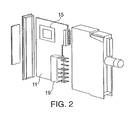
- Fig. 2 shows a circuit board of a PLC incorporating a wireless communications interface in accordance with the invention.
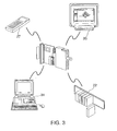
- Fig. 3 shows the circuit board of Fig. 2 in various uses employing the wireless communication feature embodied by the invention.
-
- Fig. 1 shows the PLC of the invention incorporating the wireless communications interface. The PLC includes a
housing 2 that contains aninput module 4, acentral processing unit 7 and anoutput module 9. The PLC includes one or more circuit boards 11 (See Fig. 2). - Further, a
network interface 12 may be provided for connecting the PLC to a network, such as an on-line network as a Local Area Network or the Internet. Information received or stored on the chip, therefore, may be communicated over the network. One skilled in the art of network communications, particularly TCP/IP, will understand readily how such communications are to be implemented. - As shown in Fig. 2, the
wireless interface 15 is to be mounted on acircuit board 11 contained within thehousing 2 of the PLC. The wireless interface employs a standard RFID chip set, such as Texas Instruments Tag it®. In a preferred embodiment, the RFID is a passive receiver/transmitter. According to the invention, theRFID chip set 15 is mounted to an integrated circuit on thecircuit board 11 of the programmable controller. This will allow separate integrated circuits to be in communication via wireless connection. TheRFID chip set 15 may contact the active elements of the integrated circuit by standard surface mount, a through hole mount, or a chip-on-board mount. TheRFID chip set 15 may also be a part of the schematic of the integrated circuit. - In addition, integrated circuits equipped with the wireless interface on a board can facilitate communication between the PLC and other devices, such as any of the components in the computer. Thus, the circuit board may communicate wirelessly using radio frequency with other circuit boards similarly equipped with the RFID chip set, without requiring communication through
connectors 19. - As shown in Fig. 3, with such a modified device, a PLC equipped with the RFID chip set may communicate wirelessly with remotely-located modules such as a card and
rack system 22; a programming device, such as a hand heldprogrammer 27; or acomputer 31. The concept may also be extended to process automation in general and may be further applicable to other industrial applications. For example, it is contemplated that the invention may be applicable to automotive diagnostics. In this case, the invention may communicate with different areas of a car or may communicate between different devices in an automobile. - As is also shown in Fig. 3, the invention may be employed to perform wireless testing from an operator's terminal 35 during the manufacturing process or to communicate wireless error code messages to a
remote computer 31 during operation. This enables quick troubleshooting. In a PLC with numerous modules, the technician is able to locate the problematic module quickly, particularly in a large system where a proliferation of modules may make troubleshooting difficult. - Traditionally, a PLC (such as the S7-200 or S7-300, Siemens Energy & Automation, Johnson City, TN) is programmed using a cable. The dependence upon cables is eliminated so that a programmer in the field need not worry about hardware compatibility issues. PLCs may be programmed via the wireless interface of the invention.
- Any possibility of interference with the operation of the PLC caused by the radio frequency nature of the communication by the RFID chip set 15 may be alleviated through suitable shielding. Another way to address this problem is to limit the frequency range of the RFID chip set outside of the normal PLC operating frequencies. Another approach limits the proximity to one another of the RFID's 15 on the modules.
- The use of the wireless interface may also create problems in compliance with FCC and CE (EU) regulations. This problem may be overcome by limiting the range of the interface. Limiting the range may be accomplished by use of shielding or reducing the power output.
- In addition, the invention may be connected to a micro-chip or circuitry. The RFID chip set 15 may be etched into the circuit board rather than a stick on label as is the current situation. The RFID chip set 15 is relatively inexpensive and may alleviate connection defects that commonly occur with plug-type connectors in the backplane of the PLC. The RFID should provide a more reliable connection.
- Those skilled in the art will realize that numerous modifications and variations of the present invention are possible in light of the above teachings and embodiments. Therefore, the invention should not be construed as limited to any of the foregoing embodiments, but instead should be viewed within the scope of the appended claims.
Claims (18)
- A programmable logic controller having a wireless communication interface comprising:a housing;at least one circuit board within the controller housing, the board comprising circuitry for performing controller functions; anda radio frequency identification chip set mounted to at least one of the boards and coupled to the circuitry on the at least one board, the chip set for providing radio frequency communication.
- The programmable logic controller according to claim 1, wherein the radio frequency chip set antenna is etched into the circuit board.
- The programmable logic controller according to claim 1 or 2, further comprising a chip set mount for mounting the chip set to the board.
- The programmable logic controller according to claim 3, wherein the chip set mount is selected from the group comprising a standard surface mount,
a through-hole mounting device, and
a chip-on-board mounting device. - The programmable logic controller according to claim 1, wherein the chip set comprises part of the schematic of the integrated circuit.
- The programmable logic controller according to claim 1, wherein two or more circuit boards within the controller comprise the chip set and the boards are adapted for radio frequency communication with one another.
- The programmable logic controller according to any one of claims 1-6, wherein the controller comprises a processor that receives RF signals carrying programming instructions for execution by the processor.
- The programmable logic controller according to any of claims 1-7, wherein the chip set is shielded to prevent radio frequency communication with the interface from interfering with the operation of the controller.
- The programmable logic controller according to any one of claims 1-8, wherein the chip set operates in a frequency range outside of frequencies at which the controller operates to prevent radio frequency communication with the interface from interfering with the operation of the controller.
- The programmable logic controller according to any one of claims 1-9, wherein the interface carries signals representing wireless testing instructions.
- The programmable controller according to claim 10, wherein the interface carries testing signals during manufacturing process of the controller during a manufacturing process.
- The programmable logic controller according to any one of claims 1-11, further comprising a network interface for interfacing the programmable logic controller to a network.
- The programmable logic controller according to claim 12, wherein said network interface communicates information received from said identification chip over said network.
- The programmable logic controller according to claim 13, wherein said network interface interfaces to the Internet.
- A programmable logic controller having a wireless communication interface comprising:a housing;at least one circuit board within the controller including circuitry for performing controller functions; andinterface means for providing wireless communication with said programmable logic controller, said interface means mounted to and contacting at least one of the circuit boards.
- A method for providing wireless communication with a programmable logic controller, the method comprising:providing a radio frequency identification chip set that transmits information via radio frequency signals;mounting said chip set in contacting arrangement to the active elements of an integrated circuit on at least one circuit board in the programmable logic controller; andproviding an antenna for communicating information to and from the chip set.
- The method of claim 16, wherein the information comprises programming instructions for the controller.
- The method of claim 16, wherein the information comprises error notification signals indicating when there is a problem in the controller.
Priority Applications (1)
| Application Number | Priority Date | Filing Date | Title |
|---|---|---|---|
| EP07100183.8A EP1764665B1 (en) | 2001-09-07 | 2002-08-22 | Programmable controller with RF wireless interface |
Applications Claiming Priority (2)
| Application Number | Priority Date | Filing Date | Title |
|---|---|---|---|
| US09/948,421 US6993298B2 (en) | 2001-09-07 | 2001-09-07 | Programmable controller with RF wireless interface |
| US948421 | 2001-09-07 |
Related Child Applications (1)
| Application Number | Title | Priority Date | Filing Date |
|---|---|---|---|
| EP07100183.8A Division EP1764665B1 (en) | 2001-09-07 | 2002-08-22 | Programmable controller with RF wireless interface |
Publications (3)
| Publication Number | Publication Date |
|---|---|
| EP1291745A2 true EP1291745A2 (en) | 2003-03-12 |
| EP1291745A3 EP1291745A3 (en) | 2004-03-24 |
| EP1291745B1 EP1291745B1 (en) | 2007-06-20 |
Family
ID=25487821
Family Applications (2)
| Application Number | Title | Priority Date | Filing Date |
|---|---|---|---|
| EP07100183.8A Expired - Lifetime EP1764665B1 (en) | 2001-09-07 | 2002-08-22 | Programmable controller with RF wireless interface |
| EP02078479A Expired - Lifetime EP1291745B1 (en) | 2001-09-07 | 2002-08-22 | Programmable controller with RF wireless interface |
Family Applications Before (1)
| Application Number | Title | Priority Date | Filing Date |
|---|---|---|---|
| EP07100183.8A Expired - Lifetime EP1764665B1 (en) | 2001-09-07 | 2002-08-22 | Programmable controller with RF wireless interface |
Country Status (6)
| Country | Link |
|---|---|
| US (1) | US6993298B2 (en) |
| EP (2) | EP1764665B1 (en) |
| CN (1) | CN100367138C (en) |
| AT (1) | ATE365343T1 (en) |
| DE (1) | DE60220753T2 (en) |
| ES (1) | ES2286196T3 (en) |
Cited By (9)
| Publication number | Priority date | Publication date | Assignee | Title |
|---|---|---|---|---|
| WO2004083974A1 (en) * | 2003-03-18 | 2004-09-30 | T.E.R Tecno Elettrica Ravasi S.R.L. | Integrated apparatus for use in industrial machinery |
| WO2006026870A1 (en) * | 2004-09-06 | 2006-03-16 | Tecon Ag | Method for controlling/regulating machine sequences or processes, and corresponding control/regulating unit |
| EP1785790A1 (en) * | 2005-11-11 | 2007-05-16 | Siemens Aktiengesellschaft | Programmable logic controller comprising a RFID |
| EP1840684A1 (en) * | 2006-03-27 | 2007-10-03 | Siemens Aktiengesellschaft | Automation device and system with components communicating connectionless (radio frequency) using detachable radio module FM |
| WO2007121968A2 (en) * | 2006-04-24 | 2007-11-01 | Hilscher Gesellschaft für Systemautomation mbH | Replaceable communication and control device comprising a replaceable stored-program controller and several communication interfaces |
| DE102008013075A1 (en) | 2008-03-06 | 2009-09-24 | Hilscher Gesellschaft für Systemautomation mbH | Programmable logic controller with flexible communication and control structure and method for its configuration |
| WO2010094301A1 (en) * | 2009-02-20 | 2010-08-26 | Siemens Aktiengesellschaft | Field device for process instrumentation |
| CN101273370B (en) * | 2005-07-19 | 2010-12-29 | 关卡系统股份有限公司 | RFID tags for pallets and cartons and system for attaching same |
| CN105263264A (en) * | 2015-10-08 | 2016-01-20 | 上海新跃仪表厂 | Complex wiring PCB (printed circuit board) with simple connection structure and preparation method thereof |
Families Citing this family (19)
| Publication number | Priority date | Publication date | Assignee | Title |
|---|---|---|---|---|
| US6943678B2 (en) * | 2000-01-24 | 2005-09-13 | Nextreme, L.L.C. | Thermoformed apparatus having a communications device |
| US8821285B2 (en) * | 2003-11-03 | 2014-09-02 | Intel Corporation | Gaming interface techniques for media centers |
| CN1882925B (en) * | 2003-11-17 | 2012-03-21 | 洛克威尔自动控制技术股份有限公司 | Distributed modular input/output system with wireless backplane extender |
| DE102004039677B4 (en) | 2004-05-28 | 2023-02-02 | Zumtobel Lighting Gmbh | Building management system and actuator with memory part |
| JP4324059B2 (en) * | 2004-09-03 | 2009-09-02 | 株式会社日立製作所 | IC tag mounting harness |
| DE102004050383A1 (en) * | 2004-10-15 | 2006-04-27 | Siemens Ag | Transfer of data to and from automation components |
| EP1960912A4 (en) * | 2005-11-15 | 2010-09-29 | Ils Technology Llc | Rfid with two tier connectivity, rfid in the plc rack, secure rfid tags and rfid multiplexer system |
| DE102005055426B4 (en) * | 2005-11-21 | 2011-12-29 | Xignal Technologies Ag | Circuit arrangement with a feedback, fully differential operational amplifier |
| US20080097718A1 (en) * | 2006-10-20 | 2008-04-24 | General Electric Company | Interfacing apparatus and method for mounting sensors on the same |
| US20080192812A1 (en) * | 2007-02-09 | 2008-08-14 | Marco Naeve | Wireless communication adapter for a programmable logic controller and programmable logic controller system including the same |
| WO2008145623A1 (en) * | 2007-05-29 | 2008-12-04 | Siemens Aktiengesellschaft | Control device and drive component for a machine tool, a production machine and/or a robot |
| US20090201223A1 (en) * | 2008-02-08 | 2009-08-13 | Blake Stephens | Electronic book |
| KR100986746B1 (en) | 2008-12-29 | 2010-10-08 | 재단법인 광양만권 유아이티연구소 | RFID system linked with PLC |
| KR100988035B1 (en) | 2010-03-19 | 2010-10-18 | 김민규 | Crops facilities controler having separation type plc |
| US9201416B2 (en) * | 2012-01-24 | 2015-12-01 | Fisher Controls International Llc | Asset data modules including an integral near field communication interface |
| CN104536369B (en) * | 2014-12-29 | 2017-05-10 | 张海舡 | Intelligent programmable control microwave oven and operating method thereof |
| US10963328B2 (en) * | 2018-09-05 | 2021-03-30 | Mikroelektronika D.O.O. | WiFi programmer and debugger for microcontroller and method thereof |
| CN112462664B (en) * | 2020-11-30 | 2022-03-18 | 广州仪速安电子科技有限公司 | Instrument interface data monitoring system |
| CN116774644B (en) * | 2023-08-17 | 2023-12-22 | 武汉世炬信息技术有限公司 | Industrial automation control system and method |
Citations (8)
| Publication number | Priority date | Publication date | Assignee | Title |
|---|---|---|---|---|
| US4949299A (en) * | 1987-12-04 | 1990-08-14 | Allen-Bradley Company, Inc. | Industrial control communication network and method |
| EP0926426A1 (en) * | 1997-12-23 | 1999-06-30 | Satzinger GmbH & Co. | Method of lubrication of a device with a plurality of lubrication points and central lubrication system for carrying out said method |
| EP0994350A1 (en) * | 1998-10-15 | 2000-04-19 | Radiometer Analytical S.A. | Accessory for a measuring or metering device, in particular electrochemical measurement probe |
| DE19951233A1 (en) * | 1998-11-23 | 2000-05-31 | Tripols Union Formenbau Gmbh | CNC machine with hand-held controller |
| US20010003163A1 (en) * | 1998-06-15 | 2001-06-07 | Ulrich Bungert | Automation system with radio sensor |
| DE10033335A1 (en) * | 2000-07-08 | 2002-01-17 | Battenfeld Gmbh | Electrical control system transmitting stored data to remote monitoring location from e.g. pressure injection molding machine, employs radio telephone |
| DE10032866A1 (en) * | 2000-07-06 | 2002-01-17 | Abb Research Ltd | Automisation system with software implemented control uses radio communication link between control computer and sensors and/or actuators |
| DE10032868A1 (en) * | 2000-07-06 | 2002-01-17 | Abb Research Ltd | System, especially automation system, with wireless communications between base station and sensors has base station combined with at least one actuator to form actuator/base station |
Family Cites Families (18)
| Publication number | Priority date | Publication date | Assignee | Title |
|---|---|---|---|---|
| US5214621A (en) * | 1990-12-20 | 1993-05-25 | Square D Company | Universal circuit board housing with a hinged member |
| DE4345610B4 (en) * | 1992-06-17 | 2013-01-03 | Micron Technology Inc. | Method for producing a radio-frequency identification device (HFID) |
| US6045652A (en) * | 1992-06-17 | 2000-04-04 | Micron Communications, Inc. | Method of manufacturing an enclosed transceiver |
| US5911121A (en) * | 1996-05-23 | 1999-06-08 | Ericsson Inc. | Method and apparatus for automatically configuring a control program for a mobile radio communication device |
| US5914671A (en) * | 1997-02-27 | 1999-06-22 | Micron Communications, Inc. | System and method for locating individuals and equipment, airline reservation system, communication system |
| JPH117310A (en) * | 1997-06-18 | 1999-01-12 | Omron Corp | Data communication method and device therefor |
| JPH11287395A (en) * | 1997-12-23 | 1999-10-19 | Satzinger Gmbh & Co | Lubricant supplying method for device having many place to be lubricated and centralized lubricating equipment for executing method |
| US6118379A (en) * | 1997-12-31 | 2000-09-12 | Intermec Ip Corp. | Radio frequency identification transponder having a spiral antenna |
| CN2323418Y (en) * | 1998-02-06 | 1999-06-09 | 滕世进 | Remote-controlled alarm device with programmable extension interface |
| JP4340929B2 (en) * | 1998-10-02 | 2009-10-07 | ソニー株式会社 | Memory IC tag device |
| US6542720B1 (en) * | 1999-03-01 | 2003-04-01 | Micron Technology, Inc. | Microelectronic devices, methods of operating microelectronic devices, and methods of providing microelectronic devices |
| US6542721B2 (en) * | 1999-10-11 | 2003-04-01 | Peter V. Boesen | Cellular telephone, personal digital assistant and pager unit |
| US6195053B1 (en) * | 1999-07-27 | 2001-02-27 | Intermec Ip Corp. | Antenna, module and imager, such as for a barcode reader |
| US6459376B2 (en) * | 1999-07-29 | 2002-10-01 | Micron Technology, Inc. | Radio frequency identification devices, remote communication devices, wireless communication systems, and methods of indicating operation |
| US6761637B2 (en) * | 2000-02-22 | 2004-07-13 | Creative Kingdoms, Llc | Method of game play using RFID tracking device |
| US6847916B1 (en) * | 2000-06-12 | 2005-01-25 | I/O Controls Corporation | Method and system for monitoring, controlling, and locating portable devices performing remote diagnostic analysis of control network |
| JP4497683B2 (en) * | 2000-09-11 | 2010-07-07 | ローム株式会社 | Integrated circuit device |
| US20020189091A1 (en) * | 2001-06-19 | 2002-12-19 | Advanced Semiconductor Engineering, Inc. | Method of making printed circuit board |
-
2001
- 2001-09-07 US US09/948,421 patent/US6993298B2/en not_active Expired - Lifetime
-
2002
- 2002-08-22 ES ES02078479T patent/ES2286196T3/en not_active Expired - Lifetime
- 2002-08-22 EP EP07100183.8A patent/EP1764665B1/en not_active Expired - Lifetime
- 2002-08-22 EP EP02078479A patent/EP1291745B1/en not_active Expired - Lifetime
- 2002-08-22 AT AT02078479T patent/ATE365343T1/en active
- 2002-08-22 DE DE60220753T patent/DE60220753T2/en not_active Expired - Lifetime
- 2002-09-06 CN CNB021318239A patent/CN100367138C/en not_active Expired - Fee Related
Patent Citations (8)
| Publication number | Priority date | Publication date | Assignee | Title |
|---|---|---|---|---|
| US4949299A (en) * | 1987-12-04 | 1990-08-14 | Allen-Bradley Company, Inc. | Industrial control communication network and method |
| EP0926426A1 (en) * | 1997-12-23 | 1999-06-30 | Satzinger GmbH & Co. | Method of lubrication of a device with a plurality of lubrication points and central lubrication system for carrying out said method |
| US20010003163A1 (en) * | 1998-06-15 | 2001-06-07 | Ulrich Bungert | Automation system with radio sensor |
| EP0994350A1 (en) * | 1998-10-15 | 2000-04-19 | Radiometer Analytical S.A. | Accessory for a measuring or metering device, in particular electrochemical measurement probe |
| DE19951233A1 (en) * | 1998-11-23 | 2000-05-31 | Tripols Union Formenbau Gmbh | CNC machine with hand-held controller |
| DE10032866A1 (en) * | 2000-07-06 | 2002-01-17 | Abb Research Ltd | Automisation system with software implemented control uses radio communication link between control computer and sensors and/or actuators |
| DE10032868A1 (en) * | 2000-07-06 | 2002-01-17 | Abb Research Ltd | System, especially automation system, with wireless communications between base station and sensors has base station combined with at least one actuator to form actuator/base station |
| DE10033335A1 (en) * | 2000-07-08 | 2002-01-17 | Battenfeld Gmbh | Electrical control system transmitting stored data to remote monitoring location from e.g. pressure injection molding machine, employs radio telephone |
Non-Patent Citations (1)
| Title |
|---|
| ZINGER D S ET AL: "Incorporating radio frequency communication into a computer integrated manufacturing test facility" INDUSTRY APPLICATIONS CONFERENCE, 1995. THIRTIETH IAS ANNUAL MEETING, IAS '95., CONFERENCE RECORD OF THE 1995 IEEE ORLANDO, FL, USA 8-12 OCT. 1995, NEW YORK, NY, USA,IEEE, US, 8 October 1995 (1995-10-08), pages 1874-1878, XP010193297 ISBN: 0-7803-3008-0 * |
Cited By (11)
| Publication number | Priority date | Publication date | Assignee | Title |
|---|---|---|---|---|
| WO2004083974A1 (en) * | 2003-03-18 | 2004-09-30 | T.E.R Tecno Elettrica Ravasi S.R.L. | Integrated apparatus for use in industrial machinery |
| WO2006026870A1 (en) * | 2004-09-06 | 2006-03-16 | Tecon Ag | Method for controlling/regulating machine sequences or processes, and corresponding control/regulating unit |
| CN101273370B (en) * | 2005-07-19 | 2010-12-29 | 关卡系统股份有限公司 | RFID tags for pallets and cartons and system for attaching same |
| EP1785790A1 (en) * | 2005-11-11 | 2007-05-16 | Siemens Aktiengesellschaft | Programmable logic controller comprising a RFID |
| US7429002B2 (en) | 2005-11-11 | 2008-09-30 | Siemens Aktiengesellschaft | Electrical device with stored data |
| EP1840684A1 (en) * | 2006-03-27 | 2007-10-03 | Siemens Aktiengesellschaft | Automation device and system with components communicating connectionless (radio frequency) using detachable radio module FM |
| WO2007121968A2 (en) * | 2006-04-24 | 2007-11-01 | Hilscher Gesellschaft für Systemautomation mbH | Replaceable communication and control device comprising a replaceable stored-program controller and several communication interfaces |
| WO2007121968A3 (en) * | 2006-04-24 | 2007-12-13 | Hilscher Ges Fuer Systemautoma | Replaceable communication and control device comprising a replaceable stored-program controller and several communication interfaces |
| DE102008013075A1 (en) | 2008-03-06 | 2009-09-24 | Hilscher Gesellschaft für Systemautomation mbH | Programmable logic controller with flexible communication and control structure and method for its configuration |
| WO2010094301A1 (en) * | 2009-02-20 | 2010-08-26 | Siemens Aktiengesellschaft | Field device for process instrumentation |
| CN105263264A (en) * | 2015-10-08 | 2016-01-20 | 上海新跃仪表厂 | Complex wiring PCB (printed circuit board) with simple connection structure and preparation method thereof |
Also Published As
| Publication number | Publication date |
|---|---|
| ATE365343T1 (en) | 2007-07-15 |
| CN1407418A (en) | 2003-04-02 |
| DE60220753T2 (en) | 2008-03-06 |
| EP1764665A1 (en) | 2007-03-21 |
| EP1291745B1 (en) | 2007-06-20 |
| ES2286196T3 (en) | 2007-12-01 |
| US6993298B2 (en) | 2006-01-31 |
| US20030050093A1 (en) | 2003-03-13 |
| EP1764665B1 (en) | 2013-10-02 |
| EP1291745A3 (en) | 2004-03-24 |
| CN100367138C (en) | 2008-02-06 |
| DE60220753D1 (en) | 2007-08-02 |
Similar Documents
| Publication | Publication Date | Title |
|---|---|---|
| US6993298B2 (en) | Programmable controller with RF wireless interface | |
| US7233247B1 (en) | Method and system for employing RFID tags in automated applications | |
| US7475806B1 (en) | Method and system of universal RFID communication | |
| US7210858B2 (en) | Optical connector with memory function | |
| EP2291716B1 (en) | Improved form factor and electromagnetic interference protection for process device wireless adapters | |
| US5866024A (en) | Probe card identification for computer aided manufacturing | |
| US20010035729A1 (en) | Method of connecting a mobile control and/or monitoring unit to a machine and a control and/or monitoring unit for same | |
| US7984225B2 (en) | ASCII gateway to in-vehicle networks | |
| JPH04167500A (en) | Printed-circuit board management system | |
| KR20080111061A (en) | Contactless programming and testing of memory elements | |
| US6772248B1 (en) | Protocol adapter for in-vehicle networks | |
| US20110022524A1 (en) | Printed circuit board with passive rfid transponder | |
| US20060208896A1 (en) | Use of radio frequency identification for coupling input and output modules | |
| CN101256618B (en) | RFID based monitoring system and method | |
| US7436307B2 (en) | Method and system for setting parameters of a field station in a communications network | |
| JP3837634B2 (en) | Method for monitoring manufacturing apparatus using wireless tag | |
| JP2007156798A (en) | Wireless tag, wireless tag main part, probe, and manufacturing history management system | |
| KR101391981B1 (en) | System for Building Chip into Electronic Parts | |
| JP2629875B2 (en) | Wireless adapter | |
| US20210013710A1 (en) | Electronic Device Configuration | |
| CN110298424B (en) | Attribute identifying system and telescopic arm forklift | |
| US20210298190A1 (en) | Computing, Controlling Device: Intercheangable, Programmable, Pluggable with integral Controller and Radio | |
| KR20090092475A (en) | System and Method for Building RFID Tag into Electronic Parts and Recording Medium | |
| Riabtsev et al. | The versatile RFID system | |
| KR101916678B1 (en) | Programmable Logic Controller |
Legal Events
| Date | Code | Title | Description |
|---|---|---|---|
| PUAI | Public reference made under article 153(3) epc to a published international application that has entered the european phase |
Free format text: ORIGINAL CODE: 0009012 |
|
| AK | Designated contracting states |
Kind code of ref document: A2 Designated state(s): AT BE BG CH CY CZ DE DK EE ES FI FR GB GR IE IT LI LU MC NL PT SE SK TR |
|
| AX | Request for extension of the european patent |
Extension state: AL LT LV MK RO SI |
|
| PUAL | Search report despatched |
Free format text: ORIGINAL CODE: 0009013 |
|
| AK | Designated contracting states |
Kind code of ref document: A3 Designated state(s): AT BE BG CH CY CZ DE DK EE ES FI FR GB GR IE IT LI LU MC NL PT SE SK TR |
|
| AX | Request for extension of the european patent |
Extension state: AL LT LV MK RO SI |
|
| 17P | Request for examination filed |
Effective date: 20040303 |
|
| AKX | Designation fees paid |
Designated state(s): AT BE BG CH CY CZ DE DK EE ES FI FR GB GR IE IT LI LU MC NL PT SE SK TR |
|
| 17Q | First examination report despatched |
Effective date: 20050310 |
|
| GRAP | Despatch of communication of intention to grant a patent |
Free format text: ORIGINAL CODE: EPIDOSNIGR1 |
|
| GRAS | Grant fee paid |
Free format text: ORIGINAL CODE: EPIDOSNIGR3 |
|
| GRAA | (expected) grant |
Free format text: ORIGINAL CODE: 0009210 |
|
| AK | Designated contracting states |
Kind code of ref document: B1 Designated state(s): AT BE BG CH CY CZ DE DK EE ES FI FR GB GR IE IT LI LU MC NL PT SE SK TR |
|
| PG25 | Lapsed in a contracting state [announced via postgrant information from national office to epo] |
Ref country code: LI Free format text: LAPSE BECAUSE OF FAILURE TO SUBMIT A TRANSLATION OF THE DESCRIPTION OR TO PAY THE FEE WITHIN THE PRESCRIBED TIME-LIMIT Effective date: 20070620 Ref country code: CH Free format text: LAPSE BECAUSE OF FAILURE TO SUBMIT A TRANSLATION OF THE DESCRIPTION OR TO PAY THE FEE WITHIN THE PRESCRIBED TIME-LIMIT Effective date: 20070620 |
|
| REG | Reference to a national code |
Ref country code: GB Ref legal event code: FG4D |
|
| REG | Reference to a national code |
Ref country code: CH Ref legal event code: EP |
|
| REG | Reference to a national code |
Ref country code: IE Ref legal event code: FG4D |
|
| REF | Corresponds to: |
Ref document number: 60220753 Country of ref document: DE Date of ref document: 20070802 Kind code of ref document: P |
|
| PG25 | Lapsed in a contracting state [announced via postgrant information from national office to epo] |
Ref country code: SE Free format text: LAPSE BECAUSE OF FAILURE TO SUBMIT A TRANSLATION OF THE DESCRIPTION OR TO PAY THE FEE WITHIN THE PRESCRIBED TIME-LIMIT Effective date: 20070920 |
|
| ET | Fr: translation filed | ||
| REG | Reference to a national code |
Ref country code: ES Ref legal event code: FG2A Ref document number: 2286196 Country of ref document: ES Kind code of ref document: T3 |
|
| NLV1 | Nl: lapsed or annulled due to failure to fulfill the requirements of art. 29p and 29m of the patents act | ||
| REG | Reference to a national code |
Ref country code: CH Ref legal event code: PL |
|
| PG25 | Lapsed in a contracting state [announced via postgrant information from national office to epo] |
Ref country code: BE Free format text: LAPSE BECAUSE OF FAILURE TO SUBMIT A TRANSLATION OF THE DESCRIPTION OR TO PAY THE FEE WITHIN THE PRESCRIBED TIME-LIMIT Effective date: 20070620 |
|
| PG25 | Lapsed in a contracting state [announced via postgrant information from national office to epo] |
Ref country code: CZ Free format text: LAPSE BECAUSE OF FAILURE TO SUBMIT A TRANSLATION OF THE DESCRIPTION OR TO PAY THE FEE WITHIN THE PRESCRIBED TIME-LIMIT Effective date: 20070620 Ref country code: BG Free format text: LAPSE BECAUSE OF FAILURE TO SUBMIT A TRANSLATION OF THE DESCRIPTION OR TO PAY THE FEE WITHIN THE PRESCRIBED TIME-LIMIT Effective date: 20070920 Ref country code: NL Free format text: LAPSE BECAUSE OF FAILURE TO SUBMIT A TRANSLATION OF THE DESCRIPTION OR TO PAY THE FEE WITHIN THE PRESCRIBED TIME-LIMIT Effective date: 20070620 Ref country code: PT Free format text: LAPSE BECAUSE OF FAILURE TO SUBMIT A TRANSLATION OF THE DESCRIPTION OR TO PAY THE FEE WITHIN THE PRESCRIBED TIME-LIMIT Effective date: 20071120 |
|
| PG25 | Lapsed in a contracting state [announced via postgrant information from national office to epo] |
Ref country code: SK Free format text: LAPSE BECAUSE OF FAILURE TO SUBMIT A TRANSLATION OF THE DESCRIPTION OR TO PAY THE FEE WITHIN THE PRESCRIBED TIME-LIMIT Effective date: 20070620 |
|
| PLBE | No opposition filed within time limit |
Free format text: ORIGINAL CODE: 0009261 |
|
| STAA | Information on the status of an ep patent application or granted ep patent |
Free format text: STATUS: NO OPPOSITION FILED WITHIN TIME LIMIT |
|
| PG25 | Lapsed in a contracting state [announced via postgrant information from national office to epo] |
Ref country code: GR Free format text: LAPSE BECAUSE OF FAILURE TO SUBMIT A TRANSLATION OF THE DESCRIPTION OR TO PAY THE FEE WITHIN THE PRESCRIBED TIME-LIMIT Effective date: 20070921 Ref country code: DK Free format text: LAPSE BECAUSE OF FAILURE TO SUBMIT A TRANSLATION OF THE DESCRIPTION OR TO PAY THE FEE WITHIN THE PRESCRIBED TIME-LIMIT Effective date: 20070620 Ref country code: MC Free format text: LAPSE BECAUSE OF NON-PAYMENT OF DUE FEES Effective date: 20070831 Ref country code: IT Free format text: LAPSE BECAUSE OF FAILURE TO SUBMIT A TRANSLATION OF THE DESCRIPTION OR TO PAY THE FEE WITHIN THE PRESCRIBED TIME-LIMIT Effective date: 20070620 |
|
| 26N | No opposition filed |
Effective date: 20080325 |
|
| PG25 | Lapsed in a contracting state [announced via postgrant information from national office to epo] |
Ref country code: IE Free format text: LAPSE BECAUSE OF NON-PAYMENT OF DUE FEES Effective date: 20070822 |
|
| PG25 | Lapsed in a contracting state [announced via postgrant information from national office to epo] |
Ref country code: EE Free format text: LAPSE BECAUSE OF FAILURE TO SUBMIT A TRANSLATION OF THE DESCRIPTION OR TO PAY THE FEE WITHIN THE PRESCRIBED TIME-LIMIT Effective date: 20070620 |
|
| PG25 | Lapsed in a contracting state [announced via postgrant information from national office to epo] |
Ref country code: FI Free format text: LAPSE BECAUSE OF FAILURE TO SUBMIT A TRANSLATION OF THE DESCRIPTION OR TO PAY THE FEE WITHIN THE PRESCRIBED TIME-LIMIT Effective date: 20070620 |
|
| PG25 | Lapsed in a contracting state [announced via postgrant information from national office to epo] |
Ref country code: CY Free format text: LAPSE BECAUSE OF FAILURE TO SUBMIT A TRANSLATION OF THE DESCRIPTION OR TO PAY THE FEE WITHIN THE PRESCRIBED TIME-LIMIT Effective date: 20070620 |
|
| PG25 | Lapsed in a contracting state [announced via postgrant information from national office to epo] |
Ref country code: LU Free format text: LAPSE BECAUSE OF NON-PAYMENT OF DUE FEES Effective date: 20070822 |
|
| PG25 | Lapsed in a contracting state [announced via postgrant information from national office to epo] |
Ref country code: TR Free format text: LAPSE BECAUSE OF FAILURE TO SUBMIT A TRANSLATION OF THE DESCRIPTION OR TO PAY THE FEE WITHIN THE PRESCRIBED TIME-LIMIT Effective date: 20070620 |
|
| REG | Reference to a national code |
Ref country code: ES Ref legal event code: PC2A Owner name: SIEMENS INDUSTRY, INC. Effective date: 20110428 |
|
| REG | Reference to a national code |
Ref country code: GB Ref legal event code: 732E Free format text: REGISTERED BETWEEN 20110602 AND 20110608 |
|
| REG | Reference to a national code |
Ref country code: FR Ref legal event code: TP |
|
| PGFP | Annual fee paid to national office [announced via postgrant information from national office to epo] |
Ref country code: ES Payment date: 20120927 Year of fee payment: 11 |
|
| PGFP | Annual fee paid to national office [announced via postgrant information from national office to epo] |
Ref country code: AT Payment date: 20120711 Year of fee payment: 11 |
|
| REG | Reference to a national code |
Ref country code: AT Ref legal event code: MM01 Ref document number: 365343 Country of ref document: AT Kind code of ref document: T Effective date: 20130822 |
|
| PG25 | Lapsed in a contracting state [announced via postgrant information from national office to epo] |
Ref country code: AT Free format text: LAPSE BECAUSE OF NON-PAYMENT OF DUE FEES Effective date: 20130822 |
|
| REG | Reference to a national code |
Ref country code: ES Ref legal event code: FD2A Effective date: 20140908 |
|
| PG25 | Lapsed in a contracting state [announced via postgrant information from national office to epo] |
Ref country code: ES Free format text: LAPSE BECAUSE OF NON-PAYMENT OF DUE FEES Effective date: 20130823 |
|
| REG | Reference to a national code |
Ref country code: FR Ref legal event code: PLFP Year of fee payment: 15 |
|
| PGFP | Annual fee paid to national office [announced via postgrant information from national office to epo] |
Ref country code: GB Payment date: 20160811 Year of fee payment: 15 |
|
| PGFP | Annual fee paid to national office [announced via postgrant information from national office to epo] |
Ref country code: FR Payment date: 20160823 Year of fee payment: 15 |
|
| PGFP | Annual fee paid to national office [announced via postgrant information from national office to epo] |
Ref country code: DE Payment date: 20161020 Year of fee payment: 15 |
|
| REG | Reference to a national code |
Ref country code: DE Ref legal event code: R119 Ref document number: 60220753 Country of ref document: DE |
|
| GBPC | Gb: european patent ceased through non-payment of renewal fee |
Effective date: 20170822 |
|
| REG | Reference to a national code |
Ref country code: FR Ref legal event code: ST Effective date: 20180430 |
|
| PG25 | Lapsed in a contracting state [announced via postgrant information from national office to epo] |
Ref country code: GB Free format text: LAPSE BECAUSE OF NON-PAYMENT OF DUE FEES Effective date: 20170822 Ref country code: DE Free format text: LAPSE BECAUSE OF NON-PAYMENT OF DUE FEES Effective date: 20180301 |
|
| PG25 | Lapsed in a contracting state [announced via postgrant information from national office to epo] |
Ref country code: FR Free format text: LAPSE BECAUSE OF NON-PAYMENT OF DUE FEES Effective date: 20170831 |