EP1293855A2 - Verfahren zur Mischwasserbereitung - Google Patents
Verfahren zur Mischwasserbereitung Download PDFInfo
- Publication number
- EP1293855A2 EP1293855A2 EP02027886A EP02027886A EP1293855A2 EP 1293855 A2 EP1293855 A2 EP 1293855A2 EP 02027886 A EP02027886 A EP 02027886A EP 02027886 A EP02027886 A EP 02027886A EP 1293855 A2 EP1293855 A2 EP 1293855A2
- Authority
- EP
- European Patent Office
- Prior art keywords
- temperature
- control
- unit
- actuator
- water
- Prior art date
- Legal status (The legal status is an assumption and is not a legal conclusion. Google has not performed a legal analysis and makes no representation as to the accuracy of the status listed.)
- Granted
Links
Images


Classifications
-
- G—PHYSICS
- G05—CONTROLLING; REGULATING
- G05D—SYSTEMS FOR CONTROLLING OR REGULATING NON-ELECTRIC VARIABLES
- G05D23/00—Control of temperature
- G05D23/01—Control of temperature without auxiliary power
- G05D23/13—Control of temperature without auxiliary power by varying the mixing ratio of two fluids having different temperatures
- G05D23/1393—Control of temperature without auxiliary power by varying the mixing ratio of two fluids having different temperatures characterised by the use of electric means
Definitions
- the invention relates to a method for mixing water preparation, in which a via an operating unit enterable Predefinable setpoint via an electronic control unit as a function of one by means of a temperature sensor detected actual value by means of a mechanical actuator acts on a controlled system for mixing water preparation.
- Such electronic mixed water treatment is out DE 40 26 110 previously known. It is one Mixed water preparation plant with cold and hot water inflows, as well as a mixed water drain and one before the Mixing chamber arranged control valve, which is an electronic Control device as well as a digitally operating Steuerund Arithmetic unit is assigned.
- the control and computing unit works together with a program memory. The Mischigan Stammhneung can either by means of a Entered by the control unit or due to the Defaults of a control program stored in the program memory respectively.
- a comparable electronic mixed water treatment has also become known from GB-A-2 056 627.
- an engine acts on a transmission mechanism via a gear mechanism
- Direction of its longitudinal axis transversely displaceable Piston rod which at its free end a hollow cylindrical Valve element for selectively closing a warm and Has cold water inlet.
- the valve element can be transversal beyond that through the engine reciprocating piston rod moves accordingly become.
- This valve construction is expensive.
- the for a certain Druchflußmenge required space is comparatively large. With such proportional valves can be limited reaction or Achieve switching times.
- the sealing of the piston rod relative to the valve housing is expensive and conditional the comparatively large transversal stroke occurs increased wear on.
- the invention is therefore based on the object Process for electronic mixing water treatment too create, the existing disadvantages of the prior art avoids and for home and household use suitable is.
- the entire mixed water treatment means a temperature sensor as the only sensor thereby take place that in addition to the mere actual value acquisition of Temperature a gradient evaluation of the detected Temperature course is performed.
- the course of the Temperature gradient allows to determine if a Water flow takes place.
- the inventive method thus allows flow detection without a corresponding flow sensor.
- Stepper motor By switching off the actuator, preferably one Stepper motor, will be an unnecessary power consumption as well premature wear of the plaster-mounted parts avoided. Otherwise, the mechanically moving Parts of the control valve even without water flow constantly to be moved.
- Control accuracy can be distinguished.
- the range can be controlled with a control accuracy of be equipped with a tenth or a half degree. Outside the usual range of use is such Control accuracy not required. This area must can only be detected since the external environment, in particular the ambient temperature, detectable have to be. To get from this coarse control area in the Fine control range procedure, but not with Last accuracy to be worked. Also this distinction between a coarse and a fine control represents a measure to increase the life of the Appendix, since this also unnecessary actuator movements be avoided.
- This feature can be further developed by the tracking of the actuator outside of a defined temperature range is prevented. This too represents a measure to avoid unnecessary wear and tear To avoid energy consumption.
- the inventive Method for gradient evaluation of the temperature profile for overtemperature and / or cold water failure detection used.
- the overtemperature detection is an important safety feature in the household sector, to prevent scalding of the user. The same The goal is to recognize in time, if possibly the Cold water supply is interrupted. A cold water failure otherwise leads to a first at the same time overheated water spout for safety reasons must be avoided at all costs.
- controller unit is self-parameterizing is designed. At the first commissioning At least one limit of the control range is approached and in the further operation on the basis of successfully regulated Temperatures a histogram of the respective temperature specifications corresponding actuator settings created.
- the System is therefore self-adjusting and above all self-learning, because the histograms are constantly in operation and be updated and moreover with increasing Operating time of the system to be more accurate.
- the memory element assigned to the controller unit can be used to advantage that the already mentioned fine control range quite differently defined can be. So lets between individual user profiles be differentiated. For example, the for Toddlers temperature range other than for adults.
- controller unit connected to an operational data acquisition. hereby can provide additional comfort features such as an hour meter or the specification of water usage times in the hotel or Catering area be realized.
- control programs can also be programmed and retrieved, such as a program for thermal disinfection, which involves an extremely high temperature range is approached for a defined period.
- a program for thermal disinfection which involves an extremely high temperature range is approached for a defined period.
- Such a program is for example for thermal Disinfection in the fight against Legionella pronounced valuable.
- the mixing water maker 1 consists essentially of a compact unit 2, completely plastered can be mounted.
- the device unit 2 is available with a Control unit 3 or a valve in data connection.
- the Unit 3 is usually in a functional context with a water outlet over the outlet 4 of the unit 2 is served.
- the device unit 2 is also with connected to an interface module 5.
- the interface module 5 may either be physically remote from the device unit 2 or integrated into the device unit 2. in this connection is the interface module 5 mounted in any case so that at the interface from the outside diagnostic and / or Programming devices can be connected.
- can an RS 485 interface can be mounted on plaster with the Device unit 2 is in data connection.
- the device unit 2 consists essentially of an electronic control unit 6 in addition to the actual electronic controller includes a stepper motor, via a transmission 20 with the actual mixer unit 7 and in the mixer unit 7 arranged control valve is connected.
- the Mixer unit 7 works purely mechanically and consists in essentially from a mixer body 8 of a warm and a cold water inlet 10 and 11 has. The supplied Hot and cold water is within the mixer body 8 in the predetermined by the electronic control unit 6 Mixed ratio and thus the control unit 3 predetermined Target temperature ideally reached.
- FIG. 2 The exact structure of the compact unit 2 is shown in FIG. 2 shown in more detail.
- a base plate 14 bolted to an angle plate 15.
- the angle plate 15 also carries a holding plate 16 with a board, which essentially with the components for Structure of the electronic control unit 6 is equipped.
- the electronic control unit 6 acts as an actuator inserted stepper motor 17, via the transmission 20 acts on a rotatably mounted actuating body 21.
- the hot or cold water supply will be 10 or 11 more or less widely open and one of the respective position the adjusting body 21 corresponding water mixture within of the mixer body 8, which is above the outlet 4 flows.
- the actuator 21 is opposite the mixer body 8 sealed by a stuffing box nut 22.
- the device unit 2 explained above may be the same Functionality of course also in other geometric Arrangement to be constructed. It is only essential a control unit 6 acts on a stepping motor 17 and this via a gear 20, a control body 21st defined adjusted. In contrast to usual expansion elements or bimetallic solutions represents the respective Position of the transmission 20 a clearly defined and detectable size of the instantaneous actuator position and thus the adjusted hot-cold-water mixture.
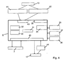
- the regulator unit arranged in the compact unit 2 6 is shown in more detail in Fig. 4.
- the regulator unit 6 includes in addition to a microcontroller 30 with an integrated Computer unit 31 and an integrated program memory 32 also has a data memory 33.
- the Regulator unit 6 with a serial interface 34 for Connection of the interface module 5 provided.
- the serial Interface 34 is assigned an interface driver 35.
- the controller unit 6 is also available with a reset controller 36 and an operating data memory 37 in Data Connection.
- the regulator unit 6 various digital inputs and outputs 40 for connecting the Operating unit 3 and the stepping motor 17. Of the Temperature sensor 13 is via different measuring amplifier 41 and 42 and one integrated in the microcontroller 30 Analog / digital converter 40 connected to the controller unit 6.
- the different measuring amplifiers 41 and 42 are necessary distinguishable by different control accuracies To realize temperature ranges. So can an outside the usual reference temperature lying temperature range be defined, the only with a coarse regulation is provided. This usually larger temperature range can with a measuring amplifier lower resolution be provided, since the measured values as such greater differences than in the temperature range associated with a finer control is provided.
- both the Program as well as the data memory are parameterized. This is the initial parameterization of the system based on a manufacturer in the program memory 32 of Microcontroller30 filed program. According to this Program will be the whole before the first start Runtime range, until by one of two corresponding limit switch 44 marked one end of achieved mechanical adjustment range of the actuating body 21 is. The position corresponding to this one endpoint becomes saved in the data memory 33. When approached The end point of the control area is usually the reference to trade from "only" cold water.
- each one is added to the Implementation of a temperature specification approached position of Actuator or the setpoint specification corresponding to this position in the form of a constantly changing and refining histogram stored in the data memory 33.
- the mixed water heater 1 thus provides a self-learning and self-adjusting system.
- a common temperature control is in a flow chart shown in FIG. 5.
- the controller 6 acts via the stepper motor 17 on the control valve.
- a first subordinate control loop is therefore in the regulation of Actual / target position of the stepping motor 17.
- On this Control circuit initially acts on the setpoint temperature specification of Control unit 3 a.
- This superimposed control loop for Temperature control receives an actual value feedback via the temperature sensor 13 as stated, depending on detected Temperature range over the first sense amplifier 41 or the second measuring amplifier 42 acts.
- Overtemperature detection or detection of a Water loss can be used.
- the controller is a constant target size given that the stepper motor 17 immediately in a Water-absorbing terminating position moves.
- the foregoing is a method and apparatus for electronic mixing water preparation described that by means of a compact unit 2 a mixed water treatment in connection with a previously unattained Ease of use allows. Due to an optimal Coordination between the electronic regulation and the mechanical actuators will have a high control speed at the same time extremely low sensory effort reached. In essence, the entire mixed water treatment solely by means of a single temperature sensor 13 done.
- the invention also relates to an electronic Mixing water heater with a control unit 3 for setpoint input and an electronic control unit 6, which in Dependence on a temperature sensor 13 for actual value detection via a mechanical actuator 17 to a Controlled system for mixed water preparation acts. It can be provided according to the invention that the electronic Regulator unit 6 and the mechanical actuator 17 in one single compact unit 2, for flush mounting is suitable, are arranged.
- the actuator a rotatably mounted actuating body acts, so that a its rotational position corresponding water mixture of a hot water inlet and a cold water feed can be fed Hot and cold water within the mixer body can be generated.
- This can be an electronic mixing water heater 1, which is characterized by a minimal Space especially suitable for flush mounting, where particularly fast reaction or switching times as well as favorable sealing and wear conditions can be achieved are.
- a stepping motor 17th is provided, which via a transmission 20 with a two-way mixer valve 21 in a mixer body 8 in operative connection stands, wherein the mixer body 8 each a cold and Hot water supply 10 and 11 has. It is therefore appropriate if as actuator of the controlled system a stepper motor 17 is provided, which via a gear 20 to a Two-way mixer valve 21 acts.
- This arrangement has the advantage that the predetermined controlled variable by means of described actuator immediately and clearly is implemented. This represents a significant improvement compared to the otherwise usual expansion elements or Bimetallic discs for mixed water control dar.
- the last mentioned actuators operate temperature-dependent, so that the behavior of the controller varies depending on the set Temperature can change.
- the regulator unit 6 comprises a Microcontroller 30 with its own computer unit 31, as well a writable data and program memory 32, 33, wherein the controller unit 6 with an interface module. 5 for connecting diagnostic and / or programming devices connected is.
- the electronic mixing water heater 1 is thus advantageously with an interface module 5 for connection connected by diagnostic and / or programming devices.
- the Interface module 5 can either be used for fault diagnosis, Paramatrtechnik or for storage of necessary Control programs are used.
- the interface module 5 may also be a remote control of the electronic Allow mixing water preparation. The remote control can doing so by means of conductive connection or with an infrared or Radio control done. Via the interface module 5 can also support the plaster-mounted system respectively.
- control unit 3 a display 26, preferably a display, and a Input unit, preferably a keypad 23, 24, 25th includes.
- each alphanumeric Character is designed as a seven-segment display.
- This display is essentially for displaying the target and / or Actual temperature used.
- the control unit also has the simplest design a menu key and two selection keys.
- the display 26 at least three alphanumeric characters, preferably each with a seven-segment display, as well as the input unit a menu key 23 and at least two selection keys 24 and 25 has.
- one or more Water supply units to the electronic mixing water heater 1 are connectable and individual water supply units can be selected and controlled via the control unit 3.
Abstract
Description
- Fig. 1
- Eine Prinzipdarstellung eines elektronischen Mischwassserbereiters im Blockschaltbild;
- Fig. 2
- eine Geräteeinheit zur Mischwasserbereitung im Querschnitt;
- Fig. 3
- eine Bedieneinheit des Mischwasserbereiters;
- Fig. 4
- ein Blockschaltbild der Reglereinheit mit Ein- und Ausgängen und
- Fig. 5
- ein Flußdiagramm zur Temperaturregelung.
Claims (8)
- Verfahren zur Mischwasserbereitung, bei dem ein über eine Bedieneinheit (3) vorgebbarer Soll-Wert über eine elektronische Reglereinheit (6) in Abhängigkeit von einem mittels eines Temperatursensors (13) erfaßten Ist-Werts mittels eines mechanischen Stellgliedes (17) auf eine Regelstrecke zur Mischwasserbereitung einwirkt, wobei das Bezugswasser, dessen Soll-Temperatur über die Bedieneinheit (3) vorgebbar ist, ausschließlich mittels des Temperatursensors (13) zur Ist-Wert-Erfassung abgemischt wird,
dadurch gekennzeichnet, daß
zusätzlich eine Gradientenauswertung des mittels des Temperatursensors (13) erfaßten Temperaturverlaufs vorgenommen wird, so daß eine Durchflußerkennung möglich ist, und wobei die Nachführung des Stellgliedes (17) abgeschaltet wird, sobald und solange der Gradient des Temperaturverlaufs einen vorgebbaren Schwellwert unterschreitet. - Verfahren nach Anspruch 1, dadurch gekennzeichnet, daß das Regelverfahren zwischen zwei Temperaturregelbereichen unterschiedlicher Regelgenauigkeit unterscheidet.
- Verfahren nach Anspruch 2, dadurch gekennzeichnet, daß die Nachführung des Stellgliedes (17) außerhalb eines definierten Temperaturbereiches abgeschaltet wird.
- Verfahren nach einem der vorhergehenden Ansprüche,
dadurch gekennzeichnet, daß die Gradientenauswertung des Temperaturverlaufs für eine Übertemperaturerkennung und/oder eine Wasserausfallserkennung derart genutzt wird, daß im Falle der Erkennung des einen und/oder anderen Ereignisses dem Regler eine Regelkonstante derart vorgegeben wird, daß das Stellglied (17) in eine den Wasserbezug unterbrechende Endstellung verfahren wird. - Verfahren nach einem der vorhergehenden Ansprüche,
dadurch gekennzeichnet, daß die Reglereinheit (6) selbst derart selbstparametrierend ausgelegt ist, daß in einem ersten Schritt ein Mininmal- und/oder Maximalpunkt des Regelbereichs, vorzugsweise der Kaltwasserzufuhr, angefahren wird und die dieser Stellgliedstellung ensprechende Sollwertvorgabe in einem Datenspeicher (33) abgelegt wird und im weiteren Betrieb die den jeweiligen Temperatureinstellungen entsprechenden Stellgliedstellungen ständig in diesem Datenspeicher (33) in einem Histogramm gespeichert und dieses hierdurch ständig aktualisiert werden. - Verfahren nach Anspruch 5, dadurch gekennzeichnet, daß im Datenspeicher (33) der Reglereinheit (6) unterschiedliche Temperaturbereiche der Feinregelung angelegt sind.
- Verfahren nach einem der vorhergehenden Ansprüche,
dadurch gekennzeichnet, daß die Reglereinheit (6) mit einer Betriebsdatenerfassung verbunden ist. - Verfahren nach einem der vorhergehenden Ansprüche,
dadurch gekennzeichnet, daß im Programmspeicher (32) der Reglereinheit (6) ein Programmm-Modul zur thermischen Desinfektion derart abgelegt ist, daß aufgrund der Programmvorgabe ein extrem hoher Temperatursollwert für einen definierten Zeitraum dem Regler vorgegeben wird.
Priority Applications (1)
| Application Number | Priority Date | Filing Date | Title |
|---|---|---|---|
| SI200030476T SI1293855T1 (en) | 1999-12-18 | 2000-12-13 | Method foe preparing mixed water |
Applications Claiming Priority (3)
| Application Number | Priority Date | Filing Date | Title |
|---|---|---|---|
| DE19961183A DE19961183A1 (de) | 1999-12-18 | 1999-12-18 | Elektronischer Mischwasserbereiter und Verfahren zur Mischwasserbereitung |
| DE19961183 | 1999-12-18 | ||
| EP00990591A EP1240564B1 (de) | 1999-12-18 | 2000-12-13 | Elektronischer mischwasserbereiter und verfahren zur mischwasserbereitung |
Related Parent Applications (2)
| Application Number | Title | Priority Date | Filing Date |
|---|---|---|---|
| EP00990591.0 Division | 2000-12-13 | ||
| EP00990591A Division EP1240564B1 (de) | 1999-12-18 | 2000-12-13 | Elektronischer mischwasserbereiter und verfahren zur mischwasserbereitung |
Publications (3)
| Publication Number | Publication Date |
|---|---|
| EP1293855A2 true EP1293855A2 (de) | 2003-03-19 |
| EP1293855A3 EP1293855A3 (de) | 2004-01-02 |
| EP1293855B1 EP1293855B1 (de) | 2004-08-18 |
Family
ID=7933224
Family Applications (2)
| Application Number | Title | Priority Date | Filing Date |
|---|---|---|---|
| EP00990591A Expired - Lifetime EP1240564B1 (de) | 1999-12-18 | 2000-12-13 | Elektronischer mischwasserbereiter und verfahren zur mischwasserbereitung |
| EP02027886A Expired - Lifetime EP1293855B1 (de) | 1999-12-18 | 2000-12-13 | Verfahren zur Mischwasserbereitung |
Family Applications Before (1)
| Application Number | Title | Priority Date | Filing Date |
|---|---|---|---|
| EP00990591A Expired - Lifetime EP1240564B1 (de) | 1999-12-18 | 2000-12-13 | Elektronischer mischwasserbereiter und verfahren zur mischwasserbereitung |
Country Status (17)
| Country | Link |
|---|---|
| US (2) | US6688530B2 (de) |
| EP (2) | EP1240564B1 (de) |
| JP (1) | JP4819274B2 (de) |
| KR (1) | KR100743799B1 (de) |
| CN (1) | CN1259604C (de) |
| AT (2) | ATE274202T1 (de) |
| AU (1) | AU3002101A (de) |
| BG (1) | BG65392B1 (de) |
| DE (4) | DE19961183A1 (de) |
| DK (2) | DK1293855T3 (de) |
| ES (2) | ES2227382T3 (de) |
| IL (2) | IL150073A0 (de) |
| PL (1) | PL198219B1 (de) |
| PT (1) | PT1293855E (de) |
| SI (2) | SI1293855T1 (de) |
| TR (1) | TR200402244T4 (de) |
| WO (1) | WO2001044884A2 (de) |
Cited By (1)
| Publication number | Priority date | Publication date | Assignee | Title |
|---|---|---|---|---|
| EP1605327A3 (de) * | 2004-06-09 | 2009-01-21 | Hansa Metallwerke Ag | Sanitäres Thermostatventil |
Families Citing this family (41)
| Publication number | Priority date | Publication date | Assignee | Title |
|---|---|---|---|---|
| DE10219171A1 (de) * | 2002-04-30 | 2003-11-13 | Kludi Gmbh & Co Kg | Einhebelarmatur |
| US6913203B2 (en) * | 2003-12-03 | 2005-07-05 | Delangis Eric | Self powered electronically controlled mixing valve |
| US20050125699A1 (en) * | 2003-12-05 | 2005-06-09 | Raymond Harper | Sarts password manager |
| US7690395B2 (en) | 2004-01-12 | 2010-04-06 | Masco Corporation Of Indiana | Multi-mode hands free automatic faucet |
| US8225961B2 (en) * | 2004-08-25 | 2012-07-24 | Bunn-O-Matic Corporation | Multiple hot water dispensing system |
| GB0500970D0 (en) * | 2005-01-18 | 2005-02-23 | Kohler Mira Ltd | Improvements in or relating to ablutionary Installations |
| US7867172B1 (en) | 2006-11-09 | 2011-01-11 | Dingane Baruti | Combination toothbrush and peak flow meter system |
| US8438672B2 (en) | 2005-11-11 | 2013-05-14 | Masco Corporation Of Indiana | Integrated electronic shower system |
| US20080000997A1 (en) * | 2006-03-03 | 2008-01-03 | Duane Smith | Safe-T-Shower |
| US8162236B2 (en) | 2006-04-20 | 2012-04-24 | Masco Corporation Of Indiana | Electronic user interface for electronic mixing of water for residential faucets |
| US9243756B2 (en) | 2006-04-20 | 2016-01-26 | Delta Faucet Company | Capacitive user interface for a faucet and method of forming |
| US8089473B2 (en) | 2006-04-20 | 2012-01-03 | Masco Corporation Of Indiana | Touch sensor |
| US8365767B2 (en) | 2006-04-20 | 2013-02-05 | Masco Corporation Of Indiana | User interface for a faucet |
| US8118240B2 (en) | 2006-04-20 | 2012-02-21 | Masco Corporation Of Indiana | Pull-out wand |
| US9243392B2 (en) | 2006-12-19 | 2016-01-26 | Delta Faucet Company | Resistive coupling for an automatic faucet |
| US7806141B2 (en) | 2007-01-31 | 2010-10-05 | Masco Corporation Of Indiana | Mixing valve including a molded waterway assembly |
| WO2008094651A1 (en) | 2007-01-31 | 2008-08-07 | Masco Corporation Of Indiana | Capacitive sensing apparatus and method for faucets |
| WO2008118402A1 (en) | 2007-03-28 | 2008-10-02 | Masco Corporation Of Indiana | Improved capacitive touch sensor |
| US7665483B1 (en) | 2007-10-25 | 2010-02-23 | Alberto Sid | Motorized shower diverter system |
| CA2708577C (en) | 2007-12-11 | 2014-08-05 | Masco Corporation Of Indiana | Capacitive coupling arrangement for a faucet |
| US7934662B1 (en) | 2008-02-15 | 2011-05-03 | Robert Jenkins | Thermostatic water mixing unit |
| US20100032488A1 (en) * | 2008-08-06 | 2010-02-11 | Garry Edward Yates | Mixing Valve Control System |
| US20110004994A1 (en) * | 2009-07-13 | 2011-01-13 | Luraco Technologies, Inc. | Apparatus, system and method for multi-function intelligent spa control |
| US8193659B2 (en) * | 2009-11-19 | 2012-06-05 | Ormat Technologies, Inc. | Power system |
| US8561626B2 (en) | 2010-04-20 | 2013-10-22 | Masco Corporation Of Indiana | Capacitive sensing system and method for operating a faucet |
| US8776817B2 (en) | 2010-04-20 | 2014-07-15 | Masco Corporation Of Indiana | Electronic faucet with a capacitive sensing system and a method therefor |
| CA3096237C (en) | 2010-11-04 | 2023-01-24 | Magarl, Llc | Electrohydraulic thermostatic control valve |
| CH704187B1 (de) | 2010-12-06 | 2021-11-15 | Eliane Zoccolillo Luethi | Sanitärsystem mit einer Mischzentrale. |
| DE202011000038U1 (de) * | 2011-01-07 | 2012-04-16 | Lindner Armaturen Gmbh | Elektronische Sanitärarmatur, insbesondere für Waschtische |
| CN204199385U (zh) | 2012-03-07 | 2015-03-11 | 莫恩股份有限公司 | 电子卫生器具配件 |
| IN2014DN08503A (de) | 2012-04-20 | 2015-05-15 | Masco Corp | |
| NL2008698C2 (nl) | 2012-04-24 | 2013-10-28 | Henri Peteri Beheer Bv | Afgifteinrichting voor water. |
| US9574331B2 (en) * | 2012-06-18 | 2017-02-21 | Kenneth McLeod Wright | Shower flow monitor and display |
| CN103498949B (zh) * | 2013-09-11 | 2015-09-30 | 山东齿兴机械制造有限公司 | 冷热水混合恒温控制器 |
| FR3019914B1 (fr) * | 2014-04-14 | 2016-05-13 | Vernet | Procede de determination d'une loi de commande d'une vanne d'une cartouche thermostatique electronique, cartouche et mitigeur associes |
| CN103970163B (zh) * | 2014-05-14 | 2016-04-20 | 福州锐洁源电子科技有限公司 | 一种可调节温度供水系统及其使用方法 |
| CN104932295A (zh) * | 2015-04-29 | 2015-09-23 | 厦门建霖工业有限公司 | 一种多功能淋浴人性化控制方法 |
| CN105867456A (zh) * | 2016-04-01 | 2016-08-17 | 安庆市鸿裕工业产品设计有限公司 | 一种电子控温接口组件 |
| CN106037556B (zh) * | 2016-08-05 | 2018-05-25 | 无锡同春新能源科技有限公司 | 一种可以显示并调控汤水温度的智能泡脚桶 |
| EP3924651B1 (de) | 2019-02-14 | 2024-03-20 | Viega Technology GmbH & Co. KG | Funktionseinheit |
| DE102019203163A1 (de) | 2019-03-08 | 2020-09-10 | Hansgrohe Se | Sanitäre Dusch-/Wascheinrichtung mit Dusch-/Waschprogrammbereitstellung |
Citations (5)
| Publication number | Priority date | Publication date | Assignee | Title |
|---|---|---|---|---|
| GB2056627A (en) * | 1979-08-14 | 1981-03-18 | Crosweller & Co Ltd W | Mixing valve |
| US4646964A (en) * | 1982-03-26 | 1987-03-03 | Parker Electronics, Inc. | Temperature control system |
| DE4026110A1 (de) * | 1990-08-17 | 1992-02-20 | Grohe Armaturen Friedrich | Vorrichtung zur regelung und bedienung einer mischwasserbereitungsanlage |
| DE4401637A1 (de) * | 1993-01-22 | 1994-07-28 | Grohe Kg Hans | Sanitäre Mischarmatur |
| US5588636A (en) * | 1994-06-10 | 1996-12-31 | Friedrich Grohe Aktiengesellschaft | Water fixture control system |
Family Cites Families (21)
| Publication number | Priority date | Publication date | Assignee | Title |
|---|---|---|---|---|
| DE8314239U1 (de) * | 1983-05-13 | 1983-09-15 | Getronik elektronische Geräte GmbH, 3002 Wedemark | Beruehrungsglos betaetigbare armatur |
| GB2143343A (en) * | 1983-07-13 | 1985-02-06 | Standard Telephones Cables Ltd | Thermostatically controlled mixer |
| NO152880C (no) * | 1983-08-30 | 1985-12-04 | Lyng Ind As | Temperaturpaavirkbar, elektronisk styrt blandeventil for blanding av to vaesker. |
| DE3518644A1 (de) * | 1985-05-23 | 1986-11-27 | Knebel & Röttger GmbH & Co, 5860 Iserlohn | Sanitaer-mischarmatur |
| US4696428A (en) * | 1986-07-10 | 1987-09-29 | Paul Shakalis | Electronic fluid temperature flow control system |
| DE3624799A1 (de) * | 1986-07-23 | 1988-01-28 | Ideal Standard | Elektronisch temperaturgeregelte mischarmatur |
| IL80806A0 (en) * | 1986-11-28 | 1987-02-27 | Avraham Kochal | Faucet mixing battery |
| US5361215A (en) * | 1987-05-27 | 1994-11-01 | Siege Industries, Inc. | Spa control system |
| DE3718039C2 (de) * | 1987-05-28 | 1994-04-21 | Ideal Standard | Elektronisch temperaturgeregelte Mischarmatur |
| GB8715717D0 (en) * | 1987-07-03 | 1987-08-12 | Armitage Shanks Ltd | Thermostatic valves |
| US4875623A (en) * | 1987-07-17 | 1989-10-24 | Memrysafe, Inc. | Valve control |
| DE3739676A1 (de) * | 1987-11-24 | 1989-06-08 | Eckerfeld Erika | Durchlauferhitzer mit elektronischer temperaturregelung |
| DE3838046A1 (de) * | 1988-11-09 | 1990-05-10 | Butzke Werke Aqua | Verfahren zum thermischen desinfizieren |
| US4941608A (en) * | 1988-12-23 | 1990-07-17 | Matsushita Electric Works, Ltd. | Hot water supplying system |
| US4923116A (en) * | 1989-05-24 | 1990-05-08 | Homan Gerald L | Bath water control system |
| DE4430805A1 (de) * | 1993-09-01 | 1995-05-11 | Desch Kurt Michael | Elektronische Badewannen/Brause Armatur |
| JPH08123555A (ja) * | 1994-10-24 | 1996-05-17 | Matsushita Electric Ind Co Ltd | 湯水混合装置 |
| US5944255A (en) * | 1997-08-29 | 1999-08-31 | Shirmohamadi; Manuchehr | Shower water automatic temperature controller |
| US5979775A (en) * | 1998-01-23 | 1999-11-09 | Raya; Richard | Bathing water pre-mixing system |
| GB2335512A (en) * | 1998-03-16 | 1999-09-22 | Su Chao Ta | A water temperature detecting and controlling device |
| US6286764B1 (en) * | 1999-07-14 | 2001-09-11 | Edward C. Garvey | Fluid and gas supply system |
-
1999
- 1999-12-18 DE DE19961183A patent/DE19961183A1/de not_active Withdrawn
-
2000
- 2000-12-13 SI SI200030476T patent/SI1293855T1/xx unknown
- 2000-12-13 AT AT02027886T patent/ATE274202T1/de not_active IP Right Cessation
- 2000-12-13 PT PT02027886T patent/PT1293855E/pt unknown
- 2000-12-13 ES ES02027886T patent/ES2227382T3/es not_active Expired - Lifetime
- 2000-12-13 WO PCT/DE2000/004680 patent/WO2001044884A2/de active IP Right Grant
- 2000-12-13 US US10/149,957 patent/US6688530B2/en not_active Expired - Lifetime
- 2000-12-13 IL IL15007300A patent/IL150073A0/xx active IP Right Grant
- 2000-12-13 TR TR2004/02244T patent/TR200402244T4/xx unknown
- 2000-12-13 DE DE50003588T patent/DE50003588D1/de not_active Expired - Lifetime
- 2000-12-13 KR KR1020027007792A patent/KR100743799B1/ko not_active IP Right Cessation
- 2000-12-13 PL PL355674A patent/PL198219B1/pl unknown
- 2000-12-13 DK DK02027886T patent/DK1293855T3/da active
- 2000-12-13 SI SI200030212T patent/SI1240564T1/xx unknown
- 2000-12-13 EP EP00990591A patent/EP1240564B1/de not_active Expired - Lifetime
- 2000-12-13 JP JP2001545912A patent/JP4819274B2/ja not_active Expired - Fee Related
- 2000-12-13 DE DE50007522T patent/DE50007522D1/de not_active Expired - Lifetime
- 2000-12-13 AU AU30021/01A patent/AU3002101A/en not_active Abandoned
- 2000-12-13 DK DK00990591T patent/DK1240564T3/da active
- 2000-12-13 CN CNB008173508A patent/CN1259604C/zh not_active Expired - Fee Related
- 2000-12-13 DE DE10083966T patent/DE10083966D2/de not_active Withdrawn - After Issue
- 2000-12-13 AT AT00990591T patent/ATE249067T1/de not_active IP Right Cessation
- 2000-12-13 EP EP02027886A patent/EP1293855B1/de not_active Expired - Lifetime
- 2000-12-13 ES ES00990591T patent/ES2206349T3/es not_active Expired - Lifetime
-
2002
- 2002-06-06 IL IL150073A patent/IL150073A/en not_active IP Right Cessation
- 2002-06-06 BG BG106781A patent/BG65392B1/bg unknown
-
2004
- 2004-02-05 US US10/772,906 patent/US20040155116A1/en not_active Abandoned
Patent Citations (5)
| Publication number | Priority date | Publication date | Assignee | Title |
|---|---|---|---|---|
| GB2056627A (en) * | 1979-08-14 | 1981-03-18 | Crosweller & Co Ltd W | Mixing valve |
| US4646964A (en) * | 1982-03-26 | 1987-03-03 | Parker Electronics, Inc. | Temperature control system |
| DE4026110A1 (de) * | 1990-08-17 | 1992-02-20 | Grohe Armaturen Friedrich | Vorrichtung zur regelung und bedienung einer mischwasserbereitungsanlage |
| DE4401637A1 (de) * | 1993-01-22 | 1994-07-28 | Grohe Kg Hans | Sanitäre Mischarmatur |
| US5588636A (en) * | 1994-06-10 | 1996-12-31 | Friedrich Grohe Aktiengesellschaft | Water fixture control system |
Cited By (1)
| Publication number | Priority date | Publication date | Assignee | Title |
|---|---|---|---|---|
| EP1605327A3 (de) * | 2004-06-09 | 2009-01-21 | Hansa Metallwerke Ag | Sanitäres Thermostatventil |
Also Published As
Similar Documents
| Publication | Publication Date | Title |
|---|---|---|
| EP1293855B1 (de) | Verfahren zur Mischwasserbereitung | |
| EP2218840B1 (de) | Sanitärarmatur mit Joysticksteuerung | |
| EP1249544A1 (de) | Vorrichtung zur Steuerung der Wannenbefüllung einer Sanitärwanne | |
| DE60217198T2 (de) | Vorrichtung mit einem Wassermischventil | |
| DE60126855T2 (de) | Lehrsteuerpult für Roboter | |
| EP1033641A1 (de) | Steuereinrichtung für eine Heizeinrichtung | |
| AT400484B (de) | Regel- und steuersystem für einen vorzugsweise gasbeheizten wassererhitzer | |
| DE4107860C2 (de) | ||
| DE4203613C2 (de) | Steuersystem für Raumheizanlagen | |
| DE3430176A1 (de) | Vorrichtung zum mischen von heissem und kaltem wasser | |
| DE3425445A1 (de) | Elektronischer mischwasserthermostat mit robustem regelverhalten | |
| DE4401637A1 (de) | Sanitäre Mischarmatur | |
| EP0876643A1 (de) | Wasserentnahmesystem | |
| EP3696332B1 (de) | Elektrisch betreibbare sanitärarmatur | |
| DE2939586C2 (de) | Verfahren und Anordnung zur Regelupng der Wassertemperatur von Warmwasser-Flächenheizungen mit Nachtabsenkung | |
| DE3509353C1 (de) | Regeleinrichtung für ein Thermostatventil | |
| DE102008013946B3 (de) | Verfahren zum Steuern eines elektrischen Durchlauferhitzers | |
| DE10031665B4 (de) | Elektronisch steuerbare Armatur für eine Sanitärwanne | |
| DE4447893C2 (de) | Sanitäre Mischarmatur | |
| DE10226736A1 (de) | Wasserzulauf für ein Haushaltsgerät | |
| DE2145096C (de) | Einrichtung zur automatischen Mahlspalt-Steuerung bei einer Mühle | |
| DE19725832C1 (de) | Verfahren und Einrichtung zum Erzeugen einer Wasser-in-Dieselöl-Emulsion | |
| EP2169124A2 (de) | Elektronisch steuerbare Armatur zum Mischen von kaltem und warmen Wasser, insbesondere für einen Waschtisch | |
| DE3110233A1 (de) | Elektronische temperaturregelung fuer heizungsanlagen | |
| DE10140192C1 (de) | Regeleinrichtung für Gebäude |
Legal Events
| Date | Code | Title | Description |
|---|---|---|---|
| PUAI | Public reference made under article 153(3) epc to a published international application that has entered the european phase |
Free format text: ORIGINAL CODE: 0009012 |
|
| AC | Divisional application: reference to earlier application |
Ref document number: 1240564 Country of ref document: EP Kind code of ref document: P |
|
| AK | Designated contracting states |
Designated state(s): AT BE CH CY DE DK ES FI FR GB GR IE IT LI LU MC NL PT SE TR Kind code of ref document: A2 Designated state(s): AT BE CH CY DE DK ES FI FR GB GR IE IT LI LU MC NL PT SE TR |
|
| AX | Request for extension of the european patent |
Extension state: AL LT LV MK RO SI |
|
| PUAL | Search report despatched |
Free format text: ORIGINAL CODE: 0009013 |
|
| AK | Designated contracting states |
Kind code of ref document: A3 Designated state(s): AT BE CH CY DE DK ES FI FR GB GR IE IT LI LU MC NL PT SE TR |
|
| AX | Request for extension of the european patent |
Extension state: AL LT LV MK RO SI |
|
| 17P | Request for examination filed |
Effective date: 20031128 |
|
| GRAP | Despatch of communication of intention to grant a patent |
Free format text: ORIGINAL CODE: EPIDOSNIGR1 |
|
| GRAS | Grant fee paid |
Free format text: ORIGINAL CODE: EPIDOSNIGR3 |
|
| GRAA | (expected) grant |
Free format text: ORIGINAL CODE: 0009210 |
|
| AC | Divisional application: reference to earlier application |
Ref document number: 1240564 Country of ref document: EP Kind code of ref document: P |
|
| AK | Designated contracting states |
Kind code of ref document: B1 Designated state(s): AT BE CH CY DE DK ES FI FR GB GR IE IT LI LU MC NL PT SE TR |
|
| AX | Request for extension of the european patent |
Extension state: AL LT LV MK RO SI |
|
| PG25 | Lapsed in a contracting state [announced via postgrant information from national office to epo] |
Ref country code: CY Free format text: LAPSE BECAUSE OF FAILURE TO SUBMIT A TRANSLATION OF THE DESCRIPTION OR TO PAY THE FEE WITHIN THE PRESCRIBED TIME-LIMIT Effective date: 20040818 Ref country code: IE Free format text: LAPSE BECAUSE OF FAILURE TO SUBMIT A TRANSLATION OF THE DESCRIPTION OR TO PAY THE FEE WITHIN THE PRESCRIBED TIME-LIMIT Effective date: 20040818 |
|
| REG | Reference to a national code |
Ref country code: GB Ref legal event code: FG4D Free format text: NOT ENGLISH |
|
| REG | Reference to a national code |
Ref country code: CH Ref legal event code: EP |
|
| GBT | Gb: translation of ep patent filed (gb section 77(6)(a)/1977) |
Effective date: 20040818 |
|
| REG | Reference to a national code |
Ref country code: SE Ref legal event code: TRGR |
|
| AKX | Designation fees paid |
Designated state(s): AT BE CH CY DE DK ES FI FR GB GR IE IT LI LU MC NL PT SE TR |
|
| REG | Reference to a national code |
Ref country code: IE Ref legal event code: FG4D Free format text: GERMAN |
|
| REF | Corresponds to: |
Ref document number: 50007522 Country of ref document: DE Date of ref document: 20040923 Kind code of ref document: P |
|
| REG | Reference to a national code |
Ref country code: CH Ref legal event code: NV Representative=s name: TROESCH SCHEIDEGGER WERNER AG |
|
| REG | Reference to a national code |
Ref country code: DK Ref legal event code: T3 |
|
| PG25 | Lapsed in a contracting state [announced via postgrant information from national office to epo] |
Ref country code: GR Free format text: LAPSE BECAUSE OF FAILURE TO SUBMIT A TRANSLATION OF THE DESCRIPTION OR TO PAY THE FEE WITHIN THE PRESCRIBED TIME-LIMIT Effective date: 20041118 |
|
| REG | Reference to a national code |
Ref country code: PT Ref legal event code: SC4A Free format text: AVAILABILITY OF NATIONAL TRANSLATION Effective date: 20040916 |
|
| PG25 | Lapsed in a contracting state [announced via postgrant information from national office to epo] |
Ref country code: LU Free format text: LAPSE BECAUSE OF NON-PAYMENT OF DUE FEES Effective date: 20041213 |
|
| PG25 | Lapsed in a contracting state [announced via postgrant information from national office to epo] |
Ref country code: MC Free format text: LAPSE BECAUSE OF NON-PAYMENT OF DUE FEES Effective date: 20041231 |
|
| REG | Reference to a national code |
Ref country code: SI Ref legal event code: IF |
|
| LTIE | Lt: invalidation of european patent or patent extension |
Effective date: 20040818 |
|
| ET | Fr: translation filed | ||
| REG | Reference to a national code |
Ref country code: IE Ref legal event code: FD4D |
|
| REG | Reference to a national code |
Ref country code: ES Ref legal event code: FG2A Ref document number: 2227382 Country of ref document: ES Kind code of ref document: T3 |
|
| PLBE | No opposition filed within time limit |
Free format text: ORIGINAL CODE: 0009261 |
|
| STAA | Information on the status of an ep patent application or granted ep patent |
Free format text: STATUS: NO OPPOSITION FILED WITHIN TIME LIMIT |
|
| 26N | No opposition filed |
Effective date: 20050519 |
|
| PGFP | Annual fee paid to national office [announced via postgrant information from national office to epo] |
Ref country code: NL Payment date: 20071231 Year of fee payment: 8 |
|
| PGFP | Annual fee paid to national office [announced via postgrant information from national office to epo] |
Ref country code: PT Payment date: 20071207 Year of fee payment: 8 |
|
| PGFP | Annual fee paid to national office [announced via postgrant information from national office to epo] |
Ref country code: BE Payment date: 20071231 Year of fee payment: 8 |
|
| PGFP | Annual fee paid to national office [announced via postgrant information from national office to epo] |
Ref country code: DK Payment date: 20081218 Year of fee payment: 9 Ref country code: TR Payment date: 20081212 Year of fee payment: 9 |
|
| PGFP | Annual fee paid to national office [announced via postgrant information from national office to epo] |
Ref country code: AT Payment date: 20081223 Year of fee payment: 9 |
|
| PGFP | Annual fee paid to national office [announced via postgrant information from national office to epo] |
Ref country code: SE Payment date: 20081222 Year of fee payment: 9 |
|
| REG | Reference to a national code |
Ref country code: PT Ref legal event code: MM4A Free format text: LAPSE DUE TO NON-PAYMENT OF FEES Effective date: 20090615 |
|
| BERE | Be: lapsed |
Owner name: *INNOTECH ELECTRONIC G.M.B.H. Effective date: 20081231 |
|
| PGFP | Annual fee paid to national office [announced via postgrant information from national office to epo] |
Ref country code: CH Payment date: 20090224 Year of fee payment: 9 |
|
| PG25 | Lapsed in a contracting state [announced via postgrant information from national office to epo] |
Ref country code: PT Free format text: LAPSE BECAUSE OF NON-PAYMENT OF DUE FEES Effective date: 20090615 |
|
| NLV4 | Nl: lapsed or anulled due to non-payment of the annual fee |
Effective date: 20090701 |
|
| PG25 | Lapsed in a contracting state [announced via postgrant information from national office to epo] |
Ref country code: BE Free format text: LAPSE BECAUSE OF NON-PAYMENT OF DUE FEES Effective date: 20081231 |
|
| REG | Reference to a national code |
Ref country code: SI Ref legal event code: KO00 Effective date: 20090803 |
|
| PG25 | Lapsed in a contracting state [announced via postgrant information from national office to epo] |
Ref country code: NL Free format text: LAPSE BECAUSE OF NON-PAYMENT OF DUE FEES Effective date: 20090701 |
|
| EUG | Se: european patent has lapsed | ||
| REG | Reference to a national code |
Ref country code: CH Ref legal event code: PL |
|
| REG | Reference to a national code |
Ref country code: DK Ref legal event code: EBP |
|
| PG25 | Lapsed in a contracting state [announced via postgrant information from national office to epo] |
Ref country code: AT Free format text: LAPSE BECAUSE OF NON-PAYMENT OF DUE FEES Effective date: 20091213 |
|
| PG25 | Lapsed in a contracting state [announced via postgrant information from national office to epo] |
Ref country code: CH Free format text: LAPSE BECAUSE OF NON-PAYMENT OF DUE FEES Effective date: 20091231 Ref country code: LI Free format text: LAPSE BECAUSE OF NON-PAYMENT OF DUE FEES Effective date: 20091231 |
|
| PG25 | Lapsed in a contracting state [announced via postgrant information from national office to epo] |
Ref country code: DK Free format text: LAPSE BECAUSE OF NON-PAYMENT OF DUE FEES Effective date: 20100104 |
|
| PG25 | Lapsed in a contracting state [announced via postgrant information from national office to epo] |
Ref country code: SE Free format text: LAPSE BECAUSE OF NON-PAYMENT OF DUE FEES Effective date: 20091214 |
|
| PGFP | Annual fee paid to national office [announced via postgrant information from national office to epo] |
Ref country code: GB Payment date: 20110128 Year of fee payment: 11 |
|
| PGFP | Annual fee paid to national office [announced via postgrant information from national office to epo] |
Ref country code: FR Payment date: 20120103 Year of fee payment: 12 Ref country code: ES Payment date: 20111219 Year of fee payment: 12 Ref country code: FI Payment date: 20111219 Year of fee payment: 12 |
|
| PGFP | Annual fee paid to national office [announced via postgrant information from national office to epo] |
Ref country code: IT Payment date: 20111228 Year of fee payment: 12 |
|
| PG25 | Lapsed in a contracting state [announced via postgrant information from national office to epo] |
Ref country code: TR Free format text: LAPSE BECAUSE OF NON-PAYMENT OF DUE FEES Effective date: 20091213 |
|
| GBPC | Gb: european patent ceased through non-payment of renewal fee |
Effective date: 20121213 |
|
| PG25 | Lapsed in a contracting state [announced via postgrant information from national office to epo] |
Ref country code: FI Free format text: LAPSE BECAUSE OF NON-PAYMENT OF DUE FEES Effective date: 20121213 |
|
| REG | Reference to a national code |
Ref country code: FR Ref legal event code: ST Effective date: 20130830 |
|
| PG25 | Lapsed in a contracting state [announced via postgrant information from national office to epo] |
Ref country code: GB Free format text: LAPSE BECAUSE OF NON-PAYMENT OF DUE FEES Effective date: 20121213 Ref country code: FR Free format text: LAPSE BECAUSE OF NON-PAYMENT OF DUE FEES Effective date: 20130102 |
|
| PG25 | Lapsed in a contracting state [announced via postgrant information from national office to epo] |
Ref country code: IT Free format text: LAPSE BECAUSE OF NON-PAYMENT OF DUE FEES Effective date: 20121213 |
|
| REG | Reference to a national code |
Ref country code: ES Ref legal event code: FD2A Effective date: 20140306 |
|
| PG25 | Lapsed in a contracting state [announced via postgrant information from national office to epo] |
Ref country code: ES Free format text: LAPSE BECAUSE OF NON-PAYMENT OF DUE FEES Effective date: 20121214 |
|
| PGFP | Annual fee paid to national office [announced via postgrant information from national office to epo] |
Ref country code: DE Payment date: 20141231 Year of fee payment: 15 |
|
| REG | Reference to a national code |
Ref country code: DE Ref legal event code: R119 Ref document number: 50007522 Country of ref document: DE |
|
| PG25 | Lapsed in a contracting state [announced via postgrant information from national office to epo] |
Ref country code: DE Free format text: LAPSE BECAUSE OF NON-PAYMENT OF DUE FEES Effective date: 20160701 |