EP1296803B1 - Method of making a surface treating article and such a surface treating article - Google Patents
Method of making a surface treating article and such a surface treating article Download PDFInfo
- Publication number
- EP1296803B1 EP1296803B1 EP00983771A EP00983771A EP1296803B1 EP 1296803 B1 EP1296803 B1 EP 1296803B1 EP 00983771 A EP00983771 A EP 00983771A EP 00983771 A EP00983771 A EP 00983771A EP 1296803 B1 EP1296803 B1 EP 1296803B1
- Authority
- EP
- European Patent Office
- Prior art keywords
- surface treating
- fastener
- web
- fasteners
- article
- Prior art date
- Legal status (The legal status is an assumption and is not a legal conclusion. Google has not performed a legal analysis and makes no representation as to the accuracy of the status listed.)
- Expired - Lifetime
Links
- 238000004519 manufacturing process Methods 0.000 title claims description 9
- 238000005520 cutting process Methods 0.000 claims abstract description 39
- 238000000034 method Methods 0.000 claims description 62
- 238000003466 welding Methods 0.000 claims description 20
- 239000000853 adhesive Substances 0.000 claims description 18
- 230000001070 adhesive effect Effects 0.000 claims description 18
- 238000003698 laser cutting Methods 0.000 claims description 5
- 229920001169 thermoplastic Polymers 0.000 claims description 5
- 239000004416 thermosoftening plastic Substances 0.000 claims description 5
- 238000011437 continuous method Methods 0.000 claims description 2
- 238000000926 separation method Methods 0.000 description 20
- 238000003491 array Methods 0.000 description 13
- 239000010410 layer Substances 0.000 description 11
- 230000007246 mechanism Effects 0.000 description 10
- 230000003750 conditioning effect Effects 0.000 description 8
- 239000000463 material Substances 0.000 description 8
- 229920001187 thermosetting polymer Polymers 0.000 description 6
- 239000004744 fabric Substances 0.000 description 4
- 230000008569 process Effects 0.000 description 4
- 239000012815 thermoplastic material Substances 0.000 description 4
- 230000008878 coupling Effects 0.000 description 3
- 238000010168 coupling process Methods 0.000 description 3
- 238000005859 coupling reaction Methods 0.000 description 3
- 230000003287 optical effect Effects 0.000 description 3
- 239000000758 substrate Substances 0.000 description 3
- 239000004677 Nylon Substances 0.000 description 2
- 230000001133 acceleration Effects 0.000 description 2
- 239000012790 adhesive layer Substances 0.000 description 2
- 239000002184 metal Substances 0.000 description 2
- 238000005065 mining Methods 0.000 description 2
- 229920001778 nylon Polymers 0.000 description 2
- 238000001454 recorded image Methods 0.000 description 2
- 238000005507 spraying Methods 0.000 description 2
- 239000004952 Polyamide Substances 0.000 description 1
- 229910000831 Steel Inorganic materials 0.000 description 1
- 241001147416 Ursus maritimus Species 0.000 description 1
- 239000003082 abrasive agent Substances 0.000 description 1
- 230000003213 activating effect Effects 0.000 description 1
- 230000003044 adaptive effect Effects 0.000 description 1
- 230000008901 benefit Effects 0.000 description 1
- 244000309464 bull Species 0.000 description 1
- 239000011248 coating agent Substances 0.000 description 1
- 238000000576 coating method Methods 0.000 description 1
- 238000001816 cooling Methods 0.000 description 1
- 239000000835 fiber Substances 0.000 description 1
- 230000003760 hair shine Effects 0.000 description 1
- 238000003384 imaging method Methods 0.000 description 1
- 238000007689 inspection Methods 0.000 description 1
- 238000003475 lamination Methods 0.000 description 1
- 239000011159 matrix material Substances 0.000 description 1
- 238000005259 measurement Methods 0.000 description 1
- 239000000155 melt Substances 0.000 description 1
- 230000002093 peripheral effect Effects 0.000 description 1
- 238000005498 polishing Methods 0.000 description 1
- 229920002647 polyamide Polymers 0.000 description 1
- 230000004044 response Effects 0.000 description 1
- 238000009987 spinning Methods 0.000 description 1
- 239000010959 steel Substances 0.000 description 1
- 239000002699 waste material Substances 0.000 description 1
- XLYOFNOQVPJJNP-UHFFFAOYSA-N water Substances O XLYOFNOQVPJJNP-UHFFFAOYSA-N 0.000 description 1
- 238000004804 winding Methods 0.000 description 1
Images


Classifications
-
- B—PERFORMING OPERATIONS; TRANSPORTING
- B23—MACHINE TOOLS; METAL-WORKING NOT OTHERWISE PROVIDED FOR
- B23B—TURNING; BORING
- B23B31/00—Chucks; Expansion mandrels; Adaptations thereof for remote control
- B23B31/02—Chucks
- B23B31/10—Chucks characterised by the retaining or gripping devices or their immediate operating means
- B23B31/11—Retention by threaded connection
-
- B—PERFORMING OPERATIONS; TRANSPORTING
- B24—GRINDING; POLISHING
- B24B—MACHINES, DEVICES, OR PROCESSES FOR GRINDING OR POLISHING; DRESSING OR CONDITIONING OF ABRADING SURFACES; FEEDING OF GRINDING, POLISHING, OR LAPPING AGENTS
- B24B45/00—Means for securing grinding wheels on rotary arbors
-
- B—PERFORMING OPERATIONS; TRANSPORTING
- B24—GRINDING; POLISHING
- B24D—TOOLS FOR GRINDING, BUFFING OR SHARPENING
- B24D11/00—Constructional features of flexible abrasive materials; Special features in the manufacture of such materials
- B24D11/008—Finishing manufactured abrasive sheets, e.g. cutting, deforming
-
- B—PERFORMING OPERATIONS; TRANSPORTING
- B24—GRINDING; POLISHING
- B24D—TOOLS FOR GRINDING, BUFFING OR SHARPENING
- B24D13/00—Wheels having flexibly-acting working parts, e.g. buffing wheels; Mountings therefor
- B24D13/20—Mountings for the wheels
-
- B—PERFORMING OPERATIONS; TRANSPORTING
- B24—GRINDING; POLISHING
- B24D—TOOLS FOR GRINDING, BUFFING OR SHARPENING
- B24D18/00—Manufacture of grinding tools or other grinding devices, e.g. wheels, not otherwise provided for
- B24D18/0036—Manufacture of grinding tools or other grinding devices, e.g. wheels, not otherwise provided for by winding up abrasive bands
-
- B—PERFORMING OPERATIONS; TRANSPORTING
- B24—GRINDING; POLISHING
- B24D—TOOLS FOR GRINDING, BUFFING OR SHARPENING
- B24D7/00—Bonded abrasive wheels, or wheels with inserted abrasive blocks, designed for acting otherwise than only by their periphery, e.g. by the front face; Bushings or mountings therefor
- B24D7/16—Bushings; Mountings
-
- Y—GENERAL TAGGING OF NEW TECHNOLOGICAL DEVELOPMENTS; GENERAL TAGGING OF CROSS-SECTIONAL TECHNOLOGIES SPANNING OVER SEVERAL SECTIONS OF THE IPC; TECHNICAL SUBJECTS COVERED BY FORMER USPC CROSS-REFERENCE ART COLLECTIONS [XRACs] AND DIGESTS
- Y10—TECHNICAL SUBJECTS COVERED BY FORMER USPC
- Y10T—TECHNICAL SUBJECTS COVERED BY FORMER US CLASSIFICATION
- Y10T156/00—Adhesive bonding and miscellaneous chemical manufacture
- Y10T156/12—Surface bonding means and/or assembly means with cutting, punching, piercing, severing or tearing
- Y10T156/1317—Means feeding plural workpieces to be joined
- Y10T156/1343—Cutting indefinite length web after assembly with discrete article
-
- Y—GENERAL TAGGING OF NEW TECHNOLOGICAL DEVELOPMENTS; GENERAL TAGGING OF CROSS-SECTIONAL TECHNOLOGIES SPANNING OVER SEVERAL SECTIONS OF THE IPC; TECHNICAL SUBJECTS COVERED BY FORMER USPC CROSS-REFERENCE ART COLLECTIONS [XRACs] AND DIGESTS
- Y10—TECHNICAL SUBJECTS COVERED BY FORMER USPC
- Y10T—TECHNICAL SUBJECTS COVERED BY FORMER US CLASSIFICATION
- Y10T29/00—Metal working
- Y10T29/53—Means to assemble or disassemble
- Y10T29/53004—Means to assemble or disassemble with means to regulate operation by use of templet, tape, card or other replaceable information supply
- Y10T29/53009—Means to assemble or disassemble with means to regulate operation by use of templet, tape, card or other replaceable information supply with comparator
- Y10T29/53013—Computer input
-
- Y—GENERAL TAGGING OF NEW TECHNOLOGICAL DEVELOPMENTS; GENERAL TAGGING OF CROSS-SECTIONAL TECHNOLOGIES SPANNING OVER SEVERAL SECTIONS OF THE IPC; TECHNICAL SUBJECTS COVERED BY FORMER USPC CROSS-REFERENCE ART COLLECTIONS [XRACs] AND DIGESTS
- Y10—TECHNICAL SUBJECTS COVERED BY FORMER USPC
- Y10T—TECHNICAL SUBJECTS COVERED BY FORMER US CLASSIFICATION
- Y10T29/00—Metal working
- Y10T29/53—Means to assemble or disassemble
- Y10T29/534—Multiple station assembly or disassembly apparatus
- Y10T29/53417—Means to fasten work parts together
Definitions
- the present invention relates to generally to a method of making a surface treating article and such surface treating article, and more particularly to a method of sensing the location of a fastener on a surface treating web and thereafter cutting the surface treating web around the fastener to provide a surface treating article, and such a surface treating article.
- U.S. Patent No. 6,005,978 (Garakani) describes an apparatus and method for a two-dimensional search for a model image using edge-based and area-based matching.
- U.S. Patent No. 5,978,521 (Wallack and Michael) describes improved methods for determining a calibration relationship among the imaging reference frames of multiple cameras that acquire images of a common moveable object.
- U.S. Patent No. 6,064,759 (Buckley et al.) teaches an automatic inspection method and apparatus using machine vision cameras to inspect a three-dimensional object.
- U.S. Patent No. 5,777,880 provides a method and apparatus for correctively guiding an item on a desired path along a material.
- U.S. Patent No. 5,380,978 describes the use of datums on three-dimensional objects for the purpose of optically guided positioning.
- U.S. Patent No. 5,886,319 discloses a method and apparatus for guiding a laser cutter along a path on a patterned material using machine vision.
- U.S. Patent No. 4,551,189 to Peterson discloses a friction welding fastener system for fusing a thermoplastic material fastener to a substrate by heat of friction induced through the application of rotative and axial forces applied to the fastener.
- a cavity is formed inwardly of the bottom surface of the thermoplastic base member and a heat activated adhesive material having a bonding affinity for both the base material and the substrate material is inserted into the cavity to form a layer having a thickness equal or greater than the thickness of the base member.
- the base member is rotated with sufficient rotative and axial forces to cause the heat activated adhesive layer to adhere to the substrate.
- European Patent Application 0 937 544 A2 to Smith discloses a method of producing an abrasive treatment disc, whereby the disc is formed from an abrasive material ultrasonically welded to a mounting member.
- U.S. Patent No. 5,931,729 to Penttila et al. discloses a method of spin welding a fastener to an article and such an article.
- the fastener is melt-bonded to the back of the surface conditioning disc.
- the surface treating article comprises a working surface adapted to treat a workpiece surface, and a back surface, the back surface comprising an open woven scrim.
- the surface treating article has a nonwoven abrasive surface conditioning disc.
- the Penttila et al. reference states it is also possible for the surface treating article to be a coated abrasive disc, a polishing pad, a brush, or a similar surface treating element.
- U.S. Patent No. 3,561,938 to Block et al. discloses an abrasive disk and a method of making an abrasive disk, which includes impregnating a compressible porous backing sheet matrix having a plurality ofsegments defining voids with a bonding material, which coats the segments to form a backing sheet. The backing sheet is then placed next to a hub and the two are heated and squeezed to compress the backing sheet and cause the bonding material to flow to bond the hub to the backing sheet. The large lamination may then be cut to form a number of the abrasive disks.
- Surface conditioning discs having a threaded button bonded to the back side of the disc by an adhesive are available commercially as RolocTM surface conditioning discs from Minnesota Mining and Manufacturing Company, St. Paul, Minnesota. These surface conditioning discs have an abrasive member and a fastener attached to the abrasive member by a layer of thermosetting adhesive. The fastener has a base and a threaded portion for attaching to a suitable back-up pad. These surface conditioning discs are assembled by first loading the fastener into heated fixture (typically 200-260° C), such that the threaded portion of the fastener is held by the heated fixture and the base is exposed. The heated fixture heats the fastener.
- heated fixture typically 200-260° C
- thermosetting adhesive is applied to the fastener base, typically by spraying.
- a circular or disc-shaped abrasive member is centered relative to the fastener held by the heated fixture and then makes contact with the layer of thermosetting adhesive on the fastener.
- the abrasive member and fastener are held in a compressive force until the layer of thermosetting adhesive has cured.
- the surface conditioning disc is removed from the heated fixture.
- Threaded fasteners for surface treating articles are taught in U.S. Patent No. 3,562,968, "Surface Treating Tool,” Johnson et al.
- One aspect of the present invention provides a method of making a surface treating article.
- the method comprises the steps of: a) providing a surface treating web with a fastener attached thereto; b) sensing the position of the fastener on the surface treating web; and c) cutting the surface treating web around the fastener to provide a surface treating article including the fastener.
- step b) further comprises sensing the position of the center of the fastener and step c) comprises cutting the surface treating web around the center of the fastener to provide a surface treating article including the fastener centered thereon.
- step c) further comprises cutting the surface treating web around the fastener in the shape of a disc.
- step b) is performed using machine vision.
- the fastener includes a fiducial, and step b) further comprises using the machine vision to determine the position of the fiducial to thereby determine the position of the fastener on the surface treating web.
- step c) further comprises laser cutting the surface treating web around the fastener to provide a surface treating article with the fastener thereon.
- the method further comprises: d) advancing the web forward to bring a second fastener attached to the surface treating web to within a desired region; and e) repeating steps b) and c) with regard to the second fastener to provide a second surface treating article.
- the method is a continuous method in which a plurality of fasteners are sequentially brought into the desired region, and steps b) and c) are then repeated with respect to each of the plurality of the fasteners.
- step c) further comprises partially cutting the surface treating web around the fastener to provide a partially-cut surface treating article with the fastener thereon, and subsequently separating the surface treating article from the surface conditioning web.
- the method further comprises the step of attaching the fastener to the surface treating web prior to step a).
- the step of attaching the fastener to the surface treating web comprises spin welding.
- the fastener comprises a thermoplastic material.
- the step of attaching the fastener to the surface treating web comprises placing a thermoplastic layer of adhesive between the fastener and the surface treating web prior to spin welding.
- the surface treating web comprises a coated abrasive web.
- the surface treating article comprises: a) a surface treating member; and b) a fastener on the surface treating member including a drive member, where the drive member includes a distal end, where the distal end includes a fiducial located thereon.
- the fiducial includes a first reflective surface, a non-reflective surface and a second reflective surface.
- the non-reflective surface is at an angle relative to the first reflective surface and the second reflective surface.
- the first reflective surface and the second reflective surface are parallel.
- the surface treating member comprises an abrasive member, and where the abrasive member includes a working surface and a back surface opposite the working surface.
- the working surface comprises a coated abrasive.
- the working surface comprises a non-woven surface.
- Another aspect of the present invention provides an apparatus for making a plurality of surface treating articles.
- the apparatus comprises: a) a spinwelder for attaching a plurality of fasteners to a surface treating web, wherein each of the plurality of fasteners is located in a predetermined position forming an array of fasteners, and wherein the plurality of fasteners includes a first fastener and a second fastener; b) machine vision system to determine a position of the first fastener on the surface treating web and determine a position of the second fastener relative to the position of the first fastener; and c) a laser to cut the surface treating web around each fastener to provide a surface treating article with a fastener thereon.
- the apparatus further includes: d) a web carrier for advancing the surface treating web.
- Figure 1 is an isometric view of surface treating article 10.
- Figure 2 is a side view of surface treating article 2.
- Figure 3 is a top view of surface treating article 10.
- the surface treating article 10 includes a surface treating member 40 and a fastener 12.
- the relative size of the surface treating member 40 to the fastener 12 may be different from what is illustrated in Figures 1-3.
- the surface treating member 40 includes a working surface 42 and a back surface 44 opposite the working surface 42.
- the surface treating member 40 also includes a peripheral surface 46 extending between the working surface 42 and the back surface 44.
- the fastener 12 is attached to the back surface 44 of the surface treating member 40.
- the fastener 12 may be attached to the working surface 42 of the surface treating member 40.
- the surface treating member 40 is illustrated in the shape of a circle. However, surface treating member 40 may be any shape. Preferably, the surface treating article 40 is a disc, which means it is capable of rotating about a drive member.
- the surface treating member 40 is a coated abrasive member 40.
- the back surface 44 includes a backing.
- a preferred backing is one that is thick enough, stiff enough and rugged enough to withstand the spin welding process.
- suitable backings include a resin-impregnated cloth, a polymer-laminated cloth, or a polymer-impregnated paper.
- Coated abrasive members and their method of manufacture are well known to those skilled in the art.
- a coated abrasive member 40 is illustrated in U.S. Patent No. 5,766,277, "Coated Abrasive Article and Method of Making the Same," DeVoe et al.
- the surface treating member 40 could be a non-woven abrasive member 40.
- a non-woven abrasive member 40 includes fibers needle tacked into a woven scrim.
- a preferred non-woven abrasive member is described in detail in U.S. Patent No. 3,688,453, "Abrasive Articles," Legacy et al.
- Fastener 12 includes a generally planar base 15 and a drive member 17.
- the planar base 15 includes a generally planar surface 14 and a second surface 16 opposite the planar surface 14.
- the planar surface 14 of the fastener 12 has a diameter of approximately 3 cm (1.2 in), although larger and smaller fasteners are within the scope of the invention.
- second surface 16 tapers slightly to be thinner at the outer edge of the fastener 12. Extending from the center of the second surface 16 is drive member 17.
- One preferred fastener 12 is disclosed in U.S. Patent No. 3,562,968, "Surface Treating Tool," Johnson et al.
- Drive member 17 is configured for attaching the surface treating article 10 to a desired power tool.
- the drive member 17 is a threaded stud, which fits with a corresponding female threaded back-up pad (not illustrated).
- a suitable back-up pad is available commercially as a RolocTM disc pad from Minnesota Mining and Manufacturing Company, St. Paul, Minnesota.
- a fiducial 18 is located on the fastener 12. More preferably, a fiducial 18 is located on the distal end of drive member 17 on distal end surface 19. "Fiducial” is used herein, including the claims, to describe any line, mark or shape that is used as a standard of reference for sensing a location. For example, fiducial 18 is used to sense the location of fastener 12 on a surface treating web, which is described in greater detail below.
- Fiducial 18 includes first reflective surface 20 and a non-reflective surface 24. More preferably, the first reflective surface 20 and the non-reflective surface 24 are concentric. Most preferably, the first reflective surface 20 is in the shape of a circle and the non-reflective surface 24 is in the shape of an annulus surrounding the first reflective surface 20. The non-reflective surface is at an angle ⁇ measured relative to the first reflective surface 20. Preferably, ⁇ is between 20° and 70°. More preferably, ⁇ is between 30° and 60°. Most preferably, ⁇ is 45°.
- the distal end surface 19 of the drive member 17 includes a second reflective surface 22. Preferably, the first reflective surface 20 and the second reflective surface 22 are parallel to one another.
- the non-reflective surface 24 is located between the first reflective surface 20 and the second reflective surface 22.
- the non-reflective surface 24 and second reflective surface 22 are concentric.
- the second reflective surface 22 is the shape of an annulus surrounding the non-reflective surface 24.
- fastener 12 is made of a thermoplastic material.
- suitable thermoplastic materials include nylon and polyamides.
- fastener 12 may be made of a metal.
- a suitable metal is steel.
- the fastener 12 is spin welded directly onto the surface treating member 40.
- spin welding includes placing the fastener 12 and surface treating member 40 in contact with one another and then rotating the fastener 12 and surface treating member 40 relative to one another so as to soften the material of the fastener 12 to form a melt bond between the fastener 12 and surface treating member 40.
- one method of spin welding a fastener to a surface treating article is disclosed in U.S. Patent No. 5,931,729 to Penttila et al. The preferred spin welding method for the fastener 12 and surface treating member 40 is described below.
- U.S. Patent Application Serial No. 09/551477 (Fritz et al.), filed on April 18, 2000.
- This patent application generally discloses a method of attaching a fastener to a surface treating member by first placing a layer of adhesive between the fastener and surface treating member. Then, the fastener and surface treating member are spin welded together with the layer of adhesive between them, so as to soften the layer of adhesive. Upon cooling, the layer of adhesive forms a bond between the fastener and the surface treating member 40.
- the adhesive is a thermoplastic adhesive.
- Another suitable method of attaching the fastener 12 to the surface treating member is by using a layer of thermosetting adhesive between the fastener 12 and the surface treating member 40, which is cured by heat.
- the method of attaching the fastener 12 to the surface treating member 40 is not critical and the fastener 12 may be attached to the surface treating member 40 in any way known to those skilled in the art.
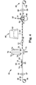
- FIG 4 is a schematic side view of an apparatus 50 and method for making a surface treating article 10 according to the present invention.
- the apparatus 50 includes an unwind assembly 52, a fastener loading station 60, a spin weld station 70, a machine vision and cutting station 80, a separation station 90, and a wind assembly 88.
- the surface treating web 30 is moved intermittently through the apparatus 50 as it progresses through each station. Preferably, the time a portion of the web 30 spends at each station is approximately equal to allow a smooth and even progression of the web 30 through apparatus 50.
- a length of surface treating web 30 is initially provided in unwinding assembly 52 on surface treating web roll 54 in roll form.
- roll 54 includes a brake.
- the brake is set to inhibit roll 54 from freely rotating, but instead to rotate with a slight amount of resistance.
- the web 30 progresses from roll 54 to an assembly formed by upper roll 56 and lower roll 57.
- the web 30 then progresses to the fastener loading station 60 of the apparatus 50.
- Platen 62 is located above the web 30.
- the fasteners 12 are loaded onto the platen 62 in predetermined locations to form two rows of fasteners 12.
- Platen 62 includes a vacuum (not shown) and vacuum holes 63, which hold the fasteners 12 in their predetermined locations while they are being transferred to the spin welders 74 in spin weld station 70.
- the relative locations of the fasteners 12 on the platen 62 are arranged to coordinate with the locations of the two rows of spin welders 74 in spin weld station 70.
- Platen 62 delivers the two rows of fasteners 12 to the spin weld station 70 of the apparatus. While the platen 62 delivers the fasteners 12 to the spin weld station 70, the web 30 advances forward to provide an area for the fasteners 12 to be spin welded and stops under the spin weld station 70.
- the fasteners 12 are lifted into chucks 76 on the bottom ends of the spin welders 74 and the platen 62 retreats back to its original position to receive more fasteners 12.
- Plate 75 is located below the web 30 opposite the spin welders 74. Plate 75 moves up vertically to support the web 30 just prior to when the spin welders 74 attach fasteners 12 to the web 30.
- the spin welders 74 spin weld the fasteners 12 onto the surface treating web 30.
- the web is stationary while the fasteners 12 are spin welded onto the web. Afterwards, plate 75 moves down vertically away from the web 30.
- the web advances forward to the machine vision and cutting station 80 of the apparatus 50.
- the web 30 comes to a stop to remain stationary under the machine vision and cutting station 80.
- the machine vision system 82 senses the position of the fasteners 12 on the web 30 that were spin welded onto the web at the previous station.
- the laser 84 partially cuts the web 30 around each of the fasteners 12 to form partially cut surface treating articles 10.
- the web 30 then starts again and proceeds from the machine vision and cutting station 80 to the separation station 90 of apparatus 50.
- the hollow cylinders 94 of the upper ram assembly 91 mechanically separate the partially cut surface treating articles 10 from the web 30.
- the separated surface treating articles 10 fall into the receiving bin 86.
- roll 102 includes a motor for winding the web around the roll.
- the surface treating web 30 is an abrasive web. More preferably, abrasive web may be either a coated abrasive web or a non woven abrasive web. Preferably, the web 30 is between 2 and 60 inches wide. More preferably, the web 30 is between 15 and 36 inches wide. However, the web width could vary depending on the number and size of fasteners 12 attached to the web 30 and the size of the finished surface treating article 10.
- portions of the web 30 move intermittently between the individual stations at approximately the same speed.
- the average speed of the web 30 is between 5 and 150 inches/minute through apparatus 50, and more preferably between 25 and 75 inches/minute through apparatus 50. The average speed is calculated taking into account the web acceleration from a stationary position at one station and web deceleration to a stationary position at an adjacent station.
- Figure 5 illustrates one preferred embodiment of apparatus 50.
- the unwind assembly 52 and wind assembly 88 are not illustrated.
- the apparatus 50 includes the fastener loading station 60, spin weld station 70, machine vision and cutting station 80, and separation station 90.
- Figures 6-13 illustrate each of these stations of the apparatus 50 in more detail.
- frame 51 extends between the fastener loading station 60 and the separation station 90.
- Upper web roll 56 and lower web roll 57 are mounted on one end of the frame 51.
- Upper web roll 68 and lower web roll 69 are mounted on the opposite end of the frame 51.
- Two upper belts 58 are wrapped around opposing ends of upper roll 56 and upper roll 68.
- Two lower belts 59 are wrapped around opposing ends of lower roll 57 and lower roll 69.
- Upper web rolls 56, lower web rolls 57, upper belts 58, and lower belts 59 form a web carrier for moving the web 30 through apparatus 50.
- the web carrier may include a drive shaft 68 driven by a motor, upper and lower rolls 56, 57, which are both idle, and upper and lower belts 58, 59.
- Drive shaft 68 may be connected to lower roll 69, and both drive shaft 68 and lower roll 69 will drive the belts 58, 59 to move the web 30 through the apparatus 50 in the direction of the arrow.
- spin welder stand 72 holds a plurality of spin welders 74 directly above the moving web 30.
- the stand 83 holds the machine vision system 82 and laser cutting system 84 directly above the moving web 30.
- stand 110 holds the separation apparatus 99.
- the separation apparatus 99 includes an upper ram assembly 91 and a web back up assembly 92.
- the upper ram assembly 91 is positioned above the moving web 30.
- the web back up assembly 92 is located below the moving web 30 opposite the upper ram assembly 91.
- FIG. 6 illustrates the fastener loading station 60 and the spin weld station 70 in more detail.
- the web 30 progresses through an assembly formed between the upper and lower roll 56, 57.
- the two upper belts 58 rotate about the ends of upper web roll 56.
- Two lower belts 59 rotate about the ends of lower web roll 57.
- the belts 58, 59 are rotated by upper and lower rolls 56, 57, the web 30 progresses through the apparatus 50.
- the fasteners 12 are loaded onto platen 62 in predetermined locations.
- a vacuum (not shown) holds the fasteners 12 in their respective locations.
- the fasteners are arranged relative to each other to coordinate with the location of the chucks 76 in the spin welders 74 located in stand 72.
- the fasteners are arranged in a first array 120 and a second array 122 (as shown in Figures 9 and 11). More preferably, each array 120, 122 is a row offasteners, with each row offset from the other. Each row is illustrated as having five fasteners. However, more or less fasteners may be used depending on the number of spin welders 74 in stand 72.
- stand 72 may hold up to a total of thirteen spin welders 74. More or less spin welders 74 may be used depending on the size of the finished surface treating articles 10 and the width of the web 30.
- the first row of spin welders 74 closest to the fastener loading station 60, may contain up to six spin welders. However, for clarity in the drawing, only two spin welders 74 are illustrated.
- the second row of spin welders 74 located opposite the first row, may contain up to seven spin welders 74. However, for clarity, only two of the seven spin welders 74 are shown. The second row of spin welders may be seen more clearly in Figure 9.
- Stand 72 includes a vertical stationary bar 78 located both in front and behind each spin welder 74. However, for clarity in the drawing, some of the bars 78 have been removed. As the spin welders 74 move vertically to spin weld a fastener 12 onto the web 30, the spin welder 74 slides up and down stationary bars 78. Horizontal support bars 79 support the ends of the stationary bars 78 within stand 72.
- FIG 7 is a schematic illustration of how the platen 62 loads the fasteners 12 into the spin welders 74.
- the chucks 76 of the spin welders 74 are illustrated in cross-section to show the grip arms 77 within the chucks 76.
- position A the fasteners 12 are loaded onto the platen 62 in their predetermined positions.
- the predetermined positions coordinate generally with the relative locations of the chucks 76 of the spin welders 74.
- the vacuum (not shown) is turned on to hold the fasteners 12 in their respective positions through vacuum holes 63.
- the platen then moves to position B, which is located directly below the spin welders 74.
- the fasteners 12 are now in position directly below the chucks 76 of the spin welders 74.
- the platen moves into position C, inserting the drive members 17 of fastener 12 directly into the grip arms 77 of the chuck 76.
- the vacuum is then turned off to release the fasteners 12.
- the grip arms 77 are preferably spring loaded to grasp the drive members 17 when the platen 62 moves back to position A to receive more fasteners 12.
- Mechanisms for moving the platen 62 as described herein are well known to those skilled in the art.
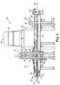
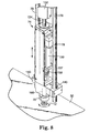
- FIG 8 illustrates one of the spin welders 74 in stand 72 (shown in Figure 6) spin welding a fastener 12 onto the web 30.
- the spin welder 74 includes a rotary motor 150 and vertical drive mechanism 152.
- Drive mechanism 152 is attached to support bar 79 (not shown).
- the drive mechanism 152 is an air cylinder.
- Two stationary bars 78 extend from the support bar 79 on either side of the spin welder 74.
- the motor 150 is mounted via a slidable frame 140 to the stationary bars 78 to allow the slidable frame 140 and motor 150 to be driven vertically by the rod 154 extending from the air cylinder 152. Extending from the motor 150 is a first shaft 157.
- the first shaft is coupled to a second shaft 160 by coupling 158.
- a chuck 76 mounted at the distal end of the second shaft 160 is a chuck 76 for holding the fastener 12. It is thus seen that the motor 150 spins first shaft 157, second shaft 160, and chuck 76; and that all of these components, along with the slidable frame 140, are raised and lowered together in response to actuating the drive mechanism 152.
- Chuck 76 can be any suitable fixture that will hold the fastener 12 during the spin weld operation. Chuck 76 must grip the fastener 12 securely enough to avoid slippage of the fastener 12 within the chuck 76 when the fastener is spun against the surface treating web 30. Chuck 76 should also provide for easy release of the fastener 12 after the spin weld process. Chuck 76 thus may include moveable elements for gripping and releasing the fastener 12, as is well known in the art.
- the forward travel of the web 30 stops below the spin welders 74 by upper and lower belts 58, 59.
- Plate 75 located below the web 30 raises up to support the web 30 opposite the spin welders 74. While the web 30 is held stationary below the spin welders 74, the spin welders 74 spin weld the fasteners 12 to the web 30. After the fasteners 12 are attached to the web 30, plate 75 lowers to allow the web 30 to move to the machine vision and cutting station.
- a preferred method of spin welding the fastener 12 to the surface treating web 30 is as follows.
- the spin weld method comprises the steps of holding stationary the surface treating web 30, mounting the fastener 12 in a chuck 76 to be driven by the spin welder 74, accelerating the chuck 76 and fastener 12 to the desired rotational speed, activating the drive mechanism 152 to move the planar surface 14 of the fastener 12 into contact with the surface treating web 30, applying sufficient force between the fastener 12 and surface treating web 30 while the fastener is spinning to achieve a frictional temperature required to soften the planar surface 14, allowing the chuck 76 and fastener 12 to stop rotation, maintaining force between the fastener 12 and surface treating web 30 while the planar surface 14 of the fastener 12 sufficiently cools to form a bond between the fastener 12 and surface treating article web 30, and releasing the fastener 12 from the chuck 76.
- the surface treating web 30 is mechanically held stationary between the upper and lower belts 58, 59 (not shown) to keep the web 30 stationary during the spin welding process.
- adhesive may be placed between the planar surface 14 of the fastener 12 and the surface treating web 30 prior to spin welding them together so as to form an adhesive bond between the fastener 12 and surface treating web 30.
- the following parameters are preferred when spin welding a nylon fastener 12 on a coated abrasive web with a backing comprising a resin-impregnated cloth or polymer-backed cloth.
- the parameters found to affect the strength of the melt-bond between the fastener 12 and surface treating web 30 are as follows.
- the force that the chuck 76 applies to the system is preferably between about 250 and 1100 lb., more preferably between about 300 and 700 lb., and most preferably between about 350 and 500 lb.
- the speed of the motor 150 is preferably between about 500 and 8000 RPM, more preferably, between 2000 and 6000 RPM, and most preferably, between about 2500 and 4500 RPM.
- the spin time is preferably between about 0.05 seconds and 0.6 seconds.
- the spin time is preferably between about 0.2 seconds and 0.45 seconds.
- the spin time is a measurement of how long the rotary motor 150 is maintained under power from the time the chuck 76 is positioned vertically within approximately 0.125 inches or less from the web 30 (essentially at the time of contact between the fastener 12 and the web 30) and ends with the command to remove power from the motor 150 after the fastener 12 contacts the surface treating web 30.
- the force between the fastener 12 on the web 30 must be maintained for a period of dwell time to form a sufficient bond between the fastener 12 and the web 30.
- the dwell time is between 0.1 and 1 seconds, and more preferably, between 0.2 and 0.5 seconds.
- Figure 9 illustrates the web 30 and fasteners 12 attached to web 30 as it exits the spin weld station 70 in the direction of the arrow to enter the machine vision and cutting station 80.
- the first row of spin welders 74 attach fasteners 12 arranged in a first array 120.
- the second row of spin welders 74 simultaneously attach fasteners 12 arranged in a second array 122.
- Each array 120, 122 contains a first fastener 124, a second fastener 126, a third fastener 128, a fourth fastener 130, and a fifth fastener 132.
- the fasteners in each array 120, 122 are spaced equally from each other.
- the spin welding stand 72 may hold up to thirteen spin welders, thus allowing thirteen fasteners to be simultaneously spin welded to the web.
- the web is illustrated as having only ten fasteners welded to it in the first and second arrays 120, 122.
- the first and second arrays 120, 122 are located some distance relative to one another and offset from one another so that other arrays of fasteners may be spin welded between them, as the web 30 progresses through the spin weld area 70.
- the arrays of fasteners 12 are arranged so as to optimize the number of surface treating articles formed from the web 30 and to reduce web waste.
- the fasteners 12 are spin welded in predetermined positions on the web. This is convenient for sensing the positions of the fasteners 12 and cutting around the fasteners 12 on the web 30 to make surface treating articles 10.
- the machine vision system 82 scans the web 30 to sense where the fasteners 12 are located on the web 30.
- the machine vision system 82 includes two cameras, which take digital images of the web 30 in two different locations. More preferably, the first camera takes a digital image of the first array 120 of fasteners 12 located on the web 30 and the second camera takes a digital image of the second array 122 of fasteners 12 located on the web 30. Most preferably, the first camera takes a digital image of the first fastener 124 in the first array 120 and the second camera takes a digital image of the fifth fastener 132 in the second array 122.
- the cameras send the output to the machine vision system computer processor, which processes the images to determine the location of the fasteners 12.
- the computer processor determines the coordinates of the first fastener 124 in first array 120 and the fifth fastener 132 in the second array 122. These coordinates are then sent to the laser system, which directs where the laser 84 is to cut. Laser 84 then cuts the web around the each of the fasteners to form surface treating articles 10, as illustrated in Figure 11.
- the computer processor may determine the coordinates of the centers of the fastener 12 to allow laser 84 to cut around the centers of the fasteners 12 to form surface treating articles with fasteners 12 centered thereon.
- Figure 10 is a digitally recorded image showing the view of a fastener on the surface treating web using the camera in the machine vision system 82.
- the fiducial 18 located on the distal end of the drive member is used to sense the position of the fastener on the web 30.
- the machine vision system searches for the pattern the fiducial 18 on the fastener 12 creates.
- the machine vision system camera includes a ring light, which shines directly onto the web 30 and fastener 12 from around the camera.
- the camera in the machine vision system records the digital image illustrated in Figure 10.
- the camera image is preferably in a gray scale image.
- the areas of the fastener that are perpendicular to the direction of the light will reflect the light back, producing white areas.
- the fiducial 18 includes a first reflective surface 20 and non-reflective surface 24.
- the term “reflective” refers to the surface reflecting light back to the camera.
- the term “non-reflective” refers to the surface reflecting light away from the camera.
- the first reflective surface 20 is preferably perpendicular to the direction of the light and preferably parallel to the web direction.
- the non-reflective surface 24 is preferably at some angle other than perpendicular to the direction of the light and not parallel to the web direction.
- the non-reflective surface 24 is at angle ⁇ between 20° and 70° measured relative to the first reflective surface 20.
- ⁇ is between 40° and 50°. Most preferably, ⁇ is 45°.
- the distal end surface 19 of the distal end of the drive member 17 includes the second reflective surface 22, which is preferably perpendicular to the direction of the light and parallel to the web direction.
- the first and second reflective surfaces 20, 22 reflect light to the camera, producing white areas, and the non-reflective surface 24 does not reflect light to the camera, producing a black area. Since the non-reflective surface 24 is located between the first and second reflective surfaces 20, 22, this creates a clear image for which the machine vision 82 system scans.
- the first reflective surface 20 is in the shape of a circle and reflects back a white circle.
- the non-reflective surface 24 is in the shape of an annulus surrounding the first reflective surface 20 and causes a black annulus centered around the white circle.
- the second reflective surface 22 is in the shape of an annulus surrounding the non-reflective surface 24 and reflects back a white annulus centered around the black annulus.
- the position of the fastener 12 is sent to the laser control system. Then, the laser is directed to cut around the fastener to form a surface treating article 10.
- machine vision system computer may determine the position of the center of the fastener using the same image. Once the position of the position of the center of the fastener 12 is determined, the output is sent to the laser control system. Then, the laser is directed to cut around the center of the fastener to form a surface treating article with the fastener 12 centered thereon.
- Any commercially available machine vision system 82 capable of obtaining the conditions described herein may be used, such as the AcuityTM VP-2000 available from RVSI Acuity, Inc. located in Nashua, New Hampshire.
- Another suitable machine vision system 82 includes DVT Series 600 available from DVT, Inc. located in Norcross, Georgia.
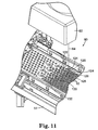
- Figure 11 illustrates the machine vision and cutting station 80 of the apparatus 50.
- the web 30 advances until the arrays 120, 122 of fasteners 12 that were simultaneously attached by spin welders 74 on the web 30 are underneath the machine vision and cutting system.
- the web stops and is held stationary while the locations of the fasteners 12 on the web are sensed and while the laser 84 cuts the web 30 around the fasteners.
- the laser 84 cuts around the fasteners 12 located on the web 30 to form surface treating articles 10.
- the laser 84 is illustrated as starting to cut around the first fastener 124 of the first array of fasteners 120. The laser will then continue to cut around the second fastener 126 and proceed to the third, fourth and fifth fasteners 128-132 in the first array 120 before proceeding to cut around the fasteners 124-132 in the second array 122.
- Each fastener 12 may be sensed individually as mentioned above prior to cutting around each fastener 12. However, it is also possible to sense only one or some of the fasteners 12 within an array of fasteners and then to determine location of all of the fasteners 12 in the array prior to cutting around each fastener within the array. For instance, if an array of fasteners included only a first fastener and a second fastener and it is known that the first fastener and second fastener are located a certain distance and direction from one another on the web 30, then once the position of the first fastener has been sensed, the position of the second fastener may be determined from the relative positions of the first fastener and the second fastener.
- the fasteners 12 in each array 120, 122 were simultaneously spin welded to the web 30 by spin welders 74. Therefore, the positions of the fasteners in the arrays 120, 122 coordinate with the relative positions of the chucks 76 in the spin welders 74 in stand 72. Preferably, the chucks 76 are spaced equally so that the fasteners are spaced equally from each other in one direction.
- the position of each of the fasteners 12 in the first and second arrays 120, 122 may be determined by: 1) sensing the location of the first fastener 124 in the first array 120 on the web 30; 2) sensing the location of the fifth fastener 132 in the second array 122 on the web 30; and 3) calculating the position of each of the fasteners 12 in the arrays 120, 122 based on the known factors. Once the position of each of the fasteners 12 within the arrays 120, 122 have been determined, the laser 84 will cut around the fasteners to form surface treating articles 10.
- the laser may cut that pattern after it receives the sensed locations of the first fastener 124 in the first array 120 and the fifth fastener 132 in the second array 122 on the web 130, without calculating the position of each of the fasteners 12 in the arrays 120, 122.
- the fiducial 18 is centered relative to the drive member 17.
- the benefit of having the fiducial 18 centered relative to the drive member 17 is that the laser 84 may cut a nearly perfectly centered surface treating article with the fastener 12 centered thereon. This allows for final surface treating article which will wear more evenly over time in comparison to a surface treating article having a fastener that is not centered.
- the laser partially cuts the web 30 around the fasteners 12 to form a partially cut surface treating article 10.
- the laser 84 cuts partially through the thickness of the web 30 so that the surface treating article 10 stays with the web until it is received at the separation station 90.
- the laser preferably cuts through the backing on the back surface, but not the abrasive coating on the working surface of the web.
- the laser 84 may cut all the way through the web 30 to separate the surface treating articles 10 from the web completely, and thus, eliminating the need for the separation station 90.
- a suitable laser system includes a laser generator coupled to required services, a beam delivery system, and a work surface containing or attached to an exhaust system.
- the beam delivery system of laser 84 includes the following parameters: a galvanometer-based or other scanning optical-based system, minimum of 50 mm aperture, a focused beam size of less than 300x10 -6 m in diameter, minimum field size of 15 inches, power capability of 2500 watts, speed of mirrors to direct the beam at a speed of between 300 and 2000 mm/sec (measured on the working surface) and acceleration greater than 200 g (measured on the working surface).
- the beam delivery system is a completely reflective optical system, as opposed to a transmissive optical system.
- the suitable laser system includes a total system accuracy of better than plus or minus 0.004 inches in any field position and for the lifetime of the equipment.
- Any commercially available lasers 84 capable of obtaining the conditions described herein may be used, such as the LPM-2500 and LPM-1000 available from LasX Industries, Inc. located in White Bear Lake, MN.
- the separation apparatus 99 is mounted to stand 110.
- the separation apparatus 99 includes an upper ram assembly 91.
- the upper ram assembly which is positioned above the moving web 30, moves vertically to mechanically remove the partially cut surface treating articles 10 for the web 30. After the surface treating articles 10 are mechanically removed from the web, they fall into bin 86 (not illustrated).
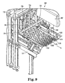
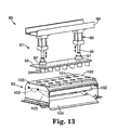
- FIG 13 illustrates an exploded view of the separation apparatus 99, which is convenient for discussing the different components of the separation apparatus 99.
- the separation apparatus 99 includes an upper ram assembly 91 and a web back-up assembly 92.
- the upper ram assembly 91 includes a stationary bracket 98, which is mounted to stand 110 (see Figure 12), and ram plate 93.
- Drive mechanism 95 is supported by stationary bracket 98.
- the drive mechanism 95 is an air cylinder.
- Shafts 96 extend from the drive mechanisms 95.
- Flange couplings 97 attach the shafts 96 to the ram plate 93.
- the drive mechanism 95 and shafts 96 move the ram plate 93 vertically. Extending from the bottom of the ram plate 93 opposite the couplings 97 are cylinders 94.
- the arrangement of cylinder 94 on ram plate 93 corresponds to the arrays of partially cut surface treating articles 120, 122.
- the cylinders 94 are hollow and sized to match the perimeter of the partially cut surface treating articles 10.
- the upper ram assembly 91 is illustrated in the extended position, as if to mechanically separate the partially cut surface treating articles 10 out of the web. In this position, cylinders 94 extend through the web 30 and into holes 101 in plate 100. However, in this exploded view the upper ram assembly 91 and back up assembly 92 have been separated for illustrative purposes.
- Web back-up assembly 92 is located below the upper ram assembly 91 and below the moving web 30.
- Web back-up assembly 92 includes plate 100 having a plurality of holes 101 sized to receive the cylinders 94 of the upper ram assembly 91.
- Web back-up assembly 92 includes a frame 105, which supports plate 100. Mounted inside frame 105 just below plate 100 are two back up plates 102. The two back up plates pivot about pivots 103. Two transfer chutes 104 are mounted below the two back up plates 102 inside frame 105. The transfer chutes 104 are fixed within the frame 105 and do not move.
- the back up plates 102 are pivoted up to contact the cylinders 94 as they move through holes 101 in plate 100. After the partially cut surface treating articles 10 are mechanically separated from the web 30, they fall onto the plate 102. Next, the back up plates 102 pivot about pivots 103 into the down position, as illustrated in Figure 13. The surface treating articles 10 then slide down onto the transfer chutes 104 and are directed into bin 86 (See Figure 4.)
- Wind assembly 88 includes the surface treating web roll 89.
- the remaining web 30 is wound around surface treating web roll 89.
- stations 52, 60, 70, 80, 90, and 88 of apparatus 50 are coordinated such that the web 30 stops and each station does its step simultaneously at different portions of the web.
- stations 52, 60, 70, 80, 90, and 88 may be each independent or could be combined in a variety of sequences.
- the cutting means illustrated for apparatus 50 is a laser, other cutting means may be used instead.
- suitable cutting means includes die cutting, water jet cutting, or ultrasonic cutting.
- the fasteners 12 may be attached to the web 30 by methods other than spin welding.
- machine vision in combination with the laser to perform the inventive method
- other combinations are within the invention, such as combining machine vision with the other suitable cutting means mentioned above or combining other sensing means with laser cutting.
Abstract
Description
Claims (26)
- A method of making a surface treating article, comprising the steps of:a) providing a surface treating web with a fastener attached thereto;b) sensing a position coordinate in each of two dimensions of the fastener on the surface treating web; andc) cutting the surface treating web around the fastener to provide a surface treating article including the fastener.
- The method of claim 1, wherein step b) further comprises sensing the position of the center of the fastener and step c) comprises cutting the surface treating web around the center of the fastener to provide a surface treating article including the fastener centered thereon.
- The method of claim 1, wherein step b) is performed using machine vision.
- The method of claim 3, wherein the fastener includes a fiducial, and wherein step b) further comprises using the machine vision to determine the position of the fiducial to thereby determine the position of the fastener on the surface treating web.
- The method of claim 1, wherein step c) further comprises laser cutting the surface treating web around the fastener to provide a surface treating article with the fastener thereon.
- The method of claim 1, further comprising:d) advancing the web forward to bring a second fastener attached to the surface treating web to within a desired region; ande) repeating steps b) and c) with regard to said second fastener to provide a second surface treating article.
- The method of claim 6, wherein the method is a continuous method in which a plurality of fasteners are sequentially brought into said desired region, and steps b) and c) are then repeated with respect to each of the plurality of said fasteners.
- The method of claim 1, wherein step c) further comprises partially cutting the surface treating web around the fastener to provide a partially-cut surface treating article with the fastener thereon, and subsequently separating the surface treating article from the surface treating web.
- The method of claim 1, further comprising the step of attaching the fastener to the surface treating web prior to step a).
- The method of claim 9, wherein the step of attaching the fastener to the surface treating web comprises a spin welding.
- The method of claim 10, wherein the step of attaching the fastener to the surface treating web comprises placing a thermoplastic layer of adhesive between the fastener and the surface treating web prior to spin welding.
- The method of claim 1, wherein:step a) includes providing a surface treating web with a plurality of fasteners fastened thereto;step b) includes sensing the position of at least one of the plurality of fasteners on the surface treating web; andstep c) includes cutting the surface treating web around each of the plurality of fasteners to provide a plurality of surface treating articles, each including one of the plurality of fasteners.
- The method of claim 12, wherein each of the plurality of fasteners is located in a predetermined position forming an array of fasteners.
- The method of claim 12 or 13, wherein the plurality of fasteners includes a first fastener and a second fastener, wherein step b) includes sensing the position of the first fastener and wherein the position of the second fastener is determined from the relative positions of the first fastener and the second fastener.
- The method of claim 14, wherein step b) further comprises sensing the position of the first fastener with machine vision.
- The method of any of claims 12 to 14, wherein step b) further comprises determining the position of the center of at least one of the plurality of fasteners and step c) comprise cutting the surface treating web around the centers of the plurality of fasteners to provide a plurality of surface treating articles each including one of the plurality of fasteners centered thereon.
- The method of claim 15, wherein at least one of the plurality of fasteners includes a fiducial to be sensed by the machine vision.
- The method of claim 12, wherein step c) further comprises laser cutting the surface treating web around the plurality of fasteners to provide a plurality of surface treating articles each including one of the fasteners thereon.
- The method of claim 12, wherein step c) further comprises partially cutting the surface treating web around the plurality of fasteners to provide a plurality of partially-cut surface treating articles each including one of the fasteners thereon and subsequently removing the plurality of surface treating articles from the surface treating web.
- The method of claim 12, further comprising the step of attaching the plurality of fasteners to the surface treating web in a predetermined array prior to step a).
- The method of claim 20, wherein the step of attaching the plurality of fasteners to the surface treating web in a predetermined array comprises spin welding.
- A surface treating article, comprising:wherein said fiducial includes a planar first reflective surface, a non-reflective surface, and a planar second reflective surface, wherein the second reflective surface occupies a different plane than the first reflective surface, anda) a surface treating member; andb) a fastener on said surface treating member including a drive member, wherein said drive member includes a distal end, wherein said distal end includes a fiducial,
wherein said non-reflective surface is at an angle relative to said first reflective surface and said second reflective surface. - The surface treating article of claim 22, wherein said first reflective surface and said second reflective surface are parallel.
- The surface treating article of claim 22, wherein the surface treating member comprises an abrasive member, and wherein said abrasive member includes a working surface and a back surface opposite the working surface.
- An apparatus for making a plurality of surface treating articles comprising:a) a spinwelder for attaching a plurality of fasteners to a surface treating web, wherein each of the plurality of fasteners is located in a predetermined position forming an array of fasteners, and wherein the plurality of fasteners includes a first fastener and a second fastener;b) a machine vision system to sense a position of the first fastener on the surface treating web and determine a position of the second fastener relative to the position of the first fastener andc) a laser to cut the surface treating web around each fastener to provide a surface treating article with a fastener thereon.
- The apparatus for making a plurality of surface treating articles of claim 25, further including:d) a web carrier for advancing the surface treating web.
Applications Claiming Priority (3)
| Application Number | Priority Date | Filing Date | Title |
|---|---|---|---|
| US09/607,210 US6609951B1 (en) | 2000-06-30 | 2000-06-30 | Method of making a surface treating article |
| US607210 | 2000-06-30 | ||
| PCT/US2000/032375 WO2002002278A1 (en) | 2000-06-30 | 2000-11-28 | Method of making a surface treating article and such a surface treating article |
Publications (2)
| Publication Number | Publication Date |
|---|---|
| EP1296803A1 EP1296803A1 (en) | 2003-04-02 |
| EP1296803B1 true EP1296803B1 (en) | 2005-08-10 |
Family
ID=24431284
Family Applications (1)
| Application Number | Title | Priority Date | Filing Date |
|---|---|---|---|
| EP00983771A Expired - Lifetime EP1296803B1 (en) | 2000-06-30 | 2000-11-28 | Method of making a surface treating article and such a surface treating article |
Country Status (7)
| Country | Link |
|---|---|
| US (3) | US6609951B1 (en) |
| EP (1) | EP1296803B1 (en) |
| JP (1) | JP4831919B2 (en) |
| AT (1) | ATE301531T1 (en) |
| AU (1) | AU2001220483A1 (en) |
| DE (1) | DE60021921T2 (en) |
| WO (1) | WO2002002278A1 (en) |
Families Citing this family (14)
| Publication number | Priority date | Publication date | Assignee | Title |
|---|---|---|---|---|
| US7121924B2 (en) * | 2004-04-20 | 2006-10-17 | 3M Innovative Properties Company | Abrasive articles, and methods of making and using the same |
| EP1991393B1 (en) * | 2006-02-28 | 2014-03-26 | 3M Innovative Properties Company | Abrasive article and its use |
| BR112012004334B1 (en) * | 2009-08-28 | 2020-10-27 | 3M Innovative Properties Company | abrasive article and method for preparing the same |
| CN102072735B (en) * | 2009-11-24 | 2012-11-14 | 深圳市赛格导航科技股份有限公司 | Method and system for calculating mileage quickly |
| US20150273658A1 (en) * | 2012-09-27 | 2015-10-01 | Saint-Gobain Abrasives, Inc. | Button for a attaching an abrasive article to a back-up pad |
| US20140263220A1 (en) * | 2013-03-15 | 2014-09-18 | Abbott Cardiovascular Systems Inc. | Laser cutting process monitoring and control |
| BR112016014805B1 (en) * | 2013-12-27 | 2021-03-09 | Saint-Gobain Abrasifs | non-woven abrasive articles made by friction welding |
| US11607776B2 (en) | 2016-07-20 | 2023-03-21 | 3M Innovative Properties Company | Shaped vitrified abrasive agglomerate, abrasive articles, and method of abrading |
| CN109890931B (en) | 2016-10-25 | 2021-03-16 | 3M创新有限公司 | Magnetizable abrasive particles and abrasive articles comprising magnetizable abrasive particles |
| EP3532562B1 (en) | 2016-10-25 | 2021-05-19 | 3M Innovative Properties Company | Magnetizable abrasive particle and method of making the same |
| EP3533075A4 (en) | 2016-10-25 | 2020-07-01 | 3M Innovative Properties Company | Method of making magnetizable abrasive particles |
| EP3532249A4 (en) | 2016-10-25 | 2020-06-17 | 3M Innovative Properties Company | Structured abrasive articles and methods of making the same |
| CN109890564B (en) | 2016-10-25 | 2022-04-29 | 3M创新有限公司 | Shaped vitrified abrasive agglomerates with shaped abrasive particles, abrasive articles, and related methods |
| CA3054036A1 (en) * | 2018-12-28 | 2020-06-28 | Virtual Machines Inc. | Method and system for producing abrasive products |
Family Cites Families (51)
| Publication number | Priority date | Publication date | Assignee | Title |
|---|---|---|---|---|
| US3307300A (en) * | 1964-10-01 | 1967-03-07 | Field Albert | Abrasive disk unit |
| GB1126136A (en) | 1966-06-20 | 1968-09-05 | American Velcro Inc | Improvements in abrasive pad holding device |
| US3561938A (en) | 1968-02-05 | 1971-02-09 | Merit Products Inc | Abrasive disk |
| US3667170A (en) * | 1969-03-11 | 1972-06-06 | Norton Co | Finishing article and support member therefor |
| US3562968A (en) | 1969-03-12 | 1971-02-16 | Minnesota Mining & Mfg | Surface treating tool |
| US3668453A (en) * | 1970-07-01 | 1972-06-06 | Hughes Aircraft Co | Electrical switch device having a fed liquid-metal cathode and a non-intercepting anode |
| US3738569A (en) * | 1970-11-30 | 1973-06-12 | J Killaly | Punch press |
| US3688453A (en) | 1970-12-11 | 1972-09-05 | Minnesota Mining & Mfg | Abrasive articles |
| US3800483A (en) * | 1971-01-22 | 1974-04-02 | W Sherman | Method of making grinding wheel mounts |
| US3851357A (en) | 1971-02-03 | 1974-12-03 | American Velcro Inc | Fastener |
| IT948983B (en) * | 1971-02-03 | 1973-06-11 | American Velcro Inc | FIXING DEVICE AND PROCEDURE FOR ITS MANUFACTURING |
| US3747286A (en) * | 1971-07-14 | 1973-07-24 | Standard Abrasives | Abrasive finishing article assembly |
| US4227350A (en) * | 1977-11-02 | 1980-10-14 | Minnesota Mining And Manufacturing Company | Low-density abrasive product and method of making the same |
| IT1145270B (en) | 1979-07-09 | 1986-11-05 | Merit Abrasive Prod | IMPROVEMENT IN ABRASIVE DISCS |
| US4551189A (en) | 1984-12-12 | 1985-11-05 | Illinois Tool Works Inc. | Friction welded fastener system |
| US4939439A (en) | 1985-09-26 | 1990-07-03 | Unisearch Limited | Robot vision and optical location systems |
| US4774788A (en) * | 1986-05-06 | 1988-10-04 | Camel Grinding Wheel Works, Sarid Ltd. | Grinding wheel with a single-piece hub |
| US4907169A (en) | 1987-09-30 | 1990-03-06 | International Technical Associates | Adaptive tracking vision and guidance system |
| US4918611A (en) | 1988-07-21 | 1990-04-17 | Industrial Technology Research Institute | Method and apparatus for controlling laser cutting by image processing |
| US4961149A (en) | 1989-01-27 | 1990-10-02 | Intellitek, Inc. | Method and apparatus for marking and cutting a flexible web |
| US4978830A (en) | 1989-02-27 | 1990-12-18 | National Semiconductor Corporation | Laser trimming system for semiconductor integrated circuit chip packages |
| US4998005A (en) | 1989-05-15 | 1991-03-05 | General Electric Company | Machine vision system |
| US4995087A (en) | 1989-05-15 | 1991-02-19 | General Electric Company | Machine vision system |
| CA1312274C (en) * | 1989-08-08 | 1993-01-05 | Converdis Inc. | High speed perforation machine for perforating predetermined repetitive patterns in a continuous moving web |
| WO1991004828A1 (en) | 1989-09-27 | 1991-04-18 | Australian Electro Optics Pty. Ltd. | High power, multi axis laser beam cutter with image processing monitor |
| US5193120A (en) | 1991-02-27 | 1993-03-09 | Mechanical Technology Incorporated | Machine vision three dimensional profiling system |
| JPH05250021A (en) * | 1991-02-28 | 1993-09-28 | Ando Electric Co Ltd | Tool exchange device |
| US5380978A (en) | 1991-07-12 | 1995-01-10 | Pryor; Timothy R. | Method and apparatus for assembly of car bodies and other 3-dimensional objects |
| JP3103904B2 (en) * | 1991-11-01 | 2000-10-30 | 九州日立マクセル株式会社 | Screen printing metal mask and method of manufacturing the same |
| US5316812A (en) | 1991-12-20 | 1994-05-31 | Minnesota Mining And Manufacturing Company | Coated abrasive backing |
| JP3242108B2 (en) * | 1992-01-30 | 2001-12-25 | 富士通株式会社 | Target mark recognition and tracking system and method |
| AU4786393A (en) | 1992-07-28 | 1994-02-14 | Tulon Co. | Method and apparatus for tool management |
| GB9216643D0 (en) | 1992-08-05 | 1992-09-16 | Univ Loughborough | Automatic operations on materials |
| US5381228A (en) * | 1993-09-30 | 1995-01-10 | Hoover Universal, Inc. | Rapid estimation of the oxygen permeation rate of a thin film on a plastic container |
| US5607345A (en) * | 1994-01-13 | 1997-03-04 | Minnesota Mining And Manufacturing Company | Abrading apparatus |
| US5505747A (en) * | 1994-01-13 | 1996-04-09 | Minnesota Mining And Manufacturing Company | Method of making an abrasive article |
| US5611949A (en) * | 1994-05-04 | 1997-03-18 | Norfin International, Inc. | Method and apparatus for laser cutting separate items carried on a continuously moving web |
| US5775984A (en) * | 1994-09-23 | 1998-07-07 | Olson; Jim C. | Removable-resuable fibrous scrubbing pad for use in wet power orbital scuffing applications |
| JPH08333086A (en) * | 1995-06-09 | 1996-12-17 | Komatsu Ltd | Processor of photographed picture image of hung cargo |
| US5951389A (en) * | 1995-10-23 | 1999-09-14 | Weiler Corporation | Drive system for small diameter abrasive discs |
| JP2000501999A (en) * | 1995-12-18 | 2000-02-22 | ワシュー パトリック | Paper cutter for variable format |
| US6005978A (en) | 1996-02-07 | 1999-12-21 | Cognex Corporation | Robust search for image features across image sequences exhibiting non-uniform changes in brightness |
| US5777880A (en) | 1996-02-21 | 1998-07-07 | Albani Bayeux, Inc. | Method and apparatus for correctively guiding a cutting device on a predetermined path along a sheet material |
| US5766277A (en) | 1996-09-20 | 1998-06-16 | Minnesota Mining And Manufacturing Company | Coated abrasive article and method of making same |
| US6064759A (en) | 1996-11-08 | 2000-05-16 | Buckley; B. Shawn | Computer aided inspection machine |
| US5807449A (en) * | 1997-01-08 | 1998-09-15 | Hooker; Jeffrey A. | Workpiece treating apparatus and method of treating same |
| US5931729A (en) | 1997-04-15 | 1999-08-03 | Minnesota Mining And Manufacturing Company | Article made by spin welding a fastener thereto |
| US5978521A (en) | 1997-09-25 | 1999-11-02 | Cognex Corporation | Machine vision methods using feedback to determine calibration locations of multiple cameras that image a common object |
| GB9803604D0 (en) | 1998-02-21 | 1998-04-15 | Merit Abrasives Europ Limited | Surface treatment |
| US20050135912A1 (en) * | 1999-07-23 | 2005-06-23 | Hagen Schempf | Robotic systems for handling objects |
| US6432796B1 (en) * | 2000-06-28 | 2002-08-13 | Micron Technology, Inc. | Method and apparatus for marking microelectronic dies and microelectronic devices |
-
2000
- 2000-06-30 US US09/607,210 patent/US6609951B1/en not_active Expired - Lifetime
- 2000-11-28 DE DE60021921T patent/DE60021921T2/en not_active Expired - Lifetime
- 2000-11-28 WO PCT/US2000/032375 patent/WO2002002278A1/en active IP Right Grant
- 2000-11-28 AU AU2001220483A patent/AU2001220483A1/en not_active Abandoned
- 2000-11-28 JP JP2002506894A patent/JP4831919B2/en not_active Expired - Fee Related
- 2000-11-28 EP EP00983771A patent/EP1296803B1/en not_active Expired - Lifetime
- 2000-11-28 AT AT00983771T patent/ATE301531T1/en not_active IP Right Cessation
-
2003
- 2003-06-17 US US10/462,479 patent/US6817935B2/en not_active Expired - Lifetime
-
2004
- 2004-09-08 US US10/936,419 patent/US7182682B2/en not_active Expired - Fee Related
Also Published As
| Publication number | Publication date |
|---|---|
| JP2004501788A (en) | 2004-01-22 |
| DE60021921D1 (en) | 2005-09-15 |
| US6817935B2 (en) | 2004-11-16 |
| JP4831919B2 (en) | 2011-12-07 |
| AU2001220483A1 (en) | 2002-01-14 |
| US20050064056A1 (en) | 2005-03-24 |
| WO2002002278A8 (en) | 2002-02-07 |
| US6609951B1 (en) | 2003-08-26 |
| DE60021921T2 (en) | 2006-05-18 |
| US7182682B2 (en) | 2007-02-27 |
| ATE301531T1 (en) | 2005-08-15 |
| US20030207652A1 (en) | 2003-11-06 |
| WO2002002278A1 (en) | 2002-01-10 |
| EP1296803A1 (en) | 2003-04-02 |
Similar Documents
| Publication | Publication Date | Title |
|---|---|---|
| EP1296803B1 (en) | Method of making a surface treating article and such a surface treating article | |
| US5397415A (en) | Method for manufacturing laminated prepreg members | |
| US6974930B2 (en) | Laser scanner | |
| TWI413560B (en) | Method of and apparatus for joining metal strips | |
| JP2003508905A (en) | Unsupported polishing belt for chemical mechanical polishing | |
| KR101948939B1 (en) | Method and apparatus for centering of spin finishing of lens | |
| EP1276594A1 (en) | Method for attaching a fastener to a surface treating member, and such an article having a fastener | |
| CN203804722U (en) | Lens processing device | |
| JPH07110498B2 (en) | Method and apparatus for cutting prepreg tape | |
| CA1309605C (en) | Method of producing grinding tool and apparatus for producing same | |
| US20040055691A1 (en) | Method and apparatus for making a laminate | |
| JP2532446B2 (en) | Electrostatographic imaging belt manufacturing apparatus and method | |
| EP0937544A2 (en) | Surface treatment | |
| JP2788542B2 (en) | Mandrel polishing equipment | |
| EP1098736B1 (en) | A spliced abrasive web and method for the same | |
| JPH053739A (en) | Method and device for grinding surface of fishing rod | |
| JP3714826B2 (en) | Rubber flash removing device and rubber flash removing method for metal rubber composite product | |
| JPH0528766Y2 (en) | ||
| CA1323209C (en) | High lamination speed automatic laminator | |
| JPH078542B2 (en) | Finishing method and apparatus for FRP bonded parts | |
| KR910008673Y1 (en) | Automatic line up apparatus for condenser | |
| CA2307794A1 (en) | Plate tool having quick-engaging element, provided with work surface | |
| JP3974052B2 (en) | Processing method of transmission belt | |
| JP2782434B2 (en) | A method of sticking paper to plywood and a laminator for it | |
| JPH046119A (en) | Method for forming lens |
Legal Events
| Date | Code | Title | Description |
|---|---|---|---|
| PUAI | Public reference made under article 153(3) epc to a published international application that has entered the european phase |
Free format text: ORIGINAL CODE: 0009012 |
|
| 17P | Request for examination filed |
Effective date: 20030123 |
|
| AK | Designated contracting states |
Kind code of ref document: A1 Designated state(s): AT BE CH CY DE DK ES FI FR GB GR IE IT LI LU MC NL PT SE TR |
|
| AX | Request for extension of the european patent |
Extension state: AL LT LV MK RO SI |
|
| 17Q | First examination report despatched |
Effective date: 20040220 |
|
| GRAP | Despatch of communication of intention to grant a patent |
Free format text: ORIGINAL CODE: EPIDOSNIGR1 |
|
| GRAS | Grant fee paid |
Free format text: ORIGINAL CODE: EPIDOSNIGR3 |
|
| GRAA | (expected) grant |
Free format text: ORIGINAL CODE: 0009210 |
|
| AK | Designated contracting states |
Kind code of ref document: B1 Designated state(s): AT BE CH CY DE DK ES FI FR GB GR IE IT LI LU MC NL PT SE TR |
|
| PG25 | Lapsed in a contracting state [announced via postgrant information from national office to epo] |
Ref country code: IT Free format text: LAPSE BECAUSE OF FAILURE TO SUBMIT A TRANSLATION OF THE DESCRIPTION OR TO PAY THE FEE WITHIN THE PRESCRIBED TIME-LIMIT;WARNING: LAPSES OF ITALIAN PATENTS WITH EFFECTIVE DATE BEFORE 2007 MAY HAVE OCCURRED AT ANY TIME BEFORE 2007. THE CORRECT EFFECTIVE DATE MAY BE DIFFERENT FROM THE ONE RECORDED. Effective date: 20050810 Ref country code: FI Free format text: LAPSE BECAUSE OF FAILURE TO SUBMIT A TRANSLATION OF THE DESCRIPTION OR TO PAY THE FEE WITHIN THE PRESCRIBED TIME-LIMIT Effective date: 20050810 Ref country code: BE Free format text: LAPSE BECAUSE OF FAILURE TO SUBMIT A TRANSLATION OF THE DESCRIPTION OR TO PAY THE FEE WITHIN THE PRESCRIBED TIME-LIMIT Effective date: 20050810 Ref country code: NL Free format text: LAPSE BECAUSE OF FAILURE TO SUBMIT A TRANSLATION OF THE DESCRIPTION OR TO PAY THE FEE WITHIN THE PRESCRIBED TIME-LIMIT Effective date: 20050810 Ref country code: CH Free format text: LAPSE BECAUSE OF FAILURE TO SUBMIT A TRANSLATION OF THE DESCRIPTION OR TO PAY THE FEE WITHIN THE PRESCRIBED TIME-LIMIT Effective date: 20050810 Ref country code: AT Free format text: LAPSE BECAUSE OF FAILURE TO SUBMIT A TRANSLATION OF THE DESCRIPTION OR TO PAY THE FEE WITHIN THE PRESCRIBED TIME-LIMIT Effective date: 20050810 Ref country code: LI Free format text: LAPSE BECAUSE OF FAILURE TO SUBMIT A TRANSLATION OF THE DESCRIPTION OR TO PAY THE FEE WITHIN THE PRESCRIBED TIME-LIMIT Effective date: 20050810 Ref country code: ES Free format text: LAPSE BECAUSE OF FAILURE TO SUBMIT A TRANSLATION OF THE DESCRIPTION OR TO PAY THE FEE WITHIN THE PRESCRIBED TIME-LIMIT Effective date: 20050810 Ref country code: TR Free format text: LAPSE BECAUSE OF FAILURE TO SUBMIT A TRANSLATION OF THE DESCRIPTION OR TO PAY THE FEE WITHIN THE PRESCRIBED TIME-LIMIT Effective date: 20050810 |
|
| REG | Reference to a national code |
Ref country code: GB Ref legal event code: FG4D |
|
| REG | Reference to a national code |
Ref country code: CH Ref legal event code: EP |
|
| REG | Reference to a national code |
Ref country code: IE Ref legal event code: FG4D |
|
| REF | Corresponds to: |
Ref document number: 60021921 Country of ref document: DE Date of ref document: 20050915 Kind code of ref document: P |
|
| PG25 | Lapsed in a contracting state [announced via postgrant information from national office to epo] |
Ref country code: SE Free format text: LAPSE BECAUSE OF FAILURE TO SUBMIT A TRANSLATION OF THE DESCRIPTION OR TO PAY THE FEE WITHIN THE PRESCRIBED TIME-LIMIT Effective date: 20051110 Ref country code: DK Free format text: LAPSE BECAUSE OF FAILURE TO SUBMIT A TRANSLATION OF THE DESCRIPTION OR TO PAY THE FEE WITHIN THE PRESCRIBED TIME-LIMIT Effective date: 20051110 Ref country code: GR Free format text: LAPSE BECAUSE OF FAILURE TO SUBMIT A TRANSLATION OF THE DESCRIPTION OR TO PAY THE FEE WITHIN THE PRESCRIBED TIME-LIMIT Effective date: 20051110 |
|
| PG25 | Lapsed in a contracting state [announced via postgrant information from national office to epo] |
Ref country code: CY Free format text: LAPSE BECAUSE OF FAILURE TO SUBMIT A TRANSLATION OF THE DESCRIPTION OR TO PAY THE FEE WITHIN THE PRESCRIBED TIME-LIMIT Effective date: 20051128 Ref country code: IE Free format text: LAPSE BECAUSE OF NON-PAYMENT OF DUE FEES Effective date: 20051128 |
|
| PG25 | Lapsed in a contracting state [announced via postgrant information from national office to epo] |
Ref country code: MC Free format text: LAPSE BECAUSE OF NON-PAYMENT OF DUE FEES Effective date: 20051130 Ref country code: LU Free format text: LAPSE BECAUSE OF NON-PAYMENT OF DUE FEES Effective date: 20051130 |
|
| PG25 | Lapsed in a contracting state [announced via postgrant information from national office to epo] |
Ref country code: PT Free format text: LAPSE BECAUSE OF FAILURE TO SUBMIT A TRANSLATION OF THE DESCRIPTION OR TO PAY THE FEE WITHIN THE PRESCRIBED TIME-LIMIT Effective date: 20060110 |
|
| NLV1 | Nl: lapsed or annulled due to failure to fulfill the requirements of art. 29p and 29m of the patents act | ||
| REG | Reference to a national code |
Ref country code: CH Ref legal event code: PL |
|
| ET | Fr: translation filed | ||
| PLBE | No opposition filed within time limit |
Free format text: ORIGINAL CODE: 0009261 |
|
| STAA | Information on the status of an ep patent application or granted ep patent |
Free format text: STATUS: NO OPPOSITION FILED WITHIN TIME LIMIT |
|
| 26N | No opposition filed |
Effective date: 20060511 |
|
| REG | Reference to a national code |
Ref country code: IE Ref legal event code: MM4A |
|
| PGFP | Annual fee paid to national office [announced via postgrant information from national office to epo] |
Ref country code: FR Payment date: 20071119 Year of fee payment: 8 Ref country code: GB Payment date: 20071128 Year of fee payment: 8 |
|
| GBPC | Gb: european patent ceased through non-payment of renewal fee |
Effective date: 20081128 |
|
| REG | Reference to a national code |
Ref country code: FR Ref legal event code: ST Effective date: 20090731 |
|
| PG25 | Lapsed in a contracting state [announced via postgrant information from national office to epo] |
Ref country code: GB Free format text: LAPSE BECAUSE OF NON-PAYMENT OF DUE FEES Effective date: 20081128 |
|
| PG25 | Lapsed in a contracting state [announced via postgrant information from national office to epo] |
Ref country code: FR Free format text: LAPSE BECAUSE OF NON-PAYMENT OF DUE FEES Effective date: 20081130 |
|
| PGFP | Annual fee paid to national office [announced via postgrant information from national office to epo] |
Ref country code: DE Payment date: 20151125 Year of fee payment: 16 |
|
| REG | Reference to a national code |
Ref country code: DE Ref legal event code: R119 Ref document number: 60021921 Country of ref document: DE |
|
| PG25 | Lapsed in a contracting state [announced via postgrant information from national office to epo] |
Ref country code: DE Free format text: LAPSE BECAUSE OF NON-PAYMENT OF DUE FEES Effective date: 20170601 |