EP1298320A2 - Capacitor discharge ignition (CDI) system - Google Patents
Capacitor discharge ignition (CDI) system Download PDFInfo
- Publication number
- EP1298320A2 EP1298320A2 EP02021534A EP02021534A EP1298320A2 EP 1298320 A2 EP1298320 A2 EP 1298320A2 EP 02021534 A EP02021534 A EP 02021534A EP 02021534 A EP02021534 A EP 02021534A EP 1298320 A2 EP1298320 A2 EP 1298320A2
- Authority
- EP
- European Patent Office
- Prior art keywords
- ignition
- cdi
- power switching
- capacitor discharge
- discharge
- Prior art date
- Legal status (The legal status is an assumption and is not a legal conclusion. Google has not performed a legal analysis and makes no representation as to the accuracy of the status listed.)
- Ceased
Links
Images


Classifications
-
- F—MECHANICAL ENGINEERING; LIGHTING; HEATING; WEAPONS; BLASTING
- F02—COMBUSTION ENGINES; HOT-GAS OR COMBUSTION-PRODUCT ENGINE PLANTS
- F02P—IGNITION, OTHER THAN COMPRESSION IGNITION, FOR INTERNAL-COMBUSTION ENGINES; TESTING OF IGNITION TIMING IN COMPRESSION-IGNITION ENGINES
- F02P15/00—Electric spark ignition having characteristics not provided for in, or of interest apart from, groups F02P1/00 - F02P13/00 and combined with layout of ignition circuits
- F02P15/10—Electric spark ignition having characteristics not provided for in, or of interest apart from, groups F02P1/00 - F02P13/00 and combined with layout of ignition circuits having continuous electric sparks
-
- F—MECHANICAL ENGINEERING; LIGHTING; HEATING; WEAPONS; BLASTING
- F02—COMBUSTION ENGINES; HOT-GAS OR COMBUSTION-PRODUCT ENGINE PLANTS
- F02P—IGNITION, OTHER THAN COMPRESSION IGNITION, FOR INTERNAL-COMBUSTION ENGINES; TESTING OF IGNITION TIMING IN COMPRESSION-IGNITION ENGINES
- F02P3/00—Other installations
- F02P3/06—Other installations having capacitive energy storage
- F02P3/08—Layout of circuits
- F02P3/0807—Closing the discharge circuit of the storage capacitor with electronic switching means
- F02P3/0838—Closing the discharge circuit of the storage capacitor with electronic switching means with semiconductor devices
- F02P3/0846—Closing the discharge circuit of the storage capacitor with electronic switching means with semiconductor devices using digital techniques
-
- F—MECHANICAL ENGINEERING; LIGHTING; HEATING; WEAPONS; BLASTING
- F02—COMBUSTION ENGINES; HOT-GAS OR COMBUSTION-PRODUCT ENGINE PLANTS
- F02P—IGNITION, OTHER THAN COMPRESSION IGNITION, FOR INTERNAL-COMBUSTION ENGINES; TESTING OF IGNITION TIMING IN COMPRESSION-IGNITION ENGINES
- F02P3/00—Other installations
- F02P3/06—Other installations having capacitive energy storage
- F02P3/08—Layout of circuits
- F02P3/0876—Layout of circuits the storage capacitor being charged by means of an energy converter (DC-DC converter) or of an intermediate storage inductance
- F02P3/0884—Closing the discharge circuit of the storage capacitor with semiconductor devices
-
- F—MECHANICAL ENGINEERING; LIGHTING; HEATING; WEAPONS; BLASTING
- F02—COMBUSTION ENGINES; HOT-GAS OR COMBUSTION-PRODUCT ENGINE PLANTS
- F02D—CONTROLLING COMBUSTION ENGINES
- F02D41/00—Electrical control of supply of combustible mixture or its constituents
- F02D41/20—Output circuits, e.g. for controlling currents in command coils
- F02D2041/2068—Output circuits, e.g. for controlling currents in command coils characterised by the circuit design or special circuit elements
- F02D2041/2075—Type of transistors or particular use thereof
Definitions
- This invention relates to an improved Capacitor Discharge Ignition (CDI) system capable of producing continuous ignition sparks of any desired duration.
- CDI Capacitor Discharge Ignition
- Automotive ignition systems produce high voltage electrical discharges at the terminals of one or more spark plugs to ignite a compressed air fuel mixture.
- the electrical discharge is required to be produced when the piston is at a particular physical position inside the cylinder.
- the spark intensity must also be independent of the engine speed. Further, in order to optimize engine performance, improve fuel economy and minimize polluting effluents the time of occurrence and duration of the spark should be controllable in accordance with a defined discharge profile.
- the ignition voltage is generated by sudden interruption of current following through the primary of the ignition coil.
- the main disadvantage of the Inductive ignition system is that the ignition energy falls of at high engine speed.
- Capacitive Discharge Ignition (CDI) system the ignition voltage is generated by discharging a charged capacitor through the ignition coil primary by an electronic switch. The capacitor is initially charged to a high voltage from a high voltage d.c. source.
- CDI Capacitive Discharge Ignition
- the Capacitive Discharge Ignition (CDI) system is generally employed in two wheelers to meet new emission norms and to offer improved fuel economy. Variants of CDI system are also used in cars and for racing application.
- Modern CDI systems also employ microcontrollers / microprocessors to provide engine parameter dependent ignition timings.
- US patent 4,228,778 describes a system for extending the spark duration in CDI systems.
- this invention is also not capable of very long duration, as the capacitor needs time for charging between consecutive discharges.
- US patent 4,922,883 and 5,220,901 define additional systems for providing multiple sparks and extended sparks in CDI systems respectively. However, these systems are not capable of continuous sparks nor can be discharge time be controlled to any desired value.
- US patent 6,167,875 provides a solution for adjusting the number of ignitions per cycle per cylinder depending upon the nature of the fuel-air mixture at low and high engine speeds. However, this solution is not capable of enabling continuous sparks of any desired duration.
- the object of the present invention is to produce continuous ignition current for any desired duration.
- this invention provides an improved Capacitor Discharge Ignition (CDI) system capable of generating intense continuous electrical discharge at spark gap for any desired duration, comprising:
- the said high voltage d.c. source means is a dc-dc converter that produces a stable high voltage dc output independent of the variation in the voltage from said primary power source.
- the said first controllable power switching means and said second controllable power switching means are electronic power switching devices.
- the said switching devices include Insulated gate Bipolar Transistors (IGBT) or Power MOSFETS or power Bipolar Junction Transistors (BJT).
- IGBT Insulated gate Bipolar Transistors
- BJT power Bipolar Junction Transistors
- the said control means is a microcontroller with a half bridge driver for driving said controllable power switching means.
- the said control means includes triggering control means for controlling ignition in accordance with a desired ignition profile.
- the said control means includes triggering control means for controlling ignition in accordance with signals obtained from one or more sensors monitoring various parameters including piston position, engine speed, throttle position, emission quality, type of fuel.
- the said triggering control means includes a data storage means containing the triggering profile data.
- the said triggering control means determines the optimal triggering based on triggering data contained in said data storage means.
- the said triggering control means is signal processing means for conditioning the signals received from said sensors.
- the said ignition profile defines ignition occurrence and duration values with respect to various piston positions and engine speeds.
- the said ignition profile provides larger ignition duration during cold starting and at low speed so as to produce fewer pollutants and ensure reliable operation.
- CDI Capacitor Discharge Ignition
- the said high-voltage d.c. source means is an engine-domain alternator.
- FIG 1 shows a typical conventional CDI system
- an Application Specific Device (1.1) charges Ignition Capacitor (1.2) by supplying rectified high voltage d.c. generated from the high voltage AC supplied by supply coil (1.3).
- a magnetic pick-up (1.4) monitors piston position and supplies a triggering signal to ASD (1.1) after suitable signal conditioning by conditioning ckt (1.5).
- This triggering signal causes ASD (1.1) to discharge Ignition Capacitor (1.2) through the primary winding of Ignition Transformer (1.6) causing an ignition spark across spark plug (1.7) with a typical ignition current profile (1.8).
- the ignition transformer (1.6) typically produces a voltage in excess of 10 KV to breakdown the air gap of the spark plug.
- the resistance of the air-gap falls to around 50 ohms once the arc strikes. At this point the current is limited only by the impedance of the Ignition transformer and most of the energy is dissipated in the Ignition Transformer itself.
- the angle of advance which is the position of the piston with respect to Top Dead Centre (TDC), measured in angular degrees, at which the ignition is initiated, is a fixed value irrespective of engine speed.
- the signal conditioning circuit (1.5) is used to filter out the effect of EMI and noise from the signal obtained from magnetic pick up (1.4).
- the spark duration is a short 100-200 microseconds and the spark gap current is 20-30 mA. Such an arrangement is generally suitable for small engine running with a rich fuel-air mixture.
- Figure 2 shows a preferred embodiment of a CDI system according to the present invention.
- a DC voltage of 225V is derived by a DC-DC converter (2.3) form 12V battery (7V-12V) (2.2), which is charged by regulator supplied by engine mounted alternator (2.1).
- the DC-DC converter gives stable voltage irrespective of the speed of engine where as the output voltage from conventional engine mounted magneto is speed dependant.
- This voltage is used to supply a Power converter (2.4) using a new topology.
- the voltage supplied by the DC-DC converter is typically in the range of 120V- 400V, the actual value being dependant on the rating of the Ignition Coil (2.9) used.
- This voltage powers up the Power converter (2.4).
- a Micro-controller (2.7) is used to generate the control signal for the power converter.
- the microcontroller supply is derived from the battery through a low drop regulator (2.5) while speed signal conditioning circuit (2.6) is directly powered by battery with adequate filter to suppress noise.
- a ROM (2.8) stores ignition profile data used by the microcontroller (2.7) to generate the signals for controlling Power Converter (2.4) in relation to the speed / position signal received from the sensor (2.9) mounted on the crankshaft (2.10), after signal conditioning by signal conditioning circuit (2.6).
- the Power Converter (2.4) charges and discharges Ignition Capacitor (2.11) through the primary of Ignition coil (2.9) under control of the microcontroller (2.7).
- the Power Converter (2.4) is such that ignition current is produced during both the charging and discharging of the Ignition Capacitor (2.11) resulting in a continuous spark of any desired duration.
- Figure 3 shows the diagrammatic representation of timing of Ignition with respect to top dead center of a single cylinder engine.
- a positive and negative sinusoidal pulse is obtained at the output of the variable reluctor sensor (3.1) with every revolution of the engine.
- the width and dimension of the pulses depends on the physical dimension of the sensor.
- the sensor is generally mounted at 5 - 10 degrees ahead of top dead center. Apart from Speed the sensor signal also provides the current position of the piston (3.2).
- the compressed fuel-air mixture is generally ignited before the piston moves to the Top Dead Center (TDC) in order to generate maximum thrust just after the piston moves away from TDC.
- TDC Top Dead Center
- This is generally measured in terms of degrees before TDC and known as angle of advance.
- angle of advance In modern engine control system normally this is varied with engine speed in order to ensure complete combustion of fuel, fuel economy, production of less pollutants (nitrogen dioxide, Hydrocarbons, Carbon monoxide etc.).
- a sample ignition profile is shown in fig. 3a. This profile is user defined. Only the points of inflexion (corner points) of the ignition profiles are stored. Other points are calculated along the straight line of the profile. Engine speed along with acceleration /deceleration, throttle position other operating conditions can be used to compute the actual angle of advance. It is also possible to store multiple such profiles and one of these can be selected dynamically depending on other factors like throttle position etc. Throttle position can be sensed by a suitably mounted potentiometer. DC-DC converter output voltage can also be sensed by Analog to Digital converter of the microcontroller for finer adjustments.
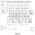
- Figure 3b depicts the typical input output signals from the microcontroller for both conventional and extended spark operation of the CDI system of the instant invention in a single cylinder engine.
- Figure 3b i), ii) and iii) show the input signals from the speed / position sensor before and after signal conditioning.
- Fig 3b v) shows multiple output pulses for ignition of prolonged duration while fig 3b iv) shows single pulse output suitable for conventional CDI operation.
- the firmware can generate both angle of advance or retardation to fulfill user defined Ignition profile.
- the ignition current can be made continuous for any ignition duration.
- the DC-DC converter should have sufficient power capability to supply the total energy required for the maximum ignition duration.
- the DC-DC converter can also be replaced by an engine mounted alternator (most of the conventional system already use one.).
- An ignition pulse from Microcontroller is synchronized with the speed/position pulses with a programmable angle of advance (or retardation).
- Firmware is developed to ignore noise at speed/position sensing port.
- the new Power Converter Topology used for generating spark for prolong duration is shown in fig. 4.
- the ignition circuit comprises of Ignition Capacitor (4.1) connected in series with the primary of ignition coil (4.2), while the other end is of capacitor connected to the mid point of series combination of two controllable power electronic switches.
- S+ (4.3) and S- (4.4) realized by two IGBTs.
- MOSFETs / BJTs can also be used.
- the collector (drain) of the Top switch S+ (4.3) is connected to positive (4.5) of DC-DC converter (or rectified output from engine mounted permanent magnet alternator).
- the emitter (source) of S- (4.4) is connected to the negative terminal (4.6) of DC-DC converter and the other end of ignition coil is connected to common ground.
- the control terminals of the switches are driven by Half bridge Driver (such as ST's L6384) (4.7) controlled by microcontroller programmed to switch them alternatively at a particular piston position depending on the speed of engine.
- the ignition duration is also programmed to be a function of engine speed.
- Each of the Power devices S+ (4.3) and S- (4.4) turns ON if there is a proper voltage at gate with respect to the emitter of the device. However the voltage of emitter of S+ (4.3) is floating.
- the half bridge driver has the capability to switch both top and Bottom device with out any isolated supply. It derives its own power supply (Vcc) by means of an internal zener and has an bootstrap arrangement for generating supply voltage for the floating HVG driver.
- the capacitors C B (4.8), C d (4.9) and Resistor R d (4.10) and R clamp (4.11) are required for operation of the Half Bridge. Different set of components may be required if a different half bridge driver is used.
- Ignition Signal (4.12) is fed to pin3 (IN) of the Half Bridge Drive (4.7) through a low pass filter made of resistor capacitor combination of Rf (4.13) and Cf (4.14). The use of this filter is optional.
- the HVG driver output of L6384 is in phase with input at IN pin while LVG driver output is out of phase.
- the alternative switching of the devices causes damped oscillatory ignition current charging and discharging current in capacitor and ignition coil primary resulting in ignition current in the spark plug connected to the ignition coil secondary.
- the ignition current is shown in fig. 4a.
- the current is series of damped sinusoid.
- the oscillatory current waveforms shown in fig. 4a are repetitive and are caused by alternative charging and discharging of the Capacitor caused by corresponding to switching of top and bottom IGBTs as explained in fig 4a.
- the capacitor need not be charged to start ignition.
- a train of such ignition current makes the spark extendable to any length of time.
- the topology also facilitates production of multi-spark with any delay between sparks Peak current of this LC oscillation is determined by total circuit resistance, while the time period of oscillation is determined by Leq*C ,where Leq is the equivalent inductance of the coil. Negative peak of the current is caused by discharge of C through the bottom IGBT. Oscillation damps out due to energy consumption of Spark plug and the coil. Immediately after the discharge oscillation dies out, the top IGBT (s+) is turned on causing a fresh oscillation and extending the spark duration.
- the Supply e.g. DC_DC converter
- the ignition duration can also be controlled by turning off corresponding switch when a oscillation is in progress. However, this can be preferably done at zero crossing of ignition current when the capacitor is totally charged or discharged.
- the conventional ignition coil used does not have isolation between primary and secondary.
- the merit of the topology is that it does not require the isolation.
- Figures 5a to 5e show equivalent circuits used for a quantitative analysis.
- the ignition coil can be modeled as a step-up transformer and the spark plug as a Resistive load, which switches on if the voltage is sufficiently large and remains on till the voltage across air-gap becomes steady at zero.
- the equivalent circuit of the spark plug and ignition coil is shown in fig 5a.
- R'arc is arc resistance referred to primary of coil.
- the approximate equivalent circuit of Ignition coil is shown in fig 5b.
- Fig 5c shows the equivalent circuit for the circuit with the coil.
- This equation can be used to determine the time each switch must be on to obtain desired ignition current profile.
- the first term represents loss in the system while the second term represents the energy available in the air gap.
- Figure 6 shows the converter output and ignition current waveform determined experimentally for duration of 14ms. This burst of ignition current is positioned at a predetermined angle of advance with respect to top dead center.
- Fig. 6a shows the expanded view of output voltage and current. The Waveforms show the ability of the topology to produce ignition current for prolonged duration . The ignition current is also similar to the Primary current. It is evident from fig. 6a that the ignition current is continuous during the whole duration; fresh cycle of oscillation begins before the previous cycle dies down.
Abstract
Description
- This invention relates to an improved Capacitor Discharge Ignition (CDI) system capable of producing continuous ignition sparks of any desired duration.
- Automotive ignition systems produce high voltage electrical discharges at the terminals of one or more spark plugs to ignite a compressed air fuel mixture. The electrical discharge is required to be produced when the piston is at a particular physical position inside the cylinder. The spark intensity must also be independent of the engine speed. Further, in order to optimize engine performance, improve fuel economy and minimize polluting effluents the time of occurrence and duration of the spark should be controllable in accordance with a defined discharge profile.
- There are primarily two types of ignition systems in use today - inductive ignition systems and capacitive discharge ignition (CDI) systems.
- In the inductive ignition system the ignition voltage is generated by sudden interruption of current following through the primary of the ignition coil. The main disadvantage of the Inductive ignition system is that the ignition energy falls of at high engine speed.
- In Capacitive Discharge Ignition (CDI) system the ignition voltage is generated by discharging a charged capacitor through the ignition coil primary by an electronic switch. The capacitor is initially charged to a high voltage from a high voltage d.c. source. At present, the Capacitive Discharge Ignition (CDI) system is generally employed in two wheelers to meet new emission norms and to offer improved fuel economy. Variants of CDI system are also used in cars and for racing application.
- Modern CDI systems also employ microcontrollers / microprocessors to provide engine parameter dependent ignition timings.
- In order to increase spark energy and better combustion of fuel some CDI systems also employ intermittent multi-spark techniques. Several other improvements have been described in various US patents.
- US patent 3,340,861 describes an improved inductive ignition system in which a ballast resistor is eliminated. This invention however still suffers from the limitations of inductive ignition systems at high engine speed.
- US patent 3,620,201, US patent 3,658,044 and US patent 3,838,328 describe various systems for producing multiple spark ignition in CDI systems. However, none of these systems are capable of producing continuous sparks or sparks of long duration.
- Similarly, US patent 4,228,778 describes a system for extending the spark duration in CDI systems. However, this invention is also not capable of very long duration, as the capacitor needs time for charging between consecutive discharges.
- US patent 4,738,239 outlines a system for enabling the use of power MOSFETS in inductive discharge systems. It does not offer any improvement in spark duration.
- US patent 4,922,883 and 5,220,901 define additional systems for providing multiple sparks and extended sparks in CDI systems respectively. However, these systems are not capable of continuous sparks nor can be discharge time be controlled to any desired value.
- US patent 6,167,875 provides a solution for adjusting the number of ignitions per cycle per cylinder depending upon the nature of the fuel-air mixture at low and high engine speeds. However, this solution is not capable of enabling continuous sparks of any desired duration.
- The object of the present invention is to produce continuous ignition current for any desired duration.
- To achieve the said objective this invention provides an improved Capacitor Discharge Ignition (CDI) system capable of generating intense continuous electrical discharge at spark gap for any desired duration, comprising:
- an ignition capacitor means connected at one end to the primary of an ignition coil means and at the other end to,
- an input terminal of a first controllable power switching means the output terminal of which is connected to,
- the common terminal of a high voltage d.c. source means which generates a stable high dc voltage, the other end of said primary of ignition coil means also being connected to said common terminal,
- a control means connected to the control terminal of said first controllable power switching means, and
- a spark gap connected across the secondary of said ignition coil means,
- a second controllable power switching means with its input terminal connected to the output terminal of said high voltage d.c. source means, its output terminal connected to the input terminal of said first power switching means, and its control terminal connected to a second output of said control means,
- The said high voltage d.c. source means is a dc-dc converter that produces a stable high voltage dc output independent of the variation in the voltage from said primary power source.
- The said first controllable power switching means and said second controllable power switching means are electronic power switching devices.
- The said switching devices include Insulated gate Bipolar Transistors (IGBT) or Power MOSFETS or power Bipolar Junction Transistors (BJT).
- The said control means is a microcontroller with a half bridge driver for driving said controllable power switching means.
- The said control means includes triggering control means for controlling ignition in accordance with a desired ignition profile.
- The said control means includes triggering control means for controlling ignition in accordance with signals obtained from one or more sensors monitoring various parameters including piston position, engine speed, throttle position, emission quality, type of fuel.
- The said triggering control means includes a data storage means containing the triggering profile data.
- The said triggering control means determines the optimal triggering based on triggering data contained in said data storage means.
- The said triggering control means is signal processing means for conditioning the signals received from said sensors.
- The said ignition profile defines ignition occurrence and duration values with respect to various piston positions and engine speeds.
- The said ignition profile provides larger ignition duration during cold starting and at low speed so as to produce fewer pollutants and ensure reliable operation.
- The above improved Capacitor Discharge Ignition (CDI) system is applied to engines using alternative fuels requiring long ignition duration.
- The said high-voltage d.c. source means is an engine-domain alternator.
- The invention will now be described with reference to the accompanying drawings:
- FIG. 1 shows a conventional Capacitor Discharge Ignition (CDI) system;
- FIG. 2 shows the improved CDI system according to this invention;
- FIG. 3 shows a diagram of ignition timings;
- FIG. 3a shows a sample triggering profile;
- FIG. 3b shows sample input and output waveforms for an ignition system for a single cylinder, according to this invention;
- FIG. 4 shows a preferred embodiment of a power converter according to the present invention;
- FIG. 4a shows a sample ignition current profile for two consecutive cycles, for the ignition system of the present invention;
- FIGS. 5a to 5e show equivalent circuits for various conditions during operation;
- FIG. 6 shows a set of waveforms for the improved CDI system according to this invention;
- FIG. 6a shows an expanded view of the waveform of figure 6.
-
- Figure 1 shows a typical conventional CDI system, an Application Specific Device (ASD) (1.1) charges Ignition Capacitor (1.2) by supplying rectified high voltage d.c. generated from the high voltage AC supplied by supply coil (1.3). A magnetic pick-up (1.4) monitors piston position and supplies a triggering signal to ASD (1.1) after suitable signal conditioning by conditioning ckt (1.5). This triggering signal causes ASD (1.1) to discharge Ignition Capacitor (1.2) through the primary winding of Ignition Transformer (1.6) causing an ignition spark across spark plug (1.7) with a typical ignition current profile (1.8). The ignition transformer (1.6) typically produces a voltage in excess of 10 KV to breakdown the air gap of the spark plug. The resistance of the air-gap falls to around 50 ohms once the arc strikes. At this point the current is limited only by the impedance of the Ignition transformer and most of the energy is dissipated in the Ignition Transformer itself. The angle of advance, which is the position of the piston with respect to Top Dead Centre (TDC), measured in angular degrees, at which the ignition is initiated, is a fixed value irrespective of engine speed. The signal conditioning circuit (1.5) is used to filter out the effect of EMI and noise from the signal obtained from magnetic pick up (1.4). Typically the spark duration is a short 100-200 microseconds and the spark gap current is 20-30 mA. Such an arrangement is generally suitable for small engine running with a rich fuel-air mixture.
- All the energy stored in the capacitor (=CV2/2) is discharged through the ignition coil by an electronic switch with in a very short time. The ignition coil and the capacitor forms a LC circuit producing a damped oscillatory current for few cycles.
- Figure 2 shows a preferred embodiment of a CDI system according to the present invention.
- A DC voltage of 225V is derived by a DC-DC converter (2.3) form 12V battery (7V-12V) (2.2), which is charged by regulator supplied by engine mounted alternator (2.1). The DC-DC converter gives stable voltage irrespective of the speed of engine where as the output voltage from conventional engine mounted magneto is speed dependant.
- This voltage is used to supply a Power converter (2.4) using a new topology. The voltage supplied by the DC-DC converter is typically in the range of 120V- 400V, the actual value being dependant on the rating of the Ignition Coil (2.9) used. This voltage powers up the Power converter (2.4). A Micro-controller (2.7) is used to generate the control signal for the power converter. The microcontroller supply is derived from the battery through a low drop regulator (2.5) while speed signal conditioning circuit (2.6) is directly powered by battery with adequate filter to suppress noise.
- A ROM (2.8) stores ignition profile data used by the microcontroller (2.7) to generate the signals for controlling Power Converter (2.4) in relation to the speed / position signal received from the sensor (2.9) mounted on the crankshaft (2.10), after signal conditioning by signal conditioning circuit (2.6). The Power Converter (2.4) charges and discharges Ignition Capacitor (2.11) through the primary of Ignition coil (2.9) under control of the microcontroller (2.7). The Power Converter (2.4) is such that ignition current is produced during both the charging and discharging of the Ignition Capacitor (2.11) resulting in a continuous spark of any desired duration.
- Figure 3 shows the diagrammatic representation of timing of Ignition with respect to top dead center of a single cylinder engine. A positive and negative sinusoidal pulse is obtained at the output of the variable reluctor sensor (3.1) with every revolution of the engine. The width and dimension of the pulses depends on the physical dimension of the sensor. The sensor is generally mounted at 5 - 10 degrees ahead of top dead center. Apart from Speed the sensor signal also provides the current position of the piston (3.2).
- The compressed fuel-air mixture is generally ignited before the piston moves to the Top Dead Center (TDC) in order to generate maximum thrust just after the piston moves away from TDC. This is generally measured in terms of degrees before TDC and known as angle of advance. In modern engine control system normally this is varied with engine speed in order to ensure complete combustion of fuel, fuel economy, production of less pollutants (nitrogen dioxide, Hydrocarbons, Carbon monoxide etc.).
- A sample ignition profile is shown in fig. 3a. This profile is user defined. Only the points of inflexion (corner points) of the ignition profiles are stored. Other points are calculated along the straight line of the profile. Engine speed along with acceleration /deceleration, throttle position other operating conditions can be used to compute the actual angle of advance. It is also possible to store multiple such profiles and one of these can be selected dynamically depending on other factors like throttle position etc. Throttle position can be sensed by a suitably mounted potentiometer. DC-DC converter output voltage can also be sensed by Analog to Digital converter of the microcontroller for finer adjustments.
- Figure 3b depicts the typical input output signals from the microcontroller for both conventional and extended spark operation of the CDI system of the instant invention in a single cylinder engine. Figure 3b i), ii) and iii) show the input signals from the speed / position sensor before and after signal conditioning. Fig 3b v) shows multiple output pulses for ignition of prolonged duration while fig 3b iv) shows single pulse output suitable for conventional CDI operation. The firmware can generate both angle of advance or retardation to fulfill user defined Ignition profile.
- The ignition current can be made continuous for any ignition duration. The DC-DC converter should have sufficient power capability to supply the total energy required for the maximum ignition duration. The DC-DC converter can also be replaced by an engine mounted alternator (most of the conventional system already use one.). An ignition pulse from Microcontroller is synchronized with the speed/position pulses with a programmable angle of advance (or retardation). Firmware is developed to ignore noise at speed/position sensing port.
- The new Power Converter Topology used for generating spark for prolong duration is shown in fig. 4. The ignition circuit comprises of Ignition Capacitor (4.1) connected in series with the primary of ignition coil (4.2), while the other end is of capacitor connected to the mid point of series combination of two controllable power electronic switches. S+ (4.3) and S- (4.4) realized by two IGBTs. However, MOSFETs / BJTs can also be used. The collector (drain) of the Top switch S+ (4.3) is connected to positive (4.5) of DC-DC converter (or rectified output from engine mounted permanent magnet alternator). The emitter (source) of S- (4.4) is connected to the negative terminal (4.6) of DC-DC converter and the other end of ignition coil is connected to common ground. The control terminals of the switches are driven by Half bridge Driver (such as ST's L6384) (4.7) controlled by microcontroller programmed to switch them alternatively at a particular piston position depending on the speed of engine. The ignition duration is also programmed to be a function of engine speed.
- Each of the Power devices S+ (4.3) and S- (4.4) turns ON if there is a proper voltage at gate with respect to the emitter of the device. However the voltage of emitter of S+ (4.3) is floating. The half bridge driver has the capability to switch both top and Bottom device with out any isolated supply. It derives its own power supply (Vcc) by means of an internal zener and has an bootstrap arrangement for generating supply voltage for the floating HVG driver. The capacitors CB (4.8), Cd (4.9) and Resistor Rd (4.10) and Rclamp (4.11) are required for operation of the Half Bridge. Different set of components may be required if a different half bridge driver is used.
- Ignition Signal (4.12) is fed to pin3 (IN) of the Half Bridge Drive (4.7) through a low pass filter made of resistor capacitor combination of Rf (4.13) and Cf (4.14). The use of this filter is optional. The HVG driver output of L6384 is in phase with input at IN pin while LVG driver output is out of phase.
- The alternative switching of the devices, with a small dead time (1-4 microsecond), causes damped oscillatory ignition current charging and discharging current in capacitor and ignition coil primary resulting in ignition current in the spark plug connected to the ignition coil secondary.
- The ignition current is shown in fig. 4a. The current is series of damped sinusoid. The oscillatory current waveforms shown in fig. 4a are repetitive and are caused by alternative charging and discharging of the Capacitor caused by corresponding to switching of top and bottom IGBTs as explained in fig 4a. Thus, unlike conventional system the capacitor need not be charged to start ignition.
- A train of such ignition current makes the spark extendable to any length of time. The topology also facilitates production of multi-spark with any delay between sparks Peak current of this LC oscillation is determined by total circuit resistance, while the time period of oscillation is determined by Leq*C ,where Leq is the equivalent inductance of the coil. Negative peak of the current is caused by discharge of C through the bottom IGBT. Oscillation damps out due to energy consumption of Spark plug and the coil. Immediately after the discharge oscillation dies out, the top IGBT (s+) is turned on causing a fresh oscillation and extending the spark duration. The Supply (e.g. DC_DC converter) should be stiff enough to start the fresh oscillation cycle.
- Waveform in fig. 4a shows that spark gap current flows practically for whole duration. Once the arc strikes the air ionizes thus the air gap resistance falls enabling the current to oscillate even though the output voltage across air-gap falls. It can be observed that fresh cycle of oscillation can also be started even before the previous oscillation has not damped out. As for example, the discharge cycle can also be started at t = π or 3π instead of t = T(≅ 5π) to increase the r.m.s. value of the current wave form. This can also be used to fine-tune the total ignition duration.
- The ignition duration can also be controlled by turning off corresponding switch when a oscillation is in progress. However, this can be preferably done at zero crossing of ignition current when the capacitor is totally charged or discharged.
- The conventional ignition coil used does not have isolation between primary and secondary. The merit of the topology is that it does not require the isolation.
- Figures 5a to 5e show equivalent circuits used for a quantitative analysis.
- The ignition coil can be modeled as a step-up transformer and the spark plug as a Resistive load, which switches on if the voltage is sufficiently large and remains on till the voltage across air-gap becomes steady at zero. The equivalent circuit of the spark plug and ignition coil is shown in fig 5a. R'arc is arc resistance referred to primary of coil. The approximate equivalent circuit of Ignition coil is shown in fig 5b. Fig 5c shows the equivalent circuit for the circuit with the coil.
- There are two cases of switching:
- The capacitor is not charged; i.e. Vc = 0 and top-switch closes resulting in charging current (fig 5d).
- The capacitor is charged; i.e. Vc=Vdc and bottom switch closes setting a discharging current (fig 5e).
- The mesh equations are :
- For fig 5d
- And for fig 5e
- Differentiating the 2nd equation and diving by L we have,
- A solution of this equation is of the form I =A1es1t+ A2 es2t substituting this we have
- When α <ω0, the system is under damped and produces oscillatory current for step input and s1 and s2 are complex conjugates.
- Or i(t) = e-
α t(A1ejβ t + A2e-jβ t) = e-α t (A3cosβt+ A4sinβt) ; for discharge (fig.1d.) where A1, A2, A3, A4 are constants. - Thus i = ± Vdc / βL *e-
α t sinβt or the general eqn. for multiple charge and discharge cycle is - This equation can be used to determine the time each switch must be on to obtain desired ignition current profile.
- Since the stored energy in the coil is zero after a charge or discharge oscillation, the energy equation is
- The first term represents loss in the system while the second term represents the energy available in the air gap.
- Figure 6 shows the converter output and ignition current waveform determined experimentally for duration of 14ms. This burst of ignition current is positioned at a predetermined angle of advance with respect to top dead center. Fig. 6a shows the expanded view of output voltage and current. The Waveforms show the ability of the topology to produce ignition current for prolonged duration .The ignition current is also similar to the Primary current. It is evident from fig. 6a that the ignition current is continuous during the whole duration; fresh cycle of oscillation begins before the previous cycle dies down.
Claims (14)
- An improved Capacitor Discharge Ignition (CDI) system capable of generating intense continuous electrical discharge at spark gap for any desired duration, comprising:characterized in that it includes:an ignition capacitor means connected at one end to the primary of an ignition coil means and at the other end to,an input terminal of a first controllable power switching means the output terminal of which is connected to,the common terminal of a high voltage d.c. source means which generates a stable high dc voltage, the other end of said primary of ignition coil means also being connected to said common terminal,a control means connected to the control terminal of said first controllable power switching means, anda spark gap connected across the secondary of said ignition coil means,the arrangement being such that said first controllable power switching means is used for discharging said discharge capacitor and said second controllable power switching means causes charging of said discharge capacitor, thereby enabling an ignition current through said ignition coil for any desired number of cycles during both the charge and discharge cycles of said discharge capacitor.a second controllable power switching means with its input terminal connected to the output terminal of said high voltage d.c. source means, its output terminal connected to the input terminal of said first power switching means, and its control terminal connected to a second output of said control means,
- An improved Capacitor Discharge Ignition (CDI) system as claimed in claim 1 wherein said high voltage d.c. source means is a dc-dc converter that produces a stable high voltage dc output independent of the variation in the voltage from said primary power source.
- An improved Capacitor Discharge Ignition (CDI) system as claimed in claim 1 wherein said first controllable power switching means and said second controllable power switching means are electronic power switching devices.
- An improved Capacitor Discharge Ignition (CDI) system as claimed in claim 3 wherein said switching devices include Insulated gate Bipolar Transistors (IGBT) or Power MOSFETS or power Bipolar Junction Transistors (BJT).
- An improved Capacitor Discharge Ignition (CDI) system as claimed in claim 1 wherein said control means is a microcontroller with a half bridge driver for driving said controllable power switching means.
- An improved Capacitor Discharge Ignition (CDI) system as claimed in claim 1 wherein said control means includes triggering control means for controlling ignition in accordance with a desired ignition profile.
- An improved Capacitor Discharge Ignition (CDI) system as claimed in claim 1 wherein said control means includes triggering control means for controlling ignition in accordance with signals obtained from one or more sensors monitoring various parameters including piston position, engine speed, throttle position, emission quality, type of fuel.
- An improved Capacitor Discharge Ignition (CDI) system as claimed in claim 5 wherein said triggering control means includes a data storage means containing the triggering profile data.
- An improved Capacitor Discharge Ignition (CDI) system as claimed in claim 8 wherein said triggering control means determines the optimal triggering based on triggering data contained in said data storage means.
- An improved Capacitor Discharge Ignition (CDI) system as claimed in claim 6 wherein said triggering control means is signal processing means for conditioning the signals received from said sensors.
- An improved Capacitor Discharge Ignition (CDI) system as claimed in claim 6 wherein said ignition profile defines ignition occurrence and duration values with respect to various piston positions and engine speeds.
- An improved Capacitor Discharge Ignition (CDI) system as claimed in claim 11 wherein said ignition profile provides larger ignition duration during cold starting and at low speed so as to produce fewer pollutants and ensure reliable operation.
- An improved Capacitor Discharge Ignition (CDI) system as claimed in claim 1 applied to engines using alternative fuels requiring long ignition duration.
- An improved Capacitor Discharge Ignition (CDI) system as claimed in claim 1 wherein said high-voltage d.c. source means is an engine-domain alternator.
Applications Claiming Priority (2)
| Application Number | Priority Date | Filing Date | Title |
|---|---|---|---|
| INDE09912001 | 2001-09-27 | ||
| IN991DE2001 | 2001-09-27 |
Publications (2)
| Publication Number | Publication Date |
|---|---|
| EP1298320A2 true EP1298320A2 (en) | 2003-04-02 |
| EP1298320A3 EP1298320A3 (en) | 2004-10-20 |
Family
ID=11097116
Family Applications (1)
| Application Number | Title | Priority Date | Filing Date |
|---|---|---|---|
| EP02021534A Ceased EP1298320A3 (en) | 2001-09-27 | 2002-09-26 | Capacitor discharge ignition (CDI) system |
Country Status (2)
| Country | Link |
|---|---|
| US (1) | US6662792B2 (en) |
| EP (1) | EP1298320A3 (en) |
Cited By (3)
| Publication number | Priority date | Publication date | Assignee | Title |
|---|---|---|---|---|
| EP1387084A3 (en) * | 2002-08-02 | 2006-09-13 | DUCATI ENERGIA S.p.A. | Inductive ignition system with digital control |
| WO2014060153A1 (en) * | 2012-10-15 | 2014-04-24 | Continental Automotive Gmbh | Device and method for firing a spark plug of a motor vehicle |
| US9856800B2 (en) | 2013-11-22 | 2018-01-02 | Nxp Usa, Inc. | Ignition control device having an electronic fuel injection (EFI) mode and a capacitive discharge ignition (CDI) mode |
Families Citing this family (11)
| Publication number | Priority date | Publication date | Assignee | Title |
|---|---|---|---|---|
| US7017565B2 (en) * | 2004-03-17 | 2006-03-28 | Fuller Gerald D | Supplemental capacitive discharge ignition system |
| ITMI20041015A1 (en) * | 2004-05-21 | 2004-08-21 | Ducati Energia Spa | INDUCTIVE IGNITION SYSTEM FOR INTERNAL COMBUSTION ENGINES |
| DE102005038198B4 (en) * | 2005-08-12 | 2021-10-07 | Andreas Stihl Ag & Co. Kg | Ignition circuit with a high-energy spark for an internal combustion engine |
| JP4803008B2 (en) * | 2006-12-05 | 2011-10-26 | 株式会社デンソー | Ignition control device for internal combustion engine |
| US7401603B1 (en) * | 2007-02-02 | 2008-07-22 | Altronic, Inc. | High tension capacitive discharge ignition with reinforcing triggering pulses |
| US8031838B2 (en) | 2009-01-29 | 2011-10-04 | The Invention Science Fund I, Llc | Diagnostic delivery service |
| US8130904B2 (en) | 2009-01-29 | 2012-03-06 | The Invention Science Fund I, Llc | Diagnostic delivery service |
| JP5295305B2 (en) * | 2011-05-16 | 2013-09-18 | 三菱電機株式会社 | Ignition device |
| US9816476B2 (en) * | 2013-07-17 | 2017-11-14 | Delphi Technologies, Inc. | Ignition system for spark ignition engines and method of operating same |
| WO2016175733A1 (en) * | 2015-04-25 | 2016-11-03 | Lamar William Paul | High speed capacitor discharge ignition system |
| SE544004C2 (en) | 2020-12-22 | 2021-10-26 | Sem Ab | Electronic circuit and capacitor discharge system comprising electronic circuit |
Citations (9)
| Publication number | Priority date | Publication date | Assignee | Title |
|---|---|---|---|---|
| US3340861A (en) | 1964-09-16 | 1967-09-12 | Rca Corp | Transistorized ignition circuit |
| US3620201A (en) | 1969-10-07 | 1971-11-16 | Glenn B Warren | Solid state multispark ignition system |
| US3658044A (en) | 1970-12-08 | 1972-04-25 | Alden L Safstrom | Capacitor discharge ignition system |
| US3838328A (en) | 1973-03-19 | 1974-09-24 | W Lundy | Capacitive discharge ignition system |
| US4228778A (en) | 1977-09-22 | 1980-10-21 | Robert Bosch Gmbh | Extended spark capacitor discharge ignition system |
| US4738239A (en) | 1987-07-31 | 1988-04-19 | Delco Electronics Corporation | Ignition system |
| US4922883A (en) | 1987-10-29 | 1990-05-08 | Aisin Seiki Kabushiki Kaisha | Multi spark ignition system |
| US5220901A (en) | 1991-10-09 | 1993-06-22 | Mitsubishi Denki Kabushiki Kaisha | Capacitor discharge ignition system with inductively extended discharge time |
| US6167875B1 (en) | 1996-06-21 | 2001-01-02 | Outboard Marine Corporation | Multiple spark capacitive discharge ignition system for an internal combustion engine |
Family Cites Families (9)
| Publication number | Priority date | Publication date | Assignee | Title |
|---|---|---|---|---|
| US4115758A (en) * | 1975-04-21 | 1978-09-19 | Luteran Frank K | Visual test indicator for ignition systems |
| US4155340A (en) * | 1977-03-28 | 1979-05-22 | Gulf & Western Manufacturing Company | Solid state ignition system |
| US4562823A (en) * | 1983-07-15 | 1986-01-07 | Nippon Soken, Inc. | Ignition device for internal combustion engine |
| JPH073944B2 (en) * | 1988-09-16 | 1995-01-18 | 富士電機株式会社 | Method for driving insulated gate semiconductor device |
| US5056496A (en) * | 1989-03-14 | 1991-10-15 | Nippondenso Co., Ltd. | Ignition system of multispark type |
| US5513618A (en) * | 1992-09-17 | 1996-05-07 | Enox Technologies, Inc. | High performance ignition apparatus and method |
| JP3216966B2 (en) * | 1995-04-04 | 2001-10-09 | 三菱電機株式会社 | Ignition device for internal combustion engine |
| US5806504A (en) * | 1995-07-25 | 1998-09-15 | Outboard Marine Corporation | Hybrid ignition circuit for an internal combustion engine |
| US6425383B1 (en) * | 2000-07-06 | 2002-07-30 | Federal-Mogul World Wide, Inc. | Ignition coil with control and driver apparatus having reverse polarity capability |
-
2002
- 2002-09-26 EP EP02021534A patent/EP1298320A3/en not_active Ceased
- 2002-09-26 US US10/256,216 patent/US6662792B2/en not_active Expired - Lifetime
Patent Citations (9)
| Publication number | Priority date | Publication date | Assignee | Title |
|---|---|---|---|---|
| US3340861A (en) | 1964-09-16 | 1967-09-12 | Rca Corp | Transistorized ignition circuit |
| US3620201A (en) | 1969-10-07 | 1971-11-16 | Glenn B Warren | Solid state multispark ignition system |
| US3658044A (en) | 1970-12-08 | 1972-04-25 | Alden L Safstrom | Capacitor discharge ignition system |
| US3838328A (en) | 1973-03-19 | 1974-09-24 | W Lundy | Capacitive discharge ignition system |
| US4228778A (en) | 1977-09-22 | 1980-10-21 | Robert Bosch Gmbh | Extended spark capacitor discharge ignition system |
| US4738239A (en) | 1987-07-31 | 1988-04-19 | Delco Electronics Corporation | Ignition system |
| US4922883A (en) | 1987-10-29 | 1990-05-08 | Aisin Seiki Kabushiki Kaisha | Multi spark ignition system |
| US5220901A (en) | 1991-10-09 | 1993-06-22 | Mitsubishi Denki Kabushiki Kaisha | Capacitor discharge ignition system with inductively extended discharge time |
| US6167875B1 (en) | 1996-06-21 | 2001-01-02 | Outboard Marine Corporation | Multiple spark capacitive discharge ignition system for an internal combustion engine |
Cited By (3)
| Publication number | Priority date | Publication date | Assignee | Title |
|---|---|---|---|---|
| EP1387084A3 (en) * | 2002-08-02 | 2006-09-13 | DUCATI ENERGIA S.p.A. | Inductive ignition system with digital control |
| WO2014060153A1 (en) * | 2012-10-15 | 2014-04-24 | Continental Automotive Gmbh | Device and method for firing a spark plug of a motor vehicle |
| US9856800B2 (en) | 2013-11-22 | 2018-01-02 | Nxp Usa, Inc. | Ignition control device having an electronic fuel injection (EFI) mode and a capacitive discharge ignition (CDI) mode |
Also Published As
| Publication number | Publication date |
|---|---|
| US6662792B2 (en) | 2003-12-16 |
| US20030056773A1 (en) | 2003-03-27 |
| EP1298320A3 (en) | 2004-10-20 |
Similar Documents
| Publication | Publication Date | Title |
|---|---|---|
| JP5840714B2 (en) | Method for measuring at least one parameter relating to a gaseous substance | |
| US5207208A (en) | Integrated converter high power CD ignition | |
| EP1298320A2 (en) | Capacitor discharge ignition (CDI) system | |
| US4487177A (en) | Apparatus and method for starting a diesel engine using plasma ignition plugs | |
| US8807124B2 (en) | Ignition apparatus | |
| JPH0135177B2 (en) | ||
| JP2597126B2 (en) | Method and apparatus for generating ignition spark in an internal combustion engine | |
| US4326493A (en) | Multiple spark discharge ignition system | |
| US5513618A (en) | High performance ignition apparatus and method | |
| JPH1172074A (en) | Ignition device of internal combustion engine | |
| US5429103A (en) | High performance ignition system | |
| CA1038028A (en) | Ferroresonant capacitor discharge ignition system | |
| JP5253144B2 (en) | Ignition device for internal combustion engine | |
| JP2004525302A (en) | Ignition device for internal combustion engine | |
| JPH0344228B2 (en) | ||
| US11692502B2 (en) | Engine ignition method and engine ignition device | |
| JP2011064191A (en) | Plasma ignition device, and method for controlling the same | |
| US6953032B2 (en) | Combustion engine and ignition circuit for a combustion engine | |
| US20030084889A1 (en) | Make voltage ignition coil and method of making | |
| EP0142478A1 (en) | Method and apparatus in electronic ignition systems for internal combustion engine | |
| JP2010101212A (en) | Ignition device for internal combustion engine | |
| US20050016511A1 (en) | Capacitive discharge ignition system | |
| JP3116964B2 (en) | Engine ignition device | |
| JP2927128B2 (en) | Ignition system for condenser discharge type multi-cylinder internal combustion engine | |
| JP2569852B2 (en) | Capacitor discharge type ignition system for internal combustion engine |
Legal Events
| Date | Code | Title | Description |
|---|---|---|---|
| PUAI | Public reference made under article 153(3) epc to a published international application that has entered the european phase |
Free format text: ORIGINAL CODE: 0009012 |
|
| AK | Designated contracting states |
Kind code of ref document: A2 Designated state(s): AT BE BG CH CY CZ DE DK EE ES FI FR GB GR IE IT LI LU MC NL PT SE SK TR Designated state(s): AT BE BG CH CY CZ DE DK EE ES FI FR GB GR IE IT LI LU MC NL PT SE SK TR |
|
| AX | Request for extension of the european patent |
Extension state: AL LT LV MK RO SI |
|
| PUAL | Search report despatched |
Free format text: ORIGINAL CODE: 0009013 |
|
| AK | Designated contracting states |
Kind code of ref document: A3 Designated state(s): AT BE BG CH CY CZ DE DK EE ES FI FR GB GR IE IT LI LU MC NL PT SE SK TR |
|
| AX | Request for extension of the european patent |
Extension state: AL LT LV MK RO SI |
|
| 17P | Request for examination filed |
Effective date: 20050418 |
|
| AKX | Designation fees paid |
Designated state(s): AT BE BG CH CY CZ DE DK EE ES FI FR GB GR IE IT LI LU MC NL PT SE SK TR |
|
| 17Q | First examination report despatched |
Effective date: 20061228 |
|
| STAA | Information on the status of an ep patent application or granted ep patent |
Free format text: STATUS: THE APPLICATION HAS BEEN REFUSED |
|
| 18R | Application refused |
Effective date: 20091002 |