EP1301645B1 - Aluminum matrix composite wires, cables, and method - Google Patents
Aluminum matrix composite wires, cables, and method Download PDFInfo
- Publication number
- EP1301645B1 EP1301645B1 EP01920131A EP01920131A EP1301645B1 EP 1301645 B1 EP1301645 B1 EP 1301645B1 EP 01920131 A EP01920131 A EP 01920131A EP 01920131 A EP01920131 A EP 01920131A EP 1301645 B1 EP1301645 B1 EP 1301645B1
- Authority
- EP
- European Patent Office
- Prior art keywords
- wire
- cable
- fibers
- anyone
- aluminum
- Prior art date
- Legal status (The legal status is an assumption and is not a legal conclusion. Google has not performed a legal analysis and makes no representation as to the accuracy of the status listed.)
- Expired - Lifetime
Links
Images
Classifications
-
- C—CHEMISTRY; METALLURGY
- C04—CEMENTS; CONCRETE; ARTIFICIAL STONE; CERAMICS; REFRACTORIES
- C04B—LIME, MAGNESIA; SLAG; CEMENTS; COMPOSITIONS THEREOF, e.g. MORTARS, CONCRETE OR LIKE BUILDING MATERIALS; ARTIFICIAL STONE; CERAMICS; REFRACTORIES; TREATMENT OF NATURAL STONE
- C04B41/00—After-treatment of mortars, concrete, artificial stone or ceramics; Treatment of natural stone
- C04B41/009—After-treatment of mortars, concrete, artificial stone or ceramics; Treatment of natural stone characterised by the material treated
-
- C—CHEMISTRY; METALLURGY
- C04—CEMENTS; CONCRETE; ARTIFICIAL STONE; CERAMICS; REFRACTORIES
- C04B—LIME, MAGNESIA; SLAG; CEMENTS; COMPOSITIONS THEREOF, e.g. MORTARS, CONCRETE OR LIKE BUILDING MATERIALS; ARTIFICIAL STONE; CERAMICS; REFRACTORIES; TREATMENT OF NATURAL STONE
- C04B41/00—After-treatment of mortars, concrete, artificial stone or ceramics; Treatment of natural stone
- C04B41/45—Coating or impregnating, e.g. injection in masonry, partial coating of green or fired ceramics, organic coating compositions for adhering together two concrete elements
- C04B41/50—Coating or impregnating, e.g. injection in masonry, partial coating of green or fired ceramics, organic coating compositions for adhering together two concrete elements with inorganic materials
- C04B41/51—Metallising, e.g. infiltration of sintered ceramic preforms with molten metal
- C04B41/515—Other specific metals
- C04B41/5155—Aluminium
-
- C—CHEMISTRY; METALLURGY
- C22—METALLURGY; FERROUS OR NON-FERROUS ALLOYS; TREATMENT OF ALLOYS OR NON-FERROUS METALS
- C22C—ALLOYS
- C22C47/00—Making alloys containing metallic or non-metallic fibres or filaments
- C22C47/08—Making alloys containing metallic or non-metallic fibres or filaments by contacting the fibres or filaments with molten metal, e.g. by infiltrating the fibres or filaments placed in a mould
-
- C—CHEMISTRY; METALLURGY
- C22—METALLURGY; FERROUS OR NON-FERROUS ALLOYS; TREATMENT OF ALLOYS OR NON-FERROUS METALS
- C22C—ALLOYS
- C22C49/00—Alloys containing metallic or non-metallic fibres or filaments
- C22C49/02—Alloys containing metallic or non-metallic fibres or filaments characterised by the matrix material
- C22C49/04—Light metals
- C22C49/06—Aluminium
-
- H—ELECTRICITY
- H01—ELECTRIC ELEMENTS
- H01B—CABLES; CONDUCTORS; INSULATORS; SELECTION OF MATERIALS FOR THEIR CONDUCTIVE, INSULATING OR DIELECTRIC PROPERTIES
- H01B1/00—Conductors or conductive bodies characterised by the conductive materials; Selection of materials as conductors
- H01B1/02—Conductors or conductive bodies characterised by the conductive materials; Selection of materials as conductors mainly consisting of metals or alloys
- H01B1/023—Alloys based on aluminium
-
- H—ELECTRICITY
- H01—ELECTRIC ELEMENTS
- H01B—CABLES; CONDUCTORS; INSULATORS; SELECTION OF MATERIALS FOR THEIR CONDUCTIVE, INSULATING OR DIELECTRIC PROPERTIES
- H01B5/00—Non-insulated conductors or conductive bodies characterised by their form
- H01B5/08—Several wires or the like stranded in the form of a rope
- H01B5/10—Several wires or the like stranded in the form of a rope stranded around a space, insulating material, or dissimilar conducting material
- H01B5/102—Several wires or the like stranded in the form of a rope stranded around a space, insulating material, or dissimilar conducting material stranded around a high tensile strength core
- H01B5/105—Several wires or the like stranded in the form of a rope stranded around a space, insulating material, or dissimilar conducting material stranded around a high tensile strength core composed of synthetic filaments, e.g. glass-fibres
-
- B—PERFORMING OPERATIONS; TRANSPORTING
- B22—CASTING; POWDER METALLURGY
- B22F—WORKING METALLIC POWDER; MANUFACTURE OF ARTICLES FROM METALLIC POWDER; MAKING METALLIC POWDER; APPARATUS OR DEVICES SPECIALLY ADAPTED FOR METALLIC POWDER
- B22F2998/00—Supplementary information concerning processes or compositions relating to powder metallurgy
-
- B—PERFORMING OPERATIONS; TRANSPORTING
- B22—CASTING; POWDER METALLURGY
- B22F—WORKING METALLIC POWDER; MANUFACTURE OF ARTICLES FROM METALLIC POWDER; MAKING METALLIC POWDER; APPARATUS OR DEVICES SPECIALLY ADAPTED FOR METALLIC POWDER
- B22F2999/00—Aspects linked to processes or compositions used in powder metallurgy
-
- C—CHEMISTRY; METALLURGY
- C04—CEMENTS; CONCRETE; ARTIFICIAL STONE; CERAMICS; REFRACTORIES
- C04B—LIME, MAGNESIA; SLAG; CEMENTS; COMPOSITIONS THEREOF, e.g. MORTARS, CONCRETE OR LIKE BUILDING MATERIALS; ARTIFICIAL STONE; CERAMICS; REFRACTORIES; TREATMENT OF NATURAL STONE
- C04B2111/00—Mortars, concrete or artificial stone or mixtures to prepare them, characterised by specific function, property or use
- C04B2111/90—Electrical properties
- C04B2111/94—Electrically conducting materials
-
- Y—GENERAL TAGGING OF NEW TECHNOLOGICAL DEVELOPMENTS; GENERAL TAGGING OF CROSS-SECTIONAL TECHNOLOGIES SPANNING OVER SEVERAL SECTIONS OF THE IPC; TECHNICAL SUBJECTS COVERED BY FORMER USPC CROSS-REFERENCE ART COLLECTIONS [XRACs] AND DIGESTS
- Y10—TECHNICAL SUBJECTS COVERED BY FORMER USPC
- Y10T—TECHNICAL SUBJECTS COVERED BY FORMER US CLASSIFICATION
- Y10T428/00—Stock material or miscellaneous articles
- Y10T428/12—All metal or with adjacent metals
- Y10T428/12333—Helical or with helical component
-
- Y—GENERAL TAGGING OF NEW TECHNOLOGICAL DEVELOPMENTS; GENERAL TAGGING OF CROSS-SECTIONAL TECHNOLOGIES SPANNING OVER SEVERAL SECTIONS OF THE IPC; TECHNICAL SUBJECTS COVERED BY FORMER USPC CROSS-REFERENCE ART COLLECTIONS [XRACs] AND DIGESTS
- Y10—TECHNICAL SUBJECTS COVERED BY FORMER USPC
- Y10T—TECHNICAL SUBJECTS COVERED BY FORMER US CLASSIFICATION
- Y10T428/00—Stock material or miscellaneous articles
- Y10T428/12—All metal or with adjacent metals
- Y10T428/12431—Foil or filament smaller than 6 mils
-
- Y—GENERAL TAGGING OF NEW TECHNOLOGICAL DEVELOPMENTS; GENERAL TAGGING OF CROSS-SECTIONAL TECHNOLOGIES SPANNING OVER SEVERAL SECTIONS OF THE IPC; TECHNICAL SUBJECTS COVERED BY FORMER USPC CROSS-REFERENCE ART COLLECTIONS [XRACs] AND DIGESTS
- Y10—TECHNICAL SUBJECTS COVERED BY FORMER USPC
- Y10T—TECHNICAL SUBJECTS COVERED BY FORMER US CLASSIFICATION
- Y10T428/00—Stock material or miscellaneous articles
- Y10T428/12—All metal or with adjacent metals
- Y10T428/12465—All metal or with adjacent metals having magnetic properties, or preformed fiber orientation coordinate with shape
-
- Y—GENERAL TAGGING OF NEW TECHNOLOGICAL DEVELOPMENTS; GENERAL TAGGING OF CROSS-SECTIONAL TECHNOLOGIES SPANNING OVER SEVERAL SECTIONS OF THE IPC; TECHNICAL SUBJECTS COVERED BY FORMER USPC CROSS-REFERENCE ART COLLECTIONS [XRACs] AND DIGESTS
- Y10—TECHNICAL SUBJECTS COVERED BY FORMER USPC
- Y10T—TECHNICAL SUBJECTS COVERED BY FORMER US CLASSIFICATION
- Y10T428/00—Stock material or miscellaneous articles
- Y10T428/12—All metal or with adjacent metals
- Y10T428/12486—Laterally noncoextensive components [e.g., embedded, etc.]
-
- Y—GENERAL TAGGING OF NEW TECHNOLOGICAL DEVELOPMENTS; GENERAL TAGGING OF CROSS-SECTIONAL TECHNOLOGIES SPANNING OVER SEVERAL SECTIONS OF THE IPC; TECHNICAL SUBJECTS COVERED BY FORMER USPC CROSS-REFERENCE ART COLLECTIONS [XRACs] AND DIGESTS
- Y10—TECHNICAL SUBJECTS COVERED BY FORMER USPC
- Y10T—TECHNICAL SUBJECTS COVERED BY FORMER US CLASSIFICATION
- Y10T428/00—Stock material or miscellaneous articles
- Y10T428/12—All metal or with adjacent metals
- Y10T428/12493—Composite; i.e., plural, adjacent, spatially distinct metal components [e.g., layers, joint, etc.]
- Y10T428/12535—Composite; i.e., plural, adjacent, spatially distinct metal components [e.g., layers, joint, etc.] with additional, spatially distinct nonmetal component
- Y10T428/12583—Component contains compound of adjacent metal
- Y10T428/1259—Oxide
-
- Y—GENERAL TAGGING OF NEW TECHNOLOGICAL DEVELOPMENTS; GENERAL TAGGING OF CROSS-SECTIONAL TECHNOLOGIES SPANNING OVER SEVERAL SECTIONS OF THE IPC; TECHNICAL SUBJECTS COVERED BY FORMER USPC CROSS-REFERENCE ART COLLECTIONS [XRACs] AND DIGESTS
- Y10—TECHNICAL SUBJECTS COVERED BY FORMER USPC
- Y10T—TECHNICAL SUBJECTS COVERED BY FORMER US CLASSIFICATION
- Y10T428/00—Stock material or miscellaneous articles
- Y10T428/12—All metal or with adjacent metals
- Y10T428/12493—Composite; i.e., plural, adjacent, spatially distinct metal components [e.g., layers, joint, etc.]
- Y10T428/12535—Composite; i.e., plural, adjacent, spatially distinct metal components [e.g., layers, joint, etc.] with additional, spatially distinct nonmetal component
- Y10T428/12597—Noncrystalline silica or noncrystalline plural-oxide component [e.g., glass, etc.]
-
- Y—GENERAL TAGGING OF NEW TECHNOLOGICAL DEVELOPMENTS; GENERAL TAGGING OF CROSS-SECTIONAL TECHNOLOGIES SPANNING OVER SEVERAL SECTIONS OF THE IPC; TECHNICAL SUBJECTS COVERED BY FORMER USPC CROSS-REFERENCE ART COLLECTIONS [XRACs] AND DIGESTS
- Y10—TECHNICAL SUBJECTS COVERED BY FORMER USPC
- Y10T—TECHNICAL SUBJECTS COVERED BY FORMER US CLASSIFICATION
- Y10T428/00—Stock material or miscellaneous articles
- Y10T428/12—All metal or with adjacent metals
- Y10T428/12493—Composite; i.e., plural, adjacent, spatially distinct metal components [e.g., layers, joint, etc.]
- Y10T428/12736—Al-base component
-
- Y—GENERAL TAGGING OF NEW TECHNOLOGICAL DEVELOPMENTS; GENERAL TAGGING OF CROSS-SECTIONAL TECHNOLOGIES SPANNING OVER SEVERAL SECTIONS OF THE IPC; TECHNICAL SUBJECTS COVERED BY FORMER USPC CROSS-REFERENCE ART COLLECTIONS [XRACs] AND DIGESTS
- Y10—TECHNICAL SUBJECTS COVERED BY FORMER USPC
- Y10T—TECHNICAL SUBJECTS COVERED BY FORMER US CLASSIFICATION
- Y10T428/00—Stock material or miscellaneous articles
- Y10T428/249921—Web or sheet containing structurally defined element or component
- Y10T428/249924—Noninterengaged fiber-containing paper-free web or sheet which is not of specified porosity
- Y10T428/249927—Fiber embedded in a metal matrix
Landscapes
- Chemical & Material Sciences (AREA)
- Engineering & Computer Science (AREA)
- Materials Engineering (AREA)
- Organic Chemistry (AREA)
- Ceramic Engineering (AREA)
- Mechanical Engineering (AREA)
- Metallurgy (AREA)
- Structural Engineering (AREA)
- Inorganic Chemistry (AREA)
- Ropes Or Cables (AREA)
- Manufacture Of Alloys Or Alloy Compounds (AREA)
- Conductive Materials (AREA)
- Superconductors And Manufacturing Methods Therefor (AREA)
- Insulated Conductors (AREA)
Abstract
Description
- The present invention pertains to composite wires reinforced with substantially continuous ceramic oxide fibers within an aluminum matrix and cables incorporating such wires.
- Metal matrix composites (MMC's) have long been recognized as promising materials due to their combination of high strength and stiffness combined with low weight. MMC's typically include a metal matrix reinforced with fibers. In selection of the fiber, it is widely acknowledged that one desires reinforcement fibers possessing high strength, a high elastic modulus, and a low coefficient of thermal expansion.
- The use of metal matrix composites in the form of wires as a reinforcing member in bare overhead power transmission cables is of particular interest. The need for new materials in such cables is driven by the need to increase the power transfer capacity of existing transmission infrastructure due to load growth and changes in power flow due to deregulation. Desired performance requirements for such new materials include corrosion resistance, environmental endurance (e.g., UV and moisture), retention of strength at elevated temperatures, and creep resistance.
- Important properties for performance are elastic modulus, density, coefficient of thermal expansion, conductivity, and strength. These properties are typically governed by the choice and purity of constituents (i.e., material of the metal matrix and the fiber content) in combination with the fiber volume fraction. Of these properties, emphasis has been placed on the development of wires made from fibers with high tensile strength and stiffness. The focus on producing materials of high strength is driven in part by the assumption that in order for the composite to compete economically with conventional materials such as steel, its strength should be as high as possible. For example, in Ouchi et al., "Mechanical Properties of Composite Conductors using SiC Fiber Resinforced Aluminum Composite Wires," The Electricity Society National Symposium, 1996, which discloses an aluminum wire reinforced with high strength fiber marketed under the trade designation "NICALON," the need for MMC wires of "high strength" for use in overhead power transmission cables is described.
- There is still a need for composite materials that have suitable properties for use in a wide variety of cables, particularly overhead power transmission cables.
- The present invention relates to an aluminum matrix composite wire as defined in claim 1, a cable according to claim 7, and a method of making an aluminum matrix wire as specified in claim 6. The dependent claims relate to individual embodiments of the invention.
- Accordingly, the present invention relates to substantially continuous fiber aluminum matrix composite. Such articles include a plurality of substantially continuous, longitudinally positioned fibers contained within a matrix that includes aluminum (e.g., high purity aluminum or alloys thereof). Preferably, the matrix of the wire includes at least 99.95 percent by weight aluminum, based on the total weight of the matrix.
- The aluminum matrix composite of the present invention are formed into : wires exhibiting desirable strength-to-weight and thermal expansion characteristics, high electrical conductivity, and low modulus. Such wires are well-suited for use as core materials in power transmission cables, as they provide electrical and physical characteristics which offer improvements over power transmission cables known in the prior art.
- The materials of the present invention are for wires and cables because they provide less sag when heated due to the low coefficient of thermal expansion. Additionally, compared with steel wires or composite wires reinforced with high modulus materials, the wires of the present invention are capable of reducing the tension on supporting towers when the cables are exposed to high mechanical loads (such as combined ice and wind load) due to their low modulus.
- As used herein, the following terms are defined as:
- "Substantially continuous fiber" means a fiber having a length that is relatively infinite when compared to the average effective fiber diameter. Typically, this means that the fiber has an aspect ratio (i.e., ratio of the length of the fiber to the average effective diameter of the fiber) of at least 1 x 10⁵, preferably, at least 1 x 10⁶, and more preferably, at least 1 x 10⁷. Typically, such fibers have a length on the order of at least 50 meters, and may even have lengths on the order of kilometers or more.
- "Average effective diameter" means the true diameter of a circle having the same cross-sectional area as the measured object. For example, a circular fiber or wire has a measurable diameter from which the area may be accurately computed as πd2/4. Non-circular, elliptical, oval, or irregular shaped fibers or wires do not have a single measurable diameter, although the cross-sectional area may be measured, and then a diameter computed that would create a circle of the same cross-sectional area. This diameter of the circle is termed the effective diameter. The average effective diameter is the numerical average of several computed effective diameters.
- "Longitudinally positioned" means that the fibers are oriented in the same direction as the length of the wire.
- "Coefficient of thermal expansion (CTE)" means the rate of change of thermal
expansion over a specified temperature range measured in the longitudinal direction of the
fiber and/or wire. That is:
- thermal expansion coefficient = (change in dimensions) / (change in temperature). The instantaneous CTE value is then the slope of the thermal expansion vs. temperature graph calculated at a specific temperature (i.e., the derivative of the equation of the curve plotting thermal expansion versus temperature).
- ''Nonlinear CTE over a temperature of -75°C to 500°C" means that a second order curve fit of segments between inflections on a graph of the percent thermal expansion vs. temperature within the specified temperature range shows alternating positive and negative slopes.
- "Average tensile strength" means the numerical average of the measured tensile strengths of several fiber, wire, or cable samples.
- "Longitudinal tensile strength" means the stress at which the fiber, wire, or cable fails when tested in the direction of the major axis of the fiber, wire, or cable. This is also equal to the maximum stress applied to the sample. The stress, S, is computed as S = L/A, where L is the maximum load measured during the tensile test and A is the cross-sectional area of the sample prior to testing.
- "Modulus" means the longitudinal tensile modulus. It is the tensile stiffness of the fiber, wire, or cable as measured in the direction of the major axis of the sample. It represents the average stress per unit strain for the sample measured over a given strain increment or strain range. For the wire, modulus is measured between 0 and 0.05% strain.
- "Cable modulus" means the elastic tensile modulus of the cable. The cable
modulus is obtained by loading and unloading a cable using tensile testing apparatus to
obtain a load-unload deformation curve. The cable is loaded sufficiently so that the
constructional stretch of the cable has been taken up and the cable is elastically deformed.
The data from the unload region of the curve is used to calculate the cable modulus. This
is further described in "Theory of Wire Rope" in Testing of Wire Rope, Chapter 6, George
A. Costello, Springer-Verlag (1997). The cable modulus can be calculated from measured
load-displacement data using the following equation:
E is the calculated cable modulus
ΔF is change in measured load in the measurement region
A is the total cross - sectional area of the wire in the cable determined prior to testing e is the change in the measured elongation of the cable in the measurement region specifically,
l 0 is the initial length of the cable in the measurement region
lf is the final length of the cable in the measurement region - "Average strain to failure" means the tensile strain to failure and is the numerical
average of the measured strain to failure for several samples. The strain to failure is the
elongation or extension of the sample per unit length. It can be represented as:
e is the elongation or extension of the sample per unit length;
lf is the final gauge length of the sample; and
lo is the initial gauge length of the sample. - "Theoretical fiber strain to failure" is the strain to failure of the fiber calculated
using the average fiber tensile strength and is defined by the relationship:
-
- Thus strain = stress / modulus. For fibers available under the trade designation "NEXTEL 312," the measured average tensile stress was 1.68 GPa (244 ksi) and the modulus is reported as 151 GPa (22 Msi). Therefore the strain is 1.1 % and the theoretical fiber strain to failure is 1.1%.
- The invention will be described in more detail refering to the drawing in which:
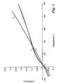
- FIG. 1 is a graph showing the percentage expansion as a function of temperature for two samples of a wire of the present invention containing fibers marketed by the 3M Company, St. Paul, MN, under the trade designation "NEXTEL 312" (lines 1 and 2) compared to a wire containing fibers marketed by the 3M Company, St. Paul, MN, under the trade designation "NEXTEL 610" (line 3).
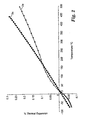
- FIG. 2 is a curve fit to the percent expansion as a function of temperature curve for the wire made from fibers marketed under the trade designation "NEXTEL 610" (line 3 of FIG. 1) and for wire made from fibers marketed under the trade designation "NEXTEL 312" (line 2 of FIG. 1) fibers of FIG. 1.
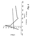
- FIG. 3 is a plot of the instantaneous CTE derived from the curve fit of FIG. 2.
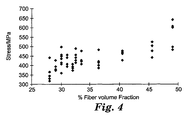
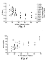
- FIG. 4 is a graph of tensile strength vs. fiber volume fraction for wire made from fibers marketed under the trade designation "NEXTEL 312" and pure aluminum.
- FIG. 5 is a graph of tensile strain to failure vs. fiber volume fraction for wire made from fibers marketed under the trade designation "NEXTEL 312" and pure aluminum. The fraction of the theoretical fiber strain to failure is shown as a second strain axis.
- FIG. 6 is a graph of the tensile modulus vs. fiber volume fraction for wires made from fibers marketed under the trade designation "NEXTEL 312" and pure aluminum.
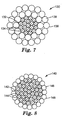
- FIGS. 7 and 8 are schematic, cross-sections of two embodiments of overhead electrical power transmission cables having composite metal matrix cores.
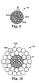
- FIG. 9 is an end view of an embodiment of a stranded cable according to the present invention with a maintaining means around the plurality of strands.
- FIG. 10 is an end view of an embodiment of an electrical power transmission cable according to the present invention.
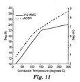
- FIG. 11 is plot of sag versus conductor temperature of a cable according to the present invention.
-
- The present invention is based on the discovery that low strength materials, produced from fibers that would not typically be considered suitable as a reinforcement can be produced and that such materials can compete directly with the high performance materials in development today for applications such as overhead electrical power transmission. The present invention provides metal composite wires, that include a plurality of substantially continuous, longitudinally positioned fibers contained within a matrix that includes aluminum (e.g., high purity aluminum or alloys thereof).
- The present invention provides composite wires and cables, that include fiber reinforced aluminum matrix composites. A composite wire according to the present invention includes a plurality of substantially continuous, longitudinally positioned, reinforcing fibers (ceramic oxide, and preferably, Al2O3-based reinforcing fibers) encapsulated within a matrix that includes aluminum and optionally one or more other metals (preferably, highly pure elemental aluminum or alloys of pure aluminum with other elements, such as copper). Preferably, at least 85% by number of the fibers are substantially continuous in a wire according to the present invention. At least one wire according to the present invention can be combined into a cable, preferably, a transmission cable.
- The substantially continuous reinforcing fibers preferably have an average effective fiber diameter of at least 5 micrometers. Preferably, the average effective fiber diameter is no greater than 50 micrometers, and more preferably, no greater than 25 micrometers.
- Preferred fibers are those that have a coefficient of thermal expansion of no more than 10 x 10-6/°C (25°C-1000°C). Typically, polycrystalline α-Al2O3 fibers have a coefficient of thermal expansion of no more than 8 x 10⁻⁶/°C. By incorporating SiO2 and B2O3 the coefficient of thermal expansion can be reduced. Because this can also reduce the tensile strength of the fibers to about 1.4 GPa, for example, it was unexpected that useful cable could be made using such fibers.
- More preferably, the fibers have an average coefficient of thermal expansion of no more than 7.9 x 10⁻⁶/°C (25°C-500°C), and most preferably, no more than 5 x 10⁻⁶/°C (25°C-500°C). Preferably, the fibers have a coefficient of thermal expansion of at least 3 x 10⁻⁶/°C (25°C-500°C), and more preferably, at least 2 x 10⁻⁶/°C (25°C-500°C).
- Preferably, the fibers have an average tensile strength of at least 1.4 GPa; more preferably, at least 1.7 GPa; even more preferably, at least 2.1 GPa; and most preferably, at least 2.8 GPa.
- Preferably, the fibers have a modulus of no greater than 240 GPa (35 Msi), and more preferably, no greater than 173 GPa (25 Msi). Preferably, fibers have a modulus of greater than 69 GPa (10 Msi).
- The elastic modulus and strength of various fibers is as follows.
Fiber Modulus (Msi (GPa)) % Elongation Tensile Strength (ksi (MPa) "NEXTEL 312" 22 (152) 1.2 250 (1720) "NEXTEL 440" 27 (186) 1.1 300 (2070) "NEXTEL 610" 54 (372) 0.8 400 (2750) "ALTEX" 30 (207) 0.9 300 (2070) "ALMAX" 48 (331) 0.5 260 (1790) - Preferably, fibers according to the present invention have an average strain to failure of no greater than 2.5%, more preferably, no greater than 1.2%, and most preferably, no greater than 1.0%.
- Examples of substantially continuous ceramic oxide fibers that may be useful for making aluminum matrix composite materials according to the present invention include ceramic oxide (e.g., aluminoborosilicate) fibers. Typically, the ceramic oxide fibers are crystalline ceramics and/or a mixture of crystalline ceramic and glass (i.e., a fiber may contain both crystalline ceramic and glass phases).
- Ceramic fibers are available commercially as single filaments, or grouped together in, for example, yams or tows. Tows are well known in the fiber art and refer to a plurality of (individual) fibers (typically, at least 100 fibers, and more typically, at least 400 fibers) collected in a rope-like form. Yams or tows preferably include at least 780 individual fibers per tow, and more preferably at least 2600 individual fibers per tow. Ceramic fibers are available in a variety of lengths, including 300 meters and larger. The fibers may have a cross-sectional shape that is circular or elliptical.
- Fibers including suitable aluminoborosilicate fibers are described in U.S.-A-3,795,524. The aluminoborosilicate fibers consist of on a theoretical oxide basis: 35 percent by weight to 75 percent by weight (more preferably, 55 percent by weight to 75 percent by weight) Al2O3; greater than 0 percent by weight (more preferably, at least 15 percent by weight) and less than 50 percent by weight (more preferably, less than 45 percent, and most preferably, less than 44 percent) SiO2; and greater than 5 percent by weight (more preferably, less than 25 percent by weight and most preferably, 10 percent by weight to 20 percent by weight) B2O3, based on the total weight of the aluminoborosilicate fibers. Preferred aluminoborosilicate fibers are commercially available under the trade designation "NEXTEL 312" from the 3M Company.
- Commercially available fibers typically include an organic sizing material added to the fiber during their manufacture to provide lubricity and to protect the fiber strands during handling. It is believed that the sizing tends to reduce the breakage of fibers, reduces static electricity, and reduces the amount of dust during, for example, conversion to a fabric. The sizing can be removed, for example, by dissolving or burning it away. Preferably, the sizing is removed before forming the aluminum matrix composite wire according to the present invention. In this way, before forming the aluminum matrix composite wire, the ceramic oxide fibers are free of any coatings thereon.
- It is also within the scope of the present invention to have coatings on fibers. Coatings may be used, for example, to enhance the wettability of the fibers, to reduce or prevent reaction between the fibers and molten metal matrix material. Such coatings and techniques for providing such coatings are known in the fiber and metal matrix composite art.
- Wires according to the present invention include at least 15 volume percent fiber, more preferably, at least 25 volume percent fiber, and most preferably, at least 28 volume percent fiber, based on the total volume of the wire. Further, they include no more than 65 volume percent fiber, preferably, no more than 55 volume percent fiber, and more preferably, no more than 50 volume percent fiber, based on the total volume of the wire. Certain preferred cables also include these volumes of fibers.
- Wires according to the present invention have a length, in order of preference, of at least 50 meters, at least 100 meters, at least 200 meters, at least 300 meters, at least 400 meters, at least 500 meters, at least 600 meters, at least 700 meters, at least 800 meters, and at least 900 meters. The wire density is typically 2.5 grams per cubic centimeter to 2.8 grams per cubic centimeter.
- The average effective diameter of the wire of the present invention is preferably at least 0.25 millimeter (mm), more preferably, at least 1 mm, and more preferably at least 1.5 mm.
- Wires according to the present invention exhibit a surprising nonlinear coefficient of thermal expansion (CTE). Preferably, wires according to the present invention have a coefficient of thermal expansion behavior represented by lines 1 or 2 of the graph of Figure 1, which is further explained in Example 1.
- Wires according to the present invention have an average tensile strength of at least 350 MPa (50 ksi). Preferably, wires according to the present invention have an average tensile strength of no greater than 1400 MPa (200 ksi), and most preferably, no greater than 700 MPa (100 ksi).
- Preferably, wires according to the present invention have a longitudinal tensile strength of at least 90% of the theoretical fiber strain to failure for all fiber fractions, and more preferably, at least 95%, of the theoretical fiber strain failure for fiber fractions less than or equal to 35 volume percent fiber. The theoretical fiber strain to failure can be calculated according to the equation found in the Definitions Section. The fiber strength used to determine these values was measured to be 1.68 GPa (244 ksi).
- Wires according to the present invention have a modulus of no greater than 105 GPa (15 Msi), and preferably, no greater than 84 GPa (12 Msi). Preferably, wires according to the present invention have a modulus of at least 40 GPa (6 Msi), and more preferably, at least 49 GPa (7 Msi). The lower values for modulus typically occur for wires with lower volume fractions of fiber. It is surprising that the modulus can be less than 69 GPa (10 Msi), which is the modulus of aluminum and typically less than the modulus of either constituent in the composite wire.
- Preferably, wires according to the present invention have an average strain to failure of no greater than 2.5%, more preferably, no greater than 1.2%, and most preferably, no greater than 1.0%.
- The metal matrix materials include aluminum and alloys thereof (e.g., an alloy of aluminum and copper). Preferably, the aluminum matrix comprises at least 98 percent by weight aluminum, more preferably, at least 99 percent by weight aluminum, even more preferably, greater than 99.9 percent by weight aluminum, and most preferably, greater than 99.95 percent by weight aluminum. Preferred aluminum alloys of aluminum and copper comprise at least 98 percent by weight A1 and up to 2 percent by weight Cu. Aluminum and aluminum alloys are commercially available. For example, aluminum is available under the trade designations "SUPER PURE ALUMINUM; 99.99% A1" from Alcoa of Pittsburgh, PA. Aluminum alloys (e.g., Al-2% by weight Cu (0.03% by weight impurities)) can be obtained from Belmont Metals, New York, NY.
- The particular fibers, matrix material, and process steps for making metal matrix composite wire according to the present invention are selected to provide aluminum matrix composite wire with the desired properties. For example, the fibers and aluminum matrix materials are selected to be sufficiently compatible with each other and the wire fabrication process in order to make the desired wire.
- Additional details regarding some preferred techniques for making aluminum and aluminum alloy matrix wires are disclosed, for example, in US-A-6,245,425, and WO-A-97/00976.
- Continuous metal matrix composite wire according to the present invention can be made, for example, by metal matrix infiltration processes. In an embodiment, the method includes: providing a contained volume of molten matrix material; immersing the plurality of substantially continuous fibers into the contained volume of molten matrix material; imparting ultrasonic energy to cause vibration of at least a portion of the contained volume of molten matrix material to permit at least a portion of the molten matrix material to infiltrate into and wet the plurality of fibers such that an infiltrated, wetted plurality of fibers is provided; and withdrawing the infiltrated, wetted plurality of fibers from the contained volume of molten matrix material under conditions which permit the molten matrix material to solidify to provide an aluminum matrix composite wire comprising a plurality of the fibers.
- The use of ultrasonic energy as a matrix infiltration aid helps to overcome a problem of incomplete matrix infiltration of the fiber tow. For example, the processes disclosed in U.S.-A-6,245,425, and WO-A-97/00976, as well as U.S.-A-6,485,796, are methods of solving this problem.
- Because of the possibility of reaction between the fiber and matrix, it is preferred to process the wire at a sufficiently fast speed to minimize the occurrence of such reactions. For a particularly preferred embodiment, the submerged length of fiber, i.e., the length for which the fiber is in contact with molten aluminum is 23 centimeters (9 inches) and the speed to process the wire is at least 76 centimeters/minute (30 inches/minute). It was found that speeds of 38 centimeters/minute (15 inches/minute) caused reaction between fiber and matrix, whereas 76 centimeters/minute (30 inches/minute) wire speed did not cause any reaction.
- Aluminum matrix composite wires according to the present invention can be used in a variety of applications. They are particularly useful in overhead electrical power transmission cables.
- Cables according to the present invention may be homogeneous (i.e., including only one type of metal matrix composite wire) or nonhomogeneous (i.e., including a plurality of secondary wires, such as metal wires). As an example of a nonhomogeneous cable, the core can include a plurality of wires according to the present invention with a shell that includes a plurality of secondary wires (e.g., aluminum wires).
- Cables according to the present invention can be stranded or nonstranded. A stranded cable typically includes a central wire and a first layer of wires helically stranded around the central wire. Cable stranding is a process in which individual strands of wire are combined in a helical arrangement to produce a finished cable (e.g., U.S.-A-5,171,942 and US-A-5,554,826). The resulting helically stranded cable or wire rope provides far greater flexibility than would be available from a solid rod of equivalent cross sectional area. The helical arrangement is also beneficial because the stranded cable maintains its overall round cross-sectional shape when the cable is subject to bending in handling, installation and use. Helically wound cables may include as few as 7 individual strands to more common constructions containing 50 or more strands.
- One exemplary electrical power transmission cable according to the present invention is shown in FIG. 7, where electrical power transmission cable according to the present invention 130 may be a core 132 of nineteen individual composite metal matrix wires 134 surrounded by a jacket 136 of thirty individual aluminum or aluminum alloy wires 138. Likewise, as shown in FIG. 8, as one of many alternatives, overhead electrical power transmission cable according to the present invention 140 may be a core 142 of thirty-seven individual composite metal matrix wires 144 surrounded by jacket 146 of twenty-one individual aluminum or aluminum alloy wires 148.
- FIG. 9 illustrates yet another embodiment of the stranded cable 80. In this embodiment, the stranded cable includes a central metal matrix composite wire 81A and a first layer 82A of wires that have been helically wound about the central metal matrix composite wire 81A. This embodiment further includes a second layer 82B of metal matrix composite wires 81 that have been helically stranded about the first layer 82A. Any suitable number of metal matrix composite wires 81 may be included in any layer. Furthermore, more than two layers maybe included in the stranded cable 80 if desired.
- Cables according to the present invention can be used as a bare cable or it can be used as the core of a larger diameter cable. Also, cables according to the present invention may be a stranded cable of a plurality of wires with a maintaining means around the plurality of wires. The maintaining means may be a tape overwrap, with or without adhesive, or a binder, for example.
- Stranded cables of the present invention are useful in numerous applications. Such stranded cables are believed to be particularly desirable for use in overhead electrical power transmission cables due to their combination of low weight, high strength, good electrical conductivity, low coefficient of thermal expansion, high use temperatures, and resistance to corrosion.
- An end view of one preferred embodiment of such a transmission cable is illustrated in FIG. 10. Such a transmission cable includes a core 91, which can be any of the stranded cores described herein. The power transmission cable 90 also includes at least one conductor layer 93 about the stranded core 91. As illustrated, the power transmission cable includes two conductor layers 93A and 93B. More conductor layers may be used as desired. Preferably, each conductor layer 93 includes a plurality of conductor wires as is known in the art. Suitable materials for the conductor wires include aluminum and aluminum alloys. The conductor wires may be cabled about the stranded core 91 by suitable cable stranding equipment as is known in the art.
- In other applications, in which the stranded cable is to be used as a final article itself, or in which it is to be used as an intermediary article or component in a different subsequent article, it is preferred that the stranded cable be free of electrical power conductor layers around the plurality of metal matrix composite wires.
- Preferably, cables that include a plurality of nonstranded wires according to the present invention have a cable modulus of no greater than 105 GPa (15 Msi), and more preferably, no greater than 84 GPa (12 Msi). Preferably, cables that include a plurality of nonstranded wires according to the present invention have a cable modulus of at least 42 GPa (6 Msi), and more preferably, at least 49 GPa (7 Msi). Typically, the modulus of a stranded cable is reduced relative to that of a nonstranded cable due to the stranding configuration of helically wrapped layers of wires. This makes the cable less stiff than an arrangement of straight parallel wires. Thus, preferably, cables that include a plurality of stranded wires according to the present invention have a cable modulus of at least 75%, more preferably, at least 85%, and most preferably, at least 95%, of the modulus of a cable that includes the same number, same cross-sectional area, and same types of nonstranded wires.
- Additional information regarding cables made from wires according to the present invention are disclosed in U.S.-A-6,559,385.
- This invention is further illustrated by the following examples, but the particular materials and amounts thereof recited in these examples, as well as other conditions and details, should not be construed to unduly limit this invention. Various modifications and alterations of the invention will become apparent to those skilled in the art. All parts and percentages are by weight unless otherwise indicated.
- Fiber strength was measured using a tensile tester (commercially available as Instron 4201 tester from Instron of Canton, MA), and the test described in ASTM D 3379-75, (Standard Test Methods for Tensile Strength and Young's Modulus for High Modulus Single-Filament Materials). The specimen gauge length was 25.4 mm (1 inch), and the strain rate was 0.02 mm/mm.
- To establish the tensile strength of a fiber tow, ten single fiber filaments were randomly chosen from a tow of fibers and each filament was tested to determine its breaking load. Each individual, randomly selected fiber had strength ranging from 1.31 - 1.96 GPa (191-285 ksi). The average individual filament tensile strength was 1.68 GPa (244 ksi). Fiber diameter was measured optically using an attachment to an optical microscope ( Dolan-Jenner Measure-Rite Video Micrometer System, Model M25-0002, commercially available from Dolan-Jenner Industries, Inc. of Lawrence MA) at x1000 magnification. The apparatus used reflected light observation with a calibrated stage micrometer.
- The breaking stress of each individual filament was calculated as the load per unit area.
- Tensile properties of the composite wires were determined substantially as described in ASTM E345-93, using a tensile tester (commercially available under the trade designation "INSTRON"; Model 8562 Tester from Instron Corp., Canton, MA) fitted with a mechanical alignment fixture (obtained under the trade designation "INSTRON"; Model No. 8000-072 from Instron Corp.) that was driven by data acquisition system (obtained under the trade designation "INSTRON"; Model No. 8000-074 from Instron Corp.).
- Testing was performed using a 5-cm (2-inch) gauge length sample fitted with 1018 mild steel tube tabs on the ends of the wire to allow secure gripping by the test apparatus. The actual length of the wire sample was 20 cm (8 inches) longer than the sample gauge length to accommodate installation of the wedge grips. For composite wires having a diameter of 2.06 mm (0.081 inch) or less, the tubes were 15 cm (6 inches) long, with an OD (i.e., outside diameter) of 6.35 mm (0.25 inch) and an ID (i.e., inside diameter) of 2.9-3.2 mm (0.115-0.125 inch). The ID and OD should be as concentric as possible. The steel tubes and wire sample were cleaned with alcohol and a 10 cm (4 inch) distance marked from each end of the wire sample to allow proper positioning of the gripper tube to achieve the desired gauge length of 5.0 cm. The bore of each gripper tube was filled with an epoxy adhesive (available under the trade designation "SCOTCH-WELD 2214 HI-FLEX", a high ductility adhesive, part no. 62-3403-2930-9, from the 3M Company) using a sealant gun (obtained under the trade designation "SEMCO", Model 250, from obtained from Technical Resin Packaging, Inc., Brooklyn Center, MN) equipped with a plastic nozzle (obtained from Technical Resin Packaging, Inc.). Excess epoxy resin was removed from the tubes and the wire inserted into the tube to the mark on the wire. Once the wire was inserted into the gripper tube additional epoxy resin was injected into the tube, while holding the wire in position, to ensure that the tube was full of resin. (The resin was back filled into the tube until epoxy just squeezed out around the wire at the base of the gauge length while the wire was maintained in position). When both gripper tubes were properly positioned on the wire the sample was placed into a tab alignment fixture that maintained the proper alignment of the gripper tubes and wire during the epoxy cure cycle. The assembly was subsequently placed in a curing oven maintained at 150°C for 90 minutes to cure the epoxy.
- The test frame was carefully aligned in the Instron Tester using a mechanical alignment device on the test frame to achieve the desired alignment. During testing only the outer 5 cm (2 inches) of the gripper tubes were gripped by serrated V-notch hydraulic jaws using a machine clamping pressure of approximately 2-2.5 ksi (14-17 MPa).
- A strain rate of 0.01 cm/cm (0.01 inch/inch) was used in a position control mode. The strain was monitored using a dynamic strain gauge extensometer (obtained under the trade designation "INSTRON", Model No. 2620-824 from Instron Corp.). The distance between extensometer knife edges was 1.27 cm (0.5 inch) and the gauge was positioned at the center of the gauge length and secured with rubber bands. The wire diameter was determined using either micrometer measurements at three positions along the wire or from measuring the cross-sectional area and calculating the effective diameter to provide the same cross-sectional area. Output from the tensile test provided load to failure, tensile strength, tensile modulus, and strain to failure data for the samples. Five samples were tested, from which average, standard deviation, and coefficient of variation were reported for each property.
- The CTE was measured following ASTM E-228, published in 1995. The work was performed on a dilatometer (obtained under the trade designation "UNITHERM 1091"), using a wire length of 2 inches (5.1 cm). Calibration of the equipment prior to testing was performed using a (NIST) certified fused silica calibration reference sample (obtained under the trade designation "Fused Silica" from NIST of Washington, DC). Samples were tested over a temperature range from -75°C to 500°C with a heating ramp rate of 5°C in a laboratory air atmosphere. The output from the test was a set of data of dimension expansion vs. temperature that were collected every 10°C during heating. Since CTE is the rate of change of expansion with temperature the data required processing to obtain a value for the CTE. The expansion vs. temperature data was plotted in a standard graphical software package (obtained under the trade designation "EXCEL" from Microsoft, Redmond, WA). A second order power function was fit to the data using the standard fitting functions available in the software to obtain an equation for the curve. The derivative of this equation was calculated, yielding a linear function. This equation represented the rate of change of expansion with temperature. This equation was plotted over the temperature range of interest, e.g., -75-500°C, to give a graphical representation of CTE vs. temperature. The equation was also used to obtain the instantaneous CTE at any temperature. In the case of non-linear behavior, the expansion vs. temperature curve was sub-divided into regions between the inflection points where the above second order power function fitting may be satisfactorily performed.
- The CTE is typically dependent on fiber volume fraction, although in the range of interest, it was expected, and assumed, the CTE did not change significantly as a function of fiber volume fraction. The CTE was assumed to change according to the equation:
- where Vf= fiber volume fraction
- Ef= fiber tensile modulus
- Em= matrix tensile modulus (in-situ)
- αcl= composite CTE in the longitudinal direction
- αf= fiber CTE
- αm= matrix CTE
-
- The diameter of the wire was measured by taking micrometer readings at four points along the wire. Typically the wire was not a perfect circle and so there was a long and short aspect. The readings were taken by rotating the wire to ensure that both the long and short aspect were measured. The diameter was reported as the average of long and short aspect.
- The fiber volume fraction was measured by a standard metallographic technique. The wire cross-section was polished and the fiber volume fraction measured by using the density profiling functions with the aid of a computer program called NIH IMAGE (version 1.61), a public domain image-processing program developed by the Research Services Branch of the National Institutes of Health (obtained from website http//rsb.info.nih.gov/nih-image). This software measured the mean gray scale intensity of a representative area of the wire.
- A piece of the wire was mounted in mounting resin (obtained under the trade designation "EPOXICURE" from Buehler In., Lake Bluff, IL). The mounted wire was polished using a conventional grinder/polisher (obtained from Strueres, West Lake, OH) and conventional diamond slurries with the final polishing step using a 1 micrometer diamond slurry obtained under the trade designation "DIAMOND SPRAY" from Strueres) to obtain a polished cross-section of the wire. A scanning electron microscope (SEM) photomicrograph was taken of the polished wire cross-section at 150x. When taking the SEM photomicrographs, the threshold level of the image was adjusted to have all fibers at zero intensity, to create a binary image. The SEM photomicrograph was analyzed with the NIH IMAGE software, and the fiber volume fraction obtained by dividing the mean intensity of the binary image by the maximum intensity. The accuracy of this method for determining the fiber volume fraction was believed to be +/- 2%.
- Specific examples of various composite metal matrix fabrications are described below.
- The wire in this example follows the teaching and method processes disclosed in International Publication No. WO-A-97/00976. Twenty (20) tows of 1800 denier aluminoborosilicate fiber (available under the trade designation "NEXTEL 312" from the 3M Company) arranged in a band 12 mm (0.5 inch) wide were fed into a molten bath of 99.97% pure aluminum (obtained from Belmont Metals of New York, NY) contained in an alumina crucible having dimensions of 24.1 cm x 313 cm x 31.8 cm (commercially available from Vesuvius McDaniel of Beaver Falls, PA). The temperature of the molten aluminum was approximately 720°C. Each fiber tow was pulled off a spool mounted on a creel that imparted 60 grams (g) of tension per tow and entered the molten aluminum through the melt surface. Upon entering the melt, the fiber tows were arranged in a band 1.2 cm in width. Metal infiltration of the fiber band was facilitated by application of ultrasonic vibration to at least a portion of the melt and fiber tows by means of an ultrasonic horn positioned less than 1.25 mm above the fiber band. The horn consisted of an alloy of 95% niobium and 5% molybdenum that was fashioned into a cylinder 12.7 cm in length and 2.5 cm in diameter. The cylinder was tuned to the desired vibration frequency of 20.0-20.4 kHz by altering its length. The amplitude of the actuator was approximately 0.002 cm. The horn was connected to a titanium waveguide which, in turn, was connected to the ultrasonic transducer (obtained from Sonics & Materials, Danbury CT). The fibers were infiltrated with matrix material and then pulled out through an exit die made of low purity aluminum oxide. The die had an inside diameter of 1.98 mm. Wires made by this process had diameters of about 0.20 cm.
- Curves (i.e., lines) 1 and 2 of FIG. 1 are plots of the thermal expansion vs. temperature data for two wire samples produced by this process over the temperature range of -75°C (minus) to 500°C. The data may be sub-divided into three regions from which the CTE may be computed for each distinct region, as has been done for curve 2 of FIG. 1, the plot of which is shown as curve 2a in FIG. 2. R2 is a statistical measure of the closeness of the curve fit. When R2 = 1, the equation for the curve conforms exactly to the experimentally determined curve. For the region from -75°C to 20°C, where the curve is defined by the equation:
- FIG. 3 is a plot of the derivatives of the three equations that define the CTE clearly illustrating the non-linear CTE behavior of the "NEXTEL 312" fiber reinforced wire. Thus over the entire temperature range of -75°C (minus) to 500°C, the CTE is clearly non-linear. The discontinuities at 20-25°C and 200-225°C in FIG. 3 are artifacts of splitting the data into three sets and treating each region separately.
- Tensile testing of 5 samples gave a range of tensile strength of 0.441-0.524 GPa (64-76 ksi), with an average of 0.486 GPa (71 ksi). The strain to failure ranged from 0.82% to 0.99% with an average of 0.88%, and the average tensile modulus was 74 GPa (10.7 Msi). The fiber volume fraction was 45.5%. The wire diameter was 0.0785 inches (1.99 mm). The fraction of the theoretical fiber strain to failure for this wire was calculated to be 80%.
- Wire was prepared substantially as described in Example 1 except that 10 tows of 1800 denier aluminoborosilicate fiber (available under the trade designation "NEXTEL 312" from the 3M Company) were used. Tensile testing of 5 samples gave a range of tensile strength of 0.317-0.441 GPa (46-64 ksi), with an average of 0.372 GPa (54 ksi). The strain to failure ranged from 0.90% to 1.24% with an average of 1.07%, and the average tensile modulus was 92 GPa (8.0 Msi). The fiber volume fraction was 28%. The wire diameter was 0.071 inches (1.80 mm). The fraction of the theoretical fiber strain to failure for this wire was calculated to be 97%.
- Wire was prepared substantially as described in Example 1 except that 22 tows of 1800 denier aluminoborosilicate fiber (available under the trade designation "NEXTEL 312" from the 3M Company) were used. Tensile testing of 5 samples gave a range of tensile strength of 0.482-0.622 GPa (70-93 ksi), with an average of 0.565 GPa (82 ksi). The strain to failure ranged from 0.80% to 0.99% with an average of 0.86%, and the average tensile modulus was 55 GPa (13.3 Msi). The fiber volume fraction was 49%. The wire diameter was 0.0794 inches (2.02 mm). The fraction of the theoretical fiber strain to failure for this wire was calculated to be 78%.
- Wire samples were prepared substantially as described in Example 1 except that the number of fiber tows of 1800 denier aluminoborosilicate fiber (available under the trade designation "NEXTEL 312" from the 3M Company) was varied over the range of 10, 11, 12, 13, 14,1 S, 16, 17, 18, 20 and 22 tows. Tensile testing of 5 samples of each wire sample was performed and the data points are plotted against fiber volume fraction in FIGS. 4, 5, and 6 for tensile strength, strain to failure and tensile modulus. FIG. 4 shows that stress increases as fiber volume fraction increases. FIG. 5 shows that strain decreases as fiber volume fraction increases. FIG. 6 shows that modulus increases as fiber volume fraction increases.
- Two cable cores were designed, both based on the properties of "NEXTEL 312" reinforced wires described in Example 1. The first design had an unstranded (i.e., longitudinally aligned wires) 6/1configuration, with six outer wires closely grouped around a central wire, and the second design had a stranded 6/1 configuration, with six outer wires helically stranded around a central wire with a "lay factor" of 18. The "lay factor" of a stranded cable was determined by dividing the length of the stranded cable in which a single strand completed one helical revolution divided by the nominal outside diameter of the layer that includes that strand. The modulus of the stranded cable core was reduced by the helical lay to 95% of the modulus of the unstranded cable core in Example 1.
- Several cable properties were calculated for the two constructions based on the properties of the properties of the "NEXTEL 312" fiber reinforced wires described in Example 1 utilizing the following equations:
Core diameter is defined by the equation:
Dw is the diameter of the individual wires making up the core or 2.0 mm for the "NEXTEL 312" wires used in Example 5;
The total area of the core is defined by the equation:
Nw is the number of wires used in the core, or 7 for the 6/1 core construction described in Example 5;
Core weight is defined by the equation:
dw is the density of the wire used to make the core, or 2.7 g/cc (.098 lb/in3) for the "NEXTEL 312" wires used in Example 5;
Fe c is the electrical rating factor for the core, or 0 for the unstranded core of Example 5;
Fe c is the electrical rating factor for the core, or 0.4% for the stranded core of Example 5;
Core break strength is defined by the equation:
Sw is the tensile strength of the wire used to make the core, or 0.490 GPa for the wire used in Example 5;
Fm c is the core mechanical rating factor, or 96% for core constructions of Example 5;
Core modulus is defined by the equation:
Mw is the modulus of the wire used in the core, or 73.8 GPa for the wire used in Example 5;
FS c is the core stranding factor, or 100% for the unstranded core of Example 5;
FS c is the core stranding factor, or 95.6% for the stranded core of Example 5;
Core resistance is defined by the equation:
Cw is 31.7% IACS (International Annealed Copper Standard)
Cable diameter is defined by the equation:
Dw is the diameter of the wires used in the core, or 2.0 mm for the "NEXTEL 312" wire used in the cores of Example 6;
Da is the diameter of the conductor wires used in the cable, or 0,1013 for the A1 conductor wires used in the cables of Example 6;
The total area of the cable is defined by the equation:
Nw is the number of wires in the core, or 7 for the 6/1 core constructions of the cables of Example 6;
Na is the number of conductor wires, or 26 for the 26/7 cable constructions of Example 6;
The weight of the cable is defined by the equation:
f is the area fraction of the core, or 0.14 for the 26/7 cable constructions of Example 6;
dw is the density of the wire used in the core, or 2.7 g/cc (0.098 lb/in3) for the "NEXTEL 312" wire used in the cores of the cables of Example 6;
Fe c is the electrical rating factor for the core, or 0.4% for the cores of the cables of Example 6;
da is the density of the conductor wires, or 2.7 g/cc (0.097 lb/in3) for the A1 wires used in the cables of Example 6;
Fe a is the electrical rating factor for A1, or 2.5%
The breaking strength of the cable is defined by the equation:
Sw is the tensile strength of the wire used in the core, or 0.490 GPa for the "NEXTEL 312" wire used in the cores of the cables of Example 6;
Sa is the tensile strength of the conductor wires, or 0.179 GPa for the A1 conductor wires used in the cables of Example 6;
Fm c is the mechanical rating factor for the core, or 93% for the cables of Example 6;
Fm a is the mechanical rating factor for the aluminum wires, or 93% for the A1 wires used in the cables of Example 6;
The modulus of the cable is defined by the equation:
Mc = Mw x FS c, or the modulus of the stranded core, where
Mw is the modulus of the wire used in the core, or 10,700,000 psi for the for the "NEXTEL 312" wire used in the cores of Example 6;
Ma is the modulus of the A1 wires, or 7,960,000 psi for the A1 wires used in the cables of Example 6;
FS c is the core stranding factor, or 99.6% for the cores of the cables of Example 6;
The CTE of the cable is defined by the equation:
Ew is the CTE of the wire used in the core, or 4.7 x 10⁻⁶/°C for the "NEXTEL 312" wire used in the cores of Example 6;
Ea is the CTE of the conductor wires, or 23.0 x 10⁻⁶/°C for the A1 conductors used in the cables of Example 6;
The electrical resistance of the cable is defined by the equation:
Rc =1/(Cw x 1.228)/ (f x A) x 5.28 x (1 + Fe c), or the resistance of the stranded core;
Ra = 1/(Ca x 1.228)/ (1-f) x A) x 5.28 x (1 + Fe a), or the resistance of the stranded aluminum wires;
Cw is the conductivity of the wire used in the core, or 31.7% IACS for the "NEXTEL 312" wire used in the cores of Example 6;
Ca is the conductivity of the conductors, or 61.2% IACS for the conductivity of the A1 wires of the cables of Example 6. - The calculated properties for the two cable designs are reported in Table 1.
Calculated Cable Properties for Cable Designs Unstranded Cable Design Helically Stranded Cable Design Individual Wire Diameter 0.0788 in. 2.00 mm 0.0788 in. 2.00 mm Cable Diameter 0.24 in. 6.00 mm 0.24 in. 6.00 mm X-Sectional Area of Cable 0.0341 in.2 22.00 mm2 0.0341 in.2 22.00 mm2 Cable Weight 0.040 lbs./linear ft. 0.060 kg/m 0.040 lbs./linear ft. 0.060 kg/m Cable Break Strength 2,324 lbs. 10.3 kN 2,324 lbs. 10.3 kN Cable Modulus 10.7 Msi 73.8 GPa 10.2 Msi 70.5 GPa Resistance (dc @ 20°C) 3.996 Ohms/mile 2.483 Ohms/km 3.980 Ohms/mile 2.4731 Ohms/km - An electrical power transmission cable was designed using a stranded core cable design similar to that of Example 5, except that the lay factor of the cable was 50.8, and the cable has two outer, helically stranded layers of round 1350 aluminum wires as conductors. The cable model was a 26/7 configuration, with seven "NEXTEL 312" fiber-reinforced wires helically stranded into a central core, a 10 wire helically stranded intermediate layer of aluminum conductors stranded over the core, and a 16 wire helically stranded outer layer of aluminum conductors stranded over the intermediate layer of conductors. The properties of aluminum used for the outer conductor wires are specified in ASTM B 230 Specification for Aluminum 1350-H19, Wire for Electrical Purposes. The aluminum wires had a 179 MPa (26 ksi) tensile strength and the final modulus for the stranded aluminum wires was 54.9 GPa (7.96 Msi). The calculated properties of the conductor model are reported in Table 2.
Calculated Properties for 26/7 "NEXTEL 312" Core Conductor Design "312" Core - Individual Wire Diameter 0.0788 in. 2.00 mm Individual A1 Conductor Diameter 0.1013 in. 2.57 mm Core Diameter 0.24 in. 6.00 mm Complete Cable Diameter 0.642 in. 16.30 mm A1 Conductor Area 0.209 in.2 135.14 mm2 Total Cable Area 0.2436 in.2 157.16 mm2 Total Cable Weight 0.291 lbs/linear ft. 0.434 kg/m Core Breaking Strength 2,326 lbs. 10.3 kN A1 Conductor Breaking Strength 5,065 lbs. 22.5 kN Total Cable Breaking Strength 7,391 lbs. 32.9 kN A1 Conductor Modulus 8.3 Msi 57.5 GPa CTE Below Transition Temperature (150°C) 19.74 x 10⁻⁶/°C 19.74 x 10⁻⁶/°C CTE Above Transition Temperature (150°C) 4.70 x 10⁻⁶/°C 4.70 x 10⁻⁶/°C Resistance (dc @ 20°C) 0.3166 Ohms/mile 0.1967 Ohms/km Core Lay Ratio 50.8 50.8 Intermediate A1 Conductor Layer Lay 13.0 13.0 Ratio Outer A1 Conductor Layer Lay Ratio 11.0 11.0 - To verify the functionality of the conductor with the "NEXTEL 312" fiber reinforced core, the sag-tension performance of conductor was compared to the sag-tension performance of a conductor model based on a conventional ACSR (Aluminum Conductor Steel Reinforced) conductor model having the same geometry and dimensions as the "NEXTEL 312" core model by means of a computer program for predicting sag tension performance of electrical conductors used for overhead transmission lines. This software package is commercially available under the trade designation SAG 10 Software from Alcoa Conductor Accessories and Alcoa Conductor Products Company, Pittsburgh, PA. The software uses conductor properties and stress-strain data for conventional ACSR constructions that are part of the conductor database supplied with the software plus input data consistent with the properties of experimental materials used in non-conventional cable models such as those reported in Table 2 for the "NEXTEL 312" fiber reinforced cable model. The software was used to perform calculations for various mechanical loading conditions and conductor operating temperatures. Properties for the "NEXTEL 312" fiber reinforced cable model and the ACSR cable model are reported in Table 3.
Calculated Properties for Cable Designs "NEXTEL 312" Core Design ACSR Core Design A1 Conductor Area 0.210 in.2 135.189 mm2 0.210 in.2 135.189 mm2 Total Cable Area 0.2436 in.2 157.161 mm2 0.2436 in.2 157.161 mm2 Cable Diameter 0.642 in. 16.3 mm 0.642 in. 16.3 mm Cable Weight 0.291 lb./ft. 0.433 kg/m 0.367 lb./ft. 0.546 kg/m RTS 7391 lb. 32.9 kN 11,300 lb. 50.3 kN - The software used experimentally obtained stress-strain and thermal elongation data that are part of the database included in the software. For bi-metal conductors consisting of a reinforcing core and outer aluminum conductors such as ACSR, there are separate stress strain and thermal expansion data for each material.
- Computer calculations were run for comparable installations of the two cable models utilizing a ruling span length of 225 m (738 ft.) and an initial installation tension of 8.8 kN (1,980 lbs). The calculated sag of the conductors at temperatures to 300°C are graphically presented in FIG. 11. The "NEXTEL 312" core (curve 1 of FIG. 11) exhibited less sag than the ACSR core model over the entire temperature range. These results indicate that a "NEXTEL 312" core design can be used as an upgrade for conventional ACSR cable constructions. Since it has less sag than a similar design ACSR core conductor, the "NEXTEL 312" core can be operated at a higher temperature. It also transmits more current at higher temperatures than a similar design ACSR conductor without exceeding the sag of the ACSR conductor. The reduction in sag also allows for a reduction in tower height and costs when it is used on a new line.
- Calculations were also made for the Sag and Tension behavior of the two cable models under heavy ice and wind loading conditions using the National Electric Safety Code Heavy Loading condition (0.5 Inch Ice, 4 lbs wind, K = 3). Again the ruling span length was 225 m (738 ft.) and both cable designs are installed to the same initial tension of 1,980 Ibs (8.8 kN). The results of these calculations, which are reported in Table 4, show that the tension on the "NEXTEL 312" core design is 12% lower that exhibited by the ACSR core model under maximum loading conditions. The reduced mechanical loads on towers provided by the "NEXTEL 312" core design can be translated to reduced tower costs and increased safety margins relative to standard ACSR conductor designs. Although the "NEXTEL 312" core design cable is not as strong as the steel cable, its maximum tension under heavy loading is well under its breaking strength and within recommended limits. It is surprising that a cable reinforced with a material of much lower strength than steel can exhibit markedly increased performance.
Sag and Tension Calculations Under Maximum Load Conditions Cable Design Sag Tension % Change Feet Meters Pounds (lbs) Kilonewtons (kN) ACSR Design 20.0 6.1 1 5,144 22.9 - "NEXTEL 312" Design 21.7 6.6 4,538 20.2 - 12% - Various modifications and alterations to this invention will become apparent to those skilled in the art without departing from the scope of this invention. It should be understood that this invention is not intended to be unduly limited by the illustrative embodiments and examples set forth herein and that such examples and embodiments are presented by way of example only with the scope of the invention intended to be limited only by the claims set forth herein as follows.
Claims (24)
- An aluminum matrix composite wire comprising a plurality of substantially continuous, longitudinally positioned ceramic oxide fibers in a matrix comprising aluminum; wherein the fibers comprise at least 15 volume percent and no greater than 65 volume percent of the wire and wherein the fibers comprise, on a theoretical oxide basis, Al2O3 in a range of 35 weight percent to 75 weight percent, SiO2 in a range of greater than zero weight percent to less than 50 weight percent, and B2O3 in a range of greater than 5 weight percent, based on the total metal oxide content of the respective fiber; and further wherein the wire has a nonlinear coefficient of thermal expansion over a temperature of -75°C to 500°C, a modulus of no greater than 105 GPa, and an average tensile strength of at least 350 MPa.
- The wire of claim 1 having a modulus of at least 42 GPa.
- The wire of claim 1 or 2 having an average strain to failure of no greater than 2.5%.
- The wire of claim 3 having an average strain to failure of no greater than 1.2%.
- The wire of any one of claims 1 to 4 having a longitudinal tensile strain of at least 90% of the value of the theoretical fiber strain to failure for all fiber fractions.
- A method for making an aluminum matrix composite wire comprising a plurality of substantially continuous, longitudinally positioned ceramic oxide fibers in a matrix comprising aluminum, the method comprising:providing a contained volume of molten matrix material;immersing a plurality of substantially continuous ceramic oxide fibers into the contained volume of molten matrix material, wherein the fibers comprise at least 15 volume percent and no greater than 65 volume percent of the wire and wherein the fibers comprise, on a theoretical oxide basis, Al2O3 in a range of 35 weight percent to 75 weight percent, SiO2 in a range of greater than zero weight percent to less than 50 weight percent, and B2O3 in a range of greater than 5 weight percent, based on the total metal oxide content of the respective fiber;imparting ultrasonic energy to cause vibration of at least a portion of the contained volume of molten matrix material to permit at least a portion of the molten matrix material to infiltrate into and wet the plurality of fibers such that an infiltrated, wetted plurality of fibers is provided; andwithdrawing the infiltrated, wetted plurality of fibers from the contained volume of molten matrix material under conditions which permit the molten matrix material to solidify to provide an aluminum matrix composite wire comprising a plurality of the fibers, wherein the fibers are substantially continuous, longitudinally positioned in a matrix including aluminum, and wherein the wire has a nonlinear coefficient of thermal expansion over a temperature of -75°C to 500°C, a modulus of no greater than 105 GPa, and an average tensile strength of at least 350 MPa.
- A cable comprising at least one aluminum matrix composite wire comprising a plurality of substantially continuous, longitudinally positioned ceramic oxide fibers in a matrix comprising aluminum; wherein the fibers comprise at least 15 volume percent and no greater than 65 volume percent of the wire and wherein the fibers comprise, on a theoretical oxide basis, Al2O3 in a range of 35 weight percent to 75 weight percent, SiO2 in a range of greater than zero weight percent to less than 50 weight percent, and B2O3 in an amount of greater than 5 weight percent, based on the total metal oxide content of the respective fiber; and further wherein the wire has a nonlinear coefficient of thermal expansion over a temperature of -75°C to 500°C, a modulus of no greater than 105 GPa, and an average tensile strength of at least 350 MPa.
- The wire of anyone of claims 1 to 5 or the cable of claim 7 wherein the matrix comprises at least 99.95 percent by weight aluminum, based on the total weight of the matrix.
- The wire of anyone of claims 1 to 5 or 8 or the cable of claim 7 or 8 wherein at least 85% by number of the fibers are substantially continuous.
- The wire of anyone of claims 1 to 5 or 8 or 9 or the cable of anyone of claims 7 to 9 wherein SiO2 is present in an amount of at least 15 weight percent, based on the total metal oxide content of the respective fiber.
- The wire of anyone of claims 1 to 5 or 8 to 10 or the cable of anyone of claims 7 to 10 wherein the wire has thermal expansion behavior represented by lines 1 or 2 of the graph of Figure 1.
- The cable of anyone of claims 7 to 11 comprising a plurality of nonstranded wires.
- The cable of anyone of claims 9 to 12 having a cable modulus of at least 42 GPa and no greater than 105 GPa.
- The cable of anyone of claims 7 to 13 comprising a plurality of stranded wires that are optionally helically stranded.
- The cable of anyone of claims 7 to 14 further comprising a plurality of secondary wires that are optionally metal such as aluminum.
- The cable of claim 15 comprising a core and a shell wherein the core comprises the composite wires and the shell comprises the secondary wires.
- The cable of anyone of claims 7 to 16 further comprising a tape overwrap.
- The wire of anyone of claims 1 to 5 or 8 to 10 or the cable of anyone of claims 7 to 17 wherein the fiber includes, on a theoretical oxide basis, B2O3 in a range of 10 weight percent to 20 weight percent.
- The wire of anyone of claims 1 to 5, 8 to 10 or 18 or the cable of anyone of claims 7 to 18 wherein the wire has a length of at least 300 meters.
- The wire of anyone of claims 1 to 5, 8 to 10, 18 or 19 wherein the ceramic oxide fibers have a modulus of no greater than 173 GPa; and further wherein the wire has a modulus of no greater than 105 GPa.
- The wire of anyone of claims 1 to 5, 8 to 10 or 18 to 20 having an electrical conductivity of at least 21% IACS.
- The cable of anyone of claims 7 to 19 wherein the fibers have a modulus of no greater than 240 GPa; and further wherein the wire has a modulus of no greater than 105 GPa and an average tensile strength of at least 350 MPa.
- The wire of claim 20 or the cable of claim 22 wherein the fibers have a modulus of greater than 69 GPa.
- The composite wire of claim 20 or the cable of claim 22 wherein the fibers have an average tensile strength of at least 1400 MPa.
Applications Claiming Priority (3)
| Application Number | Priority Date | Filing Date | Title |
|---|---|---|---|
| US09/616,741 US6723451B1 (en) | 2000-07-14 | 2000-07-14 | Aluminum matrix composite wires, cables, and method |
| US616741 | 2000-07-14 | ||
| PCT/US2001/005605 WO2002006550A1 (en) | 2000-07-14 | 2001-02-22 | Aluminum matrix composite wires, cables, and method |
Publications (2)
| Publication Number | Publication Date |
|---|---|
| EP1301645A1 EP1301645A1 (en) | 2003-04-16 |
| EP1301645B1 true EP1301645B1 (en) | 2005-06-15 |
Family
ID=24470772
Family Applications (1)
| Application Number | Title | Priority Date | Filing Date |
|---|---|---|---|
| EP01920131A Expired - Lifetime EP1301645B1 (en) | 2000-07-14 | 2001-02-22 | Aluminum matrix composite wires, cables, and method |
Country Status (10)
| Country | Link |
|---|---|
| US (4) | US6723451B1 (en) |
| EP (1) | EP1301645B1 (en) |
| JP (1) | JP5005872B2 (en) |
| KR (1) | KR100770816B1 (en) |
| CN (1) | CN1263884C (en) |
| AT (1) | ATE298011T1 (en) |
| AU (1) | AU2001247217A1 (en) |
| CA (1) | CA2414315C (en) |
| DE (1) | DE60111532T2 (en) |
| WO (1) | WO2002006550A1 (en) |
Families Citing this family (48)
| Publication number | Priority date | Publication date | Assignee | Title |
|---|---|---|---|---|
| US6723451B1 (en) * | 2000-07-14 | 2004-04-20 | 3M Innovative Properties Company | Aluminum matrix composite wires, cables, and method |
| US6818807B2 (en) * | 2001-08-06 | 2004-11-16 | Bayer Bioscience N.V. | Herbicide tolerant cotton plants having event EE-GH1 |
| JP4580620B2 (en) * | 2002-03-13 | 2010-11-17 | パナソニック株式会社 | Method for manufacturing spiral electrode group used in battery |
| US9093191B2 (en) | 2002-04-23 | 2015-07-28 | CTC Global Corp. | Fiber reinforced composite core for an aluminum conductor cable |
| EP1506085B1 (en) * | 2002-04-23 | 2016-12-07 | CTC Global Corporation | Aluminum conductor composite core reinforced cable and method of manufacture |
| US20040046247A1 (en) * | 2002-09-09 | 2004-03-11 | Olin Corporation, A Corporation Of The Commonwealth Of Virginia | Hermetic semiconductor package |
| US7320423B2 (en) * | 2002-11-19 | 2008-01-22 | Kulicke And Soffa Industries, Inc. | High speed linear and rotary split-axis wire bonder |
| US7438971B2 (en) | 2003-10-22 | 2008-10-21 | Ctc Cable Corporation | Aluminum conductor composite core reinforced cable and method of manufacture |
| WO2005054536A2 (en) * | 2003-12-01 | 2005-06-16 | Touchstone Research Laboratory, Ltd. | Glass fiber metal matrix composites |
| US7794414B2 (en) * | 2004-02-09 | 2010-09-14 | Emigrant Bank, N.A. | Apparatus and method for an ultrasonic medical device operating in torsional and transverse modes |
| US7131308B2 (en) * | 2004-02-13 | 2006-11-07 | 3M Innovative Properties Company | Method for making metal cladded metal matrix composite wire |
| US20050181228A1 (en) * | 2004-02-13 | 2005-08-18 | 3M Innovative Properties Company | Metal-cladded metal matrix composite wire |
| US7049522B2 (en) * | 2004-03-10 | 2006-05-23 | Judd Wire, Inc. | Lightweight composite electrical conductors and cables incorporating same |
| US7320424B2 (en) * | 2004-05-05 | 2008-01-22 | Kulicke And Soffa Industries, Inc. | Linear split axis wire bonder |
| US20050279527A1 (en) * | 2004-06-17 | 2005-12-22 | Johnson Douglas E | Cable and method of making the same |
| US7093416B2 (en) * | 2004-06-17 | 2006-08-22 | 3M Innovative Properties Company | Cable and method of making the same |
| US20050279526A1 (en) * | 2004-06-17 | 2005-12-22 | Johnson Douglas E | Cable and method of making the same |
| US20060024489A1 (en) * | 2004-07-29 | 2006-02-02 | 3M Innovative Properties Company | Metal matrix composites, and methods for making the same |
| US20060021729A1 (en) * | 2004-07-29 | 2006-02-02 | 3M Innovative Properties Company | Metal matrix composites, and methods for making the same |
| US20060024490A1 (en) * | 2004-07-29 | 2006-02-02 | 3M Innovative Properties Company | Metal matrix composites, and methods for making the same |
| US20060166027A1 (en) * | 2005-01-26 | 2006-07-27 | Dr. Boris Amusin | Impact resistant composite metal structure |
| RU2396388C2 (en) * | 2005-12-30 | 2010-08-10 | 3М Инновейтив Пропертиз Компани | Oxide ceramic fibre |
| US7353602B2 (en) * | 2006-03-07 | 2008-04-08 | 3M Innovative Properties Company | Installation of spliced electrical transmission cables |
| DE102006041355B4 (en) * | 2006-09-01 | 2011-07-21 | W.C. Heraeus GmbH, 63450 | Aluminum bonding wires with embedded copper fibers |
| US7921005B2 (en) * | 2006-12-28 | 2011-04-05 | 3M Innovative Properties Company | Method for selecting conductors of an overhead power transmission line |
| US7687710B2 (en) | 2006-12-28 | 2010-03-30 | 3M Innovative Properties Company | Overhead electrical power transmission line |
| US7547843B2 (en) * | 2006-12-28 | 2009-06-16 | 3M Innovative Properties Company | Overhead electrical power transmission line |
| US20090309252A1 (en) * | 2008-06-17 | 2009-12-17 | Century, Inc. | Method of controlling evaporation of a fluid in an article |
| US8153541B2 (en) * | 2008-06-17 | 2012-04-10 | Century, Inc. | Ceramic article |
| US8525033B2 (en) * | 2008-08-15 | 2013-09-03 | 3M Innovative Properties Company | Stranded composite cable and method of making and using |
| RU2497215C2 (en) | 2009-07-16 | 2013-10-27 | 3М Инновейтив Пропертиз Компани | Composite cable designed for operation under water, and methods for its manufacture and use |
| JP5683974B2 (en) * | 2010-01-20 | 2015-03-11 | 古河電気工業株式会社 | Wire using composite material, manufacturing method thereof, and electric wire using the wire |
| RU2548568C2 (en) | 2010-02-01 | 2015-04-20 | 3М Инновейтив Пропертиз Компани | Stranded thermoplastic polymer composite cables, methods for production and use thereof |
| RU2537967C2 (en) | 2010-02-18 | 2015-01-10 | 3М Инновейтив Пропертиз Компани | Compression connector and mounting assembly for composite cables and methods for their manufacture and use |
| US9283734B2 (en) | 2010-05-28 | 2016-03-15 | Gunite Corporation | Manufacturing apparatus and method of forming a preform |
| WO2012037265A2 (en) | 2010-09-17 | 2012-03-22 | 3M Innovative Properties Company | Fiber-reinforced nanoparticle-loaded thermoset polymer composite wires and cables, and methods |
| US8454186B2 (en) | 2010-09-23 | 2013-06-04 | Willis Electric Co., Ltd. | Modular lighted tree with trunk electical connectors |
| CA2825597A1 (en) * | 2011-01-24 | 2012-08-02 | Gift Technologies, Llc | Composite core conductors and method of making the same |
| US9440272B1 (en) | 2011-02-07 | 2016-09-13 | Southwire Company, Llc | Method for producing aluminum rod and aluminum wire |
| CA2832823C (en) * | 2011-04-12 | 2020-06-02 | Ticona Llc | Composite core for electrical transmission cables |
| ES2617596T3 (en) | 2011-04-12 | 2017-06-19 | Southwire Company, Llc | Electrical transmission cables with composite cores |
| US9044056B2 (en) | 2012-05-08 | 2015-06-02 | Willis Electric Co., Ltd. | Modular tree with electrical connector |
| US9157588B2 (en) | 2013-09-13 | 2015-10-13 | Willis Electric Co., Ltd | Decorative lighting with reinforced wiring |
| US9140438B2 (en) | 2013-09-13 | 2015-09-22 | Willis Electric Co., Ltd. | Decorative lighting with reinforced wiring |
| SE538433C2 (en) * | 2014-08-05 | 2016-06-21 | Mee Invest Scandinavia Ab | Electrical wire |
| FR3034201B1 (en) * | 2015-03-25 | 2019-04-19 | Soletanche Freyssinet | METHOD FOR DETECTING A FAULT IN A METAL WIRE OF A SET OF METAL WIRES, ESPECIALLY FOR AN ANCHOR AREA OF A CIVIL ENGINEERING STRUCTURE |
| CA2946387A1 (en) | 2015-10-26 | 2017-04-26 | Willis Electric Co., Ltd. | Tangle-resistant decorative lighting assembly |
| US11107604B2 (en) * | 2017-02-08 | 2021-08-31 | Prysmian S.P.A | Cable or flexible pipe with improved tensile elements |
Family Cites Families (70)
| Publication number | Priority date | Publication date | Assignee | Title |
|---|---|---|---|---|
| US2883314A (en) | 1955-03-24 | 1959-04-21 | Western Electric Co | Methods of making insulated conductors |
| US3098723A (en) | 1960-01-18 | 1963-07-23 | Rand Corp | Novel structural composite material |
| US3294604A (en) | 1960-12-20 | 1966-12-27 | Anaconda Wire & Cable Co | Method of making electric cable having compressed insulation |
| US3547180A (en) | 1968-08-26 | 1970-12-15 | Aluminum Co Of America | Production of reinforced composites |
| FR2112598A5 (en) * | 1970-11-02 | 1972-06-23 | Richard Jean Paul | |
| US3808015A (en) | 1970-11-23 | 1974-04-30 | Du Pont | Alumina fiber |
| US3631519A (en) | 1970-12-21 | 1971-12-28 | Gen Electric | Stress graded cable termination |
| US3795524A (en) | 1971-03-01 | 1974-03-05 | Minnesota Mining & Mfg | Aluminum borate and aluminum borosilicate articles |
| US3813481A (en) | 1971-12-09 | 1974-05-28 | Reynolds Metals Co | Steel supported aluminum overhead conductors |
| US4152149A (en) | 1974-02-08 | 1979-05-01 | Sumitomo Chemical Company, Ltd. | Composite material comprising reinforced aluminum or aluminum-base alloy |
| US4012204A (en) | 1974-11-11 | 1977-03-15 | E. I. Du Pont De Nemours And Company | Aluminum alloy reinforced with alumina fibers and lithium wetting agent |
| JPS5236274A (en) | 1975-09-13 | 1977-03-19 | Seikosha:Kk | Remote supervisory equipment |
| US4053011A (en) | 1975-09-22 | 1977-10-11 | E. I. Du Pont De Nemours And Company | Process for reinforcing aluminum alloy |
| US4047965A (en) * | 1976-05-04 | 1977-09-13 | Minnesota Mining And Manufacturing Company | Non-frangible alumina-silica fibers |
| JPS5635735A (en) | 1979-08-29 | 1981-04-08 | Sumitomo Chem Co Ltd | Heat resistant spring |
| US4831707A (en) * | 1980-11-14 | 1989-05-23 | Fiber Materials, Inc. | Method of preparing metal matrix composite materials using metallo-organic solutions for fiber pre-treatment |
| US4341823A (en) * | 1981-01-14 | 1982-07-27 | Material Concepts, Inc. | Method of fabricating a fiber reinforced metal composite |
| JPS5950149A (en) | 1982-09-14 | 1984-03-23 | Toyota Motor Corp | Fiber-reinforced metallic composite material |
| US4631793A (en) | 1984-01-27 | 1986-12-30 | Chugai Ro Co., Ltd. | Fiber reinforced metal alloy and method for the manufacture thereof |
| JPS6134167A (en) * | 1984-03-22 | 1986-02-18 | Agency Of Ind Science & Technol | Manufacture of preform wire, preform sheet or tape for frm and ultrasonic vibration apparatus used for said method |
| JPS6174103A (en) | 1984-09-20 | 1986-04-16 | Hitachi Metals Ltd | Magnetic recorder |
| KR920008955B1 (en) | 1984-10-25 | 1992-10-12 | 도요다 지도오샤 가부시끼가이샤 | Composite material reinforced with alumina-silica fibers including mullite crystalline form |
| DE3686209T2 (en) | 1985-06-21 | 1993-02-25 | Ici Plc | FIBER REINFORCED COMPOSITES WITH METAL MATRIX. |
| US4751269A (en) | 1985-07-08 | 1988-06-14 | Minnesota Mining And Manufacturing Company | Crosslinked pressure-sensitive adhesive |
| DE3682729D1 (en) * | 1985-09-05 | 1992-01-16 | Philips Nv | MONITORING A CONFLICT DETECTOR FOR TRAFFIC LIGHTS. |
| CA1287240C (en) | 1985-09-14 | 1991-08-06 | Hideaki Ushio | Aluminum alloy slide support member |
| DE3686239T2 (en) | 1985-11-14 | 1993-03-18 | Ici Plc | FIBER REINFORCED COMPOSITE WITH METAL MATRIX. |
| JPH066764B2 (en) * | 1985-12-12 | 1994-01-26 | トヨタ自動車株式会社 | Alumina continuous fiber reinforced metal composite containing mullite crystals |
| DE3617858A1 (en) * | 1986-05-27 | 1987-12-03 | Freudenberg Carl Fa | MUG PESTLE |
| EP0249927B1 (en) | 1986-06-17 | 1991-12-04 | Kabushiki Kaisha Toyota Chuo Kenkyusho | Fibrous material for composite materials, fiber-reinforced composite materials produced therefrom, and processes for producing same |
| JP2579754B2 (en) * | 1986-07-18 | 1997-02-12 | 日本カ−ボン株式会社 | Preform wire and method for producing preform sheet |
| JPS63195235A (en) | 1987-02-10 | 1988-08-12 | Sumitomo Chem Co Ltd | Fiber-reinforced metallic composite material |
| DE3710298A1 (en) | 1987-03-28 | 1988-10-06 | Nicolay Gmbh | CABLE EXPOSED TO HUMIDITY WITH AT LEAST ONE LADDER LADDER |
| US5185299A (en) | 1987-06-05 | 1993-02-09 | Minnesota Mining And Manufacturing Company | Microcrystalline alumina-based ceramic articles |
| US4954462A (en) | 1987-06-05 | 1990-09-04 | Minnesota Mining And Manufacturing Company | Microcrystalline alumina-based ceramic articles |
| JPS63312923A (en) | 1987-06-17 | 1988-12-21 | Agency Of Ind Science & Technol | Wire preform material for carbon fiber reinforced aluminum composite material |
| JPH01246486A (en) | 1988-03-24 | 1989-10-02 | Agency Of Ind Science & Technol | Production of silicon carbide fiber-reinforced aluminum-based perform wire |
| DE3822543C2 (en) | 1988-07-04 | 1995-05-24 | Rheydt Kabelwerk Ag | Method of making a filled cable |
| JPH02155129A (en) | 1988-12-05 | 1990-06-14 | Fujikura Ltd | Manufacture of armored cable wound with fiber reinforced plastic wire |
| US4969690A (en) * | 1989-03-29 | 1990-11-13 | Smith James E | Tractor trailer quick-change apparatus |
| CA1313237C (en) | 1989-05-05 | 1993-01-26 | Robert R. Pawluk | Armoured electric cable with integral tensile members |
| JPH03129606A (en) | 1989-07-27 | 1991-06-03 | Hitachi Cable Ltd | Aerial power cable |
| JP2847787B2 (en) | 1989-08-09 | 1999-01-20 | 日立電線株式会社 | Overhead transmission line |
| JPH03101011A (en) | 1989-09-13 | 1991-04-25 | Furukawa Electric Co Ltd:The | Stabilizing member for superconducting wire and manufacture thereof |
| JPH03101004A (en) | 1989-09-13 | 1991-04-25 | Furukawa Electric Co Ltd:The | Aerial power-transmission line |
| US4953523A (en) * | 1989-10-16 | 1990-09-04 | Equipment Development Company, Inc. | Quick release mechanism for the tool of a concrete/asphalt abrader |
| JP2632740B2 (en) | 1990-06-11 | 1997-07-23 | シャープ株式会社 | Amorphous semiconductor solar cell |
| JP3176390B2 (en) | 1990-06-13 | 2001-06-18 | 宇部日東化成株式会社 | Method of manufacturing reinforced plastic armored cable |
| JPH0465022A (en) | 1990-07-02 | 1992-03-02 | Sumitomo Electric Ind Ltd | Wire conductor for automobile |
| JPH04296316A (en) | 1990-12-18 | 1992-10-20 | General Electric Co <Ge> | Heat-resistant resin composition and its product and manufacture |
| US5171942A (en) | 1991-02-28 | 1992-12-15 | Southwire Company | Oval shaped overhead conductor and method for making same |
| JPH04304333A (en) | 1991-03-25 | 1992-10-27 | Aluminum Co Of America <Alcoa> | Composite material made by using aluminum or its alloy as matrix and method for improving the wetting of the reinforcement with the matrix and the bonding between them |
| TW222668B (en) | 1992-03-19 | 1994-04-21 | Minnesota Mining & Mfg | |
| SE9201080D0 (en) | 1992-04-03 | 1992-04-03 | Asea Cerama Ab | MADE TO MAKE FIBER COMPOSITES |
| JPH05290632A (en) | 1992-04-13 | 1993-11-05 | Furukawa Electric Co Ltd:The | Al overhead wire |
| US5243137A (en) | 1992-06-25 | 1993-09-07 | Southwire Company | Overhead transmission conductor |
| JP3008687B2 (en) * | 1992-08-19 | 2000-02-14 | 日立電線株式会社 | Method of manufacturing composite strand for overhead transmission line |
| JPH07105761A (en) | 1993-10-07 | 1995-04-21 | Tokyo Electric Power Co Inc:The | Manufacture of fiber-reinforced composite wire |
| JPH07284907A (en) * | 1994-04-19 | 1995-10-31 | Tokyo Electric Power Co Inc:The | Method and apparatus for producing fiber reinforced composite wire |
| JPH07335029A (en) | 1994-06-03 | 1995-12-22 | Furukawa Electric Co Ltd:The | Overhead power transmission line |
| US5501906A (en) | 1994-08-22 | 1996-03-26 | Minnesota Mining And Manufacturing Company | Ceramic fiber tow reinforced metal matrix composite |
| US5518597A (en) * | 1995-03-28 | 1996-05-21 | Minnesota Mining And Manufacturing Company | Cathodic arc coating apparatus and method |
| US6245425B1 (en) | 1995-06-21 | 2001-06-12 | 3M Innovative Properties Company | Fiber reinforced aluminum matrix composite wire |
| US6022914A (en) | 1995-11-27 | 2000-02-08 | 3M Innovative Properties Company | Pressure-sensitive adhesive composition and tapes |
| JPH1021758A (en) | 1996-07-02 | 1998-01-23 | Hitachi Cable Ltd | Power cable with tension member |
| DE69715335T2 (en) | 1996-10-03 | 2003-07-31 | Nippon Cable System Inc | Inner cable for a Bowden cable |
| US6559385B1 (en) | 2000-07-14 | 2003-05-06 | 3M Innovative Properties Company | Stranded cable and method of making |
| US6723451B1 (en) * | 2000-07-14 | 2004-04-20 | 3M Innovative Properties Company | Aluminum matrix composite wires, cables, and method |
| US6329056B1 (en) | 2000-07-14 | 2001-12-11 | 3M Innovative Properties Company | Metal matrix composite wires, cables, and method |
| US6485796B1 (en) | 2000-07-14 | 2002-11-26 | 3M Innovative Properties Company | Method of making metal matrix composites |
-
2000
- 2000-07-14 US US09/616,741 patent/US6723451B1/en not_active Expired - Lifetime
-
2001
- 2001-02-22 CN CNB018127509A patent/CN1263884C/en not_active Expired - Fee Related
- 2001-02-22 WO PCT/US2001/005605 patent/WO2002006550A1/en active IP Right Grant
- 2001-02-22 CA CA2414315A patent/CA2414315C/en not_active Expired - Fee Related
- 2001-02-22 AT AT01920131T patent/ATE298011T1/en not_active IP Right Cessation
- 2001-02-22 DE DE60111532T patent/DE60111532T2/en not_active Expired - Lifetime
- 2001-02-22 JP JP2002512437A patent/JP5005872B2/en not_active Expired - Fee Related
- 2001-02-22 AU AU2001247217A patent/AU2001247217A1/en not_active Abandoned
- 2001-02-22 KR KR1020037000464A patent/KR100770816B1/en not_active IP Right Cessation
- 2001-02-22 EP EP01920131A patent/EP1301645B1/en not_active Expired - Lifetime
-
2002
- 2002-11-19 US US10/299,944 patent/US6692842B2/en not_active Expired - Lifetime
-
2003
- 2003-12-08 US US10/730,182 patent/US6913838B2/en not_active Expired - Lifetime
- 2003-12-08 US US10/730,536 patent/US6796365B1/en not_active Expired - Lifetime
Also Published As
| Publication number | Publication date |
|---|---|
| CA2414315C (en) | 2011-01-04 |
| CA2414315A1 (en) | 2002-01-24 |
| US6913838B2 (en) | 2005-07-05 |
| US20040112565A1 (en) | 2004-06-17 |
| US6692842B2 (en) | 2004-02-17 |
| CN1446267A (en) | 2003-10-01 |
| US20030124377A1 (en) | 2003-07-03 |
| DE60111532D1 (en) | 2005-07-21 |
| EP1301645A1 (en) | 2003-04-16 |
| JP2004504483A (en) | 2004-02-12 |
| JP5005872B2 (en) | 2012-08-22 |
| KR20030047989A (en) | 2003-06-18 |
| DE60111532T2 (en) | 2006-05-11 |
| ATE298011T1 (en) | 2005-07-15 |
| US20040185290A1 (en) | 2004-09-23 |
| US6796365B1 (en) | 2004-09-28 |
| KR100770816B1 (en) | 2007-10-26 |
| WO2002006550A1 (en) | 2002-01-24 |
| CN1263884C (en) | 2006-07-12 |
| US6723451B1 (en) | 2004-04-20 |
| AU2001247217A1 (en) | 2002-01-30 |
Similar Documents
| Publication | Publication Date | Title |
|---|---|---|
| EP1301645B1 (en) | Aluminum matrix composite wires, cables, and method | |
| AU707820B2 (en) | Fiber reinforced aluminum matrix composite | |
| CA2413191C (en) | Metal matrix composite wires, cables, and method | |
| CA2414569C (en) | Method of making metal matrix composites | |
| CA2555243C (en) | Method for making metal cladded metal matrix composite wire | |
| EP1301646B1 (en) | Metal matrix composite wires, cables, and method | |
| EP1711284B1 (en) | Cable comprising metal-cladded metal matrix composite wire |
Legal Events
| Date | Code | Title | Description |
|---|---|---|---|
| PUAI | Public reference made under article 153(3) epc to a published international application that has entered the european phase |
Free format text: ORIGINAL CODE: 0009012 |
|
| 17P | Request for examination filed |
Effective date: 20030108 |
|
| AK | Designated contracting states |
Designated state(s): AT BE CH CY DE DK ES FI FR GB GR IE IT LI LU MC NL PT SE TR |
|
| AX | Request for extension of the european patent |
Extension state: AL LT LV MK RO SI |
|
| 17Q | First examination report despatched |
Effective date: 20030716 |
|
| GRAP | Despatch of communication of intention to grant a patent |
Free format text: ORIGINAL CODE: EPIDOSNIGR1 |
|
| GRAS | Grant fee paid |
Free format text: ORIGINAL CODE: EPIDOSNIGR3 |
|
| GRAA | (expected) grant |
Free format text: ORIGINAL CODE: 0009210 |
|
| AK | Designated contracting states |
Kind code of ref document: B1 Designated state(s): AT BE CH CY DE DK ES FI FR GB GR IE IT LI LU MC NL PT SE TR |
|
| PG25 | Lapsed in a contracting state [announced via postgrant information from national office to epo] |
Ref country code: CH Free format text: LAPSE BECAUSE OF FAILURE TO SUBMIT A TRANSLATION OF THE DESCRIPTION OR TO PAY THE FEE WITHIN THE PRESCRIBED TIME-LIMIT Effective date: 20050615 Ref country code: NL Free format text: LAPSE BECAUSE OF FAILURE TO SUBMIT A TRANSLATION OF THE DESCRIPTION OR TO PAY THE FEE WITHIN THE PRESCRIBED TIME-LIMIT Effective date: 20050615 Ref country code: TR Free format text: LAPSE BECAUSE OF FAILURE TO SUBMIT A TRANSLATION OF THE DESCRIPTION OR TO PAY THE FEE WITHIN THE PRESCRIBED TIME-LIMIT Effective date: 20050615 Ref country code: BE Free format text: LAPSE BECAUSE OF FAILURE TO SUBMIT A TRANSLATION OF THE DESCRIPTION OR TO PAY THE FEE WITHIN THE PRESCRIBED TIME-LIMIT Effective date: 20050615 Ref country code: AT Free format text: LAPSE BECAUSE OF FAILURE TO SUBMIT A TRANSLATION OF THE DESCRIPTION OR TO PAY THE FEE WITHIN THE PRESCRIBED TIME-LIMIT Effective date: 20050615 Ref country code: LI Free format text: LAPSE BECAUSE OF FAILURE TO SUBMIT A TRANSLATION OF THE DESCRIPTION OR TO PAY THE FEE WITHIN THE PRESCRIBED TIME-LIMIT Effective date: 20050615 Ref country code: FI Free format text: LAPSE BECAUSE OF FAILURE TO SUBMIT A TRANSLATION OF THE DESCRIPTION OR TO PAY THE FEE WITHIN THE PRESCRIBED TIME-LIMIT Effective date: 20050615 |
|
| REG | Reference to a national code |
Ref country code: GB Ref legal event code: FG4D Ref country code: CH Ref legal event code: EP |
|
| REF | Corresponds to: |
Ref document number: 60111532 Country of ref document: DE Date of ref document: 20050721 Kind code of ref document: P |
|
| REG | Reference to a national code |
Ref country code: IE Ref legal event code: FG4D |
|
| PG25 | Lapsed in a contracting state [announced via postgrant information from national office to epo] |
Ref country code: SE Free format text: LAPSE BECAUSE OF FAILURE TO SUBMIT A TRANSLATION OF THE DESCRIPTION OR TO PAY THE FEE WITHIN THE PRESCRIBED TIME-LIMIT Effective date: 20050915 Ref country code: GR Free format text: LAPSE BECAUSE OF FAILURE TO SUBMIT A TRANSLATION OF THE DESCRIPTION OR TO PAY THE FEE WITHIN THE PRESCRIBED TIME-LIMIT Effective date: 20050915 Ref country code: DK Free format text: LAPSE BECAUSE OF FAILURE TO SUBMIT A TRANSLATION OF THE DESCRIPTION OR TO PAY THE FEE WITHIN THE PRESCRIBED TIME-LIMIT Effective date: 20050915 |
|
| PG25 | Lapsed in a contracting state [announced via postgrant information from national office to epo] |
Ref country code: ES Free format text: LAPSE BECAUSE OF FAILURE TO SUBMIT A TRANSLATION OF THE DESCRIPTION OR TO PAY THE FEE WITHIN THE PRESCRIBED TIME-LIMIT Effective date: 20050926 |
|
| PG25 | Lapsed in a contracting state [announced via postgrant information from national office to epo] |
Ref country code: PT Free format text: LAPSE BECAUSE OF FAILURE TO SUBMIT A TRANSLATION OF THE DESCRIPTION OR TO PAY THE FEE WITHIN THE PRESCRIBED TIME-LIMIT Effective date: 20051124 |
|
| NLV1 | Nl: lapsed or annulled due to failure to fulfill the requirements of art. 29p and 29m of the patents act | ||
| REG | Reference to a national code |
Ref country code: CH Ref legal event code: PL |
|
| PG25 | Lapsed in a contracting state [announced via postgrant information from national office to epo] |
Ref country code: IE Free format text: LAPSE BECAUSE OF NON-PAYMENT OF DUE FEES Effective date: 20060222 |
|
| PG25 | Lapsed in a contracting state [announced via postgrant information from national office to epo] |
Ref country code: LU Free format text: LAPSE BECAUSE OF NON-PAYMENT OF DUE FEES Effective date: 20060228 Ref country code: MC Free format text: LAPSE BECAUSE OF NON-PAYMENT OF DUE FEES Effective date: 20060228 |
|
| ET | Fr: translation filed | ||
| PLBE | No opposition filed within time limit |
Free format text: ORIGINAL CODE: 0009261 |
|
| STAA | Information on the status of an ep patent application or granted ep patent |
Free format text: STATUS: NO OPPOSITION FILED WITHIN TIME LIMIT |
|
| 26N | No opposition filed |
Effective date: 20060316 |
|
| REG | Reference to a national code |
Ref country code: IE Ref legal event code: MM4A |
|
| PG25 | Lapsed in a contracting state [announced via postgrant information from national office to epo] |
Ref country code: CY Free format text: LAPSE BECAUSE OF FAILURE TO SUBMIT A TRANSLATION OF THE DESCRIPTION OR TO PAY THE FEE WITHIN THE PRESCRIBED TIME-LIMIT Effective date: 20050615 |
|
| REG | Reference to a national code |
Ref country code: FR Ref legal event code: PLFP Year of fee payment: 16 |
|
| REG | Reference to a national code |
Ref country code: FR Ref legal event code: PLFP Year of fee payment: 17 |
|
| PGFP | Annual fee paid to national office [announced via postgrant information from national office to epo] |
Ref country code: DE Payment date: 20170214 Year of fee payment: 17 |
|
| REG | Reference to a national code |
Ref country code: FR Ref legal event code: PLFP Year of fee payment: 18 |
|
| REG | Reference to a national code |
Ref country code: DE Ref legal event code: R119 Ref document number: 60111532 Country of ref document: DE |
|
| PG25 | Lapsed in a contracting state [announced via postgrant information from national office to epo] |
Ref country code: DE Free format text: LAPSE BECAUSE OF NON-PAYMENT OF DUE FEES Effective date: 20180901 |
|
| PGFP | Annual fee paid to national office [announced via postgrant information from national office to epo] |
Ref country code: GB Payment date: 20200212 Year of fee payment: 20 Ref country code: IT Payment date: 20200128 Year of fee payment: 20 |
|
| PGFP | Annual fee paid to national office [announced via postgrant information from national office to epo] |
Ref country code: FR Payment date: 20200113 Year of fee payment: 20 |
|
| REG | Reference to a national code |
Ref country code: GB Ref legal event code: PE20 Expiry date: 20210221 |
|
| PG25 | Lapsed in a contracting state [announced via postgrant information from national office to epo] |
Ref country code: GB Free format text: LAPSE BECAUSE OF EXPIRATION OF PROTECTION Effective date: 20210221 |