EP1305515B1 - An air intake arrangement for an internal combustion engine - Google Patents
An air intake arrangement for an internal combustion engine Download PDFInfo
- Publication number
- EP1305515B1 EP1305515B1 EP01951829A EP01951829A EP1305515B1 EP 1305515 B1 EP1305515 B1 EP 1305515B1 EP 01951829 A EP01951829 A EP 01951829A EP 01951829 A EP01951829 A EP 01951829A EP 1305515 B1 EP1305515 B1 EP 1305515B1
- Authority
- EP
- European Patent Office
- Prior art keywords
- air
- battery
- enclosure
- supply path
- engine
- Prior art date
- Legal status (The legal status is an assumption and is not a legal conclusion. Google has not performed a legal analysis and makes no representation as to the accuracy of the status listed.)
- Expired - Lifetime
Links
Images


Classifications
-
- F—MECHANICAL ENGINEERING; LIGHTING; HEATING; WEAPONS; BLASTING
- F02—COMBUSTION ENGINES; HOT-GAS OR COMBUSTION-PRODUCT ENGINE PLANTS
- F02M—SUPPLYING COMBUSTION ENGINES IN GENERAL WITH COMBUSTIBLE MIXTURES OR CONSTITUENTS THEREOF
- F02M35/00—Combustion-air cleaners, air intakes, intake silencers, or induction systems specially adapted for, or arranged on, internal-combustion engines
- F02M35/10—Air intakes; Induction systems
- F02M35/10242—Devices or means connected to or integrated into air intakes; Air intakes combined with other engine or vehicle parts
- F02M35/10288—Air intakes combined with another engine part, e.g. cylinder head cover or being cast in one piece with the exhaust manifold, cylinder head or engine block
-
- F—MECHANICAL ENGINEERING; LIGHTING; HEATING; WEAPONS; BLASTING
- F02—COMBUSTION ENGINES; HOT-GAS OR COMBUSTION-PRODUCT ENGINE PLANTS
- F02B—INTERNAL-COMBUSTION PISTON ENGINES; COMBUSTION ENGINES IN GENERAL
- F02B33/00—Engines characterised by provision of pumps for charging or scavenging
- F02B33/32—Engines with pumps other than of reciprocating-piston type
- F02B33/34—Engines with pumps other than of reciprocating-piston type with rotary pumps
- F02B33/40—Engines with pumps other than of reciprocating-piston type with rotary pumps of non-positive-displacement type
-
- F—MECHANICAL ENGINEERING; LIGHTING; HEATING; WEAPONS; BLASTING
- F02—COMBUSTION ENGINES; HOT-GAS OR COMBUSTION-PRODUCT ENGINE PLANTS
- F02B—INTERNAL-COMBUSTION PISTON ENGINES; COMBUSTION ENGINES IN GENERAL
- F02B33/00—Engines characterised by provision of pumps for charging or scavenging
- F02B33/44—Passages conducting the charge from the pump to the engine inlet, e.g. reservoirs
- F02B33/446—Passages conducting the charge from the pump to the engine inlet, e.g. reservoirs having valves for admission of atmospheric air to engine, e.g. at starting
-
- F—MECHANICAL ENGINEERING; LIGHTING; HEATING; WEAPONS; BLASTING
- F02—COMBUSTION ENGINES; HOT-GAS OR COMBUSTION-PRODUCT ENGINE PLANTS
- F02B—INTERNAL-COMBUSTION PISTON ENGINES; COMBUSTION ENGINES IN GENERAL
- F02B39/00—Component parts, details, or accessories relating to, driven charging or scavenging pumps, not provided for in groups F02B33/00 - F02B37/00
- F02B39/02—Drives of pumps; Varying pump drive gear ratio
- F02B39/08—Non-mechanical drives, e.g. fluid drives having variable gear ratio
- F02B39/10—Non-mechanical drives, e.g. fluid drives having variable gear ratio electric
-
- F—MECHANICAL ENGINEERING; LIGHTING; HEATING; WEAPONS; BLASTING
- F02—COMBUSTION ENGINES; HOT-GAS OR COMBUSTION-PRODUCT ENGINE PLANTS
- F02M—SUPPLYING COMBUSTION ENGINES IN GENERAL WITH COMBUSTIBLE MIXTURES OR CONSTITUENTS THEREOF
- F02M35/00—Combustion-air cleaners, air intakes, intake silencers, or induction systems specially adapted for, or arranged on, internal-combustion engines
- F02M35/10—Air intakes; Induction systems
- F02M35/10006—Air intakes; Induction systems characterised by the position of elements of the air intake system in direction of the air intake flow, i.e. between ambient air inlet and supply to the combustion chamber
- F02M35/10026—Plenum chambers
- F02M35/10045—Multiple plenum chambers; Plenum chambers having inner separation walls
-
- F—MECHANICAL ENGINEERING; LIGHTING; HEATING; WEAPONS; BLASTING
- F02—COMBUSTION ENGINES; HOT-GAS OR COMBUSTION-PRODUCT ENGINE PLANTS
- F02M—SUPPLYING COMBUSTION ENGINES IN GENERAL WITH COMBUSTIBLE MIXTURES OR CONSTITUENTS THEREOF
- F02M35/00—Combustion-air cleaners, air intakes, intake silencers, or induction systems specially adapted for, or arranged on, internal-combustion engines
- F02M35/10—Air intakes; Induction systems
- F02M35/10006—Air intakes; Induction systems characterised by the position of elements of the air intake system in direction of the air intake flow, i.e. between ambient air inlet and supply to the combustion chamber
- F02M35/10026—Plenum chambers
- F02M35/10065—Valves arranged in the plenum chamber
-
- F—MECHANICAL ENGINEERING; LIGHTING; HEATING; WEAPONS; BLASTING
- F02—COMBUSTION ENGINES; HOT-GAS OR COMBUSTION-PRODUCT ENGINE PLANTS
- F02M—SUPPLYING COMBUSTION ENGINES IN GENERAL WITH COMBUSTIBLE MIXTURES OR CONSTITUENTS THEREOF
- F02M35/00—Combustion-air cleaners, air intakes, intake silencers, or induction systems specially adapted for, or arranged on, internal-combustion engines
- F02M35/10—Air intakes; Induction systems
- F02M35/1015—Air intakes; Induction systems characterised by the engine type
- F02M35/10157—Supercharged engines
-
- F—MECHANICAL ENGINEERING; LIGHTING; HEATING; WEAPONS; BLASTING
- F02—COMBUSTION ENGINES; HOT-GAS OR COMBUSTION-PRODUCT ENGINE PLANTS
- F02M—SUPPLYING COMBUSTION ENGINES IN GENERAL WITH COMBUSTIBLE MIXTURES OR CONSTITUENTS THEREOF
- F02M35/00—Combustion-air cleaners, air intakes, intake silencers, or induction systems specially adapted for, or arranged on, internal-combustion engines
- F02M35/10—Air intakes; Induction systems
- F02M35/10209—Fluid connections to the air intake system; their arrangement of pipes, valves or the like
- F02M35/10222—Exhaust gas recirculation [EGR]; Positive crankcase ventilation [PCV]; Additional air admission, lubricant or fuel vapour admission
-
- F—MECHANICAL ENGINEERING; LIGHTING; HEATING; WEAPONS; BLASTING
- F02—COMBUSTION ENGINES; HOT-GAS OR COMBUSTION-PRODUCT ENGINE PLANTS
- F02M—SUPPLYING COMBUSTION ENGINES IN GENERAL WITH COMBUSTIBLE MIXTURES OR CONSTITUENTS THEREOF
- F02M35/00—Combustion-air cleaners, air intakes, intake silencers, or induction systems specially adapted for, or arranged on, internal-combustion engines
- F02M35/10—Air intakes; Induction systems
- F02M35/10242—Devices or means connected to or integrated into air intakes; Air intakes combined with other engine or vehicle parts
- F02M35/10249—Electrical or electronic devices fixed to the intake system; Electric wiring
-
- F—MECHANICAL ENGINEERING; LIGHTING; HEATING; WEAPONS; BLASTING
- F02—COMBUSTION ENGINES; HOT-GAS OR COMBUSTION-PRODUCT ENGINE PLANTS
- F02M—SUPPLYING COMBUSTION ENGINES IN GENERAL WITH COMBUSTIBLE MIXTURES OR CONSTITUENTS THEREOF
- F02M35/00—Combustion-air cleaners, air intakes, intake silencers, or induction systems specially adapted for, or arranged on, internal-combustion engines
- F02M35/10—Air intakes; Induction systems
- F02M35/10242—Devices or means connected to or integrated into air intakes; Air intakes combined with other engine or vehicle parts
- F02M35/10301—Flexible, resilient, pivotally or movable parts; Membranes
-
- F—MECHANICAL ENGINEERING; LIGHTING; HEATING; WEAPONS; BLASTING
- F02—COMBUSTION ENGINES; HOT-GAS OR COMBUSTION-PRODUCT ENGINE PLANTS
- F02M—SUPPLYING COMBUSTION ENGINES IN GENERAL WITH COMBUSTIBLE MIXTURES OR CONSTITUENTS THEREOF
- F02M35/00—Combustion-air cleaners, air intakes, intake silencers, or induction systems specially adapted for, or arranged on, internal-combustion engines
- F02M35/10—Air intakes; Induction systems
- F02M35/10314—Materials for intake systems
- F02M35/10321—Plastics; Composites; Rubbers
-
- F—MECHANICAL ENGINEERING; LIGHTING; HEATING; WEAPONS; BLASTING
- F02—COMBUSTION ENGINES; HOT-GAS OR COMBUSTION-PRODUCT ENGINE PLANTS
- F02M—SUPPLYING COMBUSTION ENGINES IN GENERAL WITH COMBUSTIBLE MIXTURES OR CONSTITUENTS THEREOF
- F02M35/00—Combustion-air cleaners, air intakes, intake silencers, or induction systems specially adapted for, or arranged on, internal-combustion engines
- F02M35/10—Air intakes; Induction systems
- F02M35/1034—Manufacturing and assembling intake systems
- F02M35/10347—Moulding, casting or the like
-
- F—MECHANICAL ENGINEERING; LIGHTING; HEATING; WEAPONS; BLASTING
- F02—COMBUSTION ENGINES; HOT-GAS OR COMBUSTION-PRODUCT ENGINE PLANTS
- F02M—SUPPLYING COMBUSTION ENGINES IN GENERAL WITH COMBUSTIBLE MIXTURES OR CONSTITUENTS THEREOF
- F02M35/00—Combustion-air cleaners, air intakes, intake silencers, or induction systems specially adapted for, or arranged on, internal-combustion engines
- F02M35/10—Air intakes; Induction systems
- F02M35/1034—Manufacturing and assembling intake systems
- F02M35/10354—Joining multiple sections together
-
- F—MECHANICAL ENGINEERING; LIGHTING; HEATING; WEAPONS; BLASTING
- F05—INDEXING SCHEMES RELATING TO ENGINES OR PUMPS IN VARIOUS SUBCLASSES OF CLASSES F01-F04
- F05C—INDEXING SCHEME RELATING TO MATERIALS, MATERIAL PROPERTIES OR MATERIAL CHARACTERISTICS FOR MACHINES, ENGINES OR PUMPS OTHER THAN NON-POSITIVE-DISPLACEMENT MACHINES OR ENGINES
- F05C2225/00—Synthetic polymers, e.g. plastics; Rubber
- F05C2225/08—Thermoplastics
-
- Y—GENERAL TAGGING OF NEW TECHNOLOGICAL DEVELOPMENTS; GENERAL TAGGING OF CROSS-SECTIONAL TECHNOLOGIES SPANNING OVER SEVERAL SECTIONS OF THE IPC; TECHNICAL SUBJECTS COVERED BY FORMER USPC CROSS-REFERENCE ART COLLECTIONS [XRACs] AND DIGESTS
- Y02—TECHNOLOGIES OR APPLICATIONS FOR MITIGATION OR ADAPTATION AGAINST CLIMATE CHANGE
- Y02T—CLIMATE CHANGE MITIGATION TECHNOLOGIES RELATED TO TRANSPORTATION
- Y02T10/00—Road transport of goods or passengers
- Y02T10/10—Internal combustion engine [ICE] based vehicles
- Y02T10/12—Improving ICE efficiencies
Definitions
- the present invention relates to an air intake apparatus for a motor vehicle.
- Motor vehicle batteries are usually mounted freely within an engine compartment. Such a position exposes the battery to extremes of cold in the winter, and to heat radiated or convected from the engine in the summer.
- the current to be supplied by the battery can be very large, of the order of 150 amps at 12 volts. In this situation, it becomes even more important to control the battery temperature, as a cold battery will not supply as much current as a warm battery and a hot battery can become dangerously hot.
- an air intake apparatus for an internal combustion engine comprising a hollow unitary enclosure, a motor vehicle battery, the battery being housed within the enclosure, an engine air supply path through the enclosure, an air compressor for assisting airflow along the air supply path to the engine, the compressor having an air inlet and being housed within the enclosure, an air inlet to the enclosure and an air outlet from the enclosure, said enclosure inlet and enclosure outlet defining respectively an upstream end of the air supply path and a downstream end of the air supply path, the enclosure being partly divided by a partition into a battery compartment and a compressor compartment, the partition have an air passage therethrough and the battery being in the air path upstream of the partition, and the compressor forming at least a part of the air path downstream from the partition, wherein the air inlet is at a lower level than the air passage through the partition, and the air passage through the partition is at a lower level than the air inlet to the compressor.
- the enclosure may be unitary in the sense that it forms a single unit around components within the enclosure, and is not formed form separate units, for example connected together by flexible hoses.
- the enclosure preferably has a main housing that is integrally formed, with the access panels being removably affixed to the main housing.
- the main housing forms a base portion of the hollow enclosure, and the access panels form an upper portion of the hollow enclosure.
- this arrangement helps to increase the efficiency of the air flow.
- the battery will generally be cooler than the compressor, or any other electronics downstream of the battery, the cooling efficiency is maximised by this arrangement, since generally cooler items are cooled first.
- the air supply path preferably extends between one or more external surfaces of the battery and one or more internal surfaces of the hollow enclosure including a lower surface of the battery and an internal surface of the hollow enclosure opposite the lower surface of the battery.
- the air inlet is entirely below the lower surface of the battery.
- the air supply path downstream of the battery may be entirely above the level of the battery lower surface.
- the solid state device may be positioned within the air supply path downstream of the battery and at a level extending above the level of the battery lower surface, so that air flow along the air supply path cools the solid state device when in said device is in use.
- the internal surface of the hollow enclosure opposite the lower surface of the battery may have projecting ribs that support the weight of the battery, said ribs having air channels therebetween to direct the flow of air along the air supply path beneath the battery.
- the supply path extends between one or more external vertically extending surfaces of the battery and one or more vertically extending internal surfaces of the hollow enclosure opposite the lower surface of the battery.
- These vertically extending internal surfaces of the hollow enclosure may have projecting ribs that help locate the battery within the enclosure, and these ribs can then have ribs having air channels therebetween to direct the flow of air upwards along said vertically extending surfaces of the battery.
- the apparatus includes an air filter, with the air filter extending across the air supply path at a level no higher than the level of the compressor air inlet.
- Figure 1 shows schematically part of a motor vehicle 7 having a supercharged reciprocating piston internal combustion engine 1, with four in-line cylinders 2, an air inlet manifold 4 and an exhaust manifold 6 leading to and from each of the cylinders 2, and a fuel injection system 8 for supplying fuel to cylinders 2 in a manner well-known in the art.
- a compressor here an electrically driven supercharger 10, is provided upstream of the inlet manifold 4.
- the air bypass conduit 12 has an air valve 13 that automatically opens to permit inlet air 5 to bypass the supercharger when the supercharger airflow 15 is insufficient to charge the engine cylinders 2 with air.
- the air supply to the engine 1 is then controlled by the setting of a throttle valve 17 downstream of the supercharger 10 and bypass 12, and the activation of the supercharger 10.
- the engine 1 is normally aspirated, and when the supercharger 10 is activated, the airflow to the engine is increased.
- the supercharger is driven only by a switched reluctance electrical motor (M) 14 powered by a 12-volt lead/acid vehicle battery 16 and a belt-driven alternator (not shown).
- the battery has a current rating which is about 30 A higher than would normally be specified for a mass-market four cylinder engine motor car.
- the battery 16 also provides for the vehicle starting, lighting and ignition requirements. As indicated by Figure 1, the battery 16 also lies within the air supply path 3, so that inlet air flows around the battery 16.
- An air filter 9 is provided in the air supply path 3 downstream of the battery 16 and upstream of the supercharger 10 and air bypass 12.
- the battery 16, filter 9, supercharger 10 and air bypass 12 are all housed within a hollow enclosure 50.
- the vehicle driver can control the engine power via a movable accelerator pedal assembly 18, that provides an electrical signal 20 to an engine control unit (ECU) 22.
- the engine control unit receives a number of input signals indicative of engine and vehicle operating parameters, including an engine speed signal 24 from an engine speed sensor 26.
- the engine control unit 22 calculates an engine torque demand from the various input signals, and provides a number of output signals to control various vehicle and engine operating parameters, including a fuel injection control signal 28, throttle valve control signal 30 and a supercharger motor control signal 32.
- the engine torque demand is therefore set at least in part by the position of the accelerator pedal.
- the throttle valve 17 moves to a maximum setting to admit the maximum volume of air into the cylinders, and engine control unit 22 then activates the supercharger motor 14 under certain moderate or low engine speeds, but not at high engine speeds. Thereafter, the boosted engine torque output is controlled by the supercharger speed and the amount of fuel supplied to the cylinders. If the engine is an injection engine, the engine control unit 22 can control the amount of injected fuel by electrical control of the injectors.
- the engine includes an exhaust gas sensor 31 for monitoring engine combustion conditions.
- the sensor 31 may be an exhaust gas oxygen (EGO) sensor. This can be sued to determine if the engine is running lean or rich.
- EGO exhaust gas oxygen
- the engine control unit 22 first sets both the supercharger speed and delivered fuel amount according to the current torque demand.
- the engine control unit monitors the output from the sensor 31, and then adjusts the supercharger speed and/or the amount of delivered fuel to achieve an appropriate level of rich or lean engine operation.
- Figure 2 shows a graph of engine torque against engine speed for a conventional four-cylinder in-line engine, such as that described above, but without supercharging. As can be seen from curve 30 of Figure 2, the engine can be tuned to provide good power at moderately high engine speeds ("power tune"), but at the expense of low-end torque.
- the engine can be tuned to give good torque at low and moderate engine speeds ("torque tune”), but at the expense of top-end torque. Whilst "power tune" will appeal to the 'sporting' driver, it will result in lower levels of satisfaction for the majority of car owners. The requirement to deliver good real world 'performance feel' commonly results in an engine torque output as shown in the "torque tune" curve, where torque at high engine speeds has been compromised in order to promote torque output below 3500 rpm. Although engine gearing can be selected to minimize undesirable characteristics, in practice conventional engines are tuned to achieve a compromise.
- a relatively low capacity engine for example below about 1.8 litres capacity, is tuned to give good power at high rpm, at the expense of torque at low engine speed, as illustrated by curve 30.
- This has the secondary effect of allowing good fuel economy at steady highway cruising speeds through the need to use wider throttle openings to achieve cruising speed.
- a supercharger torque boost or equivalently engine power boost
- SCB supercharger boost
- the boost is made available under control of the engine control unit 22 only in a region of low 38 and moderate engine speeds 33, and is progressively limited to transition smoothly into engine power at point 35 without compressor torque boost in a region of higher engine speeds 37. This is done by progressively limiting the maximum allowable supercharger boost proximate a transition point 40, which in this example is taken at the maximum un-boosted engine torque.
- the engine controller enables use of the compressor driver only in such a way that the engine torque output with the compressor torque boost peaks in the region of moderate engine speed.
- the boosted torque curve could, however, transition smoothly into the un-boosted torque curve 30 in a region of lower engine speeds 38, as shown by dashed line 39.
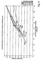
- Figure 4 shows a graph of engine torque supercharger boost against driver throttle angle demand between 0° and 90°.
- the diagonal straight lines on the graph are labelled with engine speed in rpm, between 1250 rpm and 5400 rpm.
- the vertical scale corresponds between the difference in engine torque in Figure 3 between the boosted torque curve 34 and the un-boosted torque curve 30.
- the engine torque supercharger boost is the maximum value shown in Figure 3.
- throttle angle demands declines from 90°, so does the engine torque supercharger boost, until this declines to zero boost corresponding to curve 30 of Figure 3.
- Figure 5 shows the operation of the supercharger in another way, with compressor demand plotted against driver "throttle angle” demand between 0° and 90°. Except at high engine speeds when operation of the supercharger is disabled, the driver "throttle angle” does not correspond with the actual angle of the throttle 17. At engine speeds where supercharger operation is permitted, the actual throttle angle will reach 90° (i.e. the maximum setting) before the driver "throttle angle” reaches 90°. Thereafter, as driver throttle angle increases towards 90°, the actual throttle angle remains at the maximum setting, and the boosted engine torque output is controlled by the amount of electrical power supplied to the supercharger motor, in conjunction with an appropriate amount of fuel delivered to the cylinders.
- the various lines in Figure 5 are labelled with the engine speed in rpm.
- the compressor demand is equivalent to the electrical power supplied to the supercharger motor 14.
- the plots begin at a compressor demand at about 0.2, at which point the air supplied by the supercharger begins to have an appreciable effect on engine torque.
- Figures 6 to 14 all show detailed views of the air intake apparatus according to the invention.
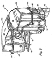
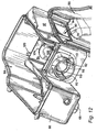
- Figure 6 shows an external perspective view of the unitary housing 50 that holds the battery 16, filter 9, compressor 10 and air bypass 12.
- the air supply path 3 through the unitary housing 50 begins at an air inlet 52 in a lower portion of the housing 50, and terminates at an air outlet 54 at a higher level in the housing 50.
- the housing 50 includes the battery compartment 56 and the supercharger compartment 58.
- Each compartment 56,58 has a corresponding access panel 60,62 which is removably attached by screws 64 to a unitary housing base 66 that forms a lower part of the enclosure 50.
- the battery compartment access panel 60 has a pair of apertures 61,63, by which a pair of battery terminals 65,67 can protrude through the housing 50 when the battery access panel is affixed to the housing base 66.
- the unitary housing base 66 is mounted at a number of supports 68 extending downwards from the housing base 66 to a steel mounting plate 70, which is itself bolted to an inner surface of an engine compartment (not shown).
- the hollow enclosure 50 is formed from a moulded plastics material, for example ABS, or glass-filled nylon.
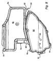
- Figure 7 shows the mounting plate, hollow enclosure 50 and a number of components inside the enclosure 50 in an exploded, perspective, view.
- the battery 16 is housed within the battery compartment 56, together with supercharger drive'electronics 72.
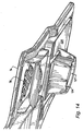
- the supercharger compartment 58 contains a larger number of components, including the filter 9, supercharger 10 and supercharger motor 14. Also in the supercharger compartment 58 are the dividing plate 74 that extends horizontally across a portion of the supercharger compartment 58 beneath the supercharger access cover 62, and the flap air bypass valve 13.
- the air filter 9 has a rectangular outline, and sits within a similar rectangular recess 56 within the dividing plate 74.
- the dividing plate 74 has an air grill 78 to the underside of which is attached the air flap 13, and a curved plate 80 to limit the deflection of the air flap 13 away from the grill 78.
- the supercharger compartment 58 is divided into a main portion 82, which houses the compressor 10, motor 14 and air filter 9, and a minor portion 84, which is referred to herein as a diffuser chamber 84.
- the dividing plate air grill 78, and air flap 13 lie over the diffuser chamber 74, with a flexible seal 86 making an air-tight seal between the diffuser chamber 84 and dividing plate 74.
- the air supply path 3 between the air inlet 52 and air outlet 54 extends around the battery 16 and supercharger power electronics 72 within the battery compartment 56, through an aperture 90 in a partition wall 92 that separates the battery compartment 56 from the supercharger compartment 58.
- the air aperture 90 is at a higher level in the battery compartment 56 from the air inlet 52. The air supply path through the battery compartment 56 therefore generally rises towards the air aperture 90.
- the air aperture 90 has a number of vanes, one of which 94 is visible in Figure 7. These vanes 94 direct the air flow into a lower portion of the supercharger compartment 58, in the vicinity of the supercharger motor 14. The air supply path therefore helps cool the supercharger motor 14 when this is operational.
- the air supply path 3 after flowing around the supercharger motor 14 rises vertically upwards through the air filter 9 in the dividing plate 74 into an air volume between the dividing plate 74 and supercharger access panel 62. In Figure 7, this enclosed air volume is indicated generally by reference numeral 96.
- the air suction provided from the inlet manifold 4 holds the flap valve 13 downwards onto the flap valve limiting plate 80, so that air can flow through the air grill 78 in the dividing plate 74, and into the diffuser chamber 84. From the diffuser chamber 84, the air is then free to pass into the air outlet 54. Although not shown, the air path then follows a conventional flexible hose to the throttle valve 17.
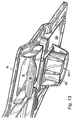
- the air expelled by the supercharger 10 through the diffuser chamber air inlet 104 passes into a diffuser pipe 106 that tapers gradually outwards to a diffuser pipe outlet 108.
- the diffuser pipe outlet 108 has three radial fins 110 equilaterally spaced around the circumference around the space of the diffuser pipe outlet 108.
- the fins 110 slot into corresponding grooves 112 on inner surfaces of the air outlet 54 so that an annular gap 114 is maintained between the air diffuser pipe 106 and air outlet 54.
- the air expelled by the supercharger 110 is therefore kept separate from air entering through the flap valve 13 into the diffuser chamber 84 until this air mixes downstream of the annular gap 114 surrounding the diffuser pipe outlet 108.
- the supercharger 10 and its motor 14 are physically mounted through three rubber posts 116 spaced equidistantly around a cup-shaped aluminium mounting bracket 118 to which the supercharger 10 has been rigidly mounted.
- the three rubber mounts 116 sit on three corresponding posts 120 extending upwards from a lower portion of the supercharger compartment 58.
- These three rubber mounts 116 together with the flexible short outlet hose 102 between the supercharger outlet 100 and diffuser chain inlet 104, dampen down any vibration which might be transmitted from the supercharger 10 and its motor 14 through to the body of the unitary housing 66.
- the supercharger 10 is also vibrationally isolated from the dividing plate 74 by a rubber ring 122 that extends around the circumference of the supercharger air inlet 98.
- the rubber ring 122 sits within a circular boss 124 that extends downwards from an undersurface 126 of the dividing plate 74.
- the boss 124 has a passage 127 therethrough to allow air to flow through the dividing plate 74 into the supercharger 10.
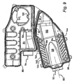
- FIGS 9 and 10 show how the air inlet path 3 extends into the battery compartment 56 initially in a recess 128 in a lower surface 156 of the battery compartment 56.
- the recess 128 gradually disappears downstream of the air inlet 52, thereby forcing inlet air to move laterally away from an axis 130 of the air inlet 52 towards lateral side portions 132 of the battery compartment 56, where there are a number of upstanding ribs 134 projecting from the side portions 132.
- the ribs 134 support an undersurface 136 of the battery 16, so that air channels 138 extend between the ribs 134 laterally away from the air inlet axis 130. Inlet air is therefore directed across nearly the full undersurface of the battery, which helps to keep the battery cool.
- the air is directed to flow upwards over corresponding vertically extending sides 142 of the battery 16 by vertically extending ribs 144 that project laterally inwards from the battery housing vertical side walls 140.
- the vertical ribs 144 also help to locate the battery 16 transversely within the battery compartment 56.
- the temperature of the inlet air therefore increases as it passes through the battery compartment 56, but the air is still cool compared with the temperatures that may be reached by the supercharger motor 14 (and significantly cooler than the air temperatures that would be encountered in a turbocharged or positive displacement supercharger system). This therefore provides an efficient means of cooling the various components within the housing 50.
- the air intake arrangement described above is both compact and economical to manufacture, and is suitable for use with relatively low capacity motor vehicle internal combustion engines.
Abstract
Description
- The present invention relates to an air intake apparatus for a motor vehicle.
- Motor vehicle batteries are usually mounted freely within an engine compartment. Such a position exposes the battery to extremes of cold in the winter, and to heat radiated or convected from the engine in the summer.
- It is therefore known to provide around the battery thermal insulation, however, this can have the effect of trapping in heat generated by the battery itself when supplying current.
- Document US-A-5 542 489 shows a battery being located in a battery housing and the housing having an air inlet and outlet.
- In some applications, notably, supplying current to an electrically powered supercharger, the current to be supplied by the battery can be very large, of the order of 150 amps at 12 volts. In this situation, it becomes even more important to control the battery temperature, as a cold battery will not supply as much current as a warm battery and a hot battery can become dangerously hot.
- It is an object of the present invention to address these issues.
- According to the invention, there is provided an air intake apparatus for an internal combustion engine, comprising a hollow unitary enclosure, a motor vehicle battery, the battery being housed within the enclosure, an engine air supply path through the enclosure, an air compressor for assisting airflow along the air supply path to the engine, the compressor having an air inlet and being housed within the enclosure, an air inlet to the enclosure and an air outlet from the enclosure, said enclosure inlet and enclosure outlet defining respectively an upstream end of the air supply path and a downstream end of the air supply path, the enclosure being partly divided by a partition into a battery compartment and a compressor compartment, the partition have an air passage therethrough and the battery being in the air path upstream of the partition, and the compressor forming at least a part of the air path downstream from the partition, wherein the air inlet is at a lower level than the air passage through the partition, and the air passage through the partition is at a lower level than the air inlet to the compressor.
- The use of a single enclosure for the battery, air compressor, air filter and bypass provides manufacturing economies, particularly if the enclosure is formed predominantly from plastics materials.
- The enclosure may be unitary in the sense that it forms a single unit around components within the enclosure, and is not formed form separate units, for example connected together by flexible hoses. The enclosure preferably has a main housing that is integrally formed, with the access panels being removably affixed to the main housing. In a preferred embodiment of the invention, the main housing forms a base portion of the hollow enclosure, and the access panels form an upper portion of the hollow enclosure.
- Since the temperature of the air will generally rise as it passes along the air supply path, this arrangement helps to increase the efficiency of the air flow. In addition, since the battery will generally be cooler than the compressor, or any other electronics downstream of the battery, the cooling efficiency is maximised by this arrangement, since generally cooler items are cooled first.
- The air supply path preferably extends between one or more external surfaces of the battery and one or more internal surfaces of the hollow enclosure including a lower surface of the battery and an internal surface of the hollow enclosure opposite the lower surface of the battery.
- In a preferred embodiment of the invention, the air inlet is entirely below the lower surface of the battery. The air supply path downstream of the battery may be entirely above the level of the battery lower surface.
- If at least one solid state electronic device is provided within the enclosure, the solid state device may be positioned within the air supply path downstream of the battery and at a level extending above the level of the battery lower surface, so that air flow along the air supply path cools the solid state device when in said device is in use.
- The internal surface of the hollow enclosure opposite the lower surface of the battery may have projecting ribs that support the weight of the battery, said ribs having air channels therebetween to direct the flow of air along the air supply path beneath the battery.
- Preferably, the supply path extends between one or more external vertically extending surfaces of the battery and one or more vertically extending internal surfaces of the hollow enclosure opposite the lower surface of the battery. These vertically extending internal surfaces of the hollow enclosure may have projecting ribs that help locate the battery within the enclosure, and these ribs can then have ribs having air channels therebetween to direct the flow of air upwards along said vertically extending surfaces of the battery.
- In a preferred embodiment of the invention the apparatus includes an air filter, with the air filter extending across the air supply path at a level no higher than the level of the compressor air inlet.
- The invention will now be described by way of example, with reference to the accompanying drawings, in which:
- Figure 1 is a schematic diagram of a motor vehicle having a 1.4 litre, four cylinder engine system with an air intake apparatus that includes an electrically powered intake compressor, according to the invention;
- Figure 2 is a graph plotting engine torque against engine speed for the 1.4 litre engine of Figure 1 when naturally aspirated, tuned either for maximum torque at a low moderate engine speed, or maximum engine torque at a higher moderate engine speed;
- Figure 3 is a graph similar to that of Figure 2, showing also the effect on engine torque output with the engine of Figure 1 when using the intake compressor;
- Figure 4 is a graph plotting engine compressor torque boost against driver throttle engine demand for the engine of Figure 1;
- Figure 5 is a graph of compressor demand against driver throttle angle demand for the engine of Figure 1;
- Figure 6 is a perspective view of the air intake apparatus used with the engine of Figure 1;
- Figure 7 is an exploded view of a housing and internal components that form the air intake apparatus of Figure 6;
- Figure 8 is a top plan view of the air intake apparatus of Figure 7, showing two separate removable access panels on upper surfaces of the housing;
- Figure 9 is a top plan view of the air intake apparatus similar to that of Figure 8, but with the two access panels removed, and no components within the housing;
- Figure 10 is a perspective view of the empty housing of Figure 9;
- Figure 11 is a perspective view of a portion of the housing, with an access panel removed to show the compressor within the housing, and an air outlet pipe from the compressor extending through an air diffuser chamber to an air outlet from the housing;
- Figure 12 is a different perspective view of the portion of the housing shown in Figure 11, looking into the air outlet to show the arrangement of the air outlet pipe with respect to the air outlet and the diffuser chamber;
- Figure 13 is a perspective view from underneath of a portion of a dividing plate that covers the air compressor and air diffuser chamber of Figures 11 and 12, showing an air flap valve in the diffuser plate in a closed position; and
- Figure 14 is a perspective view similar to that of Figure 13, with the air flap valve removed to show an air grille through the dividing plate by which bypass air flows into the diffuser chamber to the housing air outlet.
-
- Figure 1 shows schematically part of a
motor vehicle 7 having a supercharged reciprocating pistoninternal combustion engine 1, with four in-line cylinders 2, an air inlet manifold 4 and an exhaust manifold 6 leading to and from each of thecylinders 2, and afuel injection system 8 for supplying fuel tocylinders 2 in a manner well-known in the art. A compressor, here an electrically drivensupercharger 10, is provided upstream of the inlet manifold 4. - Air flows to the inlet manifold 4 through the
supercharger 10 when this is operational, or when the supercharger is disabled, through an air bypass conduit 12 in parallel with thesupercharger 10. Air is supplied to thesupercharger 10 and/or thebypass 12 along aninlet air path 3. - The
air bypass conduit 12 has anair valve 13 that automatically opens to permitinlet air 5 to bypass the supercharger when thesupercharger airflow 15 is insufficient to charge theengine cylinders 2 with air. The air supply to theengine 1 is then controlled by the setting of athrottle valve 17 downstream of thesupercharger 10 andbypass 12, and the activation of thesupercharger 10. When thesupercharger 10 is not activated, theengine 1 is normally aspirated, and when thesupercharger 10 is activated, the airflow to the engine is increased. - The supercharger is driven only by a switched reluctance electrical motor (M) 14 powered by a 12-volt lead/
acid vehicle battery 16 and a belt-driven alternator (not shown). The battery has a current rating which is about 30 A higher than would normally be specified for a mass-market four cylinder engine motor car. In addition to powering the supercharger, thebattery 16 also provides for the vehicle starting, lighting and ignition requirements. As indicated by Figure 1, thebattery 16 also lies within theair supply path 3, so that inlet air flows around thebattery 16. - An air filter 9 is provided in the
air supply path 3 downstream of thebattery 16 and upstream of thesupercharger 10 andair bypass 12. - As will be explained in more detail below, the
battery 16, filter 9, supercharger 10 andair bypass 12 are all housed within ahollow enclosure 50. - The vehicle driver (not shown) can control the engine power via a movable
accelerator pedal assembly 18, that provides anelectrical signal 20 to an engine control unit (ECU) 22. The engine control unit receives a number of input signals indicative of engine and vehicle operating parameters, including anengine speed signal 24 from anengine speed sensor 26. Theengine control unit 22 calculates an engine torque demand from the various input signals, and provides a number of output signals to control various vehicle and engine operating parameters, including a fuelinjection control signal 28, throttlevalve control signal 30 and a superchargermotor control signal 32. The engine torque demand is therefore set at least in part by the position of the accelerator pedal. - As will be explained in more detail below, when the driver moves the accelerator pedal to demand engine torque in excess of that which can be delivered by the
engine 1 when naturally aspirated, thethrottle valve 17 moves to a maximum setting to admit the maximum volume of air into the cylinders, andengine control unit 22 then activates thesupercharger motor 14 under certain moderate or low engine speeds, but not at high engine speeds. Thereafter, the boosted engine torque output is controlled by the supercharger speed and the amount of fuel supplied to the cylinders. If the engine is an injection engine, theengine control unit 22 can control the amount of injected fuel by electrical control of the injectors. - Preferably, the engine includes an exhaust gas sensor 31 for monitoring engine combustion conditions. The sensor 31 may be an exhaust gas oxygen (EGO) sensor. This can be sued to determine if the engine is running lean or rich. The
engine control unit 22 first sets both the supercharger speed and delivered fuel amount according to the current torque demand. The engine control unit monitors the output from the sensor 31, and then adjusts the supercharger speed and/or the amount of delivered fuel to achieve an appropriate level of rich or lean engine operation. - Figure 2 shows a graph of engine torque against engine speed for a conventional four-cylinder in-line engine, such as that described above, but without supercharging. As can be seen from
curve 30 of Figure 2, the engine can be tuned to provide good power at moderately high engine speeds ("power tune"), but at the expense of low-end torque. - Alternatively, as shown by
curve 32, the engine can be tuned to give good torque at low and moderate engine speeds ("torque tune"), but at the expense of top-end torque. Whilst "power tune" will appeal to the 'sporting' driver, it will result in lower levels of satisfaction for the majority of car owners. The requirement to deliver good real world 'performance feel' commonly results in an engine torque output as shown in the "torque tune" curve, where torque at high engine speeds has been compromised in order to promote torque output below 3500 rpm. Although engine gearing can be selected to minimize undesirable characteristics, in practice conventional engines are tuned to achieve a compromise. - With reference to Figure 3, in the preferred embodiment of the invention, a relatively low capacity engine, for example below about 1.8 litres capacity, is tuned to give good power at high rpm, at the expense of torque at low engine speed, as illustrated by
curve 30. This has the secondary effect of allowing good fuel economy at steady highway cruising speeds through the need to use wider throttle openings to achieve cruising speed. As can be seen fromcurve 34, an increase in maximum engine torque is then provided with a supercharger torque boost (or equivalently engine power boost) when the driver demands power in excess of that available from a naturally aspirated engine, as shown by the curve with supercharger boost "SCB". The boost is made available under control of theengine control unit 22 only in a region of low 38 and moderate engine speeds 33, and is progressively limited to transition smoothly into engine power atpoint 35 without compressor torque boost in a region of higher engine speeds 37. This is done by progressively limiting the maximum allowable supercharger boost proximate atransition point 40, which in this example is taken at the maximum un-boosted engine torque. It is, however, possible to deviate either above or below this point, although a deviation too far below this point (in this example below about 3500 rpm) reduces the potential benefits provided by the supercharger, and a deviation too far above this point (in this example above about 5750 rpm) will lead to excess torque in a region of engine operation where this is not needed under most driving conditions, or desired from the point of view of fuel economy. - Thus, the engine controller enables use of the compressor driver only in such a way that the engine torque output with the compressor torque boost peaks in the region of moderate engine speed.
- The boosted torque curve could, however, transition smoothly into the
un-boosted torque curve 30 in a region of lower engine speeds 38, as shown by dashedline 39. - Figure 4 shows a graph of engine torque supercharger boost against driver throttle angle demand between 0° and 90°. The diagonal straight lines on the graph are labelled with engine speed in rpm, between 1250 rpm and 5400 rpm. The vertical scale corresponds between the difference in engine torque in Figure 3 between the boosted
torque curve 34 and theun-boosted torque curve 30. At themaximum throttle angle 90°, the engine torque supercharger boost is the maximum value shown in Figure 3. As throttle angle demands declines from 90°, so does the engine torque supercharger boost, until this declines to zero boost corresponding tocurve 30 of Figure 3. - As can be seen from Figure 4, as the engine speed increases towards the
transition point 35 of Figure 3, the slope of the engine torque supercharger boost curve declines, until at thetransition point 35, there is no engine torque supercharger boost. This shows graphically the progressive disabling of the supercharger boost. - Figure 5 shows the operation of the supercharger in another way, with compressor demand plotted against driver "throttle angle" demand between 0° and 90°. Except at high engine speeds when operation of the supercharger is disabled, the driver "throttle angle" does not correspond with the actual angle of the
throttle 17. At engine speeds where supercharger operation is permitted, the actual throttle angle will reach 90° (i.e. the maximum setting) before the driver "throttle angle" reaches 90°. Thereafter, as driver throttle angle increases towards 90°, the actual throttle angle remains at the maximum setting, and the boosted engine torque output is controlled by the amount of electrical power supplied to the supercharger motor, in conjunction with an appropriate amount of fuel delivered to the cylinders. - The various lines in Figure 5 are labelled with the engine speed in rpm. The compressor demand is equivalent to the electrical power supplied to the
supercharger motor 14. The plots begin at a compressor demand at about 0.2, at which point the air supplied by the supercharger begins to have an appreciable effect on engine torque. As can be seen from Figure 5, as engine speed increases, so does the minimum compressor demand needed to appreciably boost torque. This is due to the increased air flow to the inlet manifold 4 as engine speed increases. - Figures 6 to 14 all show detailed views of the air intake apparatus according to the invention. Figure 6 shows an external perspective view of the
unitary housing 50 that holds thebattery 16, filter 9,compressor 10 andair bypass 12. Theair supply path 3 through theunitary housing 50 begins at anair inlet 52 in a lower portion of thehousing 50, and terminates at anair outlet 54 at a higher level in thehousing 50. - The
housing 50 includes thebattery compartment 56 and thesupercharger compartment 58. Eachcompartment corresponding access panel screws 64 to aunitary housing base 66 that forms a lower part of theenclosure 50. - The battery
compartment access panel 60 has a pair ofapertures battery terminals housing 50 when the battery access panel is affixed to thehousing base 66. - The
unitary housing base 66 is mounted at a number ofsupports 68 extending downwards from thehousing base 66 to asteel mounting plate 70, which is itself bolted to an inner surface of an engine compartment (not shown). - The
hollow enclosure 50 is formed from a moulded plastics material, for example ABS, or glass-filled nylon. - Figure 7 shows the mounting plate,
hollow enclosure 50 and a number of components inside theenclosure 50 in an exploded, perspective, view. Thebattery 16 is housed within thebattery compartment 56, together withsupercharger drive'electronics 72. - The
supercharger compartment 58 contains a larger number of components, including the filter 9,supercharger 10 andsupercharger motor 14. Also in thesupercharger compartment 58 are the dividingplate 74 that extends horizontally across a portion of thesupercharger compartment 58 beneath thesupercharger access cover 62, and the flapair bypass valve 13. The air filter 9 has a rectangular outline, and sits within a similarrectangular recess 56 within the dividingplate 74. The dividingplate 74 has anair grill 78 to the underside of which is attached theair flap 13, and acurved plate 80 to limit the deflection of theair flap 13 away from thegrill 78. - The
supercharger compartment 58 is divided into amain portion 82, which houses thecompressor 10,motor 14 and air filter 9, and aminor portion 84, which is referred to herein as adiffuser chamber 84. The dividingplate air grill 78, andair flap 13 lie over thediffuser chamber 74, with aflexible seal 86 making an air-tight seal between thediffuser chamber 84 and dividingplate 74. - The
air supply path 3 between theair inlet 52 andair outlet 54 extends around thebattery 16 andsupercharger power electronics 72 within thebattery compartment 56, through anaperture 90 in apartition wall 92 that separates thebattery compartment 56 from thesupercharger compartment 58. As can be seen from Figure 7, theair aperture 90 is at a higher level in thebattery compartment 56 from theair inlet 52. The air supply path through thebattery compartment 56 therefore generally rises towards theair aperture 90. - The
air aperture 90 has a number of vanes, one of which 94 is visible in Figure 7. Thesevanes 94 direct the air flow into a lower portion of thesupercharger compartment 58, in the vicinity of thesupercharger motor 14. The air supply path therefore helps cool thesupercharger motor 14 when this is operational. Theair supply path 3 after flowing around thesupercharger motor 14 rises vertically upwards through the air filter 9 in the dividingplate 74 into an air volume between the dividingplate 74 andsupercharger access panel 62. In Figure 7, this enclosed air volume is indicated generally byreference numeral 96. - When the supercharger is not operational, the air suction provided from the inlet manifold 4 holds the
flap valve 13 downwards onto the flapvalve limiting plate 80, so that air can flow through theair grill 78 in the dividingplate 74, and into thediffuser chamber 84. From thediffuser chamber 84, the air is then free to pass into theair outlet 54. Although not shown, the air path then follows a conventional flexible hose to thethrottle valve 17. - When the supercharger is operational, some air from the
enclosed air volume 96 will be drawn into aninlet 98 in an upper central portion of thesupercharger 10. The supercharger air is then compressed and expelled at up to 40% above atmospheric pressure through thesupercharger outlet 100. Asmall rubber ring 102 connects thesupercharger air outlet 100 to aninlet 104 to thediffuser chamber 84. - Until the
supercharger 10 is operating at a high capacity, there will be some air also entering through theair flap 13 into thediffuser chamber 84. The air expelled by thesupercharger 10 through the diffuserchamber air inlet 104 passes into adiffuser pipe 106 that tapers gradually outwards to adiffuser pipe outlet 108. Thediffuser pipe outlet 108 has threeradial fins 110 equilaterally spaced around the circumference around the space of thediffuser pipe outlet 108. Thefins 110 slot into correspondinggrooves 112 on inner surfaces of theair outlet 54 so that anannular gap 114 is maintained between theair diffuser pipe 106 andair outlet 54. - The air expelled by the
supercharger 110 is therefore kept separate from air entering through theflap valve 13 into thediffuser chamber 84 until this air mixes downstream of theannular gap 114 surrounding thediffuser pipe outlet 108. - It has been found that the air flow efficiency is increased by this arrangement, as energy in the air expelled by the
supercharger 10 helps to pull air out of thediffuser chamber 84 supplied through theair flap valve 13. - In order to dampen noise and vibration, the
supercharger 10 and itsmotor 14 are physically mounted through threerubber posts 116 spaced equidistantly around a cup-shapedaluminium mounting bracket 118 to which thesupercharger 10 has been rigidly mounted. The three rubber mounts 116 sit on threecorresponding posts 120 extending upwards from a lower portion of thesupercharger compartment 58. These three rubber mounts 116, together with the flexibleshort outlet hose 102 between thesupercharger outlet 100 anddiffuser chain inlet 104, dampen down any vibration which might be transmitted from thesupercharger 10 and itsmotor 14 through to the body of theunitary housing 66. - The
supercharger 10 is also vibrationally isolated from the dividingplate 74 by a rubber ring 122 that extends around the circumference of thesupercharger air inlet 98. The rubber ring 122 sits within acircular boss 124 that extends downwards from anundersurface 126 of the dividingplate 74. Theboss 124 has apassage 127 therethrough to allow air to flow through the dividingplate 74 into thesupercharger 10. - Referring now to Figures 9 and 10, these show how the
air inlet path 3 extends into thebattery compartment 56 initially in arecess 128 in alower surface 156 of thebattery compartment 56. Therecess 128 gradually disappears downstream of theair inlet 52, thereby forcing inlet air to move laterally away from anaxis 130 of theair inlet 52 towardslateral side portions 132 of thebattery compartment 56, where there are a number ofupstanding ribs 134 projecting from theside portions 132. Theribs 134 support anundersurface 136 of thebattery 16, so thatair channels 138 extend between theribs 134 laterally away from theair inlet axis 130. Inlet air is therefore directed across nearly the full undersurface of the battery, which helps to keep the battery cool. Once the inlet air reacheslateral side walls 140 of thebattery compartment 56, the air is directed to flow upwards over corresponding vertically extendingsides 142 of thebattery 16 by vertically extendingribs 144 that project laterally inwards from the battery housingvertical side walls 140. Thevertical ribs 144 also help to locate thebattery 16 transversely within thebattery compartment 56. - Some air will, however, flow downstream of the
battery 16 at a lower level to encounter thesupercharger power electronics 72, which is provided with metallicheat dissipation fins 146. - The temperature of the inlet air therefore increases as it passes through the
battery compartment 56, but the air is still cool compared with the temperatures that may be reached by the supercharger motor 14 (and significantly cooler than the air temperatures that would be encountered in a turbocharged or positive displacement supercharger system). This therefore provides an efficient means of cooling the various components within thehousing 50. - The air intake arrangement described above is both compact and economical to manufacture, and is suitable for use with relatively low capacity motor vehicle internal combustion engines.
Claims (9)
- An air intake apparatus for an internal combustion engine (1), comprising a hollow enclosure (50), a motor vehicle battery (16), the battery being housed within the enclosure (50), an engine air supply path (3) through the enclosure (50), an air compressor (10) for assisting airflow along the air supply path (3) to the engine (1), the compressor (10) having an air inlet (98) and being housed within the enclosure (50), an air inlet (52) to the enclosure and an air outlet (54) from the enclosure, said enclosure inlet (52) and enclosure outlet (54) defining respectively an upstream end of the air supply path (3) and a downstream end of the air supply path (3), the enclosure (50) being partly divided by a partition (92) into a battery compartment (56) and a compressor compartment (58), the partition (92) have an air passage (90) therethrough and the battery (16) being in the air path (3) upstream of the partition (92), and the compressor (10) forming at least a part of the air path (3) downstream from the partition (92), wherein the air inlet (52) is at a lower level than the air passage (90) through the partition (92), and the air passage (90) through the partition (92) is at a lower level than the air inlet (98) to the compressor (10).
- An air intake apparatus as claimed in Claim 1, in which, the air supply path (3) extends between one or more external surfaces (136,142) of the battery (16) and one or more internal surfaces (128,140,156) of the enclosure (50) including a lower surface (136) of the battery (16) and an internal surface (128,156) of the enclosure (50) opposite the lower surface (136) of the battery (16).
- An air intake apparatus as claimed in Claim 2, in which the air inlet (52) is entirely below the lower surface (136) of the battery (16).
- An air intake apparatus as claimed in any preceding claim, in which the air supply path (3) downstream of the battery (16) is above the level of the battery lower surface (136).
- An air intake apparatus as claimed in any preceding claim, including at least one solid state electronic device (72) within the enclosure (50), in which the solid state device (72) is positioned within the air supply path (3) downstream of the battery (16) and at a level extending above the level of the battery lower surface (136), so that air flow along the air supply path (3) cools the solid state device (72) when in said device is in use.
- An air intake apparatus as claimed in any preceding claim, in which the internal surface (128,156) of the enclosure (50) opposite the lower surface (136) of the battery (16) has projecting ribs (134) that support the weight of the battery (16), said ribs (134) having air channels (138) therebetween to direct the flow of air along the air supply path (3) beneath the battery (16).
- An air intake apparatus as claimed in any preceding claim, in which the air supply path (3) extends between one or more external vertically extending surfaces (142) of the battery (16) and one or more vertically extending internal surfaces (140) of the enclosure (50) opposite the lower surface of the battery (16), said vertically extending internal surfaces (140) of the enclosure (50) having projecting ribs (144) that help locate the battery (16) within the enclosure (50), said ribs (144) having air channels therebetween to direct the flow of air upwards along said vertically extending surfaces (142) of the battery (16).
- An air intake apparatus as claimed in any preceding claim, in which the apparatus includes an air filter (9), the air filter extending across the air supply path (3) at a level no higher than the level of the compressor air inlet (98).
- A motor vehicle, comprising an internal combustion engine (1), and an air intake apparatus, wherein the air intake apparatus is as claimed in any preceding claim.
Applications Claiming Priority (5)
| Application Number | Priority Date | Filing Date | Title |
|---|---|---|---|
| GB0018428 | 2000-07-28 | ||
| GB0018428A GB2365065A (en) | 2000-07-28 | 2000-07-28 | Supercharging i.c. engines |
| GB0023773 | 2000-09-28 | ||
| GB0023773A GB2364977A (en) | 2000-07-28 | 2000-09-28 | A combined air intake, air compressor and battery housing for an internal combustion engine |
| PCT/GB2001/003408 WO2002010580A1 (en) | 2000-07-28 | 2001-07-26 | An air intake arrangement for an internal combustion engine |
Publications (2)
| Publication Number | Publication Date |
|---|---|
| EP1305515A1 EP1305515A1 (en) | 2003-05-02 |
| EP1305515B1 true EP1305515B1 (en) | 2004-06-16 |
Family
ID=26244738
Family Applications (1)
| Application Number | Title | Priority Date | Filing Date |
|---|---|---|---|
| EP01951829A Expired - Lifetime EP1305515B1 (en) | 2000-07-28 | 2001-07-26 | An air intake arrangement for an internal combustion engine |
Country Status (6)
| Country | Link |
|---|---|
| US (1) | US6892713B2 (en) |
| EP (1) | EP1305515B1 (en) |
| JP (1) | JP3779270B2 (en) |
| AU (1) | AU2001272678A1 (en) |
| DE (1) | DE60103900T2 (en) |
| WO (1) | WO2002010580A1 (en) |
Families Citing this family (19)
| Publication number | Priority date | Publication date | Assignee | Title |
|---|---|---|---|---|
| EP1038346A2 (en) * | 1997-10-21 | 2000-09-27 | Stridsberg Innovation Ab | A hybrid powertrain |
| EP1300560B1 (en) * | 2001-10-03 | 2005-08-31 | Visteon Global Technologies, Inc. | Control system for an internal combustion engine boosted with an electronically controlled pressure charging device |
| EP1357275A1 (en) | 2002-04-26 | 2003-10-29 | Visteon Global Technologies, Inc. | Modelling of the thermal behaviour of a switched reluctance motor driving a supercharger of an internal combustion engine |
| US6769411B2 (en) * | 2002-09-23 | 2004-08-03 | Sandor C. Fabiani | Nozzle air injection system for a fuel-injected engine |
| US7025159B2 (en) * | 2003-09-12 | 2006-04-11 | Ford Global Technologies, Llc | Cooling system for a vehicle battery |
| US7347883B2 (en) * | 2004-03-24 | 2008-03-25 | Advanced Flow Engineering, Inc. | High flow air filtration system for ford truck |
| JP4371036B2 (en) * | 2004-10-20 | 2009-11-25 | 日産自動車株式会社 | Hybrid vehicle inverter buffer structure |
| JP4516502B2 (en) * | 2005-08-31 | 2010-08-04 | 本田技研工業株式会社 | Battery arrangement structure for rough terrain vehicle |
| EP1897739B1 (en) * | 2006-09-07 | 2010-11-03 | Honda Motor Co., Ltd. | Electrical device cooling structure in vehicle |
| US7918296B2 (en) * | 2008-09-15 | 2011-04-05 | Caterpillar Inc. | Cooling system for an electric drive machine and method |
| US20100283262A1 (en) * | 2009-05-11 | 2010-11-11 | Caterpillar Inc. | Energy Recovery And Cooling System For A Hybrid Machine |
| US8677966B2 (en) | 2011-01-20 | 2014-03-25 | Advanced Flow Engineering, Inc. | Air intake flow device and system |
| US8955630B2 (en) * | 2011-12-14 | 2015-02-17 | Honda Motor Co., Ltd. | Symbiotic engine intake system and battery box |
| DE102013113060B4 (en) * | 2013-11-26 | 2017-03-16 | Pierburg Gmbh | Fuel gas supply system for an internal combustion engine |
| US9583801B2 (en) | 2014-06-25 | 2017-02-28 | Honda Motor Co., Ltd. | Battery temperature regulating system |
| DE102014212898A1 (en) * | 2014-07-03 | 2016-01-07 | Robert Bosch Gmbh | Method for determining an emergency trajectory and method for partially automated or automated guidance of an ego vehicle |
| FR3072335B1 (en) | 2017-10-12 | 2020-08-28 | Psa Automobiles Sa | VEHICLE INCLUDING A BATTERY HOUSED IN A COLD BOX |
| FR3110940B1 (en) * | 2020-05-27 | 2022-07-29 | Renault Sas | Air intake circuit cooling a battery. |
| DE102020130786B3 (en) * | 2020-11-20 | 2021-11-25 | Dr. Ing. H.C. F. Porsche Aktiengesellschaft | Hybrid vehicle |
Family Cites Families (26)
| Publication number | Priority date | Publication date | Assignee | Title |
|---|---|---|---|---|
| US4285309A (en) * | 1979-11-13 | 1981-08-25 | Jonsereds Aktiebolag | Housing for an internal combustion engine |
| FR2488330A1 (en) | 1980-08-11 | 1982-02-12 | Chauvierre Marc | Electric motor for low speed supercharging of IC engine - is driven until speed has risen sufficiently for exhaust turbine to be effective, and is controlled by throttle position and engine speed |
| US4469078A (en) * | 1981-04-27 | 1984-09-04 | Speer Stephen R | Aircraft engine-turbocharger package with bleed valve control |
| DE3205721A1 (en) | 1982-02-18 | 1983-08-25 | Volkswagenwerk Ag, 3180 Wolfsburg | Supercharged internal combustion engine for vehicles |
| JPS5918227A (en) | 1982-07-22 | 1984-01-30 | Aisin Seiki Co Ltd | Controlling method of supercharger for automobile engine |
| GB2155542A (en) | 1984-03-06 | 1985-09-25 | Austin Rover Group | I.C. Engine supercharger driven via a variable ratio transmission |
| JPS6251729A (en) | 1985-08-30 | 1987-03-06 | Isuzu Motors Ltd | Turbocharger control device for internal combustion engine |
| US4730457A (en) | 1985-10-29 | 1988-03-15 | Fuji Jukogyo Kabushiki Kaisha | Supercharging system for automotive engines |
| DE3618449A1 (en) | 1986-05-31 | 1987-12-03 | Erich Dr Mont Zimmermann | Turbocharger with electrical auxiliary drive |
| JPH01100319A (en) * | 1987-10-14 | 1989-04-18 | Sanden Corp | Mechanical supercharger |
| US4976327A (en) * | 1989-02-14 | 1990-12-11 | Globe-Union Inc. | Battery module for the engine compartment of an automobile |
| US5031712A (en) * | 1989-09-07 | 1991-07-16 | Globe-Union, Inc. | Method and apparatus for thermal control of automotive components |
| US5082075A (en) * | 1989-09-07 | 1992-01-21 | Globe-Union Inc. | Method and apparatus for thermal control of automotive components |
| DE4102414A1 (en) | 1991-01-28 | 1992-07-30 | Peter Tontch | Increasing charge power of IC engine turbocharger - activating electromotor via control to accelerate charge shaft and increase engine torque at low engine RPM |
| FR2677933B1 (en) * | 1991-06-20 | 1996-05-31 | Giat Ind Sa | METHOD AND DEVICE FOR COOLING BATTERIES IN A VEHICLE EQUIPPED WITH A HEAT ENGINE. |
| US5636701A (en) * | 1994-07-29 | 1997-06-10 | Chrysler Corporation | Battery tray assembly |
| US5542489A (en) * | 1995-05-31 | 1996-08-06 | Ford Motor Company | Battery thermal chamber |
| US6029452A (en) | 1995-11-15 | 2000-02-29 | Turbodyne Systems, Inc. | Charge air systems for four-cycle internal combustion engines |
| JPH10317980A (en) * | 1997-05-16 | 1998-12-02 | Ishikawajima Harima Heavy Ind Co Ltd | Automobile screw type supercharger |
| FR2764944A1 (en) * | 1997-06-18 | 1998-12-24 | Alexis Defarge | Carburation device giving control of mixture and flow into cylinders of IC engines |
| FR2774130B1 (en) * | 1998-01-23 | 2000-03-10 | Renault | INTERNAL COMBUSTION ENGINE HAVING A COMPACT AIR INTAKE CIRCUIT |
| US6167976B1 (en) * | 1998-07-30 | 2001-01-02 | Deere & Company | Engine enclosure |
| US6230833B1 (en) * | 1999-07-06 | 2001-05-15 | Visteon Global Technologies, Inc. | Storage battery tuning of engine air intake system |
| DE19952136A1 (en) * | 1999-10-29 | 2001-05-03 | Mann & Hummel Filter | Intake system |
| US20030047366A1 (en) * | 2001-07-10 | 2003-03-13 | Johnson Controls Technology Company | Module for battery and/or other vehicle components |
| JP3864100B2 (en) * | 2002-02-18 | 2006-12-27 | 日産自動車株式会社 | Intake device for internal combustion engine |
-
2001
- 2001-07-26 EP EP01951829A patent/EP1305515B1/en not_active Expired - Lifetime
- 2001-07-26 US US10/343,193 patent/US6892713B2/en not_active Expired - Lifetime
- 2001-07-26 WO PCT/GB2001/003408 patent/WO2002010580A1/en active IP Right Grant
- 2001-07-26 JP JP2002516475A patent/JP3779270B2/en not_active Expired - Fee Related
- 2001-07-26 DE DE60103900T patent/DE60103900T2/en not_active Expired - Fee Related
- 2001-07-26 AU AU2001272678A patent/AU2001272678A1/en not_active Abandoned
Also Published As
| Publication number | Publication date |
|---|---|
| US20040060754A1 (en) | 2004-04-01 |
| JP2004505201A (en) | 2004-02-19 |
| US6892713B2 (en) | 2005-05-17 |
| WO2002010580A1 (en) | 2002-02-07 |
| EP1305515A1 (en) | 2003-05-02 |
| JP3779270B2 (en) | 2006-05-24 |
| DE60103900T2 (en) | 2005-06-30 |
| DE60103900D1 (en) | 2004-07-22 |
| AU2001272678A1 (en) | 2002-02-13 |
Similar Documents
| Publication | Publication Date | Title |
|---|---|---|
| EP1305515B1 (en) | An air intake arrangement for an internal combustion engine | |
| EP1305519B1 (en) | An air intake arrangement for an internal combustion engine | |
| EP1305518B1 (en) | An air intake arrangement for an internal combustion engine | |
| EP1305517B1 (en) | An air intake arrangement for an internal combustion engine | |
| EP1305516B1 (en) | An air intake arrangement for an internal combustion engine | |
| EP1300559B1 (en) | Control system for an internal combustion engine boosted with an electronically controlled pressure charging device | |
| EP1305506B1 (en) | Internal combustion engine supercharger | |
| GB2364977A (en) | A combined air intake, air compressor and battery housing for an internal combustion engine | |
| EP1300570B1 (en) | Control system for an internal combustion engine boosted with an electronically controlled pressure charging device |
Legal Events
| Date | Code | Title | Description |
|---|---|---|---|
| PUAI | Public reference made under article 153(3) epc to a published international application that has entered the european phase |
Free format text: ORIGINAL CODE: 0009012 |
|
| 17P | Request for examination filed |
Effective date: 20021009 |
|
| AK | Designated contracting states |
Designated state(s): AT BE CH CY DE DK ES FI FR GB GR IE IT LI LU MC NL PT SE TR |
|
| AX | Request for extension of the european patent |
Extension state: AL LT LV MK RO SI |
|
| GRAP | Despatch of communication of intention to grant a patent |
Free format text: ORIGINAL CODE: EPIDOSNIGR1 |
|
| GRAS | Grant fee paid |
Free format text: ORIGINAL CODE: EPIDOSNIGR3 |
|
| GRAA | (expected) grant |
Free format text: ORIGINAL CODE: 0009210 |
|
| AK | Designated contracting states |
Kind code of ref document: B1 Designated state(s): DE FR GB |
|
| PG25 | Lapsed in a contracting state [announced via postgrant information from national office to epo] |
Ref country code: FR Free format text: LAPSE BECAUSE OF FAILURE TO SUBMIT A TRANSLATION OF THE DESCRIPTION OR TO PAY THE FEE WITHIN THE PRESCRIBED TIME-LIMIT Effective date: 20040616 |
|
| RBV | Designated contracting states (corrected) |
Designated state(s): DE FR GB |
|
| REG | Reference to a national code |
Ref country code: GB Ref legal event code: FG4D |
|
| PGFP | Annual fee paid to national office [announced via postgrant information from national office to epo] |
Ref country code: DE Payment date: 20040721 Year of fee payment: 4 Ref country code: FR Payment date: 20040721 Year of fee payment: 4 |
|
| REF | Corresponds to: |
Ref document number: 60103900 Country of ref document: DE Date of ref document: 20040722 Kind code of ref document: P |
|
| REG | Reference to a national code |
Ref country code: IE Ref legal event code: FG4D |
|
| LTIE | Lt: invalidation of european patent or patent extension |
Effective date: 20040616 |
|
| PLBE | No opposition filed within time limit |
Free format text: ORIGINAL CODE: 0009261 |
|
| STAA | Information on the status of an ep patent application or granted ep patent |
Free format text: STATUS: NO OPPOSITION FILED WITHIN TIME LIMIT |
|
| REG | Reference to a national code |
Ref country code: IE Ref legal event code: MM4A |
|
| 26N | No opposition filed |
Effective date: 20050317 |
|
| EN | Fr: translation not filed | ||
| PG25 | Lapsed in a contracting state [announced via postgrant information from national office to epo] |
Ref country code: DE Free format text: LAPSE BECAUSE OF NON-PAYMENT OF DUE FEES Effective date: 20060201 |
|
| REG | Reference to a national code |
Ref country code: GB Ref legal event code: 732E |
|
| REG | Reference to a national code |
Ref country code: GB Ref legal event code: 732E |
|
| PGFP | Annual fee paid to national office [announced via postgrant information from national office to epo] |
Ref country code: GB Payment date: 20170825 Year of fee payment: 17 |
|
| GBPC | Gb: european patent ceased through non-payment of renewal fee |
Effective date: 20180726 |
|
| PG25 | Lapsed in a contracting state [announced via postgrant information from national office to epo] |
Ref country code: GB Free format text: LAPSE BECAUSE OF NON-PAYMENT OF DUE FEES Effective date: 20180726 |