EP1306239A2 - Air supply unit for a vehicle - Google Patents
Air supply unit for a vehicle Download PDFInfo
- Publication number
- EP1306239A2 EP1306239A2 EP02018423A EP02018423A EP1306239A2 EP 1306239 A2 EP1306239 A2 EP 1306239A2 EP 02018423 A EP02018423 A EP 02018423A EP 02018423 A EP02018423 A EP 02018423A EP 1306239 A2 EP1306239 A2 EP 1306239A2
- Authority
- EP
- European Patent Office
- Prior art keywords
- supply unit
- air supply
- air
- hose
- unit according
- Prior art date
- Legal status (The legal status is an assumption and is not a legal conclusion. Google has not performed a legal analysis and makes no representation as to the accuracy of the status listed.)
- Granted
Links
Images

Classifications
-
- B—PERFORMING OPERATIONS; TRANSPORTING
- B60—VEHICLES IN GENERAL
- B60G—VEHICLE SUSPENSION ARRANGEMENTS
- B60G17/00—Resilient suspensions having means for adjusting the spring or vibration-damper characteristics, for regulating the distance between a supporting surface and a sprung part of vehicle or for locking suspension during use to meet varying vehicular or surface conditions, e.g. due to speed or load
- B60G17/02—Spring characteristics, e.g. mechanical springs and mechanical adjusting means
- B60G17/04—Spring characteristics, e.g. mechanical springs and mechanical adjusting means fluid spring characteristics
- B60G17/0408—Spring characteristics, e.g. mechanical springs and mechanical adjusting means fluid spring characteristics details, e.g. antifreeze for suspension fluid, pumps, retarding means per se
-
- B—PERFORMING OPERATIONS; TRANSPORTING
- B60—VEHICLES IN GENERAL
- B60G—VEHICLE SUSPENSION ARRANGEMENTS
- B60G17/00—Resilient suspensions having means for adjusting the spring or vibration-damper characteristics, for regulating the distance between a supporting surface and a sprung part of vehicle or for locking suspension during use to meet varying vehicular or surface conditions, e.g. due to speed or load
- B60G17/02—Spring characteristics, e.g. mechanical springs and mechanical adjusting means
- B60G17/04—Spring characteristics, e.g. mechanical springs and mechanical adjusting means fluid spring characteristics
- B60G17/052—Pneumatic spring characteristics
- B60G17/0523—Regulating distributors or valves for pneumatic springs
-
- B—PERFORMING OPERATIONS; TRANSPORTING
- B60—VEHICLES IN GENERAL
- B60G—VEHICLE SUSPENSION ARRANGEMENTS
- B60G2500/00—Indexing codes relating to the regulated action or device
- B60G2500/20—Spring action or springs
- B60G2500/201—Air spring system type
- B60G2500/2012—Open systems
Definitions
- the invention relates to an air supply unit for a vehicle with pneumatic Facilities, esp. With air springs, a compressor and a silencer contains.
- the silencer has a plurality of chambers arranged one behind the other, the diffuser-like narrowing channels are interconnected. Furthermore are porous plates e.g. made of sintered material with a variety of fine channels, through the air is passed through. With this air supply unit could already a significant sound reduction can be achieved.
- the muffler however, has the disadvantage that he needs a certain minimum diameter and a minimum length. at Many modern vehicles, the installation space is so cramped that the muffler difficult to accommodate due to its volume. In addition, the production of the Muffler consuming because it has a complicated structure in its interior and composed of a plurality of individual parts, such as the diffusers.
- the invention is therefore based on the object, an air supply unit of to provide the aforementioned type, which has a muffler, the can be installed in very tight conditions in the vehicle and on simple Way can be produced.
- This object is achieved in that the muffler from a or more hoses made of rubber or a rubber-like material, and is divided into several chambers by throttling in its interior.
- the silencer is an air discharge hose that does not require a separate housing.
- the space problem that always exists with damping measures is thus overcome.
- the hose has a smaller diameter than known silencers. by virtue of Its flexibility means that it can be routed practically anywhere in the vehicle. Consequently the muffler can be arranged in the vehicle even under unfavorable circumstances.
- the silencer is made up of very simple parts. Both its production as Its installation on the air supply unit are possible in a simple manner. It can also be used on standard, commercially available components.
- the hose can e.g. be produced by injection molding, wherein by inserting a correspondingly shaped core, the throttle bodies integrally into the hose can be molded.
- This embodiment of the invention is then advantageous if the silencer is to be produced in large numbers.
- the silencer is made in one piece, additional steps, such as the assembly of Individual parts, can be omitted.
- the muffler is composed of several tube sections, the are interconnected by connecting pieces, wherein the connecting pieces additionally assume the function of throttle points.
- This embodiment of the Invention is particularly advantageous when the muffler only in minor Quantity required as standard, non-specialized items are used can.
- the air supply unit according to the invention could by the muffler a reduction of the exhaust noise, but also the intake noise and knocking noises of the compressor can be achieved by at least 7 dBA.
- the soundproofing is caused on the one hand by the throttle points, where the sound energy especially at the short-term, very intense air flow when deflating the system is swirled and converted into heat.
- the soft material of the Steaming hose could in Compared to the above-mentioned known air supply unit, the one from hard components existing silencer, not only a better noise reduction be achieved, but the remaining noise is also more pleasant and less hard.
- a high quality of noise reduction can be achieved by suitable Properties of the hose material can be achieved. It has been shown that one Particularly good damping could be achieved if the hose has a Shore hardness between 70 and 80, preferably about 75 (indicated in Shore A).
- the third significant effect for reducing the sound effect in the invention Reflections in the chambers, which leads to an extinguishing of the sound phase-shifted, reflected sound waves of the same frequency lead.
- the Chambers designed so that their lengths in an integer ratio to the Wavelength of those portions of the sound are to be attenuated priority.
- the muffler can thus be optimized by choosing suitable dimensions, however, these dimensions depend on the noise to be damped and thus from the other components of the air supply unit, in particular the compressor, are.
- a strong reduction of low frequencies up to about 1000 Hz
- the muffler is made a hose in which the chambers are arranged one behind the other, so that they are separated from the Air can be flowed through in order.
- Such an embodiment of Invention has the advantage of being particularly simple and a particularly slim Have silencers.
- the silencer on its middle section two or more parallel hoses.
- These Embodiment has the advantage of a particularly short, compact design.
- the air flow is divided into parallel streams and after merged again for a certain distance.
- the sound waves spread in the parallel hoses and overlap each other in the places where they again be merged, whereby it is for the cancellation of phase-shifted Sound waves of the same frequency comes.
- this muffler are two or more Chambers arranged parallel to each other, wherein the branching points also can be formed simultaneously as throttle points.
- This silencer is special good in the manner described above from several tube sections and Connectors produce, with the connectors branches exhibit.
- silencer with in-line and to combine with parallel chambers are also within the scope of the invention.
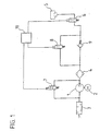
- Fig. 1 shows a level control system in a simplified representation.
- To the air supply unit include a compressor 1 that can be powered by a motor 2, as well as a silencer 3 and an air dryer 4.
- the pneumatic elements by The air supply unit to be supplied with air are air springs 5, from those in Fig. 1 for the sake of simplicity, only one is shown.
- the air springs 5 are upstream valves 6, via which the individual air springs 5 individually controlled can be.
- the valves 7, and 8 are actuated electromagnetically. You can go through an electronic control unit 10 are controlled.
- the venting or suction of air may e.g. for the level control of a vehicle with Serve air suspension.
- the compressor sucks 1 air from the environment via the silencer 3 and promotes them over the Air dryer 4 and the check valve 9 via the in-transit position Valves 6 to the air springs 5.
- the check valve 9 ensures that the air unhindered added to the system, but only controlled by the valve 8 again can be drained.
- the valves 6, 7 and 8 open. By the valve 7 is when draining in the air supply unit of the Bypassed compressor 1. The air then flows through the air dryer 4 and the Silencer 3 in the reverse direction and enters the outdoors.
- the system ensures that both the inflow of air to the system and the Discharge of air from the system is a sound attenuation.
- the air is always passed through the air dryer 4, where it is dried when flowing into the system and when flowing out of the system the retained moisture in the air dryer 4 is discharged to the outside.
- the muffler 3 will now be explained in more detail with reference to Figures 2 to 4.
- Silencer consists of individual cylindrical tube sections 11 made of rubber, z, B. made of NBR (acrylonitrile butadiene rubber) or ACM (acrylate elastomer) with a Shore hardness 75.
- the tube sections 11 are open at one end and provided at the other end with connectors 12, each to the free end towards a paragraph 13 having a reduced diameter, in the open End of the adjacent Schlauchabschittes 11 is inserted.
- the connecting pieces 12 are formed on the tube sections 11. Alternatively, they can be prepared separately and connected to the tube sections 11.
- the Connectors 12 are penetrated by holes 14, mainly in Longitudinal direction of the muffler and the diameter is significantly lower as the inner diameter of the tube sections 11, so that throttle points formed become.
- Participants give the tube sections 11 a hose that in his Inner has a plurality of chambers 15 which are arranged one behind the other and through the Throttle 14 are separated from each other.
- This hose is also at one end with a hose portion 16 is provided which has no connection piece 12, so that the Hose is open at both ends.
- the one end of the hose is with the Air supply unit connected while the other end leads into the open (Fig. 1), so that air taken in or discharged by the air supply unit passes through the hose is passed.
- the muffler of FIG. 3 is similar in its operation to that of Fig. 2. He is but not composed of individual sections, but consists of one single tube 17 made of rubber, the projections 18 at its inner diameter has, which form the throttle bodies 14 and merge integrally into the tube 17. In turn, chambers 15 are formed between the throttling points 14.
- a Silencer may e.g. by molding in a mold with a core for training the structures are made inside the tube 17.
- the chambers 15 can be about twice as long be as the throttle body 15 and the inner diameter of the tube 17 and the Hose sections 11 and 16 about twice as large as that of the throttle bodies 14th
- Typical dimensions for a model with three orifices were, for example: Total length 200 mm, length of the chambers 40 mm, diameter of the chambers 10 mm, Diameter of the throttling points 4.5 mm, wall thickness of the hose 2 mm.
- Fig. 4 In the embodiment shown in Fig. 4 are two tube sections 19 and 20 arranged parallel to each other. In their ends are connectors 21 and 22nd used. The connection of the silencer to the air supply unit as well as Exit to the outside via hose sections 23 and 24, which also on the Connecting pieces 21 and 22 are pushed. The connecting pieces 21 and 22 have channels for guiding the air, which branch at 26. The diameter of the Channels 25 is less than the inner diameter of the tube sections. The Connecting pieces 21 and 22 thus simultaneously act as throttling points.
- the Hose sections 19 and 20 thus form two chambers 27 and 28 which are parallel are arranged to each other.
- the tube sections 19, 20, 23 and 24 are made Gum, e.g. NBR or an acrylate elastomer.
- the connectors can be off Plastic, e.g. Made of polyamide.
- the air is in the muffler of the hose section 23 or 24 coming in the branches 26 in the Verbindugs Nativeen 21 and 22 in two parallel Divided flows that led in the tube sections 19 and 20 and in the second connector 22 and 21 is brought together again.
- the sound is spreading along the same paths.
- the sound is divided into two fronts that in the second connector 22 or 21 are superimposed and thereby partially cancel each other out.
Abstract
Description
Die Erfindung betrifft ein Luftversorgungsaggregat für ein Fahrzeug mit pneumatischen Einrichtungen, insb. mit Luftfedern, das einen Kompressor und einen Schalldämpfer enthält.The invention relates to an air supply unit for a vehicle with pneumatic Facilities, esp. With air springs, a compressor and a silencer contains.
Aus der DE 198 35 491 A1 ist eine pneumatische Einrichtung für ein Fahrzeug in Form einer Niveauregelanlage bekannt, die Luftfedern aufweist. Bei derartigen Niveauregelanlagen muß z.B. zur Niveauregulierung des Fahrzeuges Luft aus den Luftfedern abgelassen oder mittels des Kompressors aufgefüllt werden, wobei die Luft üblicherweise über einen Lufttrockner geführt wird. Vor allem das Ablassen der Luft ist mit lauter, unangenehmer Geräuschentwicklung verbunden. Es besteht daher das Bedürfnis, derartige Niveuaregelanlagen mit Schalldämpfern auszustatten.From DE 198 35 491 A1 is a pneumatic device for a vehicle in the form a level control system known which comprises air springs. In such Level control systems must e.g. for the level control of the vehicle air from the Air springs are drained or filled by means of the compressor, the air Usually is passed through an air dryer. Above all, the deflation of the air is associated with loud, unpleasant noise. It therefore exists Need to equip such Nueuaregelanlagen with mufflers.
Bei einem Luftversorgungsaggregat, das aus der nachveröffentlichten der DE 101 21 582 bekannt ist, weist der Schalldämpfer mehrere hintereinander angeordnete Kammern auf, die über sich diffusorartig verengende Kanäle miteinander verbunden sind. Weiterhin sind poröse Platten z.B. aus Sinterwerkstoff mit einer Vielzahl feiner Kanäle vorgesehen, durch die die Luft hindurchgeletet wird. Mit diesem Luftversorgungsaggregat konnte bereits eine deutliche Schallreduzierung erreicht werden. Der Schalldämpfer weist jedoch den Nachteil auf, dass er einen gewissen Mindestdurchmesser und eine Mindestlänge benötigt. Bei vielen modernen Fahrzeugen ist der Einbauraum so beengt, dass der Schalldämpfer aufgrund seines Volumens schwer unterzubringen ist. Zudem ist die Herstellung des Schalldämpfers aufwändig, da er in seinem Inneren eine komplizierte Struktur aufweist und aus einer Vielzahl von Einzelteilen, wie den Diffusoren, zusammengesetzt ist.In an air supply unit that from the post-published DE 101 21 582 is known, the silencer has a plurality of chambers arranged one behind the other, the diffuser-like narrowing channels are interconnected. Furthermore are porous plates e.g. made of sintered material with a variety of fine channels, through the air is passed through. With this air supply unit could already a significant sound reduction can be achieved. The muffler, however, has the disadvantage that he needs a certain minimum diameter and a minimum length. at Many modern vehicles, the installation space is so cramped that the muffler difficult to accommodate due to its volume. In addition, the production of the Muffler consuming because it has a complicated structure in its interior and composed of a plurality of individual parts, such as the diffusers.
Der Erfindung liegt daher die Aufgabe zugrunde, ein Luftversorgungsaggregat der eingangs genannten Art zur Verfügung zu stellen, das einen Schalldämpfer aufweist, der auch bei sehr beengten Verhältnissen im Fahrzeug eingebaut werden kann und auf einfache Weise herstellbar ist.The invention is therefore based on the object, an air supply unit of to provide the aforementioned type, which has a muffler, the can be installed in very tight conditions in the vehicle and on simple Way can be produced.
Diese Aufgabe wird erfindungsgemäß dadurch gelöst, dass der Schalldämpfer aus einem oder mehreren Schläuchen aus Gummi oder einem gummiähnlichen Werkstoff besteht und durch Drosselstellen in seinem Inneren in mehrere Kammern unterteilt ist.This object is achieved in that the muffler from a or more hoses made of rubber or a rubber-like material, and is divided into several chambers by throttling in its interior.
Im Gegensatz zu bisher bekannten Schalldämpfern verzichtet man bei dieser Form auf Prallplatten, Sinterscheiben, Schaumfüllungen u.ä., die dem ungehinderten Luftablaß und dem ungehinderten Luftansaugen im Wege stehen. Somit ist das Ablaßgeräusch des Luftversorgungsaggregates nicht wesentlich länger als bei einem Luftversorgungsaggregat ganz ohne Schalldämpfer. Außerdem ist der auftretende Widerstand, den der Kompressor beim Ansaugen und Ablassen überwinden muß, wesentlich geringer als bei herkömmlichen Schalldämpfern.In contrast to previously known silencers omitted in this form Impact plates, sintered disks, foam fillings, etc., which are the unimpeded air outlet and the unimpeded air intake in the way. Thus, the exhaust sound of Air supply unit not much longer than an air supply unit without silencer. In addition, the occurring resistance, the compressor must overcome when sucking and deflating, much lower than at conventional silencers.
Der Schalldämpfer ist ein Luftablaßschlauch, der kein eigenes Gehäuse notwendig macht. Das Platzproblem, das bei Dämpfungsmaßnahmen immer besteht, wird somit überwunden. Der Schlauch hat einen geringeren Durchmesser als bekannte Schalldämpfer. Aufgrund seiner Flexibilität kann er praktisch in beliebiger Weise im Fahrzeug verlegt sein. Somit kann der Schalldämpfer auch unter ungünstigen Umständen im Fahrzeug angeordnet sein. Der Schalldämpfer ist aus sehr einfachen Teilen aufgebaut. Sowohl seine Herstellung als auch seine Montage am Luftversorgungsaggregat sind in einfacher Weise möglich. Es kann auch auf standardmäßige, im Handel erhältliche Bauteile zurückgegriffen werden. The silencer is an air discharge hose that does not require a separate housing. The space problem that always exists with damping measures is thus overcome. The hose has a smaller diameter than known silencers. by virtue of Its flexibility means that it can be routed practically anywhere in the vehicle. Consequently the muffler can be arranged in the vehicle even under unfavorable circumstances. The silencer is made up of very simple parts. Both its production as Its installation on the air supply unit are possible in a simple manner. It can also be used on standard, commercially available components.
Der Schlauch kann z.B. im Spritzgießverfahren hergestellt werden, wobei durch Einlegen eines entsprechend gestalteten Kerns die Drosselstellen einstückig in den Schlauch eingeformt werden können. Diese Ausführungsform der Erfindung ist dann vorteilhaft, wenn der Schalldämpfer in großen Stückzahlen hergestellt werden soll. Der Schalldämpfer wird in einem Stück hergestellt, zusätzliche Arbeitsschritte, wie das Zusammensetzen von Einzelteilen, können entfallen. Nach einer anderen vorteilhaften Ausführungsform der Erfindung ist der Schalldämpfer aus mehreren Schlauchabschnitten zusammengesetzt, die durch Verbindungsstücke miteinander verbunden sind, wobei die Verbindungsstücke zusätzlich die Funktion von Drosselstellen übernehmen. Diese Ausführungsform der Erfindung ist dann besonders vorteilhaft, wenn der Schalldämpfer nur in geringeren Stückzahlen benötigt, da standardmäßige, nicht spezialisierte Einzelteile verwendet werden können.The hose can e.g. be produced by injection molding, wherein by inserting a correspondingly shaped core, the throttle bodies integrally into the hose can be molded. This embodiment of the invention is then advantageous if the silencer is to be produced in large numbers. The silencer is made in one piece, additional steps, such as the assembly of Individual parts, can be omitted. According to another advantageous embodiment of the Invention, the muffler is composed of several tube sections, the are interconnected by connecting pieces, wherein the connecting pieces additionally assume the function of throttle points. This embodiment of the Invention is particularly advantageous when the muffler only in minor Quantity required as standard, non-specialized items are used can.
Bei dem erfindungsgemäßen Luftversorgungsaggregat konnte durch den Schalldämpfer eine Reduzierung ders Ablaßgeräusches, aber auch des Einlaßgeräusches und von Klopfgeräuschen des Kompressors um mindestens 7 dBA erreicht werden. Die Schalldämpfung wird zum einen durch die Drosselstellen bewirkt, an denen die Schallenergie vor allem bei der kurzzeitigen, sehr intensiven Luftdurchströmung beim Luftablassen aus der Anlage verwirbelt und in Wärme umgewandelt wird. Zum anderen wirkt der weiche Werkstoff des Schlauches dämpfend. Bei dem erfindungsgemäßen Luftversorgungsaggregat konnte im Vergleich zu dem oben erwähnten bekannten Luftversorgungsaggregat, das einen aus harten Bauteilen bestehenden Schalldämpfer aufweist, nicht nur eine bessere Geräuschreduzierung erreicht werden, sondern das verbleibende Geräusch ist auch angenehmer und weniger hart. Eine hohe Qualität der Geräuschdämpfung kann durch geeignete Eigenschaften des Schlauchwerkstoffes erzielt werden. Es hat sich gezeigt, dass eine besonders gute Dämfung erreicht werden konnte, wenn der Schlauch eine Shore-Härte zwischen 70 und 80, vorzugsweise von etwa 75 (angegeben in Shore A) aufwies.In the air supply unit according to the invention could by the muffler a reduction of the exhaust noise, but also the intake noise and knocking noises of the compressor can be achieved by at least 7 dBA. The soundproofing is caused on the one hand by the throttle points, where the sound energy especially at the short-term, very intense air flow when deflating the system is swirled and converted into heat. On the other hand, the soft material of the Steaming hose. In the air supply unit according to the invention could in Compared to the above-mentioned known air supply unit, the one from hard components existing silencer, not only a better noise reduction be achieved, but the remaining noise is also more pleasant and less hard. A high quality of noise reduction can be achieved by suitable Properties of the hose material can be achieved. It has been shown that one Particularly good damping could be achieved if the hose has a Shore hardness between 70 and 80, preferably about 75 (indicated in Shore A).
Als dritter wesentlicher Effekt zur Schallreduzierung wirken bei der Erfindung Reflexionen in den Kammern, die zu einer Auslöschung des Schalls durch phasenverschobene, reflektierte Schallwellen gleicher Frequenz führen. Um diesen Effekt optimal zu nutzen, sind bei einer vorteilhaften Ausführungsform der Erfindung die Kammern so ausgebildet, dass ihre Längen in einem ganzzahligen Verhältnis zu der Wellenlänge derjenigen Anteile des Schalls stehen, die vorrangig gedämpft werden sollen. Der Schalldämpfer kann somit durch die Wahl geeigneter Abmessungen optimiert werden, wobei diese Abmessungen jedoch abhängig von den zu dämpfenden Geräuschen und damit von den weiteren Komponenten des Luftversorgungsaggregates, insb. des Kompressors, sind. Weiterhin wird eine starke Reduzierung tiefer Frequenzen (bis ca. 1000 Hz) bewirkt, da sich diese Schallwellen nicht ausbreiten können, weil ihre Wellenlänge größer ist als die Abstände zwischen den Drosselstellen.The third significant effect for reducing the sound effect in the invention Reflections in the chambers, which leads to an extinguishing of the sound phase-shifted, reflected sound waves of the same frequency lead. To this effect to use optimally, are in an advantageous embodiment of the invention, the Chambers designed so that their lengths in an integer ratio to the Wavelength of those portions of the sound are to be attenuated priority. The muffler can thus be optimized by choosing suitable dimensions, however, these dimensions depend on the noise to be damped and thus from the other components of the air supply unit, in particular the compressor, are. Furthermore, a strong reduction of low frequencies (up to about 1000 Hz) is effected because these sound waves can not propagate because their wavelength is greater than that Distances between the throttle points.
Nach einer vorteilhaften Ausführungsform der Erfindung besteht der Schalldämpfer aus einem Schlauch, in dem die Kammern hintereinander angeordnet sind, so dass sie von der Luft der Reihe nach durchströmt werden können. Eine derartige Ausführungsform der Erfindung hat den Vorteil, besonders einfach zu sein und einen besonders schlanken Schalldämpfer aufzuweisen.According to an advantageous embodiment of the invention, the muffler is made a hose in which the chambers are arranged one behind the other, so that they are separated from the Air can be flowed through in order. Such an embodiment of Invention has the advantage of being particularly simple and a particularly slim Have silencers.
Bei einer anderen vorteilhaften Ausführungsform der Erfindung weist der Schalldämpfer auf seinem mittleren Abschnitt zwei oder mehrere einander parallele Schläuche auf. Diese Ausführungsform hat den Vorteil einer besonders kurzen, kompakten Bauweise. Bei einem Schalldämpfer dieser Bauweise wird der Luftstrom in parallele Ströme aufgeteilt und nach einer gewissen Strecke wieder zusammengeführt. Die Schallwellen breiten sich in den parallelen Schläuchen aus und überlagern einander an den Stellen, wo sie wieder zusammengeführt werden, wobei es zur Auslöschung von phasenverschobenen Schallwellen gleicher Frequenz kommt. Bei diesem Schalldämpfer sind zwei oder mehr Kammern parallel zueinander angeordnet, wobei die Verzweigungsstellen auch gleichzeitig als Drosselstellen ausgebildet sein können. Dieser Schalldämpfer ist besonders gut in der oben beschriebenen Weise aus mehreren Schlauchabschnitten und Verbindungsstücken herzustellen, wobei die Verbindungsstücke Verzweigungen aufweisen. In another advantageous embodiment of the invention, the silencer on its middle section two or more parallel hoses. These Embodiment has the advantage of a particularly short, compact design. At a Silencer of this design, the air flow is divided into parallel streams and after merged again for a certain distance. The sound waves spread in the parallel hoses and overlap each other in the places where they again be merged, whereby it is for the cancellation of phase-shifted Sound waves of the same frequency comes. In this muffler are two or more Chambers arranged parallel to each other, wherein the branching points also can be formed simultaneously as throttle points. This silencer is special good in the manner described above from several tube sections and Connectors produce, with the connectors branches exhibit.
Es liegt weiterhin im Rahmen der Erfindung, Schalldämpfer mit in Reihe liegenden und mit parallel geschalteten Kammern miteinander zu kombinieren.It is also within the scope of the invention, silencer with in-line and to combine with parallel chambers.
Weitere Einzelheiten der Erfindung werden anhand der Zeichnung erläutert, in der Ausführungsbeispiele der Erfindung dargestellt sind. Es zeigen:
- Fig. 1
- eine Niveauregelanlage für ein Fahrzeug mit einem erfindungsgemäß Luftversorgungsaggregat in schematischer Darstellung,
- Fig. 2
- einen Schalldämpfer für das Luftversorgungsaggregat nach Fig. 1 im Längsschnitt,
- Fig. 3
- eine gegenüber Fig. 2 abgewandelte Ausführungsform des Schalldämpfers im Längsschnitt und
- Fig. 4
- eine weitere gegenüber Fig. 2 abgewandelte Ausführungsform des Schalldämpfers im Längsschnitt.
- Fig. 1
- a level control system for a vehicle with an air supply unit according to the invention in a schematic representation,
- Fig. 2
- a silencer for the air supply unit according to Fig. 1 in longitudinal section,
- Fig. 3
- a comparison with Fig. 2 modified embodiment of the muffler in longitudinal section and
- Fig. 4
- a further compared to Fig. 2 modified embodiment of the muffler in longitudinal section.
Fig. 1 zeigt eine Niveauregelanlage in vereinfachter Darstellung. Zu dem Luftversorgungsaggregat
gehören ein Kompressor 1, der durch einen Motor 2 angetrieben werden kann,
sowie ein Schalldämpfer 3 und ein Lufttrockner 4. Die pneumatischen Elemente, die durch
das Luftversorgungsaggregat mit Luft versorgt werden sollen, sind Luftfedern 5, von
denen in Fig. 1 der Einfachheit halber nur eine dargestellt ist. Den Luftfedern 5 sind
jeweils Ventile 6 vorgeschaltet, über die die einzelnen Luftfedern 5 individuell angesteuert
werden können. In der Anlage sind weitere Ventile 7 und 8 sowie ein Rückschlagventil 9
vorgesehen. Die Ventile 6, 7 und 8 werden elektromagnetisch betätigt. Sie können durch
eine elektronische Steuereinheit 10 gesteuert werden.Fig. 1 shows a level control system in a simplified representation. To the air supply unit
include a compressor 1 that can be powered by a
Das Ablassen oder Ansaugen von Luft kann z.B. zur Niveauregelung eines Fahrzeuges mit
Luftfederung dienen. Um die Druckluftanlage mit Luft aufzufüllen, saugt der Kompressor
1 Luft aus der Umgebung über den Schalldämpfer 3 an und fördert sie über den
Lufttrockner 4 und das Rückschlagventil 9 über die in Durchgangsstellung befindlichen
Ventile 6 zu den Luftfedern 5. Das Rückschlagventil 9 sorgt dafür, dass die Luft
ungehindert in die Anlage aufgenommen, jedoch nur gesteuert über das Ventil 8 wieder
abgelassen werden kann. Zum Ablassen von Luft aus der Anlage werden die Ventile 6, 7
und 8 geöffnet. Durch das Ventil 7 wird beim Ablassen im Luftversorgungsaggregat der
Verdichter 1 umgangen. Die Luft durchströmt dann den Lufttrockner 4 und den
Schalldämpfer 3 in umgekehrter Richtung und gelangt ins Freie. Durch diesen Aufbau der
Anlage ist sichergestellt, dass sowohl beim Zuströmen von Luft zur Anlage als auch beim
Ablassen von Luft aus der Anlage eine Schalldämpfung erfolgt. Zudem wird die Luft stets
über den Lufttrockner 4 geführt, wobei sie beim Zuströmen in die Anlage getrocknet wird
und beim Abströmen aus der Anlage die im Lufttrockner 4 zurückgehaltene Feuchtigkeit
nach außen abgeführt wird.The venting or suction of air may e.g. for the level control of a vehicle with
Serve air suspension. To top up the compressed air system with air, the compressor sucks
1 air from the environment via the
Der Schalldämpfer 3 wird nun anhand der Figuren 2 bis 4 näher erläutert werden. Der
Schalldämpfer gemäß Fig. 2 besteht aus einzelnen zylindrischen Schlauchabschnitten 11
aus Gummi, z,B. aus NBR (Acrylnitril-Butadienn-Kautschuk) oder ACM (Acrylat-Elastomer)
mit einer Shore-Härte 75. Die Schlauchabschnitte 11 sind an einem Ende offen
und am anderen Ende mit Verbindungsstücken 12 versehen, die jeweils zum freien Ende
hin einen Absatz 13 mit einem verringerten Durchmesser aufweisen, der in das offene
Ende des benachbarten Schlauchabschittes 11 eingesetzt ist. Die Verbindungsstücke 12
sind an die Schlauchabschnitte 11 angeformt. Alternativ dazu können sie jedoch auch
gesondert hergestellt und mit den Schlauchabschnitten 11 verbunden werden. Die
Verbindungsstücke 12 werden von Bohrungen 14 durchsetzt, die hauptsächlich in
Längsrichtung des Schalldämpfers verlaufen und deren Durchmesser deutlich geringer ist
als der Innendurchmesser der Schlauchabschnitte 11, so dass Drosselstellen gebildet
werden. Zusammengestzt ergeben die Schlauchabschnitte 11 einen Schlauch, der in seinem
Inneren mehrere Kammern 15 aufweist, die hintereinander angeordnet und durch die
Drosselstellen 14 voneinander getrennt sind. Dieser Schlauch ist ferner an einem Ende mit
einem Schlauchabschnitt 16 versehen, der kein Verbindungsstück 12 aufweist, so dass der
Schlauch an beiden Enden offen ist. Das eine Ende des Schlauches ist mit dem
Luftversorgungsaggregat verbunden, während das andere Ende ins Freie führt (Fig. 1), so
dass Luft, die vom Luftversorgungsaggregat aufgenommen oder abgegeben wird, durch
den Schlauch hindurchgeführt wird.The
Der Schalldämpfer gemäß Fig. 3 gleicht in seiner Wirkungsweise dem aus Fig. 2. Er ist
jedoch nicht aus einzelnen Abschnitten zusammengesetzt, sondern besteht aus einem
einzigen Schlauch 17 aus Gummi, der an seinem Innendurchmesser Vorsprünge 18
aufweist, die die Drosselstellen 14 bilden und einstückig in den Schlauch 17 übergehen.
Zwischen den Drosselstellen 14 sind wiederum Kammern 15 ausgebildet. Ein derartiger
Schalldämpfer kann z.B. durch Abformen in einr Form mit einem Kern für die Ausbildung
der Strukturen im Inneren des Schlauches 17 hergestellt werden.The muffler of FIG. 3 is similar in its operation to that of Fig. 2. He is
but not composed of individual sections, but consists of one
Bei Schalldämpfern gemäß den Fig 2 und 3 können die Kammern 15 etwa doppelt so lang
sein wie die Drosselstellen 15 und der Innendurchmesser des Schlauches 17 bzw. der
Schlauchabschnitte 11 und 16 etwa doppelt so groß wie der der Drosselstellen 14.
Typische Abmessungen für ein Modell mit drei Drosselstellen aufwies sind z.B.:
Gesamtlänge 200 mm, Länge der Kammern 40 mm, Durchmesser der Kammern 10 mm,
Durchmesser der Drosselstellen 4,5 mm, Wandstärke des Schlauches 2 mm.In mufflers according to Figures 2 and 3, the
Bei dem in Fig. 4 dargestellten Ausführugsbeispiel sind zwei Schlauchabschnitte 19 und
20 parallel zueinander angeordnet. In ihre Enden sind Verbindungsstücke 21 und 22
eingesetzt. Die Anbindung des Schalldämpfer an das Luftversorgungsaggregat sowie sein
Ausgang ins Freie erfolgt über Schlauchabschnitte 23 und 24, die ebenfalls auf die
Verbindungsstücke 21 bzw. 22 aufgeschoben sind. Die Verbindungsstücke 21 und 22
weisen Kanäle zur Führung der Luft auf, die sich bei 26 verzweigen. Der Durchmesser der
Kanäle 25 ist geringer als der Innendurchmesser der Schlauchabschnitte. Die
Verbindungsstücke 21 und 22 wirken somit gleichzeitig als Drosselstellen. Die
Schlauchabschnitte 19 und 20 bilden somit zwei Kammern 27 und 28, die parallel
zueinander angeordnet sind. Die Schlauchabschnitte 19, 20, 23 und 24 bestehen aus
Gummi, z.B. NBR oder einem Acrylat-Elastomer. Die Verbindungsstücke können aus
Kunststoff, z.B. aus Polyamid bestehen. In the embodiment shown in Fig. 4 are two
Die Luft wird in dem Schalldämpfer von dem Schlauchabschnitt 23 oder 24 kommend in
den Verzweigungen 26 in den Verbindugsstücken 21 bzw. 22 in zwei parallele
Strömungen aufgeteilt, die in den Schlauchabschnitten 19 und 20 geführt und in dem
zweiten Verbindungsstück 22 bzw. 21 wieder zusammengeführt wird. Der Schall breitet
sich entlang der selben Wege aus. Bei der Verzweigung 26 im ersten Verbindungsstück 21
oder 22 wird der Schall in zwei Fronten aufgeteilt, die im zweiten Verbindungsstück 22
bzw. 21 überlagert werden und sich dabei teilweise gegenseitig auslöschen. The air is in the muffler of the
- 11
- Kompressorcompressor
- 22
- Motorengine
- 33
- Schalldämpfersilencer
- 44
- Lufttrocknerair dryer
- 55
- Luftfederair spring
- 6, 7, 86, 7, 8
- Elektromagnet-VentileSolenoid valves
- 99
- Rückschlagventilcheck valve
- 1010
- Elekronische SteuerungElectronic control
- 1111
- Schlauchabschnitthose section
- 1212
- Verbindungsstückjoint
- 1313
- Absatzparagraph
- 1414
- Drosselstellerestriction
- 1515
- Kammerchamber
- 1616
- Schlauchabschnitthose section
- 1717
- Schlauchtube
- 1818
- Vorsprunghead Start
- 19, 2019, 20
- Schlauchabschnittetube sections
- 21, 2221, 22
- VerbindusgsstückeVerbindusgsstücke
- 23, 2323, 23
- Schlauchabschnittetube sections
- 2525
- Kanalchannel
- 2626
- Verzweigungbranch
- 27, 2827, 28
- Kammernchambers
Claims (8)
Applications Claiming Priority (2)
| Application Number | Priority Date | Filing Date | Title |
|---|---|---|---|
| DE10152153 | 2001-10-25 | ||
| DE10152153A DE10152153C2 (en) | 2001-10-25 | 2001-10-25 | Silencer of an air supply unit for a vehicle |
Publications (3)
| Publication Number | Publication Date |
|---|---|
| EP1306239A2 true EP1306239A2 (en) | 2003-05-02 |
| EP1306239A3 EP1306239A3 (en) | 2004-11-17 |
| EP1306239B1 EP1306239B1 (en) | 2008-08-06 |
Family
ID=7703349
Family Applications (1)
| Application Number | Title | Priority Date | Filing Date |
|---|---|---|---|
| EP02018423A Expired - Lifetime EP1306239B1 (en) | 2001-10-25 | 2002-08-16 | Air supply unit for a vehicle |
Country Status (4)
| Country | Link |
|---|---|
| US (1) | US20030080481A1 (en) |
| EP (1) | EP1306239B1 (en) |
| JP (1) | JP2003148123A (en) |
| DE (2) | DE10152153C2 (en) |
Cited By (3)
| Publication number | Priority date | Publication date | Assignee | Title |
|---|---|---|---|---|
| WO2011160735A1 (en) * | 2010-06-24 | 2011-12-29 | Wabco Gmbh | Air supply device for a vehicle having pneumatic devices |
| EP1411244B1 (en) | 2002-10-16 | 2015-09-09 | WABCO GmbH | Noise damping device for an air compressor unit |
| TWI727808B (en) * | 2020-05-22 | 2021-05-11 | 林鈺文 | Noise reduction device of air compressor |
Families Citing this family (4)
| Publication number | Priority date | Publication date | Assignee | Title |
|---|---|---|---|---|
| DE102010047402A1 (en) | 2010-10-02 | 2012-04-05 | Wabco Gmbh | Compressor i.e. reciprocating compressor, for pneumatic spring system of vehicle i.e. motor car, has electrically or pneumatically switchable valve connected with return line that is opened and closed in respective positions of valve |
| US20150275882A1 (en) * | 2012-09-25 | 2015-10-01 | Jaguar Land Rover Limited | Noise suppressor for vehicle suspension system |
| US20200362845A1 (en) * | 2019-05-14 | 2020-11-19 | Cummins Inc. | Resonance free compressor inlet acoustic suppressor |
| EP4100661A4 (en) * | 2020-02-06 | 2024-03-27 | Bruce V Weeks | Impact absorption elements, systems, and methods of use |
Citations (2)
| Publication number | Priority date | Publication date | Assignee | Title |
|---|---|---|---|---|
| DE19835491A1 (en) | 1998-08-06 | 2000-02-17 | Continental Ag | Level control device for vehicles with air springs |
| DE10121582A1 (en) | 2001-05-03 | 2002-11-14 | Continental Ag | Air supply unit for vehicle with pneumatic equipment has silencer with several chambers arranged in series with each connected to adjoining chamber through channels whose cross section widens out from first connection to second connection |
Family Cites Families (17)
| Publication number | Priority date | Publication date | Assignee | Title |
|---|---|---|---|---|
| GB471431A (en) * | 1936-03-03 | 1937-09-03 | Frederick Heather | Improvements in and relating to silencers for gaseous currents |
| US2903085A (en) * | 1954-07-06 | 1959-09-08 | James L Matheny | Engine exhaust muffler |
| FR1272608A (en) * | 1960-08-19 | 1961-09-29 | Polycarbure | Silencer for pulsating gas flow |
| US3187837A (en) * | 1963-08-28 | 1965-06-08 | Charles G Beeching | Free flow acoustic silencer constructed of resilient material |
| DE2134178A1 (en) * | 1971-03-03 | 1972-09-21 | VEB Monsator Haushaltgroßgeratekom binat Schwarzenberg, χ 9430 Schwarzen berg | Steamers for compressors, especially for hermetic refrigerant compressors |
| JPS528506A (en) * | 1975-07-09 | 1977-01-22 | Hitachi Ltd | All closed motor driven compressor |
| US4234054A (en) * | 1978-04-18 | 1980-11-18 | Chapin John S | Multi-duct muffler |
| US4239461A (en) * | 1978-11-06 | 1980-12-16 | Copeland Corporation | Compressor induction system |
| US4285534A (en) * | 1979-12-28 | 1981-08-25 | Nichirin Rubber Industrial Co., Ltd. | Pulsation-absorbing flexible pipe for pressure fluid device |
| US4448538A (en) * | 1982-04-06 | 1984-05-15 | Juval Mantel | Device for reducing static and dynamic pressures in pipelines, particularly of solid-borne sound in tubular conduits |
| DE3311682A1 (en) * | 1983-03-30 | 1984-10-04 | Knorr-Bremse GmbH, 8000 München | AIR DRYER |
| US4915594A (en) * | 1986-04-25 | 1990-04-10 | Campbell Hausfeld/Scott Fetzer Company | Improved compressor crankshaft |
| GB9119534D0 (en) * | 1991-09-13 | 1991-10-23 | Dunlop Ltd | Vehicle suspension system |
| US5183974A (en) * | 1992-04-03 | 1993-02-02 | General Motors Corporation | Gas pulsation attenuator for automotive air conditioning compressor |
| FI94903C (en) * | 1994-03-09 | 1995-11-10 | Neles Jamesbury Oy | Method of attenuating noise caused by throttling of gas flow and provided with a gas flow duct |
| US5435699A (en) * | 1994-04-05 | 1995-07-25 | Ford Motor Company | Accumulator for air conditioning system |
| WO1999051909A1 (en) * | 1998-04-01 | 1999-10-14 | Aeroquip-Vickers International Gmbh | Device for reducing pulsations and/or vibrations in hydraulic hose line systems |
-
2001
- 2001-10-25 DE DE10152153A patent/DE10152153C2/en not_active Expired - Fee Related
-
2002
- 2002-08-16 DE DE50212593T patent/DE50212593D1/en not_active Expired - Lifetime
- 2002-08-16 EP EP02018423A patent/EP1306239B1/en not_active Expired - Lifetime
- 2002-09-26 JP JP2002280743A patent/JP2003148123A/en not_active Withdrawn
- 2002-10-25 US US10/279,976 patent/US20030080481A1/en not_active Abandoned
Patent Citations (2)
| Publication number | Priority date | Publication date | Assignee | Title |
|---|---|---|---|---|
| DE19835491A1 (en) | 1998-08-06 | 2000-02-17 | Continental Ag | Level control device for vehicles with air springs |
| DE10121582A1 (en) | 2001-05-03 | 2002-11-14 | Continental Ag | Air supply unit for vehicle with pneumatic equipment has silencer with several chambers arranged in series with each connected to adjoining chamber through channels whose cross section widens out from first connection to second connection |
Cited By (6)
| Publication number | Priority date | Publication date | Assignee | Title |
|---|---|---|---|---|
| EP1411244B1 (en) | 2002-10-16 | 2015-09-09 | WABCO GmbH | Noise damping device for an air compressor unit |
| WO2011160735A1 (en) * | 2010-06-24 | 2011-12-29 | Wabco Gmbh | Air supply device for a vehicle having pneumatic devices |
| CN102958715A (en) * | 2010-06-24 | 2013-03-06 | 威伯科有限公司 | Air supply device for a vehicle having pneumatic devices |
| KR101384870B1 (en) * | 2010-06-24 | 2014-04-15 | 바브코 게엠베하 | Air supply device for a vehicle having pneumatic devices |
| CN102958715B (en) * | 2010-06-24 | 2016-01-13 | 威伯科有限公司 | For the air supply device of the vehicle with pneumatics |
| TWI727808B (en) * | 2020-05-22 | 2021-05-11 | 林鈺文 | Noise reduction device of air compressor |
Also Published As
| Publication number | Publication date |
|---|---|
| US20030080481A1 (en) | 2003-05-01 |
| DE10152153A1 (en) | 2003-05-15 |
| JP2003148123A (en) | 2003-05-21 |
| DE10152153C2 (en) | 2003-11-20 |
| EP1306239A3 (en) | 2004-11-17 |
| EP1306239B1 (en) | 2008-08-06 |
| DE50212593D1 (en) | 2008-09-18 |
Similar Documents
| Publication | Publication Date | Title |
|---|---|---|
| DE3429633C2 (en) | ||
| DE19720410A1 (en) | Vehicle exhaust silencer | |
| DE102005041692A1 (en) | Silencer for an exhaust system | |
| DE19956172C5 (en) | Double chamber damper | |
| WO2000045044A1 (en) | Intake device having a conducting section which comprises orifices | |
| DE10121582C2 (en) | Air supply unit for vehicles with a compressor and a silencer | |
| DE202006003989U1 (en) | Compressed air sound absorber for pneumatic applications comprises a sound absorbing unit having several absorption zones with different frequency-dependent sound damping properties | |
| EP1306239B1 (en) | Air supply unit for a vehicle | |
| DE102007000793A1 (en) | Air vacuum fixture for internal combustion (IC) engine, has sound transfer sections around inner tubing, and space defined inner and outer tubings and having one end opened on air inlet port side of inner tubing and another end closed | |
| DE102007025572A1 (en) | fluid channel | |
| EP1549535B1 (en) | Washing device for a glass pane in a motor vehicle | |
| DE60008774T2 (en) | WEDGE-SECTION MULTIBAY resonator | |
| EP1321639B2 (en) | Silencer arrangement | |
| EP1484237A2 (en) | Spoiler for a vehicle | |
| DE3807948A1 (en) | Silencer for vehicle engines | |
| DE102004029221A1 (en) | Acoustic damping device and device for conducting a fluid | |
| DE4419219A1 (en) | Sound damping assembly for suction manifold air ducts of vehicle IC engine | |
| EP1524004B1 (en) | Noise damping assembly for an inhalation device | |
| DE2738601C2 (en) | silencer | |
| EP1400662A1 (en) | Silencer with resonator | |
| DE202004005746U1 (en) | Compressed air sound damping system for a pneumatic component has a through-channel with a constant flow cross-section over its whole length | |
| DE3836589C2 (en) | Compact silencer for commercial vehicles | |
| EP1049866B1 (en) | Air filter fitted with a silencer for internal combustion engines | |
| DE3931228A1 (en) | Gas conduit silencer system - has absorbent slides widening and tapering alternately from inlet with passages in between | |
| DE8006103U1 (en) | ABSORPTION SILENCER |
Legal Events
| Date | Code | Title | Description |
|---|---|---|---|
| PUAI | Public reference made under article 153(3) epc to a published international application that has entered the european phase |
Free format text: ORIGINAL CODE: 0009012 |
|
| AK | Designated contracting states |
Designated state(s): AT BE BG CH CY CZ DE DK EE ES FI FR GB GR IE IT LI LU MC NL PT SE SK TR |
|
| AX | Request for extension of the european patent |
Extension state: AL LT LV MK RO SI |
|
| PUAL | Search report despatched |
Free format text: ORIGINAL CODE: 0009013 |
|
| AK | Designated contracting states |
Kind code of ref document: A3 Designated state(s): AT BE BG CH CY CZ DE DK EE ES FI FR GB GR IE IT LI LU MC NL PT SE SK TR |
|
| AX | Request for extension of the european patent |
Extension state: AL LT LV MK RO SI |
|
| RIC1 | Information provided on ipc code assigned before grant |
Ipc: 7F 01N 7/16 B Ipc: 7B 60G 17/052 A Ipc: 7F 04B 39/00 B |
|
| 17P | Request for examination filed |
Effective date: 20050517 |
|
| AKX | Designation fees paid |
Designated state(s): DE FR GB IT |
|
| 17Q | First examination report despatched |
Effective date: 20071105 |
|
| GRAP | Despatch of communication of intention to grant a patent |
Free format text: ORIGINAL CODE: EPIDOSNIGR1 |
|
| GRAS | Grant fee paid |
Free format text: ORIGINAL CODE: EPIDOSNIGR3 |
|
| GRAA | (expected) grant |
Free format text: ORIGINAL CODE: 0009210 |
|
| AK | Designated contracting states |
Kind code of ref document: B1 Designated state(s): DE FR GB IT |
|
| REG | Reference to a national code |
Ref country code: GB Ref legal event code: FG4D Free format text: NOT ENGLISH |
|
| REF | Corresponds to: |
Ref document number: 50212593 Country of ref document: DE Date of ref document: 20080918 Kind code of ref document: P |
|
| PLBE | No opposition filed within time limit |
Free format text: ORIGINAL CODE: 0009261 |
|
| STAA | Information on the status of an ep patent application or granted ep patent |
Free format text: STATUS: NO OPPOSITION FILED WITHIN TIME LIMIT |
|
| 26N | No opposition filed |
Effective date: 20090507 |
|
| GBPC | Gb: european patent ceased through non-payment of renewal fee |
Effective date: 20081106 |
|
| PG25 | Lapsed in a contracting state [announced via postgrant information from national office to epo] |
Ref country code: IT Free format text: LAPSE BECAUSE OF FAILURE TO SUBMIT A TRANSLATION OF THE DESCRIPTION OR TO PAY THE FEE WITHIN THE PRESCRIBED TIME-LIMIT Effective date: 20080806 |
|
| PG25 | Lapsed in a contracting state [announced via postgrant information from national office to epo] |
Ref country code: GB Free format text: LAPSE BECAUSE OF NON-PAYMENT OF DUE FEES Effective date: 20081106 |
|
| REG | Reference to a national code |
Ref country code: DE Ref legal event code: R081 Ref document number: 50212593 Country of ref document: DE Owner name: CONTINENTAL TEVES AG CO. OHG, DE Free format text: FORMER OWNER: CONTINENTAL AKTIENGESELLSCHAFT, 30165 HANNOVER, DE Effective date: 20110414 Ref country code: DE Ref legal event code: R081 Ref document number: 50212593 Country of ref document: DE Owner name: CONTINENTAL TEVES AG & CO. OHG, DE Free format text: FORMER OWNER: CONTINENTAL AKTIENGESELLSCHAFT, 30165 HANNOVER, DE Effective date: 20110414 |
|
| REG | Reference to a national code |
Ref country code: FR Ref legal event code: PLFP Year of fee payment: 15 |
|
| REG | Reference to a national code |
Ref country code: FR Ref legal event code: PLFP Year of fee payment: 16 |
|
| REG | Reference to a national code |
Ref country code: FR Ref legal event code: PLFP Year of fee payment: 17 |
|
| PGFP | Annual fee paid to national office [announced via postgrant information from national office to epo] |
Ref country code: FR Payment date: 20190822 Year of fee payment: 18 Ref country code: DE Payment date: 20190831 Year of fee payment: 18 |
|
| REG | Reference to a national code |
Ref country code: DE Ref legal event code: R119 Ref document number: 50212593 Country of ref document: DE |
|
| PG25 | Lapsed in a contracting state [announced via postgrant information from national office to epo] |
Ref country code: DE Free format text: LAPSE BECAUSE OF NON-PAYMENT OF DUE FEES Effective date: 20210302 Ref country code: FR Free format text: LAPSE BECAUSE OF NON-PAYMENT OF DUE FEES Effective date: 20200831 |