EP1306286A1 - Shock-absorbing tilt type steering column - Google Patents
Shock-absorbing tilt type steering column Download PDFInfo
- Publication number
- EP1306286A1 EP1306286A1 EP02023691A EP02023691A EP1306286A1 EP 1306286 A1 EP1306286 A1 EP 1306286A1 EP 02023691 A EP02023691 A EP 02023691A EP 02023691 A EP02023691 A EP 02023691A EP 1306286 A1 EP1306286 A1 EP 1306286A1
- Authority
- EP
- European Patent Office
- Prior art keywords
- section
- distance bracket
- side wall
- shock
- coupler
- Prior art date
- Legal status (The legal status is an assumption and is not a legal conclusion. Google has not performed a legal analysis and makes no representation as to the accuracy of the status listed.)
- Withdrawn
Links
Images


Classifications
-
- B—PERFORMING OPERATIONS; TRANSPORTING
- B62—LAND VEHICLES FOR TRAVELLING OTHERWISE THAN ON RAILS
- B62D—MOTOR VEHICLES; TRAILERS
- B62D1/00—Steering controls, i.e. means for initiating a change of direction of the vehicle
- B62D1/02—Steering controls, i.e. means for initiating a change of direction of the vehicle vehicle-mounted
- B62D1/16—Steering columns
- B62D1/18—Steering columns yieldable or adjustable, e.g. tiltable
- B62D1/19—Steering columns yieldable or adjustable, e.g. tiltable incorporating energy-absorbing arrangements, e.g. by being yieldable or collapsible
- B62D1/195—Yieldable supports for the steering column
Definitions
- the present invention relates to a tilt type steering column for a motor vehicle. Especially, the present invention relates to a shock-absorbing mechanism of the tilt type steering column.
- a tilt type steering column allows a steering wheel to move upward and downward so as to secure a proper driving position (attitude) of a seat occupant.
- the tilt type steering column can have the following construction:
- the shock-absorbing mechanism of the tilt type steering column can have the following functions:
- a steering shaft 19 is rotatably supported by a bearing 20 of a column jacket 21.
- a support bracket 22 is formed with a vehicular body mounting section 23.
- the column jacket 21 has a rear end side which is secured to the vehicular body by way of the vehicular body mounting section 23.
- a distance bracket 24 coupling with the column jacket 21 is formed with an engagement groove 25 opening rearward.
- the tilt bolt 26 engages with the engagement groove 25 in such a manner that the tilt bolt 26 can disengage from the engagement groove 25 when an excessive load ⁇ greater than an allowable load (upper limit) ⁇ is applied to the distance bracket 24.
- the support bracket 22 has a side wall 27 which is formed with an elongate hole 28. The tilt bolt 26 engages with the elongate hole 28, thus allowing the distance bracket 24 to slide upward and downward. Moreover, operating a tilt lever 29 allows the support bracket 22 to tighten and/or relax the distance bracket 24.
- the shock-absorbing mechanism has the following construction:
- the above shock-absorbing mechanism can bring about the following effects:
- the side wall 27 of the support bracket 22 is in need of a certain dimension for allowing the elongate hole 28 (opening in the side wall 27) to secure a predetermined space for tilting the steering column.
- the side wall 27 dangling downward from the vehicular body mounting section 23 of the support bracket 22 becomes greater than the elongate hole 28 in overall dimension.
- a lower section of the support bracket 22 may touch the seat occupant's knee or thigh, thus discomforting the seat occupant.
- the energy absorber 30 is partly exposed below the support bracket 22.
- the energy absorber 30 plastically deformed in the secondary collision may also touch the seat occupant's knee or thigh.
- a cover and the like is supposed to add to the lowermost position of the support bracket 22, resulting in further diminished space above the seat occupant's knee or thigh.
- a shock-absorbing tilt type steering column comprising:
- a shock-absorbing steering system comprising:
- a column jacket 1 which is formed through a drawing into a stepped cylinder.
- the column jacket 1 defines a rear end side (right in Fig. 1) to which a unit mounting bracket 2 is fixed.
- An upper clamp 3 which acts as a support bracket supports substantially a center section of the column jacket 1 to a vehicular body.
- the column jacket 1 defines a front end side (left in Fig. 1) which is supported to the vehicular body by means of a lower clamp 4.
- a steering shaft 5 is inserted into the column jacket 1 concentrically with the column jacket 1.
- the steering shaft 5 is formed through the drawing into a stepped cylinder.
- the steering shaft 5 defines a rear end side (right in Fig. 1) which is formed with an engagement section 6 for mounting a steering wheel.
- a bearing 7 which is disposed at the rear end of the column jacket 1 in such a manner as to be interposed between the column jacket 1 and the steering shaft 5.
- a rubber bush 8 is interposed between a front end side of the steering shaft 5 and the front end side of the column jacket 1, in such a manner that the steering shaft 5 is rotatable about an axis of the column jacket 1.
- a stopper 9 (nut) abutting on the bearing 7 is fitted to the rear end side of the steering shaft 5.
- the front end side of the steering shaft 5 can connect to an intermediary shaft (not shown) by way of a universal joint 10.
- a shock-absorbing mechanism is adopted into the upper clamp 3 and the lower clamp 4.
- the upper clamp 3 includes a pair of a first side wall 3aF and a second side wall 3aS, a pair of a first front wall 3bF and a second front wall 3bS, and a pair of a first vehicular body fixture 3cF and a second vehicular body fixture 3cS.
- the upper clamp 3 can be formed in the following manner:
- the upper clamp 3 is formed with a pair of a first reinforcement 3eF and a second reinforcement 3eS.
- the first reinforcement 3eF is so machined as to reinforce a first fold section defined between the first front wall 3bF and the first vehicular body fixture 3cF
- the second reinforcement 3eS is so machined as to reinforce a second fold section defined between the second front wall 3bS and the second vehicular body fixture 3cS.
- the allowable load is defined as an upper limit. Therefore, an excessive load ⁇ greater than the allowable load (upper limit) ⁇ caused in a vehicular collision and the like may deform the first front wall 3bF and the second front wall 3bS forward, respectively, relative to the first vehicular body fixture 3cF and the second vehicular body fixture 3cS.
- the upper clamp 3 is formed with a first wavy section 3dF and a second wavy section 3dS which are disposed between the first vehicular body fixture 3cF and the second vehicular body fixture 3cS.
- the first wavy section 3dF and the second wavy section 3dS are formed for the following cause:
- first through hole 3gF and a second through hole 3gS for inserting bolts which are used for fixing the upper clamp 3 to the vehicular body.
- the side wall 3a is formed with an elongate hole 3f for a tilt bolt 13.
- the side wall 3a is determined in height for the following construction:
- the distance bracket 11 has a first lower end 11cF and a second lower end 11cS which couple with the upper outer periphery of the column jacket 1 through a welding and the like.
- the distance bracket 11 has a cross section which is a groove wall shaped substantially into an English alphabet "C” turned clockwise by 90° (similar to a Japanese katakana character " " turned counterclockwise by 90°).
- Fig. 1 the distance bracket 11 has a cross section which is a groove wall shaped substantially into an English alphabet "C” turned clockwise by 90° (similar to a Japanese katakana character " " turned counterclockwise by 90°).
- an upper side wall of the distance bracket 11 has a front end ⁇ left end in Fig. 5A ⁇ formed with an engagement port 11b which is a cutout shaped substantially into an English alphabet "T” turned clockwise by 90°.
- the engagement port 11b is defined substantially in the center of the front end.
- a right side wall and a left side wall of the distance bracket 11 are, respectively, formed with a first engagement groove 11aF and a second engagement groove 11aS.
- Each of the first engagement groove 11aF and the second engagement groove 11aS is shaped substantially into an English alphabet "U” turned clockwise by 90°, and opens rearward ⁇ rightward in Fig. 5C ⁇ .
- the distance bracket 11 defines a dent which is disposed substantially in a longitudinal middle section in the upper side wall.
- the dent can increase rigidity of the distance bracket 11, and opposes a curved bottom section of the English alphabet "U" of each of the first engagement groove 11aF and the second engagement groove 11aS.
- the engagement groove 11a is so designed as to disengage from the tilt bolt 13 only when the excessive load ⁇ greater than the allowable load (upper limit) ⁇ is applied to the distance bracket 11 in a forward direction of the vehicle, and not disengage from the tilt bolt 13 when the applied load is not excessive (namely, smaller than or substantially equal to the upper limit).
- an energy absorber 12 which is a metal plate having the following construction:
- the energy absorbing member can be of one piece construction of metal plate, and small in size, thus lowering cost.
- the tilt bolt 13 has a first end formed with a head section 13a, and a second end formed with a screw section 13b.
- the head section 13a is formed with a rotation stopper 13c which engages with the first elongate hole 3fF of the first side wall 3aF of the upper clamp 3.
- the tilt bolt 13 may be inserted in the following sequence:
- the screw section 13b is inserted into a tightening plate 16 (for locking the tilt bolt 13) and a nut 14.
- the tightening plate 16 is formed with a rotation stopper 16a engaging with the second elongate hole 3fS.
- a tilt lever 17 is fixed to the nut 14 through the welding and the like in such a manner as to rotate integrally with the nut 14.
- the lower clamp 4 is a metal plate formed with a cutout 4f, leaving an arc coupler 4a coupling (through the welding and the like) with a part of the outer periphery of the column jacket 1 at the front end of the column jacket 1.
- the lower clamp 4 has an upper section formed with a first plate 4bF and a second plate 4bS which face a mount section of the vehicular body.
- the first plate 4bF defines a first through hole 4cF
- the second plate 4bS defines a second through hole 4cS.
- the arc coupler 4a acts as a rotation center (fulcrum) of the column jacket 1 during tilt adjustment. Moreover, the arc coupler 4a is designed in strength such that the column jacket 1 can move in the axial direction when the shock is applied.
- shock absorption works with the shock-absorbing tilt type steering column having the construction described above.
- Tilt adjustment of the column jacket 1 can be carried out in the following manner:
- the lowermost section P of the column jacket 1 may touch the seat occupant's knee or thigh
- at least the lower end of the side wall 3a can be preferably prevented from touching the seat occupant's knee or thigh, thus securing a sufficient space above the seat occupant's knee or thigh.
- a secondary collision by the seat occupant with the steering wheel may cause the stopper 9 of the steering shaft 5 to abut on the bearing 7, thereby applying a load to the column jacket 1 in the axial direction.
- the thus applied excessive load ⁇ greater than the allowable load (upper limit) ⁇ may move the pair of the first front wall 3bF (united with the first side wall 3aF) and the second front wall 3bS (united with the second side wall 3aS) by way of the tilt bolt 13.
- An initial load caused by the seat occupant's collision with the steering wheel can be absorbed by deformation of the upper clamp 3, thereby reducing the initial load at the secondary collision and reducing shock to the seat occupant.
- the distance bracket 11 coupling with the column jacket 1 may move forward relative to the upper clamp 3 in such a manner as to disengage from the tilt bolt 13 by way of the first engagement groove 11aF and the second engagement groove 11aS which are facing rearward.
- the tilt bolt 13 can remain inserted through the upper clamp 3.
- the disengagement of the distance bracket 11 from the tilt bolt 13 may also move the engagement section 12a (engaging with the engagement port 11b of the distance bracket 11) of the energy absorber 12, thereby tearing the energy absorber 12 along the first indent section 12eF and the second indent section 12eS and bending the metal plate between the first indent section 12eF and the second indent section 12eS.
- the energy absorber 12 made of the metal can thus absorb the excessive load ⁇ greater than the allowable load (upper limit) ⁇ applied to the steering shaft 5.
- the tilt bolt 13 reaches the uppermost section of the elongate hole 3f formed in the side wall 3a of the upper clamp 3, at least the lower end of the side wall 3a can be prevented from protruding downward (in Fig. 3) from the lowermost section P on the outer periphery of the column jacket 1.
- the energy absorber 12 is interposed between an upper side of the column jacket 1 and the vehicle mounting section.
- the energy absorber 12 is so constituted as to absorb the energy by both tearing (the energy absorber 12 along the first indent section 12eF and the second indent section 12eS) and bending (the metal plate between the first indent section 12eF and the second indent section 12eS).
- the energy absorber 12 can be the one that takes only one of the tearing and the bending of the metal plate.
Abstract
A shock-absorbing tilt type steering column (5) is disclosed. An upper clamp (3)
includes a first side wall (3aF) and a second side wall (3aS) formed respectively with a first hole (3gF)
and a second hole (3gS). A coupler (13) is inserted into the first and second holes. The first and
second side walls have such a height that lower ends are disposed on a level with or
above a lowermost section (P) of a column jacket when the coupler is disposed in
uppermost positions of the first and second holes. A distance bracket (11) coupling with
the column jacket (1) is so sandwiched between the first and second side walls as to
move upward and downward, and engages with the coupler in such a manner as to
disengage from the coupler when a load over an upper limit is applied in a direction
along the column jacket. An energy absorber (12) is interposed between the distance
bracket and the coupler.
Description
- The present invention relates to a tilt type steering column for a motor vehicle. Especially, the present invention relates to a shock-absorbing mechanism of the tilt type steering column.
- A tilt type steering column allows a steering wheel to move upward and downward so as to secure a proper driving position (attitude) of a seat occupant. The tilt type steering column can have the following construction:
- A distance bracket is fixed to the tilt type steering column. A tilt bolt is inserted into the distance bracket. A support bracket otherwise referred to as "upper clamp" or "upper bracket" is fixed to a vehicular body. The tilt bolt has a first end and a second end which engage respectively with a first elongate hole {formed upward and downward in a first side wall of the support bracket} and a second elongate hole {formed upward and downward in a second side wall of the support bracket}. Thereby, the tilt bolt can slidably move upward and upward, or can be fixed in a predetermined position for tilt adjustment.
- For securing the seat occupant's safety in an accident (collision) of the motor vehicle, the shock-absorbing mechanism of the tilt type steering column can have the following functions:
- The tilt type steering column can absorb a shock energy which may be caused in a primary collision (namely, a collision of the vehicular body with another vehicular body, an obstacle and the like), and a secondary collision (namely, a collision of the seat occupant with the tilt type steering wheel) attributable to the primary collision, thereby reducing as much as possible or absorbing a load applied to the seat occupant.
- The shock-absorbing tilt type steering column has various constructions. As is seen in Fig. 7, Japanese Patent Unexamined Publication No. Heisei 8 (1996)-295251 (= JP8295251) discloses a shock-absorbing tilt type steering column. A
steering shaft 19 is rotatably supported by a bearing 20 of acolumn jacket 21. Asupport bracket 22 is formed with a vehicularbody mounting section 23. Thecolumn jacket 21 has a rear end side which is secured to the vehicular body by way of the vehicularbody mounting section 23. Adistance bracket 24 coupling with thecolumn jacket 21 is formed with anengagement groove 25 opening rearward. - The
tilt bolt 26 engages with theengagement groove 25 in such a manner that thetilt bolt 26 can disengage from theengagement groove 25 when an excessive load {greater than an allowable load (upper limit)} is applied to thedistance bracket 24. Thesupport bracket 22 has aside wall 27 which is formed with anelongate hole 28. Thetilt bolt 26 engages with theelongate hole 28, thus allowing thedistance bracket 24 to slide upward and downward. Moreover, operating atilt lever 29 allows thesupport bracket 22 to tighten and/or relax thedistance bracket 24. - Herein, the shock-absorbing mechanism has the following construction:
- An energy absorber 30 has a rear end (right in Fig. 7) formed with a
fixture end 31 which couples with thedistance bracket 24 through a welding and the like. Thefixture end 31 is shaped substantially into a key. The rear end of the energy absorber 30 also has abent section 32 which is so shaped substantially into an English alphabet "U" as to wind about thetilt bolt 26. The energy absorber 30 made of metal is a strap having a predetermined length, and extends forward (leftward in Fig. 7) along thecolumn jacket 21. - In the secondary collision, the above shock-absorbing mechanism can bring about the following effects:
- The excessive load {greater than the allowable load (upper limit)}
applied axially from the
steering shaft 19 to thecolumn jacket 21 by way of thebearing 20 causes thedistance bracket 24 to disengage from thetilt bolt 26. Thereby, thetilt bolt 26 which keeps engagement with thesupport bracket 22 causes plastic deformation to the energy absorber 30, thus absorbing the shock. - With the shock-absorbing tilt type steering column according to the Japanese Patent Unexamined Publication No. Heisei 8 (1996)-295251 (= JP8295251), however, the
side wall 27 of thesupport bracket 22 is in need of a certain dimension for allowing the elongate hole 28 (opening in the side wall 27) to secure a predetermined space for tilting the steering column. Thereby, theside wall 27 dangling downward from the vehicularbody mounting section 23 of thesupport bracket 22 becomes greater than theelongate hole 28 in overall dimension. As a result, a lower section of thesupport bracket 22 may touch the seat occupant's knee or thigh, thus discomforting the seat occupant. - Moreover, the energy absorber 30 is partly exposed below the
support bracket 22. The energy absorber 30 plastically deformed in the secondary collision may also touch the seat occupant's knee or thigh. For preventing the energy absorber 30 from touching the seat occupant's knee or thigh, a cover and the like is supposed to add to the lowermost position of thesupport bracket 22, resulting in further diminished space above the seat occupant's knee or thigh. - It is an object of the present invention to provide a shock-absorbing tilt type steering column for a motor vehicle.
- It is another object of the present invention to allow the shock-absorbing tilt type steering column to have safe and sufficient space above the seat occupant's knee or thigh.
- According to a first aspect of the present invention, there is provided a shock-absorbing tilt type steering column, comprising:
- 1) a column jacket having a lowermost section, a space being defined above the column jacket;
- 2) a coupler;
- 3) an upper clamp including a pair of a first side wall and a second side wall formed respectively with a first hole and a second hole for tilting the shock-absorbing tilt type steering column, the coupler being inserted into the first hole and the second hole, the space defined above the column jacket being defined in the upper clamp, each of the pair of the first side wall and the second side wall having such a height that a lower end thereof is disposed substantially on a level with or higher than the lowermost section of the column jacket when the coupler is disposed in an uppermost position of each of the first hole and the second hole;
- 4) a distance bracket sandwiched between the first side wall and the second side wall of the upper clamp in such a manner as to move upward and downward, the distance bracket coupling with the column jacket, the distance bracket being adapted to engage with the coupler in such a manner as to be disengageable from the coupler in a forward direction of a vehicle when a load greater than an upper limit is applied to the distance bracket axially in a direction along the column jacket, the distance bracket being disposed in the space with the lower end of each of the first side wall and the second side wall disposed substantially on the level with or higher than the lowermost section of the column jacket; and
- 5) an energy absorber interposed between the distance bracket and the coupler.
-
- According to a second aspect of the present invention, there is provided a shock-absorbing steering system, comprising:
- 1) a column jacket shaped substantially into a cylinder having a lowermost section, the column jacket defining a center section and a front end side, a space being defined above the column jacket;
- 2) a coupler;
- 3) an upper clamp disposed in the center section of the column jacket, the upper clamp including a pair of a first side wall and a second side wall formed respectively with a first hole and a second hole, the coupler being inserted into the first hole and the second hole, the space defined above the column jacket being defined in the upper clamp, each of the pair of the first side wall and the second side wall having such a height that a lower end thereof is disposed substantially on a level with or higher than the lowermost section of the column jacket when the coupler is disposed in an uppermost position of each of the first hole and the second hole;
- 4) a distance bracket sandwiched between the first side wall and the second side wall of the upper clamp in such a manner as to move upward and downward, the distance bracket coupling with the column jacket, the distance bracket being adapted to engage with the coupler in such a manner as to be disengageable from the coupler in a forward direction of a vehicle when a load greater than an upper limit is applied to the distance bracket axially in a direction along the column jacket, the distance bracket being disposed in the space with the lower end of each of the first side wall and the second side wall disposed substantially on the level with or higher than the lowermost section of the column jacket;
- 5) an energy absorber interposed between the distance bracket and the coupler; and
- 6) a lower clamp disposed on the front end side of the column jacket.
-
- The other objects and features of the present invention will become understood from the following description with reference to the accompanying drawings.
-
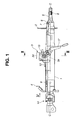
- Fig. 1 is a side view of a shock-absorbing tilt type steering column showing partly a cross section, according to an embodiment of the present invention;
- Fig. 2 is a plan view of an essential part of the shock-absorbing tilt type steering column, according to the embodiment of the present invention;
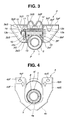
- Fig. 3 is a cross section taken along the lines III-III in Fig. 1;
- Fig. 4 is a front view in the direction IV in Fig. 1;
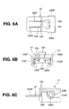
- Fig. 5 shows a
distance bracket 11, in which
Fig. 5A is a plan view,
Fig. 5B is a front view, and
Fig. 5C is a side view; - Fig. 6 shows an energy absorbing mechanism including the
distance bracket 11 and anenergy absorber 12, in which
Fig. 6A is a plan view,
Fig. 6B is a front view, and
Fig. 6C is a side view; and - Fig. 7 is a side view of an essential part of a related art.
-
- In the following, various embodiments of the present invention will be described in detail with reference to the accompanying drawings.
- For ease of understanding, the following description will contain various directional terms, such as, left, right, upper, lower, forward, rearward and the like. However, such terms are to be understood with respect to only a drawing or drawings on which the corresponding part of element is illustrated.
- In addition, some members described in the following embodiment have, if desired, suffixes "F" denoting first and "S" denoting second. With this, each of the members can be properly distinguished from its counterpart. Each of "F" and "S" is to be suffixed to a numeral following the member.
- As is seen in Fig. 1 to Fig. 4, there is provided a
column jacket 1 which is formed through a drawing into a stepped cylinder. Thecolumn jacket 1 defines a rear end side (right in Fig. 1) to which aunit mounting bracket 2 is fixed. Anupper clamp 3 which acts as a support bracket supports substantially a center section of thecolumn jacket 1 to a vehicular body. Thecolumn jacket 1 defines a front end side (left in Fig. 1) which is supported to the vehicular body by means of alower clamp 4. A steeringshaft 5 is inserted into thecolumn jacket 1 concentrically with thecolumn jacket 1. - Like the
column jacket 1, the steeringshaft 5 is formed through the drawing into a stepped cylinder. The steeringshaft 5 defines a rear end side (right in Fig. 1) which is formed with anengagement section 6 for mounting a steering wheel. In the vicinity of theengagement section 6, there is provided abearing 7 which is disposed at the rear end of thecolumn jacket 1 in such a manner as to be interposed between thecolumn jacket 1 and thesteering shaft 5. Arubber bush 8 is interposed between a front end side of thesteering shaft 5 and the front end side of thecolumn jacket 1, in such a manner that thesteering shaft 5 is rotatable about an axis of thecolumn jacket 1. A stopper 9 (nut) abutting on thebearing 7 is fitted to the rear end side of thesteering shaft 5. The front end side of thesteering shaft 5 can connect to an intermediary shaft (not shown) by way of auniversal joint 10. - A shock-absorbing mechanism is adopted into the
upper clamp 3 and thelower clamp 4. - More specifically, as is seen in Fig. 3, the
upper clamp 3 includes a pair of a first side wall 3aF and a second side wall 3aS, a pair of a first front wall 3bF and a second front wall 3bS, and a pair of a first vehicular body fixture 3cF and a second vehicular body fixture 3cS. Theupper clamp 3 can be formed in the following manner: - One metal plate is folded into two separate side walls, that is, the first side wall 3aF and the second side wall 3aS. The first front wall 3bF unites with the first side wall 3aF, while the second front wall 3bS unites with the second side wall 3bS. The first vehicular body fixture 3cF unites with an upper section of the first front wall 3bF, while the second vehicular body fixture 3cS unites with an upper section of the second front wall 3bS. Each of the first vehicular body fixture 3cF and the second vehicular body fixture 3cS faces a vehicular body mounting section (not shown in Fig. 3).
- Moreover, the
upper clamp 3 is formed with a pair of a first reinforcement 3eF and a second reinforcement 3eS. The first reinforcement 3eF is so machined as to reinforce a first fold section defined between the first front wall 3bF and the first vehicular body fixture 3cF, while the second reinforcement 3eS is so machined as to reinforce a second fold section defined between the second front wall 3bS and the second vehicular body fixture 3cS. - With the construction of the
upper clamp 3 described above, varying the upper clamp 3 (in thickness) and the first reinforcement 3eF and the second reinforcement 3eS (in size) can contribute to determination of an allowable load which may be applied to the first front wall 3bF and the second front wall 3bS. Hereinabove, the allowable load is defined as an upper limit. Therefore, an excessive load {greater than the allowable load (upper limit)} caused in a vehicular collision and the like may deform the first front wall 3bF and the second front wall 3bS forward, respectively, relative to the first vehicular body fixture 3cF and the second vehicular body fixture 3cS. - Moreover, the
upper clamp 3 is formed with a first wavy section 3dF and a second wavy section 3dS which are disposed between the first vehicular body fixture 3cF and the second vehicular body fixture 3cS. The first wavy section 3dF and the second wavy section 3dS are formed for the following cause: - A distance between the first side wall 3aF and the second side wall 3aS is formed greater than a predetermined distance, so as to secure a required width for each of the first side wall 3aF and the second side wall 3aS. The first wavy section 3dF and the second wavy section 3dS contribute to correction of the distance (between the first side wall 3aF and the second side wall 3aS) to the predetermined distance.
- Outside the first wavy section 3dF and the second wavy section 3dS, there are defined a first through hole 3gF and a second through hole 3gS for inserting bolts which are used for fixing the
upper clamp 3 to the vehicular body. - The
side wall 3a is formed with an elongate hole 3f for atilt bolt 13. Theside wall 3a is determined in height for the following construction: - Even when the
tilt bolt 13 reaches an uppermost section of the elongate hole 3f, at least a lower end of theside wall 3a can be prevented from protruding downward (in Fig. 3) from a lowermost section P on an outer periphery of thecolumn jacket 1. - In other words, the above description can be interpreted as follows:
- When the
tilt bolt 13 is disposed substantially in the vertical center section of the elongate hole 3f as is seen in Fig. 1, the lower end of theside wall 3a reaches substantially a vertical center of the outer periphery of the column jacket 1 (in other words, on a level with an axial line C-C of the column jacket 1). - Between the first side wall 3aF and the second side wall 3aS, there is interposed a
distance bracket 11 in such a manner as to slide upward and downward. As is seen in Fig. 3 and Fig. 5B, thedistance bracket 11 has a first lower end 11cF and a second lower end 11cS which couple with the upper outer periphery of thecolumn jacket 1 through a welding and the like. As is seen in Fig. 5B, thedistance bracket 11 has a cross section which is a groove wall shaped substantially into an English alphabet "C" turned clockwise by 90° (similar to a Japanese katakana character "" turned counterclockwise by 90°). As is seen in Fig. 5A, an upper side wall of the
distance bracket 11 has a front end {left end in Fig. 5A} formed with anengagement port 11b which is a cutout shaped substantially into an English alphabet "T" turned clockwise by 90°. Theengagement port 11b is defined substantially in the center of the front end. As is seen in Fig. 5C, a right side wall and a left side wall of thedistance bracket 11 are, respectively, formed with a first engagement groove 11aF and a second engagement groove 11aS. Each of the first engagement groove 11aF and the second engagement groove 11aS is shaped substantially into an English alphabet "U" turned clockwise by 90°, and opens rearward {rightward in Fig. 5C}. In addition, thedistance bracket 11 defines a dent which is disposed substantially in a longitudinal middle section in the upper side wall. The dent can increase rigidity of thedistance bracket 11, and opposes a curved bottom section of the English alphabet "U" of each of the first engagement groove 11aF and the second engagement groove 11aS. - The engagement groove 11a is so designed as to disengage from the
tilt bolt 13 only when the excessive load {greater than the allowable load (upper limit)} is applied to thedistance bracket 11 in a forward direction of the vehicle, and not disengage from thetilt bolt 13 when the applied load is not excessive (namely, smaller than or substantially equal to the upper limit). - As is seen in Fig. 6A, Fig. 6B and Fig. 6C, there is provided an
energy absorber 12 which is a metal plate having the following construction: - The
energy absorber 12 is formed with anengagement section 12a shaped substantially into the English alphabet T. Theenergy absorber 12 is disposed in thedistance bracket 11 such that theengagement section 12a can engage with theengagement port 11b. As is seen in Fig. 6B, theenergy absorber 12 has a rear end which has a cross section shaped substantially into an English alphabet "C" turned clockwise by 90° (similar to a Japanese katakana character "energy absorber 12 has a first side wall 12fF and a second side wall 12fS which are formed, respectively, with a first circular hole 12bF and a second circular hole 12bS for inserting therein thetilt bolt 13. As is seen in Fig. 6C, theenergy absorber 12 has substantially a center section bent in such a manner as to form astage 12d, and a front end section extending forward relative to thedistance bracket 11 by a predetermined length. As is seen in Fig. 6A, theengagement section 12a is formed through a punching, leaving a punchedsection 12c. The thus formedengagement section 12a is so formed as to stand (substantially erect) on thestage 12d, as is seen in Fig. 6C. Moreover, there are formed a first indent section 12eF and a second indent section 12eS extending respectively from a right end and a left end of the punchedsection 12c, substantially in parallel with a right side and a left side of theengagement section 12a. - With the above construction of the
energy absorber 12, engaging theengagement section 12a with theengagement port 11b can integrate theenergy absorber 12 with thedistance bracket 11. In sum, the energy absorbing member can be of one piece construction of metal plate, and small in size, thus lowering cost. - As is seen in Fig. 2 and Fig. 3, the
tilt bolt 13 has a first end formed with ahead section 13a, and a second end formed with ascrew section 13b. Thehead section 13a is formed with arotation stopper 13c which engages with the first elongate hole 3fF of the first side wall 3aF of theupper clamp 3. Thetilt bolt 13 may be inserted in the following sequence: - 1. the first elongate hole 3fF of the first side wall 3aF of the
upper clamp 3. - 2. the first engagement groove 11aF of the
distance bracket 11. - 3. the first circular hole 12bF of the
energy absorber 12. - 4. the second circular hole 12bS of the
energy absorber 12. - 5. the second engagement groove 11aS of the
distance bracket 11. - 6. the second elongate hole 3fS of the second side wall 3aS of the
upper clamp 3. -
- Outside the second side wall 3aS (left in Fig. 3), the
screw section 13b is inserted into a tightening plate 16 (for locking the tilt bolt 13) and anut 14. The tighteningplate 16 is formed with arotation stopper 16a engaging with the second elongate hole 3fS. Atilt lever 17 is fixed to thenut 14 through the welding and the like in such a manner as to rotate integrally with thenut 14. - As is seen in Fig. 4, the
lower clamp 4 is a metal plate formed with acutout 4f, leaving anarc coupler 4a coupling (through the welding and the like) with a part of the outer periphery of thecolumn jacket 1 at the front end of thecolumn jacket 1. Thelower clamp 4 has an upper section formed with a first plate 4bF and a second plate 4bS which face a mount section of the vehicular body. For inserting a bolt, the first plate 4bF defines a first through hole 4cF, while the second plate 4bS defines a second through hole 4cS. For greater strength of entire part of thelower clamp 4, there are formed a pair of a first upper flange 4dF and a second upper flange 4dS, and alower flange 4e. Thearc coupler 4a acts as a rotation center (fulcrum) of thecolumn jacket 1 during tilt adjustment. Moreover, thearc coupler 4a is designed in strength such that thecolumn jacket 1 can move in the axial direction when the shock is applied. - Hereinafter described is how shock absorption works with the shock-absorbing tilt type steering column having the construction described above.
- Tilt adjustment of the
column jacket 1 can be carried out in the following manner: - 1. Use the
tilt lever 17 to relax tightening strength caused by the tighteningplate 16 which is disposed on thenut 14's side of thetilt bolt 13. - 2. Turn the
column jacket 1 upward or downward for tilt adjustment, to thereby adjust thecolumn jacket 1 to a predetermined setting position. - 3. Use the
tilt lever 17 again so as to tighten the tighteningplate 16.
In addition, there is shown in Fig. 3 an -
- Hereinabove, the
side wall 3a of theupper clamp 3 is so adjusted in height as to bring about the following operation: - Even when the
tilt bolt 13 moves upward thereby reaching the uppermost section of the elongate hole 3f, the lower end of theside wall 3a does not protrude downward from the lowermost section P on the outer periphery of thecolumn jacket 1. - Although the lowermost section P of the
column jacket 1 may touch the seat occupant's knee or thigh, at least the lower end of theside wall 3a can be preferably prevented from touching the seat occupant's knee or thigh, thus securing a sufficient space above the seat occupant's knee or thigh. - A secondary collision by the seat occupant with the steering wheel may cause the
stopper 9 of thesteering shaft 5 to abut on thebearing 7, thereby applying a load to thecolumn jacket 1 in the axial direction. The thus applied excessive load {greater than the allowable load (upper limit)} may move the pair of the first front wall 3bF (united with the first side wall 3aF) and the second front wall 3bS (united with the second side wall 3aS) by way of thetilt bolt 13. An initial load caused by the seat occupant's collision with the steering wheel can be absorbed by deformation of theupper clamp 3, thereby reducing the initial load at the secondary collision and reducing shock to the seat occupant. - Thereafter, the
distance bracket 11 coupling with thecolumn jacket 1 may move forward relative to theupper clamp 3 in such a manner as to disengage from thetilt bolt 13 by way of the first engagement groove 11aF and the second engagement groove 11aS which are facing rearward. On the other hand, thetilt bolt 13 can remain inserted through theupper clamp 3. - Then, the disengagement of the
distance bracket 11 from thetilt bolt 13 may also move theengagement section 12a (engaging with theengagement port 11b of the distance bracket 11) of theenergy absorber 12, thereby tearing theenergy absorber 12 along the first indent section 12eF and the second indent section 12eS and bending the metal plate between the first indent section 12eF and the second indent section 12eS. - With the above tearing (of the
energy absorber 12 along the first indent section 12eF and the second indent section 12eS) and bending (of the metal plate between the first indent section 12eF and the second indent section 12eS), theenergy absorber 12 made of the metal can thus absorb the excessive load {greater than the allowable load (upper limit)} applied to thesteering shaft 5. - In sum, according to the embodiment of the present invention, even when the
tilt bolt 13 reaches the uppermost section of the elongate hole 3f formed in theside wall 3a of theupper clamp 3, at least the lower end of theside wall 3a can be prevented from protruding downward (in Fig. 3) from the lowermost section P on the outer periphery of thecolumn jacket 1. Moreover, according to the embodiment of the present invention, theenergy absorber 12 is interposed between an upper side of thecolumn jacket 1 and the vehicle mounting section. With the above two features described in the embodiment of the present invention, the seat occupant's knee or thigh can be prevented from touching the lower section of theupper clamp 3, thus preventing any injury to the seat occupant's knee or thigh when theenergy absorber 12 works. - Although the present invention has been described above by reference to certain embodiments, the present invention is not limited to the embodiments described above. Modifications and variations of the embodiments described above will occur to those skilled in the art, in light of the above teachings.
- More specifically, according to the embodiment of the present invention, the
energy absorber 12 is so constituted as to absorb the energy by both tearing (theenergy absorber 12 along the first indent section 12eF and the second indent section 12eS) and bending (the metal plate between the first indent section 12eF and the second indent section 12eS). However, theenergy absorber 12 can be the one that takes only one of the tearing and the bending of the metal plate. - The entire contents of basic Japanese Patent Application No. P2001-324426 (filed on October 23, 2001 in Japan) from which priority is claimed is incorporated herein by reference, in order to take some protection against mis-translation or omitted portions.
- The scope of the present invention is defined with reference to the following claims.
Claims (19)
- A shock-absorbing tilt type steering column, comprising:1) a column jacket having a lowermost section, a space being defined above the column jacket;2) a coupler;3) an upper clamp including a pair of a first side wall and a second side wall formed respectively with a first hole and a second hole for tilting the shock-absorbing tilt type steering column, the coupler being inserted into the first hole and the second hole, the space defined above the column jacket being defined in the upper clamp, each of the pair of the first side wall and the second side wall having such a height that a lower end thereof is disposed substantially on a level with or higher than the lowermost section of the column jacket when the coupler is disposed in an uppermost position of each of the first hole and the second hole;4) a distance bracket sandwiched between the first side wall and the second side wall of the upper clamp in such a manner as to move upward and downward, the distance bracket coupling with the column jacket, the distance bracket being adapted to engage with the coupler in such a manner as to be disengageable from the coupler in a forward direction of a vehicle when a load greater than an upper limit is applied to the distance bracket axially in a direction along the column jacket, the distance bracket being disposed in the space with the lower end of each of the first side wall and the second side wall disposed substantially on the level with or higher than the lowermost section of the column jacket; and5) an energy absorber interposed between the distance bracket and the coupler.
- The shock-absorbing tilt type steering column as claimed in claim 1, wherein the energy absorber is a metal plate comprising:a rear end section adapted to engage with the coupler, anda front end section extending forward by a first predetermined length from the distance bracket; andthe energy absorber is partly bent in such a manner as to form an engagement section which stands upward by a second predetermined length and engages with the distance bracket.
- The shock-absorbing tilt type steering column as claimed in claim 2, wherein
the energy absorber is formed with a first indent section and a second indent section extending substantially in parallel with the engagement section standing upward. - The shock-absorbing tilt type steering column as claimed in claim 1, whereinthe upper clamp further includes a first front wall united with the first side wall and a second front wall united with the second side wall,the upper clamp further includes a first fixture united with the first front wall and a second fixture united with the second front wall, the first fixture and the second fixture being fixed to the vehicle, the first front wall and the second front wall being bent, respectively, from the first fixture and the second fixture, andthe first front wall and the second front wall are deformable in the forward direction of the vehicle when receiving the load greater than the upper limit.
- The shock-absorbing tilt type steering column as claimed in claim 1, whereinthe coupler is a tilt bolt for tilting the shock-absorbing tilt type steering column, andeach of the first hole and a second hole is elongated substantially upward and downward.
- The shock-absorbing tilt type steering column as claimed in claim 5, wherein
the upper clamp further includes a pair of a first reinforcement and a second reinforcement which are, respectively, so machined as to reinforce a first fold section defined between the first front wall and the first fixture and a second fold section defined between the second front wall and the second fixture. - The shock-absorbing tilt type steering column as claimed in claim 6, wherein
the upper clamp further includes a first wavy section and a second wavy section which are disposed between the first fixture and the second fixture. - The shock-absorbing tilt type steering column as claimed in claim 7, whereinthe distance bracket has a first lower end and a second lower end which couple with an upper outer periphery of the column jacket through a welding and the like,the distance bracket has a cross section which is a groove wall shaped substantially into an English alphabet C,an upper side wall of the distance bracket has a front end formed with an engagement port which is a cutout shaped substantially into an English alphabet T, the engagement port being defined substantially in a center of the upper side wall of the distance bracket,a right side wall and a left side wall of the distance bracket are, respectively, formed with a first engagement groove and a second engagement groove, each of the first engagement groove and the second engagement groove being shaped substantially into an English alphabet U, and opening rearward, andthe distance bracket defines a dent which is disposed substantially in a longitudinal middle section in the upper side wall, the dent increasing a rigidity of the distance bracket, and opposing a curved bottom section of the English alphabet U of each of the first engagement groove and the second engagement groove.
- The shock-absorbing tilt type steering column as claimed in claim 8, wherein
the first engagement groove and the second engagement groove of the distance bracket are so constituted as to disengage from the tilt bolt only when the load greater than the upper limit is applied to the distance bracket in the forward direction of the vehicle, and not disengage from the tilt bolt when the applied load is smaller than or substantially equal to the upper limit. - The shock-absorbing tilt type steering column as claimed in claim 9, wherein
the engagement section of the energy absorber is shaped substantially into an English alphabet T, the energy absorber being disposed in the distance bracket such that the engagement section engages with the engagement port of the distance bracket. - The shock-absorbing tilt type steering column as claimed in claim 10, whereinthe energy absorber has a rear end which has a cross section shaped substantially into an English alphabet C,the energy absorber has a first side wall and a second side wall which are formed, respectively, with a first circular hole and a second circular hole for inserting therein the tilt bolt,the energy absorber has substantially a center section bent in such a manner as to form a stage, and a front end section extending forward relative to the distance bracket by a predetermined length,the engagement section of the energy absorber is formed through a punching, leaving a punched section, and the thus formed engagement section is so formed as to stand substantially erect on the stage,the first indent section and the second indent section extend respectively from a right end and a left end of the punched section, substantially in parallel with a right side and a left side of the engagement section.
- The shock-absorbing tilt type steering column as claimed in claim 11, wherein
the engagement section of the energy absorber adapted to engage with the engagement port of the distance bracket integrates the energy absorber with the distance bracket, resulting in one piece construction of the metal plate. - The shock-absorbing tilt type steering column as claimed in claim 12, wherein the distance bracket has the following construction:when the load greater than the upper limit is applied to the distance bracket axially in the direction along the column jacket, the distance bracket coupling with the column jacket moves forward relative to the upper clamp in such a manner as to disengage from the tilt bolt by way of the first engagement groove and the second engagement groove which are facing rearward while the tilt bolt remains inserted through the upper clamp.
- The shock-absorbing tilt type steering column as claimed in claim 13, wherein
the energy absorber has the following construction:the disengagement of the distance bracket from the tilt bolt moves the engagement section of the energy absorber, thereby causing at least one of the following:tearing the energy absorber along the first indent section and the second indent section, andbending the metal plate between the first indent section and the second indent section. - A shock-absorbing steering system, comprising:1) a column jacket shaped substantially into a cylinder having a lowermost section, the column jacket defining a center section and a front end side, a space being defined above the column jacket;2) a coupler;3) an upper clamp disposed in the center section of the column jacket, the upper clamp including a pair of a first side wall and a second side wall formed respectively with a first hole and a second hole, the coupler being inserted into the first hole and the second hole, the space defined above the column jacket being defined in the upper clamp, each of the pair of the first side wall and the second side wall having such a height that a lower end thereof is disposed substantially on a level with or higher than the lowermost section of the column jacket when the coupler is disposed in an uppermost position of each of the first hole and the second hole;4) a distance bracket sandwiched between the first side wall and the second side wall of the upper clamp in such a manner as to move upward and downward, the distance bracket coupling with the column jacket, the distance bracket being adapted to engage with the coupler in such a manner as to be disengageable from the coupler in a forward direction of a vehicle when a load greater than an upper limit is applied to the distance bracket axially in a direction along the column jacket, the distance bracket being disposed in the space with the lower end of each of the first side wall and the second side wall disposed substantially on the level with or higher than the lowermost section of the column jacket;5) an energy absorber interposed between the distance bracket and the coupler; and6) a lower clamp disposed on the front end side of the column jacket.
- The shock-absorbing steering system as claimed in claim 15, whereinthe energy absorber is a metal plate comprising:a rear end section adapted to engage with the coupler, anda front end section extending forward by a first predetermined length from the distance bracket; andthe energy absorber is partly bent in such a manner as to form an engagement section which stands upward by a second predetermined length and engages with the distance bracket.
- The shock-absorbing steering system as claimed in claim 16, wherein
the energy absorber is formed with a first indent section and a second indent section extending substantially in parallel with the engagement section standing upward. - The shock-absorbing steering system as claimed in claim 15, whereinthe coupler is a tilt bolt for tilting the shock-absorbing tilt type steering column, andeach of the first hole and a second hole is elongated substantially upward and downward.
- The shock-absorbing steering system as claimed in claim 15, whereinthe lower clamp is a metal plate formed with a cutout, leaving an arc coupler coupling with a part of an outer periphery of the column jacket,the lower clamp has an upper section formed with a first plate and a second plate which face a mount section of a vehicular body,the first plate defines a first through hole, while the second plate defines a second through hole, andthe lower clamp is formed with a pair of a first upper flange and a second upper flange, and a lower flange.
Applications Claiming Priority (2)
| Application Number | Priority Date | Filing Date | Title |
|---|---|---|---|
| JP2001324426 | 2001-10-23 | ||
| JP2001324426A JP2003127874A (en) | 2001-10-23 | 2001-10-23 | Shock absorbing tilt steering column |
Publications (1)
| Publication Number | Publication Date |
|---|---|
| EP1306286A1 true EP1306286A1 (en) | 2003-05-02 |
Family
ID=19141156
Family Applications (1)
| Application Number | Title | Priority Date | Filing Date |
|---|---|---|---|
| EP02023691A Withdrawn EP1306286A1 (en) | 2001-10-23 | 2002-10-22 | Shock-absorbing tilt type steering column |
Country Status (3)
| Country | Link |
|---|---|
| US (1) | US6799779B2 (en) |
| EP (1) | EP1306286A1 (en) |
| JP (1) | JP2003127874A (en) |
Families Citing this family (38)
| Publication number | Priority date | Publication date | Assignee | Title |
|---|---|---|---|---|
| JP2003160051A (en) * | 2001-09-14 | 2003-06-03 | Nsk Ltd | Shock absorbing type steering column device for vehicle |
| US6814374B2 (en) * | 2002-06-28 | 2004-11-09 | Delphi Technologies, Inc. | Steering column with foamed in-place structure |
| JPWO2004005109A1 (en) * | 2002-07-02 | 2005-11-04 | 日本精工株式会社 | Shock absorbing steering column device for vehicles |
| JP4179049B2 (en) * | 2002-07-16 | 2008-11-12 | 日本精工株式会社 | Position-adjustable steering column device |
| JP2004155268A (en) | 2002-11-05 | 2004-06-03 | Nsk Ltd | Telescopic steering column device |
| JP4062082B2 (en) * | 2002-12-12 | 2008-03-19 | 日本精工株式会社 | Steering column device |
| US7077432B2 (en) * | 2003-09-30 | 2006-07-18 | Delphi Technologies, Inc. | Steering column assembly having break-away device |
| US7267370B2 (en) * | 2004-03-11 | 2007-09-11 | Delphi Technologies, Inc. | Frequency and stiffness enhancement mechanization |
| DE102005034952B3 (en) * | 2005-07-22 | 2007-02-22 | Thyssenkrupp Automotive Ag | Adjustable steering column for a motor vehicle |
| DE102005056308B3 (en) * | 2005-11-24 | 2007-03-29 | Thyssenkrupp Presta Ag | Adjustable steering column for motor vehicle, has adjusting unit adjustable opposite to retaining unit to adjust position of column in opened condition of fixing device, and blocking unit connected with retaining unit |
| US7611165B2 (en) * | 2006-06-23 | 2009-11-03 | Delphi Technologies, Inc. | Adjustable steering column assembly having an attached instrument cluster |
| US7819220B2 (en) * | 2006-07-28 | 2010-10-26 | Polaris Industries Inc. | Side-by-side ATV |
| US8827028B2 (en) * | 2006-07-28 | 2014-09-09 | Polaris Industries Inc. | Side-by-side ATV |
| KR100836370B1 (en) * | 2006-12-15 | 2008-06-09 | 현대자동차주식회사 | Tilt lever structure of steering column |
| US7795602B2 (en) * | 2007-03-16 | 2010-09-14 | Polaris Industries Inc. | Vehicle |
| US7871106B2 (en) * | 2007-03-16 | 2011-01-18 | Polaris Industries Inc. | Method and apparatus related to transportability of a vehicle |
| US8029021B2 (en) | 2007-03-16 | 2011-10-04 | Polaris Industries Inc. | Vehicle |
| WO2008115459A1 (en) * | 2007-03-16 | 2008-09-25 | Polaris Industries Inc. | Utility vehicle having modular components |
| US8167072B2 (en) * | 2007-03-16 | 2012-05-01 | Polaris Industries Inc. | Vehicle with space utilization |
| US7717495B2 (en) * | 2007-03-16 | 2010-05-18 | Polaris Industries, Inc. | Vehicle with space utilization |
| KR100975197B1 (en) * | 2007-07-19 | 2010-08-10 | 현대자동차주식회사 | tilt device of steering column |
| JP5277023B2 (en) * | 2009-02-27 | 2013-08-28 | 富士機工株式会社 | Steering column device |
| DE102009021579A1 (en) * | 2009-05-15 | 2010-11-18 | Thyssenkrupp Presta Ag | Steering column for a motor vehicle |
| US8998253B2 (en) | 2012-03-30 | 2015-04-07 | Polaris Industries Inc. | Folding cab frame |
| US9623912B2 (en) | 2012-09-20 | 2017-04-18 | Polaris Industries Inc. | Utility vehicle |
| US9440671B2 (en) | 2012-09-20 | 2016-09-13 | Polaris Industries Inc. | Vehicle |
| US9592782B2 (en) | 2012-09-20 | 2017-03-14 | Polaris Industries Inc. | Vehicle |
| GB201313221D0 (en) * | 2013-07-24 | 2013-09-04 | Trw Ltd | A telescopic assembly |
| CN104828126B (en) * | 2014-05-27 | 2017-06-06 | 北汽福田汽车股份有限公司 | Steering column crumple energy-absorbing component for vehicle and the automobile with it |
| AU2016265556B2 (en) | 2015-05-15 | 2019-05-02 | Polaris Industries Inc. | Utility vehicle |
| US9884647B2 (en) | 2015-12-10 | 2018-02-06 | Polaris Industries Inc. | Utility vehicle |
| US10960941B2 (en) | 2018-01-10 | 2021-03-30 | Polaris Industries Inc. | Vehicle |
| US10793181B2 (en) | 2018-02-13 | 2020-10-06 | Polaris Industries Inc. | All-terrain vehicle |
| US10946736B2 (en) | 2018-06-05 | 2021-03-16 | Polaris Industries Inc. | All-terrain vehicle |
| WO2020213546A1 (en) * | 2019-04-18 | 2020-10-22 | 日本精工株式会社 | Steering device |
| US11260803B2 (en) | 2019-07-26 | 2022-03-01 | Polaris Industries Inc. | Audio system for a utility vehicle |
| US11718240B2 (en) | 2019-12-20 | 2023-08-08 | Polaris Industries Inc. | All-terrain vehicle |
| USD937710S1 (en) | 2020-07-24 | 2021-12-07 | Polaris Industries Inc. | All-terrain vehicle |
Citations (5)
| Publication number | Priority date | Publication date | Assignee | Title |
|---|---|---|---|---|
| US4901592A (en) * | 1988-06-17 | 1990-02-20 | Nippon Seiko Kabushiki Kaisha | Shock absorbing steering apparatus |
| EP0928733A2 (en) * | 1997-12-26 | 1999-07-14 | Fuji Kiko Company Limited | Steering column for automotive vehicle |
| FR2775648A1 (en) * | 1998-03-03 | 1999-09-10 | Lemforder Nacam Sa | Automobile steering column double coil energy absorber |
| FR2784343A1 (en) * | 1998-10-07 | 2000-04-14 | Ecia Equip Composants Ind Auto | POSITION ADJUSTABLE STEERING COLUMN ASSEMBLY, FOR EXAMPLE FOR A MOTOR VEHICLE |
| EP1223096A1 (en) * | 2001-01-11 | 2002-07-17 | FUJI KIKO Co., Ltd. | Steering column assembly for a vehicle |
Family Cites Families (8)
| Publication number | Priority date | Publication date | Assignee | Title |
|---|---|---|---|---|
| JP3471061B2 (en) | 1994-02-04 | 2003-11-25 | 光洋精工株式会社 | Shock absorbing steering device |
| JPH08295251A (en) | 1995-04-26 | 1996-11-12 | Nippon Seiko Kk | Shock absorbing steering column unit |
| JP2978788B2 (en) | 1995-10-20 | 1999-11-15 | 富士機工株式会社 | Automotive steering column |
| DE19617561C1 (en) * | 1996-05-02 | 1997-09-25 | Daimler Benz Ag | Adjustable telescopic automotive steering column |
| JP2000103339A (en) * | 1998-07-30 | 2000-04-11 | Nsk Ltd | Steering column supporting device |
| DE60133331T3 (en) * | 2000-02-15 | 2012-12-06 | Nsk Ltd. | Steering for an automobile |
| JP4667676B2 (en) * | 2000-09-19 | 2011-04-13 | エヌエスケー ステアリング システムズ ヨーロッパ リミテッド | Vehicle steering column control device |
| US6652002B2 (en) * | 2001-10-19 | 2003-11-25 | Delphi Technologies, Inc. | Crash responsive energy absorbing device for a steering column |
-
2001
- 2001-10-23 JP JP2001324426A patent/JP2003127874A/en active Pending
-
2002
- 2002-10-22 EP EP02023691A patent/EP1306286A1/en not_active Withdrawn
- 2002-10-22 US US10/277,096 patent/US6799779B2/en not_active Expired - Fee Related
Patent Citations (5)
| Publication number | Priority date | Publication date | Assignee | Title |
|---|---|---|---|---|
| US4901592A (en) * | 1988-06-17 | 1990-02-20 | Nippon Seiko Kabushiki Kaisha | Shock absorbing steering apparatus |
| EP0928733A2 (en) * | 1997-12-26 | 1999-07-14 | Fuji Kiko Company Limited | Steering column for automotive vehicle |
| FR2775648A1 (en) * | 1998-03-03 | 1999-09-10 | Lemforder Nacam Sa | Automobile steering column double coil energy absorber |
| FR2784343A1 (en) * | 1998-10-07 | 2000-04-14 | Ecia Equip Composants Ind Auto | POSITION ADJUSTABLE STEERING COLUMN ASSEMBLY, FOR EXAMPLE FOR A MOTOR VEHICLE |
| EP1223096A1 (en) * | 2001-01-11 | 2002-07-17 | FUJI KIKO Co., Ltd. | Steering column assembly for a vehicle |
Also Published As
| Publication number | Publication date |
|---|---|
| JP2003127874A (en) | 2003-05-08 |
| US6799779B2 (en) | 2004-10-05 |
| US20030085560A1 (en) | 2003-05-08 |
Similar Documents
| Publication | Publication Date | Title |
|---|---|---|
| EP1306286A1 (en) | Shock-absorbing tilt type steering column | |
| EP2923921B1 (en) | Steering device | |
| US5547221A (en) | Energy absorbing member for shock absorbing steering column apparatus | |
| EP1245472B1 (en) | Steering apparatus | |
| WO2012132505A1 (en) | Steering column device | |
| JPH0728048Y2 (en) | Shock absorption type steering column device | |
| JPH07232649A (en) | Steering device for vehicle | |
| US5209135A (en) | Impact absorbing type steering column device | |
| US7125046B2 (en) | Shock absorbing steering column device for vehicle | |
| JP2513633Y2 (en) | Shock absorption type steering column device | |
| JPH09272448A (en) | Shock absorbing type steering column device | |
| JPH07117685A (en) | Steering device for vehicle | |
| JPH07117686A (en) | Energy absorbing steering device | |
| JPH0924843A (en) | Shock absorbing-type steering device | |
| JP4207799B2 (en) | Shock absorbing steering column device | |
| JP3389767B2 (en) | Shock absorbing steering column device | |
| JPH08295251A (en) | Shock absorbing steering column unit | |
| JPH0958485A (en) | Steering column supporting device | |
| US5737970A (en) | Safety steering column for a motor vehicle | |
| KR20140065844A (en) | Steering column device of vehicles | |
| JP4258274B2 (en) | Shock absorbing steering column device for vehicles | |
| JP2001315649A (en) | Steering column support device | |
| US10308276B2 (en) | Variable steering angle steering device | |
| JP2599596Y2 (en) | Shock absorbing steering system with tilt mechanism | |
| JP3427597B2 (en) | Tilt type steering device |
Legal Events
| Date | Code | Title | Description |
|---|---|---|---|
| PUAI | Public reference made under article 153(3) epc to a published international application that has entered the european phase |
Free format text: ORIGINAL CODE: 0009012 |
|
| 17P | Request for examination filed |
Effective date: 20021022 |
|
| AK | Designated contracting states |
Designated state(s): AT BE BG CH CY CZ DE DK EE ES FI FR GB GR IE IT LI LU MC NL PT SE SK TR |
|
| AX | Request for extension of the european patent |
Extension state: AL LT LV MK RO SI |
|
| 17Q | First examination report despatched |
Effective date: 20031027 |
|
| AKX | Designation fees paid |
Designated state(s): DE FR GB |
|
| STAA | Information on the status of an ep patent application or granted ep patent |
Free format text: STATUS: THE APPLICATION IS DEEMED TO BE WITHDRAWN |
|
| 18D | Application deemed to be withdrawn |
Effective date: 20040309 |