EP1311041A2 - Spark plug and combustion chamber arrangement - Google Patents
Spark plug and combustion chamber arrangement Download PDFInfo
- Publication number
- EP1311041A2 EP1311041A2 EP02021527A EP02021527A EP1311041A2 EP 1311041 A2 EP1311041 A2 EP 1311041A2 EP 02021527 A EP02021527 A EP 02021527A EP 02021527 A EP02021527 A EP 02021527A EP 1311041 A2 EP1311041 A2 EP 1311041A2
- Authority
- EP
- European Patent Office
- Prior art keywords
- spark plug
- electrode
- ground electrode
- spark
- mixture
- Prior art date
- Legal status (The legal status is an assumption and is not a legal conclusion. Google has not performed a legal analysis and makes no representation as to the accuracy of the status listed.)
- Withdrawn
Links
Images


Classifications
-
- F—MECHANICAL ENGINEERING; LIGHTING; HEATING; WEAPONS; BLASTING
- F02—COMBUSTION ENGINES; HOT-GAS OR COMBUSTION-PRODUCT ENGINE PLANTS
- F02P—IGNITION, OTHER THAN COMPRESSION IGNITION, FOR INTERNAL-COMBUSTION ENGINES; TESTING OF IGNITION TIMING IN COMPRESSION-IGNITION ENGINES
- F02P13/00—Sparking plugs structurally combined with other parts of internal-combustion engines
-
- H—ELECTRICITY
- H01—ELECTRIC ELEMENTS
- H01T—SPARK GAPS; OVERVOLTAGE ARRESTERS USING SPARK GAPS; SPARKING PLUGS; CORONA DEVICES; GENERATING IONS TO BE INTRODUCED INTO NON-ENCLOSED GASES
- H01T13/00—Sparking plugs
- H01T13/20—Sparking plugs characterised by features of the electrodes or insulation
- H01T13/32—Sparking plugs characterised by features of the electrodes or insulation characterised by features of the earthed electrode
-
- H—ELECTRICITY
- H01—ELECTRIC ELEMENTS
- H01T—SPARK GAPS; OVERVOLTAGE ARRESTERS USING SPARK GAPS; SPARKING PLUGS; CORONA DEVICES; GENERATING IONS TO BE INTRODUCED INTO NON-ENCLOSED GASES
- H01T13/00—Sparking plugs
- H01T13/20—Sparking plugs characterised by features of the electrodes or insulation
- H01T13/39—Selection of materials for electrodes
Definitions
- the present invention relates to a spark plug and a Combustion chamber arrangement with a spark plug and an injection valve.
- the problem underlying the present invention generally consists of the poor installation tolerance the spark plug with regard to the sensitivity of the Spark position to improve the injection jet.
- spark plug according to the invention with the features of the claim 1 and the combustion chamber arrangement with the features according to claim 16 point over the known approach the advantage that the installation depth of the spark plug no longer exactly to the position of the neighboring injection jets must be coordinated.
- the idea on which the present invention is based exists in that the center and / or the ground electrode a feed area for feeding the combustible mixture to the spark gap between the center electrode and the Has ground electrode.
- the present invention provides a combustion chamber arrangement, where the spark plug and one with at least one Pair of injection holes provided to each other are arranged so that the injected accordingly Mixture jets flank the spark plug radially and the center of gravity of the mixture beam above the Spark gap between the center electrode and the ground electrode the spark plug is in place.
- the feed area is as at least one through hole, through slot, recessed passage area or the like in the amount of Spark gap for increased accessibility of the mixture trained to spark gap in the ground electrode.
- the ground electrode is designed as a roof-shaped electrode.
- the ground electrode is formed as a fork-shaped electrode, which which surrounds, in particular pin-shaped, central electrode.
- the ground electrode is as at least one stepped electrode for an overlap of the center electrode and / or the insulator educated.
- the ground electrode is as at least one bracket above the combustion chamber side Surface of the center electrode formed.
- the ground electrode is from at least two parallel to each other spaced electrodes formed.
- the ground electrode is approximately ring-shaped and encloses the, in particular step-shaped, center electrode or the insulator.
- the ring-shaped ground electrode is attached to the housing in particular by means of a carrier device.
- the carrier device can also have through bores, through slots, recessed through areas or the like at the height of the spark gap.
- the Spark plug can be installed in such a way that the ground electrode with respect to the main flow direction of the mixture arranged between the injection valve and the center electrode is.
- the The spark plug can be installed so that the center electrode with respect to the main flow direction of the mixture arranged between the injection valve and the ground electrode is.
- the center electrode is curved outwards.
- the Center electrode a through hole, a through slot, a recessed passage area or the like for increased accessibility of the mixture to the spark gap at the height of the spark gap.
- the Cross section of the center and / or ground electrodes round, square, rectangular, triangular or the like.
- the feed area is as a deflection area attached to the ground electrode at the height of the spark gap for increased accessibility of the mixture trained to the spark gap.
- the Angle between the two injected mixture jets through the injection valve preferably 30 ° to 60 °.
- the The axes of the spark plug and the injector are sharp Angles with each other.
- the Injector has a hemispherical head in which several pairs of injection holes are provided, wherein the angle between the beam levels of two corresponding ones Injection holes of assigned pairs of rays preferably is between 25 ° and 30 °.
- FIG. 1a and 1b show a bottom and front view, partly in section, a spark plug 1 according to a first Embodiment of the present invention.
- an insulator 4 is arranged, which is advantageous the rotationally symmetrical axes of the housing 2 and the insulator 4 are congruent.
- the isolator 4 is a preferably rod-shaped inner conductor arrangement with a connecting bolt 11 (see FIGS. 12 and 13), one current-limiting resistor 12 and a coated Contact pin 13 and a center electrode 5 arranged, which, for example, from a special alloy, platinum or the like, is made.
- the arranged in the insulator 4 Components serve to transmit the voltage from the connecting bolt 11 to the center electrode 5.
- a breathing volume 3 is provided between the housing 2 and the insulator 4, which is made, for example consists of a ceramic.
- the connecting bolt 11 is preferably made of steel. Within of the insulator 4, the connecting bolts 11 and the center electrode 5 in a conductive special melt, preferably absolutely tight, anchored.
- the isolator will together with a sealing ring and, for example, a crimp ring inserted into the steel candle housing 2 and through a special process crimped under high pressure and shrunk.
- the spark plug 1 also has a ground electrode 6 which welded to the housing 2 of the spark plug 1, for example is.
- the ground electrode 6 also exists, for example made of a special alloy.
- the ground electrode 6 according to the first embodiment of the present Invention hook-shaped or roof-shaped, the Ground electrode 6 covers the center electrode 5.
- the ground electrode 6 has one parallel to the axis of the spark plug 1 extending section 6a, which is welded to the housing 2 and a roof section running transversely to this axis 6b.
- the ground electrode 6 preferably has a height the spark gap between the surface of the combustion chamber Center electrode 5 and the corresponding opposite Surface of the ground electrode 6 at least one bore 8, one Slot, a recess or the like.
- an injection valve in the combustion chamber 20 which is preferably a hemispherical Head 21 with a plurality of injection holes 22, 22 '; 23 23 '(see Figs. 16 and 17). That from the injection valve 20 flowing mixture is in the figures by the Center of gravity of the respective injection jet 25 representative shown.
- the ground electrode 6 can also consist of two parallel to each other spaced electrodes can be formed to the mixture access to ensure spark gap a.
- the distance a is the Center electrode 5 to ground electrode 6 in the axial direction much smaller than the distance b between the insulator 4 and the one running parallel to the axis of the spark plug 1 Section 6a of the ground electrode 6. Ignition thus takes place or an ignition of the mixture only on the Spark gap a, if the distance b is larger than the necessary one Firing interval is selected.
- the center electrode 5 is in Compared to insulator 4, it extends and protrudes on the combustion chamber side out.
- the spark gap a as far as possible outside the To place candle housing 2, insofar as it consists of thermal and manufacturing reasons is justifiable. This allows different installation tolerances of the spark gap, related to the respective neighboring injection jets, in engines with multiple cylinders are balanced and there is a tolerance insensitivity of the spark gap with regard to different installation depths of the spark plug 1 in the individual cylinders.
- the center electrode 5 are exposed, i.e. without being surrounded by the insulator 4 his.
- Fig. 2 shows a front view in partially sectioned Representation of a spark plug 1 according to a second embodiment of the present invention.
- the center electrode 5 preferably has in this embodiment the shape of a pin that axially on the combustion chamber side End of the contact pin 13 is attached.
- the center electrode 5 is formed from platinum and by means of a Welding method attached to the contact pin 13.
- the Center electrode 5 can ensure sufficient mixture access to the spark gap between the center electrode 5 and the ground electrode 6 of two ground electrodes guided in parallel or from a bifurcated ground electrode 6, such as 2 can be flanked. In this case ignition both in the axial direction over the spark gap a between the contact pin 13 and the ground electrode 6 as well as in the radial direction over the spark gap b between the center electrode 5 and the ground electrode 6th
- ground electrode 6 The free area of the two ground electrodes in parallel or the forked ground electrode serves one Feed area for feeding the combustible mixture to the respective spark gap.
- the ground electrode 6 in turn bores, slots, recesses or the like for a mixture supply aid.
- Fig. 3 is a third embodiment of a spark plug 1, in which the ground electrode 6 is such is designed stepped that they the center electrode 5 and the insulator face to form a certain one Distance covered. With such training it happens in the axial direction above that marked in Fig. 3 Spark gap a, in the radial direction over the spark gap b and additionally over the spark gap c between the Insulator 4 and the overhang portion 6c of the ground electrode 6 to an ignition process.
- the ground electrode 6 preferably has the height of the respective one Spark gap a hole 8, a slot, a Recess or the like so that regardless of the Installation position a sufficient mixture flow to the corresponding Spark gap is guaranteed.
- the center electrode 5 in the amount of the spark gap b and c also a bore 10, a slot, a recess or the like for sufficient access to the mixture to the spark gap b or c.
- the distance d between the parallel spaced Portions of the insulator 4 and the ground electrode 6 is preferably chosen to be somewhat larger than the distances or spark gaps a, b and c. So it comes down to the route d no ignition or no ignition process.
- ground electrodes for example at regular angular intervals, can be arranged around the center electrode 5, all of them for improved mixture accessibility Bores 8, slots, recesses or the like exhibit.
- An advantage of such a design symmetry consists in the large tolerance in the installation direction the spark plug 1.
- the ignition takes place in the radial direction to the center electrode 5 over the spark gap a and in axial Direction to the isolator 4 over the spark gap b.
- the isolator 4 is preferably made of ceramic or the like.
- a fifth embodiment of the present invention is shown in Figs. 5a and 5b.
- the ground electrode 6 is fork-shaped and at least partially surrounds the center electrode 5. This extends the range of the spark gap.
- the one that does not enclose the forked ground electrode 6 The area of the fork electrode serves to feed the flammable mixture to the corresponding spark gap.
- the fork-shaped ground electrode 6 is in turn with a bore 8, a slot, a recess or the like preferably formed at the level of the spark position.
- the cross section of the forks can be rectangular, square, be round, triangular or the like. this applies analogously for the electrode cross sections of the other exemplary embodiments.
- the center electrode surrounded by the fork-shaped ground electrode 6 5 is opposite the insulator 4 on the combustion chamber side extended. Inflammation occurs radially Direction across the spark gap a between the ground electrode 6 and the center electrode 5 and in the axial direction over the spark gap b between the ground electrode 6 and the isolator 4.
- the ground electrode consists of two parallel to each other guided electrodes, which passes the center electrode 5 and to both the center electrode 5 and Ignite the front surface of the insulator 4.
- the two electrodes are preferably point symmetrical with respect to the axis of the Center electrode 5 to the housing 2 of the spark plug 1 or another ground electrode welded on.
- the intermediate area 8 between the two electrodes serves an improved Accessibility of the combustible mixture to the spark gap.
- the two ground electrodes can also be on the same side the center electrode 5 on the housing 2 of the spark plug 1, i.e. axisymmetric, be attached.
- the ground electrodes can also be used each as a bracket on both sides of the center electrode 5 are attached to the housing 2 of the spark plug 1. Through an arcuate bulge in the area of the central electrode 5, the ground electrodes can preferably additionally adapted to the circular cross section of the center electrode 5 become.
- Ignition takes place in the radial direction to the center electrode 5 and in the axial direction of the isolator 4.
- the cross-section of the electrodes can, as previously mentioned, square, round, square, triangular or the like his.
- narrower brackets spaced parallel to each other be, for example, one-sided on the housing 2 of the Spark plug 1 are welded.
- the ground electrode 6 formed in a ring and encloses the center electrode 5, which preferably over the end face the insulator 4 is extended and from the insulator 4 protrudes on the combustion chamber side.
- the ring-shaped ground electrode 6 is preferably by means of oppositely arranged ring carriers 7 on the housing 2 of the spark plug 1 welded.
- the ground electrode 6 has advantageous in the amount of the spark gap a or b holes 8, slots or the like, preferably in the ring carriers 7 for better mixture access to the spark gap are provided.
- the ring bearer of the ring-shaped Ground electrode 6 are preferably in the installed state directed parallel to the direction of flow of the combustible mixture, thus feeding the mixture to the spark gap not be disturbed by the wearer and not the danger there may be thermal shocks.
- the ignition takes place in the radial direction via the Spark gap a to the center electrode 5 and in the axial direction over the spark gap b to the ceramic insulator 4.
- Fig. 9 shows a front view, partly in section, one Spark plug 1 according to a ninth embodiment of the present invention.
- the center electrode 5 has one Head on, the diameter of which is the outer diameter of the insulator 4 corresponds to the contact surface.
- the housing 2 the spark plug 1 takes over according to this embodiment the function of the ground electrode 6, due to the withdrawn Ground electrode 6 of the spark from the nail head the center electrode 5 via the insulator 4 to the ground electrode 6 or housing 2 migrates. Without a nail-shaped head the spark would go directly from the center electrode 5 to the ground electrode 6 and furrow digging in the isolator 4 have as a consequence. This in turn could cause the engine to stall due to an insufficient amount of fuel mixture.
- the seat for the insulator 4 can be in the direction of the connecting bolt 11 to be moved to an additional breathing space 3 to win for hotter spark plug variants.
- FIG. 10 is a spark plug 1 according to a tenth embodiment of the present invention, wherein the center electrode 5 analogous to the ninth embodiment is formed like a nail head.
- the center electrode 5 is preferably a ring-shaped one Ground electrode 6 is provided, which by means of ring carriers 7 on Housing 2 of the spark plug 1 is attached.
- the distance between the ring-shaped ground electrode 6 and the ceramic insulator 4 should be kept as small as possible, however be tolerated that the different thermal expansions of the insulator 4 and the ring-shaped ground electrode 6 are taken into account.
- the ring carrier 7 of the annular ground electrode 6 can for better accessibility of the mixture to the spark gap Bores, slots, recesses or the like exhibit. Furthermore, the ground electrode 6 can also be used as Half ring with one or two ring carriers, the half ring preferably facing the flow Side.
- a rotational symmetry, a shunt insensitivity, is thus advantageous and created a variable installation depth.
- FIG 11 is a front view, partly in section, a spark plug 1 according to an eleventh embodiment of the present invention.
- the center electrode 5 is cranked and radially outward bent that the spark gap outside the axis of the Spark plug 1 is installed.
- the ground electrode 6 is on the housing 2 of the spark plug 1 preferably welded and parallel aligned with the axis of the spark plug 1.
- the ground electrode 6 can also be a double, parallel Ground electrode may be formed, which preferably in Height of the spark layer a hole, a slot, a recess or the like.
- the center electrode 5 preferably at the level of the spark gap a bore 10 for better accessibility of the mixture to the spark gap on.
- a feeding aid can also be made by means of slits, Recesses or the like can be formed.
- the ground electrode 6 analogous to the first embodiment roof-shaped and preferably has at the height of the spark gap a hole 8, one Slot, a recess or the like for better Accessibility of the combustible mixture to the spark gap on.
- the center electrode 5 is according to the present embodiment embedded in the insulation ceramic 4, whereby air spark ignition takes place via the isolator 4, which the combustion deposits during the ignition process eliminated. Thus, the insulation properties of the insulator 4 maintained.
- the center electrode 5 can with a thin platinum pin embedded in the insulator 4 is to be welded.
- a roof-shaped curved ground electrode 6 can for example, two ground electrodes in parallel be provided.
- the rays of the flammable hit Mixtures preferably above the spark gap the spark plug assembly, thereby partially deflecting the Injection jet for a satisfactory delivery of the mixture to the spark gap.
- the Ground electrode 6 is, for example, analogous to the twelfth Embodiment designed.
- the nail head-shaped center electrode 5 covers the insulator 4.
- Figures 14a and 14b illustrate a bottom view or a front view, partly in section, of a combustion chamber arrangement, according to a fourteenth embodiment of the present invention.
- the center electrode 5 is opposite the insulator 4 is extended and protrudes Combustion chamber on the end face of the insulator 4 pin-shaped out. This can be done either by shortening the Insulating ceramic 4 or an extension of the center electrode 5 done.
- the ground electrode 6 consists, for example, of two in one acute angles to each other, which electrodes welded to the housing 2 parallel to the axis of the spark plug and on the combustion chamber side with respect to the center electrode 5 are extended.
- the two electrodes have preferably a deflection area 9, which is at the bottom End is arranged as a reflective surface such that the mixture rays hitting the electrodes in Direction towards the spark gap. It will combustible mixture preferably on the side facing away from the flow Ignited side of the center electrode 5, on which a higher Mixture concentration is present.
- the spark gap is preferably somewhat below of the incoming mixture jets, as a direct injection involves the danger of the spark blowing away. Due to the partial deflection or deflection, a stable ignition can be achieved without the spark core "Blowing" through the incoming mixture jets becomes.
- ground electrode 6 There are various configurations of the ground electrode 6 conceivable, the only decisive thing is that this has a deflection area for deflecting the mixture jets to the spark gap exhibit.
- FIGS. 15a and 15b has the ground electrode 6 with respect to the previous embodiment an additional one, to the end face of the center electrode 5 parallel deflection area 9, i.e. the ground electrode 6 is extended in a roof shape and around the nail-shaped center electrode 5 is guided around.
- the injection jets are again partially deflected and indirectly supplied to the spark gap.
- Extending spark plug 1 is a modification of Injection valve 20 or in the modification of the combustion chamber arrangement of injector 20 and spark plug 1.
- the injection valve 20 preferably has a hemispherical shape Head 21, as shown in Figure 16, in the a special arrangement of injection holes is provided is.
- the injection hole cross section should be as small as possible be selected to avoid over-greasing of the spark plug.
- the injector 20 and the Spark plug 1 arranged so that their axes form an acute angle with one another, as in FIG. 17 shown.
- the spherical head 21 of the injection valve 20 has preferably several pairs of injection holes 22, 22 '; 23, 23 ', which are preferably arranged such that each the injected mixture jets 25 of a pair at injection holes 22, 22 ', the spark plug laterally flank and the center of gravity of the mixture beam preferably above the spark gap between the center electrode 5 and the ground electrode 6 of the spark plug 1 lies.
- the angle ⁇ between those from the two injection holes 22 and 22 'or 23 and 23' emerging mixture jets is preferably between 30 ° and 60 °, i.e. the both beams flanking the spark plug 1 preferably have such an angle.
- the angle ⁇ between the two levels, each through the rays emerging from holes 22, 22 'and 23, 23' triangular, is preferably between 20 ° and 35 °.
- the effectiveness of the tolerance extension for the installation depth the spark plug 1 is that the rays of the injection holes 22 and 22 'on the right and left of the spark plug 1 spanning a level that provides reliable ignition and ignition of the resulting mixture cloud in the area the spark gap in relative independence from the Installation depth of the spark plug 1 ensures.
- the second Beam level consisting of that assigned to holes 23 and 23 ' Radiation pair can reduce the installation depth of the Spark plug can also be expanded.
- the spark plug 1 advantageously has a spark position that is drawn as far forward as possible.
- the center of gravity of the injection jet lobes or the mixture cloud generated by them should lie above the spark gap, ie in the direction of the candle housing 2.
- at least some of the mixture jets are deflected, ignited and ignited by the corresponding spark plug electrodes toward the spark gap due to their own speed inflamed.
- Such a deflection can take place both on appropriately designed ground electrodes 6 and on center electrodes 5.
- the deflection regions 9 of the electrodes are preferably straight and in the region of the spark gap.
- the spark gap should lie in the direction of the injection valve 20 with respect to the longitudinal axis of the spark plug 1. This can be achieved, for example, by means of a curved center electrode.
- the present invention thus provides a combustion chamber arrangement with which a partial deflection of the mixture cloud towards the spark gap is made possible and the combustible mixture can be ignited reliably and safely relatively independently of the installation depth of the spark plug when the injection valve is in a fixed installation position. The greater the distance between the position of the spark gap and the lower edge of the spark plug housing 2, the greater the installation tolerance with regard to the installation depth of the spark plug 1.
- the center electrode can be free for tolerance compensation lie, i.e. without being surrounded by isolation. however in this case there is a risk of glow ignition in the homogeneous operation.
- the center electrodes are preferred protected by an insulation body.
- the proposed electrode shapes can also be used directly for engines with intake manifold injection or for engines with direct injection after the wall-guided and / or air-guided combustion processes are used.
- the spark plug and the ignition system can be replaced by a Glow plug can be replaced with glow current control.
- the current requirement of the glow plug is dependent on the Injection time of the fuel and the cooling water temperature controlled or regulated.
- the glow plug should be as possible are made of ceramic materials and for Protection against combustion and the hot fuel gases in one cylindrical protective sleeve with access holes or screwed.
- a pulse train ignition consists of several subsequent sparks from a charging process Ignition coil. Even if a spark or two shunts there is a higher probability that the others Skip sparks at the intended spark gap, where there is an ignitable fuel-air mixture and the corresponding combustible mixture for ignition brings.
- Versions of spark plugs with only one or two Ground electrodes should preferably be installed that the ground electrodes are in line with the center electrode and the injector, i.e. in the direction of beam propagation. If only one ground electrode is provided, can this between the injector and the Center electrode are such that the center electrode is between the injector and the ground electrode.
- the distance between the ground electrode and the center electrode preferably 0.3 mm to 0.6 mm.
Abstract
Description
Die vorliegende Erfindung betrifft eine Zündkerze und eine Brennraumanordnung mit einer Zündkerze und einem Einspritzventil.The present invention relates to a spark plug and a Combustion chamber arrangement with a spark plug and an injection valve.
Obwohl auf beliebige Verbrennungskonzepte mit einer Zündanlage und einem Einspritzsystem eines Kraftstoffes anwendbar, werden die vorliegende Erfindung sowie die ihr zugrunde liegende Problematik in Bezug auf eine Zündkerze und eine Benzin-Direkteinspritzung nach dem strahlgeführten Brennverfahren erläutert.Although on any combustion concept with an ignition system and an injection system of a fuel applicable, become the basis of the present invention and the same lying problem in relation to a spark plug and a Gasoline direct injection after the spray-guided Burning process explained.
Beispielsweise ist aus der DE 196 23 989 C2 eine Zündkerze nach dem Oberbegriff des Anspruchs 1 bekannt.For example, from DE 196 23 989 C2 is a spark plug known according to the preamble of claim 1.
Als nachteilig bei einer solchen Zündkerze in einem Brennraum hat sich die Tatsache herausgestellt, dass eine mangelhafte Einbautoleranz der Zündkerze hinsichtlich der Empfindlichkeit der Funkenlage bzw. Funkenstrecke zum Einspritzstrahl des brennbaren Gemisches besteht. Somit kann es bei einem Einbau einer Zündkerze in dem Brennraum, die lediglich etwas von der vorgeschriebenen optimalen Einbauposition abweicht, zu Problemen bei einer Flammkernbildung und somit der Gemischentflammung kommen, da die Zugänglichkeit des brennbaren Gemisches, beispielsweise des Kraftstoff-Luft-Gemisches, zur Funkenstrecke zwischen der Mittel- und Masseelektrode der Zündkerze behindert wird.As a disadvantage with such a spark plug in a combustion chamber the fact has turned out to be a poor one Installation tolerance of the spark plug with regard to sensitivity the spark position or spark gap to the injection jet of the flammable mixture. So can it when installing a spark plug in the combustion chamber that just some of the prescribed optimal installation position deviates, to problems with flame core formation and thus the mixture ignition come because of the accessibility the combustible mixture, for example the fuel-air mixture, to the spark gap between the middle and ground electrode of the spark plug is hindered.
Die der vorliegenden Erfindung zugrunde liegende Problematik besteht also allgemein darin, die mangelhafte Einbautoleranz der Zündkerze hinsichtlich der Empfindlichkeit der Funkenlage zum Einspritzstrahl zu verbessern.The problem underlying the present invention generally consists of the poor installation tolerance the spark plug with regard to the sensitivity of the Spark position to improve the injection jet.
Die erfindungsgemäße Zündkerze mit den Merkmalen des Anspruchs 1 sowie die Brennraumanordnung mit den Merkmalen gemäß Anspruch 16 weisen gegenüber dem bekannten Lösungsansatz den Vorteil auf, dass die Einbautiefe der Zündkerze nicht mehr exakt auf die Position der benachbarten Einspritzstrahlen abgestimmt werden muss.The spark plug according to the invention with the features of the claim 1 and the combustion chamber arrangement with the features according to claim 16 point over the known approach the advantage that the installation depth of the spark plug no longer exactly to the position of the neighboring injection jets must be coordinated.
Die der vorliegenden Erfindung zugrunde liegende Idee besteht darin, dass die Mittel- und/oder die Masseelektrode einen Zuführbereich zum Zuführen des brennbaren Gemisches an die Funkenstrecke zwischen der Mittelelektrode und der Masseelektrode aufweist.The idea on which the present invention is based exists in that the center and / or the ground electrode a feed area for feeding the combustible mixture to the spark gap between the center electrode and the Has ground electrode.
Somit wird eine gute Zugänglichkeit des brennbaren Gemisches zur Funkenstrecke bzw. ein möglichst freier und ungehinderter Flammentransport aus dem Umfeld der Funkenstrecke in den Brennraum hinein gewährleistet. This makes the combustible mixture easily accessible to the spark gap or as free and free as possible Flame transport from the area around the spark gap guaranteed into the combustion chamber.
Ferner schafft die vorliegende Erfindung eine Brennraumanordnung, bei der die Zündkerze und ein mit mindestens einem Paar Einspritzlöchern versehenes Einspritzventil derart zueinander angeordnet sind, dass die entsprechend eingespritzten Gemischstrahlen die Zündkerze radial flankieren und der Schwerpunkt der Gemischstrahlenkeule oberhalb der Funkenstrecke zwischen der Mittelelektrode und der Masseelektrode der Zündkerze liegt.Furthermore, the present invention provides a combustion chamber arrangement, where the spark plug and one with at least one Pair of injection holes provided to each other are arranged so that the injected accordingly Mixture jets flank the spark plug radially and the center of gravity of the mixture beam above the Spark gap between the center electrode and the ground electrode the spark plug is in place.
Dadurch wird eine weitere Möglichkeit geschaffen, die Einbautiefentoleranz der Zündkerze zu erweitern.This creates another possibility, the installation depth tolerance to expand the spark plug.
In den Unteransprüchen finden sich vorteilhafte Weiterbildungen und Verbesserungen der in Anspruch 1 angegebenen Zündkerze bzw. der in Anspruch 16 angegebenen Brennraumanordnung.Advantageous further developments can be found in the subclaims and improvements to those specified in claim 1 Spark plug or the combustion chamber arrangement specified in claim 16.
Gemäß einer bevorzugten Weiterbildung ist der Zuführbereich als mindestens eine Durchgangsbohrung, Durchgangsschlitz, ausgesparter Durchgangsbereich oder dergleichen in Höhe der Funkenstrecke für eine erhöhte Zugänglichkeit des Gemisches zur Funkenstrecke in der Masseelektrode ausgebildet.According to a preferred development, the feed area is as at least one through hole, through slot, recessed passage area or the like in the amount of Spark gap for increased accessibility of the mixture trained to spark gap in the ground electrode.
Gemäß einer weiteren bevorzugten Weiterbildung ist die Masseelektrode als dachförmige Elektrode ausgebildet.According to a further preferred development, the ground electrode is designed as a roof-shaped electrode.
Gemäß einer weiteren bevorzugten Weiterbildung ist die Masseelektrode als gabelförmige Elektrode ausgebildet, welche die, insbesondere stiftförmige, Mittelelektrode umgibt. According to a further preferred development, the ground electrode is formed as a fork-shaped electrode, which which surrounds, in particular pin-shaped, central electrode.
Gemäß einer weiteren bevorzugten Weiterbildung ist die Masseelektrode als mindestens eine stufenförmige Elektrode für eine Überdeckung der Mittelelektrode und/oder des Isolators ausgebildet.According to a further preferred development, the ground electrode is as at least one stepped electrode for an overlap of the center electrode and / or the insulator educated.
Gemäß einer weiteren bevorzugten Weiterbildung ist die Masseelektrode als mindestens ein Bügel über der brennraumseitigen Fläche der Mittelelektrode ausgebildet.According to a further preferred development, the ground electrode is as at least one bracket above the combustion chamber side Surface of the center electrode formed.
Gemäß einer weiteren bevorzugten Weiterbildung ist die Masseelektrode aus mindestens zwei parallel zueinander beabstandeten Elektroden gebildet.According to a further preferred development, the ground electrode is from at least two parallel to each other spaced electrodes formed.
Gemäß einer weiteren bevorzugten Weiterbildung ist die Masseelektrode
in etwa ringförmig ausgebildet und umschließt
die, insbesondere stufenförmige, Mittelelektrode oder den
Isolator. Die ringförmige Masseelektrode ist insbesondere
mittels einer Trägereinrichtung an dem Gehäuse befestigt.
Die Trägereinrichtung kann ebenfalls Durchgangsbohrungen,
Durchgangsschlitze, ausgesparte Durchgangsbereiche oder
dergleichen in Höhe der Funkenstrecke aufweisen.According to a further preferred development, the ground electrode is approximately ring-shaped and encloses the, in particular step-shaped, center electrode or the insulator. The ring-shaped ground electrode is attached to the housing in particular by means of a carrier device.
The carrier device can also have through bores, through slots, recessed through areas or the like at the height of the spark gap.
Gemäß einer weiteren bevorzugten Weiterbildung ist die Zündkerze derart gerichtet einbaubar, dass die Masseelektrode bezüglich der Hauptströmungsrichtung des Gemisches zwischen dem Einspritzventil und der Mittelelektrode angeordnet ist. According to a further preferred development, the Spark plug can be installed in such a way that the ground electrode with respect to the main flow direction of the mixture arranged between the injection valve and the center electrode is.
Gemäß einer weiteren bevorzugten Weiterbildung ist die Zündkerze derart gerichtet einbaubar, dass die Mittelelektrode bezüglich der Hauptströmungsrichtung des Gemisches zwischen dem Einspritzventil und der Masseelektrode angeordnet ist.According to a further preferred development, the The spark plug can be installed so that the center electrode with respect to the main flow direction of the mixture arranged between the injection valve and the ground electrode is.
Gemäß einer weiteren bevorzugten Weiterbildung ist die Mittelelektrode nach außen gebogen ausgebildet.According to a further preferred development, the center electrode is curved outwards.
Gemäß einer weiteren bevorzugten Weiterbildung weist die Mittelelektrode eine Durchgangsbohrung, einen Durchgangsschlitz, einen ausgesparten Durchgangsbereich oder dergleichen für eine erhöhte Zugänglichkeit des Gemisches zur Funkenstrecke in Höhe der Funkenstrecke auf.According to a further preferred development, the Center electrode a through hole, a through slot, a recessed passage area or the like for increased accessibility of the mixture to the spark gap at the height of the spark gap.
Gemäß einer weiteren bevorzugten Weiterbildung ist der Querschnitt der Mittel- und/oder Masseelektroden rund, quadratisch, rechteckig, dreieckig oder dergleichen ausgebildet.According to a further preferred development, the Cross section of the center and / or ground electrodes round, square, rectangular, triangular or the like.
Gemäß einer weiteren bevorzugten Weiterbildung beträgt der Abstand zwischen der Masse- und der Mittelelektrode in etwa 0,3 mm bis 0,6 mm.According to a further preferred development, the Approximate distance between the ground and center electrodes 0.3 mm to 0.6 mm.
Gemäß einer weiteren bevorzugten Weiterbildung ist der Zuführbereich als an der Masseelektrode angebrachter Umlenkbereich in Höhe der Funkenstrecke für eine erhöhte Zugänglichkeit des Gemisches zur Funkenstrecke ausgebildet. According to a further preferred development, the feed area is as a deflection area attached to the ground electrode at the height of the spark gap for increased accessibility of the mixture trained to the spark gap.
Gemäß einer weiteren bevorzugten Weiterbildung beträgt der Winkel zwischen den beiden eingespritzten Gemischstrahlen durch das Einspritzventil vorzugsweise 30° bis 60°.According to a further preferred development, the Angle between the two injected mixture jets through the injection valve preferably 30 ° to 60 °.
Gemäß einer weiteren bevorzugten Weiterbildung bilden die Achsen der Zündkerze und des Einspritzventils einen spitzen Winkel miteinander.According to a further preferred development, the The axes of the spark plug and the injector are sharp Angles with each other.
Gemäß einer weiteren bevorzugten Weiterbildung weist das Einspritzventil einen halbkugelförmigen Kopf auf, in dem mehrere Paare an Einspritzlöchern vorgesehen sind, wobei der Winkel zwischen den Strahlebenen zweier den entsprechenden Einspritzlöchern zugewiesener Strahlenpaare vorzugsweise zwischen 25° und 30° beträgt.According to a further preferred development, the Injector has a hemispherical head in which several pairs of injection holes are provided, wherein the angle between the beam levels of two corresponding ones Injection holes of assigned pairs of rays preferably is between 25 ° and 30 °.
Ausführungsbeispiele der Erfindung sind in den Zeichnungen dargestellt und in der nachfolgenden Beschreibung näher erläutert.Embodiments of the invention are in the drawings shown and explained in more detail in the following description.
In den Figuren zeigen:
- Fig. 1a
- eine Unteransicht einer Brennraumanordnung mit einer Zündkerze und einem Einspritzventil gemäß einem ersten Ausführungsbeispiel der vorliegenden Erfindung;
- Fig. 1b
- eine Vorderansicht, teilweise im Schnitt, einer Zündkerze gemäß dem ersten Ausführungsbeispiel in Fig. 1a;
- Fig. 2
- eine Vorderansicht, teilweise im Schnitt, einer Zündkerze gemäß einem zweiten Ausführungsbeispiel der vorliegenden Erfindung;
- Fig. 3
- eine Vorderansicht, teilweise im Schnitt, einer Zündkerze gemäß einem dritten Ausführungsbeispiel der vorliegenden Erfindung;
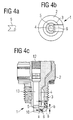
- Fig. 4a
- eine Seitenansicht einer Mittelelektrode gemäß einem vierten Ausführungsbeispiel der vorliegenden Erfindung;
- Fig. 4b
- eine Unteransicht einer Zündkerze gemäß dem vierten Ausführungsbeispiel in Fig. 4a;
- Fig. 4c
- eine Vorderansicht, teilweise im Schnitt, einer Zündkerze gemäß dem vierten Ausführungsbeispiel in den Fig. 4a und 4b;
- Fig. 5a
- eine Unteransicht einer Zündkerze gemäß einem fünften Ausführungsbeispiel der vorliegenden Erfindung;
- Fig. 5b
- eine Vorderansicht, teilweise im Schnitt, einer Zündkerze gemäß dem fünften Ausführungsbeispiel in Fig. 5a;
- Fig. 6
- eine Unteransicht einer Zündkerze gemäß einem sechsten Ausführungsbeispiel der vorliegenden Erfindung;
- Fig. 7
- eine Vorderansicht, teilweise im Schnitt, einer Zündkerze gemäß einem siebten Ausführungsbeispiel der vorliegenden Erfindung;
- Fig. 8a
- eine Unteransicht einer Zündkerze gemäß einem achten Ausführungsbeispiel der vorliegenden Erfindung;
- Fig. 8b
- eine Vorderansicht, teilweise im Schnitt, einer Zündkerze gemäß dem achten Ausführungsbeispiel in Fig. 8a;
- Fig. 9
- eine Vorderansicht, teilweise im Schnitt, einer Zündkerze gemäß einem neunten Ausführungsbeispiel der vorliegenden Erfindung;
- Fig. 10
- eine Vorderansicht, teilweise im Schnitt, einer Zündkerze gemäß einem zehnten Ausführungsbeispiel der vorliegenden Erfindung;
- Fig. 11
- eine Vorderansicht, teilweise im Schnitt, einer Zündkerze gemäß einem elften Ausführungsbeispiel der vorliegenden Erfindung;
- Fig. 12
- eine Vorderansicht, teilweise im Schnitt, einer Zündkerze gemäß einem zwölften Ausführungsbeispiel der vorliegenden Erfindung;
- Fig. 13
- eine Vorderansicht, teilweise im Schnitt, einer Zündkerze gemäß einem dreizehnten Ausführungsbeispiel der vorliegenden Erfindung;
- Fig. 14a
- eine Unteransicht einer Zündkerze gemäß einem vierzehnten Ausführungsbeispiel der vorliegenden Erfindung;
- Fig. 14b
- eine Vorderansicht, teilweise im Schnitt, einer Zündkerze gemäß dem vierzehnten Ausführungsbeispiel in Fig. 14a;
- Fig. 15a
- eine Unteransicht einer Zündkerze gemäß einem fünfzehnten Ausführungsbeispiel der vorliegenden Erfindung;
- Fig. 15b
- eine Vorderansicht, teilweise im Schnitt, einer Zündkerze gemäß dem fünfzehnten Ausführungsbeispiel in Fig. 15a;
- Fig. 16
- eine Vorderansicht eines Einspritzventils gemäß einem Ausführungsbeispiel der vorliegenden Erfindung; und
- Fig. 17
- eine Brennraumanordnung gemäß einem weiteren Ausführungsbeispiel der vorliegenden Erfindung.
- Fig. 1a
- a bottom view of a combustion chamber arrangement with a spark plug and an injection valve according to a first embodiment of the present invention;
- Fig. 1b
- a front view, partially in section, of a spark plug according to the first embodiment in Fig. 1a;
- Fig. 2
- a front view, partly in section, of a spark plug according to a second embodiment of the present invention;
- Fig. 3
- a front view, partly in section, of a spark plug according to a third embodiment of the present invention;
- Fig. 4a
- a side view of a center electrode according to a fourth embodiment of the present invention;
- Fig. 4b
- a bottom view of a spark plug according to the fourth embodiment in Fig. 4a;
- Fig. 4c
- a front view, partly in section, of a spark plug according to the fourth embodiment in FIGS. 4a and 4b;
- Fig. 5a
- a bottom view of a spark plug according to a fifth embodiment of the present invention;
- Fig. 5b
- a front view, partly in section, of a spark plug according to the fifth embodiment in Fig. 5a;
- Fig. 6
- a bottom view of a spark plug according to a sixth embodiment of the present invention;
- Fig. 7
- a front view, partly in section, of a spark plug according to a seventh embodiment of the present invention;
- Fig. 8a
- a bottom view of a spark plug according to an eighth embodiment of the present invention;
- Fig. 8b
- a front view, partially in section, of a spark plug according to the eighth embodiment in Fig. 8a;
- Fig. 9
- a front view, partly in section, of a spark plug according to a ninth embodiment of the present invention;
- Fig. 10
- a front view, partly in section, of a spark plug according to a tenth embodiment of the present invention;
- Fig. 11
- a front view, partly in section, of a spark plug according to an eleventh embodiment of the present invention;
- Fig. 12
- a front view, partly in section, of a spark plug according to a twelfth embodiment of the present invention;
- Fig. 13
- a front view, partly in section, of a spark plug according to a thirteenth embodiment of the present invention;
- 14a
- a bottom view of a spark plug according to a fourteenth embodiment of the present invention;
- 14b
- a front view, partially in section, of a spark plug according to the fourteenth embodiment in Fig. 14a;
- 15a
- a bottom view of a spark plug according to a fifteenth embodiment of the present invention;
- 15b
- a front view, partly in section, of a spark plug according to the fifteenth embodiment in Fig. 15a;
- Fig. 16
- a front view of an injection valve according to an embodiment of the present invention; and
- Fig. 17
- a combustion chamber arrangement according to a further embodiment of the present invention.
In den Figuren bezeichnen gleiche Bezugszeichen gleiche oder funktionsgleiche Komponenten.In the figures, the same reference symbols designate the same or functionally identical components.
Die Fig. 1a und 1b zeigen eine Unter- bzw. Vorderansicht, teilweise im Schnitt, einer Zündkerze 1 gemäß einem ersten Ausführungsbeispiel der vorliegenden Erfindung.1a and 1b show a bottom and front view, partly in section, a spark plug 1 according to a first Embodiment of the present invention.
In einem beispielsweise metallischen, rohrförmigen Gehäuse
2 der Zündkerze 1 ist ein Isolator 4 angeordnet, wobei vorteilhaft
die rotationssymmetrischen Achsen des Gehäuses 2
und des Isolators 4 deckungsgleich liegen. In dem Isolator
4 ist eine vorzugsweise stabförmige Innenleiteranordnung
mit einem Anschlussbolzen 11 (siehe Fig. 12 und 13), einem
strombegrenzenden Widerstand 12 und einem beschichteten
Kontaktstift 13 sowie eine Mittelelektrode 5 angeordnet,
welche beispielsweise aus einer Sonderlegierung, Platin oder
dergleichen, angefertigt ist. Die in dem Isolator 4 angeordneten
Bauteile dienen einer Übertragung der Spannung
vom Anschlussbolzen 11 an die Mittelelektrode 5. Zwischen
dem Gehäuse 2 und dem Isolator 4, der beispielsweise aus
einer Keramik besteht, ist ein Atmungsvolumen 3 vorgesehen.
Der Anschlussbolzen 11 besteht vorzugsweise aus Stahl. Innerhalb
des Isolators 4 werden der Anschlussbolzen 11 und
die Mittelelektrode 5 in einer leitenden Spezialschmelze,
vorzugsweise absolut dicht, verankert. Der Isolator wird
zusammen mit einem Dichtring und beispielsweise einem Bördelring
in das Stahl-Kerzengehäuse 2 eingesetzt und durch
ein Spezialverfahren unter hohem Druck eingebördelt und geschrumpft.In a metallic, tubular housing, for example
2 of the spark plug 1, an
Die Zündkerze 1 weist ferner eine Masseelektrode 6 auf, die
an dem Gehäuse 2 der Zündkerze 1 beispielsweise angeschweißt
ist. Die Masseelektrode 6 besteht zum Beispiel ebenfalls
aus einer Speziallegierung.The spark plug 1 also has a
Wie in den Fig. 1 und 1b ersichtlich, ist die Masseelektrode
6 gemäß dem ersten Ausführungsbeispiel der vorliegenden
Erfindung haken- bzw. dachförmig ausgebildet, wobei die
Masseelektrode 6 die Mittelelektrode 5 abdeckt. Die Masseelektrode
6 besitzt einen parallel zur Achse der Zündkerze
1 verlaufenden Abschnitt 6a, der am Gehäuse 2 angeschweißt
ist, und einen quer zu dieser Achse verlaufenden Dachabschnitt
6b. Die Masseelektrode 6 weist vorzugsweise in Höhe
der Funkenstrecke zwischen der brennraumseitigen Fläche der
Mittelelektrode 5 und der entsprechend gegenüberliegenden
Fläche der Masseelektrode 6 mindestens eine Bohrung 8, einen
Schlitz, eine Aussparung oder dergleichen auf. Dadurch
wird vermieden, dass bei einer Einbauposition, bei welcher
sich die Masseelektrode 6 zwischen einem Einspritzventil 20
und der Mittelelektrode 5 befindet, sich die Funkenstrecke
im Windschatten der Masseelektrode 6 befindet und daher von
der Gemischströmung 25 nicht erfasst werden kann.As can be seen in FIGS. 1 and 1b, the
Neben der Zündkerze 1 ist in dem Brennraum ein Einspritzventil
20 vorgesehen, welches vorzugsweise einen halbkugelförmigen
Kopf 21 mit mehreren Einspritzlöchern 22, 22'; 23,
23' (siehe Fig. 16 und 17) aufweist. Das aus dem Einspritzventil
20 ausströmende Gemisch ist in den Figuren durch den
Schwerpunktstrahl des jeweiligen Einspritzstrahls 25 repräsentativ
dargestellt.In addition to the spark plug 1, there is an injection valve in the
Somit wird unabhängig von der Einbauposition der Zündkerze
1 eine ausreichende Gemischströmung zur Funkenstrecke a
zwischen der Mittelelektrode 5 und der Masseelektrode 6 und
somit eine zuverlässige Gemischentflammung gewährleistet.This makes it independent of the installation position of the spark plug
1 a sufficient mixture flow to the spark gap a
between the
Die Masseelektrode 6 kann auch aus zwei parallel voneinander
beabstandeten Elektroden ausgebildet sein, um den Gemischzutritt
zur Funkenstrecke a sicherzustellen.The
In dem ersten Ausführungsbeispiel ist der Abstand a der
Mittelelektrode 5 zur Masseelektrode 6 in axialer Richtung
wesentlich geringer als der Abstand b zwischen dem Isolator
4 und dem parallel zur Achse der Zündkerze 1 verlaufenden
Abschnitt 6a der Masseelektrode 6. Somit erfolgt eine Zündung
bzw. eine Entflammung des Gemisches lediglich an der
Funkenstrecke a, falls die Strecke b größer als der notwendige
Zündabstand gewählt ist. In the first embodiment, the distance a is the
Wie in Fig. 1b dargestellt, ist die Mittelelektrode 5 im
Vergleich zum Isolator 4 verlängert und ragt brennraumseitig
hervor. Zum Erzielen einer möglichst großen Einbautoleranz
ist die Funkenstrecke a möglichst weit außerhalb des
Kerzengehäuses 2 zu legen, soweit es aus thermischen und
fertigungstechnischen Gründen vertretbar ist. Dadurch können
unterschiedliche Einbautoleranzen der Funkenstrecke,
bezogen auf die jeweiligen benachbarten Einspritzstrahlen,
bei Motoren mit mehreren Zylindern ausgeglichen werden und
es besteht eine Toleranz-Unempfindlichkeit der Funkenstrecke
hinsichtlich unterschiedlicher Einbautiefen der Zünderkerze
1 in den einzelnen Zylindern.As shown in Fig. 1b, the
Wie der Fig. 1b zu entnehmen ist, kann die Mittelelektrode
5 frei liegen, d.h. ohne von dem Isolator 4 umgeben zu
sein.As can be seen from FIG. 1b, the
Fig. 2 zeigt eine Vorderansicht in teilweise geschnittener
Darstellung einer Zündkerze 1 gemäß einem zweiten Ausführungsbeispiel
der vorliegenden Erfindung. Die Mittelelektrode
5 besitzt in diesem Ausführungsbeispiel vorzugsweise
die Form eines Stiftes, der axial auf dem brennraumseitigen
Ende des Kontaktstiftes 13 angebracht ist. Vorzugsweise ist
die Mittelelektrode 5 aus Platin gebildet und mittels einem
Schweißverfahren an dem Kontaktstift 13 angebracht. Die
Mittelelektrode 5 kann für eine ausreichende Gemischzugänglichkeit
zur Funkenstrecke zwischen der Mittelelektrode 5
und der Masseelektrode 6 von zwei parallel geführten Masseelektroden
oder von einer gegabelten Masseelektrode 6, wie
in Fig. 2 ersichtlich, flankiert werden. In diesem Fall erfolgt
eine Zündung sowohl in axialer Richtung über die Funkenstrecke
a zwischen dem Kontaktstift 13 und der Masseelektrode
6 als auch in radialer Richtung über die Funkenstrecke
b zwischen der Mittelelektrode 5 und der Masseelektrode
6.Fig. 2 shows a front view in partially sectioned
Representation of a spark plug 1 according to a second embodiment
of the present invention. The
Der jeweils freie Bereich der zwei parallel geführten Masseelektroden
bzw. der gegabelten Masseelektrode dient einem
Zuführbereich zum Zuführen des brennbaren Gemisches an die
jeweilige Funkenstrecke. Zusätzlich kann die Masseelektrode
6 wiederum Bohrungen, Schlitze, Aussparungen oder dergleichen
für eine Gemischzuführhilfe aufweisen.The free area of the two ground electrodes in parallel
or the forked ground electrode serves one
Feed area for feeding the combustible mixture to the
respective spark gap. In addition, the
In diesem Ausführungsbeispiel nicht beschriebene Bauteile und Funktionsweisen entsprechen denen des ersten Ausführungsbeispiels in den Fig. 1a und 1b und bedürfen daher keiner weiteren Erläuterung. Analoges gilt im Übrigen auch für die folgenden Ausführungsbeispiele.Components not described in this embodiment and functions correspond to those of the first exemplary embodiment in Figs. 1a and 1b and therefore need no further explanation. The same also applies for the following embodiments.
In Fig. 3 ist ein drittes Ausführungsbeispiel einer Zündkerze
1 dargestellt, bei der die Masseelektrode 6 derart
gestuft ausgebildet ist, dass sie die Mittelelektrode 5 sowie
die Isolatorstirnfläche unter Bildung eines bestimmten
Abstandes überdeckt. Bei einer solchen Ausbildung kommt es
in axialer Richtung über der in Fig. 3 gekennzeichneten
Funkenstrecke a, in radialer Richtung über der Funkenstrecke
b und zusätzlich über der Funkenstrecke c zwischen dem
Isolator 4 und dem Überhangabschnitt 6c der Masseelektrode
6 zu einem Zündvorgang.In Fig. 3 is a third embodiment of a spark plug
1, in which the
Vorzugsweise besitzt die Masseelektrode 6 in Höhe der jeweiligen
Funkenstrecke eine Bohrung 8, einen Schlitz, eine
Aussparung oder dergleichen, so dass unabhängig von der
Einbauposition eine ausreichende Gemischströmung zur entsprechenden
Funkenstrecke gewährleistet ist.The
Ferner weist gemäß dem dritten Ausführungsbeispiel die Mittelelektrode
5 in Höhe der Funkenstrecke b bzw. c ebenfalls
eine Bohrung 10, einen Schlitz, eine Aussparung oder dergleichen
für eine ausreichende Zugänglichkeit des Gemisches
zur Funkenstrecke b bzw. c auf.Furthermore, according to the third exemplary embodiment, the
Der Abstand d zwischen den parallel zueinander beabstandeten
Abschnitten des Isolators 4 und der Masseelektrode 6
ist vorzugsweise um einiges größer gewählt als die Abstände
bzw. Funkenstrecken a, b und c. Somit kommt es an der Strecke
d zu keiner Entflammung bzw. zu keinem Zündvorgang.The distance d between the parallel spaced
Portions of the
Die Fig. 4a, 4b und 4c illustrieren eine Zündkerze gemäß
einem vierten Ausführungsbeispiel der vorliegenden Erfindung.
In Fig. 4a ist eine rechtsseitige Ansicht einer Mittelelektrode
5 dargestellt, die eine in etwa V-förmige Aussparung
aufweist. Die Fig. 4b und 4c illustrieren eine Unter-
bzw. Vorderansicht, teilweise im Schnitt, einer Zündkerze
1 gemäß dem vierten Ausführungsbeispiel. Die Masseelektrode
6 ist gebogen ausgestaltet, derart, dass sie
brennraumseitig mit der Mittelelektrode 5 abschließt. Die
Masseelektrode 6 besitzt erfindungsgemäß in Höhe der relevanten
Funkenstrecken a und b eine Bohrung 8, einen
Schlitz, eine Aussparung oder dergleichen. In diesem Ausführungsbeispiel
ist der Abstand c größer gewählt als die
Abstände a und b, so dass eine Vollfunkenbildung lediglich
an den Funkenstrecken a und b zustande kommt.4a, 4b and 4c illustrate a spark plug according to
a fourth embodiment of the present invention.
4a is a right side view of a
Für eine bessere Entflammung können auch mehrere Masseelektroden,
beispielsweise in gleichmäßigen Winkelabständen,
um die Mittelelektrode 5 angeordnet werden, die allesamt
für eine verbesserte Gemischzugänglichkeit entsprechende
Bohrungen 8, Schlitze, Aussparungen oder dergleichen
aufweisen. Ein Vorteil einer derartigen Konstruktionssymmetrie
besteht in der großen Toleranz in der Einbaurichtung
der Zündkerze 1.For better ignition, several ground electrodes,
for example at regular angular intervals,
can be arranged around the
Die Zündung erfolgt hierbei in radialer Richtung zur Mittelelektrode
5 über die Funkenstrecke a und in axialer
Richtung zum Isolator 4 über die Funkenstrecke b. Der Isolator
4 ist vorzugsweise aus Keramik oder dergleichen gebildet.The ignition takes place in the radial direction to the
Ein fünftes Ausführungsbeispiel der vorliegenden Erfindung
ist in den Fig. 5a und 5b dargestellt. Gemäß diesem Ausführungsbeispiel
ist die Masseelektrode 6 gabelförmig ausgebildet
und umschließt die Mittelelektrode 5 zumindest teilweise.
Dadurch wird der Bereich der Funkenstrecke erweitert.
Der die gabelförmige Masseelektrode 6 nicht umschließende
Bereich der Gabelelektrode dient einer Zuführung des
brennbaren Gemisches zur entsprechenden Funkenstrecke. Die
gabelförmige Masseelektrode 6 ist wiederum mit einer Bohrung
8, einem Schlitz, einer Aussparung oder dergleichen
vorzugsweise in Höhe der Funkenlage ausgebildet.A fifth embodiment of the present invention
is shown in Figs. 5a and 5b. According to this embodiment
the
Der Querschnitt der Gabelzinken kann rechteckförmig, quadratisch, rund, dreieckig oder dergleichen sein. Dies gilt analog für die Elektrodenquerschnitte der übrigen Ausführungsbeispiele.The cross section of the forks can be rectangular, square, be round, triangular or the like. this applies analogously for the electrode cross sections of the other exemplary embodiments.
Die von der gabelförmigen Masseelektrode 6 umgebene Mittelelektrode
5 ist gegenüber dem Isolator 4 brennraumseitig
verlängert. Eine Entzündung erfolgt hierbei in radialer
Richtung über die Funkenstrecke a zwischen der Masseelektrode
6 und der Mittelelektrode 5 und in axialer Richtung
über die Funkenstrecke b zwischen der Masseelektrode 6 und
dem Isolator 4.The center electrode surrounded by the fork-shaped
Fig. 6 zeigt eine Unteransicht einer Zündkerze 1 gemäß einem
sechsten Ausführungsbeispiel der vorliegenden Erfindung.
Die Masseelektrode besteht aus zwei parallel zueinander
geführten Elektroden, die an der Mittelelektrode 5 vorbeigeführt
und sowohl zur Mittelelektrode 5 als auch zur
Stirnfläche des Isolators 4 zünden. Die beiden Elektroden
sind vorzugsweise punktsymmetrisch bezüglich der Achse der
Mittelelektrode 5 an das Gehäuse 2 der Zündkerze 1 oder an
eine weitere Masseelektrode angeschweißt. Der Zwischenbereich
8 zwischen den beiden Elektroden dient einer verbesserten
Zugänglichkeit des brennbaren Gemisches zur Funkenstrecke.6 shows a bottom view of a spark plug 1 according to a
sixth embodiment of the present invention.
The ground electrode consists of two parallel to each other
guided electrodes, which passes the
Die beiden Masseelektroden können auch auf derselben Seite
der Mittelelektrode 5 am Gehäuse 2 der Zündkerze 1, d.h.
achsensymmetrisch, befestigt sein. Ebenso können die Masseelektroden
jeweils als Bügel auf beiden Seiten der Mittelelektrode
5 am Gehäuse 2 der Zündkerze 1 befestigt werden.
Durch eine bogenförmige Ausbuchtung im Bereich der Mittelelektrode
5 können die Masseelektroden vorzugsweise zusätzlich
an den Kreisquerschnitt der Mittelelektrode 5 angepasst
werden.The two ground electrodes can also be on the same side
the
Hierbei erfolgt eine Zündung in radialer Richtung zur Mittelelektrode
5 und in axialer Richtung zum Isolator 4.Ignition takes place in the radial direction to the
Der Querschnitt der Elektroden kann, wie vorher bereits erwähnt, quadratisch, rund, viereckig, dreieckig oder dergleichen sein.The cross-section of the electrodes can, as previously mentioned, square, round, square, triangular or the like his.
Gemäß dem Ausführungsbeispiel in Fig. 7 ist die Masseelektrode
6 als quer über den Durchmesser des Kerzengehäuses 2
gespannter Bügel ausgebildet. Die Mittelelektrode 5
schließt dabei bündig mit der Stirnfläche des Isolators 4
ab. Die Masseelektrode 6 besitzt vorzugsweise an beiden
Eckbereichen des Bügels jeweils eine Bohrung 8. Anstatt der
beiden Bohrungen 8 kann der Bügel auch teilweise an seinen
Rundungen oder im gesamten Bereich des Bügels durchgeschlitzt
werden. 7 is the
Anstelle eines einzelnen breiteren Bügels können auch zwei
parallel zueinander beabstandete schmalere Bügel verwendet
werden, die beispielsweise einseitig an dem Gehäuse 2 der
Zündkerze 1 angeschweißt sind.Instead of a single wider bracket, two can be used
used narrower brackets spaced parallel to each other
be, for example, one-sided on the
Eine Zündung erfolgt in diesem Ausführungsbeispiel über die
Funkenstrecke a zwischen der Stirnfläche der Mittelelektrode
5 und der gegenüberliegenden Fläche der Masseelektrode
6.In this exemplary embodiment, ignition takes place via the
Spark gap a between the end face of the
Gemäß einem achten Ausführungsbeispiel der vorliegenden Erfindung,
wie in Fig. 8a und 8b dargestellt, ist die Masseelektrode
6 ringförmig ausgebildet und umschließt die Mittelelektrode
5, welche vorzugsweise über die Stirnfläche
des Isolators 4 verlängert ist und aus dem Isolator 4
brennraumseitig herausragt.According to an eighth embodiment of the present invention,
as shown in Figures 8a and 8b, is the
Die ringförmige Masseelektrode 6 ist vorzugsweise mittels
gegenüberliegend angeordneten Ringträgern 7 an dem Gehäuse
2 der Zündkerze 1 angeschweißt. Die Masseelektrode 6 besitzt
vorteilhaft in Höhe der Funkenstrecke a bzw. b Bohrungen
8, Schlitze oder dergleichen, die vorzugsweise in
den Ringträgern 7 für einen besseren Gemischzugang zur Funkenstrecke
vorgesehen sind. Die Ringträger der ringförmigen
Masseelektrode 6 sind vorzugsweise im eingebauten Zustand
parallel zur Strömungsrichtung des brennbaren Gemisches gerichtet,
damit eine Zuführung des Gemisches zur Funkenstrecke
durch den Träger nicht gestört werden und nicht die Gefahr
von eventuell auftretenden Thermoschocks besteht.The ring-shaped
Hierbei erfolgt die Zündung in radialer Richtung über die
Funkenstrecke a zur Mittelelektrode 5 und in axialer Richtung
über die Funkenstrecke b zum Keramikisolator 4.The ignition takes place in the radial direction via the
Spark gap a to the
Das Querschnittsprofil der ringförmigen Masseelektrode 6
ist vorzugsweise rund ausgebildet.The cross-sectional profile of the ring-shaped
Fig. 9 zeigt eine Vorderansicht, teilweise im Schnitt, einer
Zündkerze 1 gemäß einem neunten Ausführungsbeispiel der
vorliegenden Erfindung. Die Mittelelektrode 5 weist einen
Kopf auf, dessen Durchmesser dem Außendurchmesser des Isolators
4 an der Berührungsfläche entspricht. Das Gehäuse 2
der Zündkerze 1 übernimmt gemäß diesem Ausführungsbeispiel
die Funktion der Masseelektrode 6, wobei aufgrund der zurückgezogenen
Masseelektrode 6 der Zündfunke vom Nagelkopf
der Mittelelektrode 5 über den Isolator 4 zur Masseelektrode
6 bzw. Gehäuse 2 wandert. Ohne einen nagelförmigen Kopf
würde der Funke direkt von der Mittelelektrode 5 zur Masseelektrode
6 übergehen und Furcheneingrabungen im Isolator 4
zur Folge haben. Dies wiederum könnte ein Aussetzen des Motors
aufgrund einer zu geringen Brenngemischmenge bedeuten.Fig. 9 shows a front view, partly in section, one
Spark plug 1 according to a ninth embodiment of the
present invention. The
Der Sitz für den Isolator 4 kann in Richtung des Anschlussbolzens
11 verschoben werden, um einen zusätzlichen Atmungsraum
3 für heißere Zündkerzenvarianten zu gewinnen. The seat for the
Aufgrund der verlängerten Funkenstrecke wird eine variable Einbautiefe, eine hohe Nebenschlussempfindlichkeit und eine vorteilhafte Rotationssymmetrie erreicht.Due to the extended spark gap, a variable Installation depth, a high shunt sensitivity and a advantageous rotational symmetry achieved.
In Fig. 10 ist eine Zündkerze 1 gemäß einem zehnten Ausführungsbeispiel
der vorliegenden Erfindung dargestellt, wobei
die Mittelelektrode 5 analog zum neunten Ausführungsbeispiel
nagelkopfförmig ausgebildet ist.10 is a spark plug 1 according to a tenth embodiment
of the present invention, wherein
the
Zwischen dem Gehäuse 2 der Zündkerze 1 und dem Nagelkopf
der Mittelelektrode 5 ist eine vorzugsweise ringförmige
Masseelektrode 6 vorgesehen, die mittels Ringträgern 7 am
Gehäuse 2 der Zündkerze 1 befestigt ist. Der Abstand zwischen
der ringförmigen Masseelektrode 6 und dem Keramikisolator
4 sollte möglichst klein gehalten werden, jedoch derart
toleriert sein, dass die unterschiedlichen Wärmeausdehnungen
des Isolators 4 und der ringförmigen Masseelektrode
6 berücksichtigt sind.Between the
Die Ringträger 7 der ringförmigen Masseelektrode 6 können
für eine bessere Zugänglichkeit des Gemisches zur Funkenstrecke
Bohrungen, Schlitze, Aussparungen oder dergleichen
aufweisen. Ferner kann die Masseelektrode 6 auch als
Halbring mit einem oder zwei Ringträgern ausgebildet sein,
wobei sich der Halbring vorzugsweise auf der strömungszugewandten
Seite befindet. The
Somit wird vorteilhaft eine Rotationssymmetrie, eine Nebenschluss-Unempfindlichkeit und eine variable Einbautiefe geschaffen.A rotational symmetry, a shunt insensitivity, is thus advantageous and created a variable installation depth.
In Fig. 11 ist eine Vorderansicht, teilweise im Schnitt,
einer Zündkerze 1 gemäß einem elften Ausführungsbeispiel
der vorliegenden Erfindung dargestellt. Die Mittelelektrode
5 ist dabei gekröpft ausgebildet und derart radial nach außen
gebogen, dass die Funkenstrecke außerhalb der Achse der
Zündkerze 1 verlegt ist. Die Masseelektrode 6 ist am Gehäuse
2 der Zündkerze 1 vorzugsweise angeschweißt und parallel
zur Achse der Zündkerze 1 ausgerichtet.11 is a front view, partly in section,
a spark plug 1 according to an eleventh embodiment
of the present invention. The
Die Masseelektrode 6 kann auch als doppelte, parallel geführte
Masseelektrode ausgebildet sein, die vorzugsweise in
Höhe der Funkenlage eine Bohrung, einen Schlitz, eine Aussparung
oder dergleichen aufweist.The
Wie in Fig. 11 dargestellt, weist die Mittelelektrode 5
vorzugsweise in Höhe der Funkenstrecke eine Bohrung 10 für
eine bessere Zugänglichkeit des Gemisches zur Funkenstrecke
auf. Eine derartige Zuführhilfe kann auch mittels Schlitzen,
Aussparungen oder dergleichen ausgebildet sein.As shown in FIG. 11, the
Gemäß einem zwölften Ausführungsbeispiel der vorliegenden
Erfindung ist die Masseelektrode 6 analog zum ersten Ausführungsbeispiel
dachförmig ausgebildet und weist vorzugsweise
in Höhe der Funkenstrecke eine Bohrung 8, einen
Schlitz, eine Aussparung oder dergleichen für eine bessere
Zugänglichkeit des brennbaren Gemisches zur Funkenstrecke
auf.According to a twelfth embodiment of the present
Invention is the
Die Mittelelektrode 5 ist gemäß dem vorliegenden Ausführungsbeispiel
in die Isolationskeramik 4 eingebettet, wodurch
eine Luftfunkenzündung über den Isolator 4 stattfindet,
welche die Verbrennungsablagerungen beim Zündvorgang
beseitigt. Somit werden die Isolationseigenschaften des Isolators
4 aufrecht erhalten. Die Mittelelektrode 5 kann
mit einem dünnen Platinstift, der in den Isolator 4 eingebettet
ist, verschweißt werden.The
Anstatt einer dachförmig gebogenen Masseelektrode 6 können
beispielsweise auch zwei parallel geführte Masseelektroden
vorgesehen sein.Instead of a roof-shaped
Wie vorher bereits erwähnt, treffen die Strahlen des brennbaren Gemisches vorzugsweise oberhalb der Funkenstrecke auf die Zündkerzenanordnung, wodurch eine Teilablenkung des Einspritzstrahls für eine zufriedenstellende Zulieferung des Gemisches an die Funkenstrecke sorgt.As mentioned earlier, the rays of the flammable hit Mixtures preferably above the spark gap the spark plug assembly, thereby partially deflecting the Injection jet for a satisfactory delivery of the mixture to the spark gap.
Die Mittelelektrode 5 kann gemäß einem weiteren Ausführungsbeispiel,
wie in Figur 13 dargestellt, nagelkopfförmig
ausgebildet sein und mit einer dachförmigen Masseelektrode
6 eine ausreichend zugängliche Funkenstrecke bilden. Die
Masseelektrode 6 ist beispielsweise analog zum zwölften
Ausführungsbeispiel ausgestaltet. Die nagelkopfförmige Mittelelektrode
5 überdeckt dabei den Isolator 4. According to a further exemplary embodiment, the
Durch die oben beschriebene Ausführung werden die Gemischstrahlen
analog zum vorherigen Ausführungsbeispiel teilabgelenkt
und zur Funkenstrecke für einen Zündvorgang geführt.
Figur 14a und 14b illustrieren eine Unteransicht
bzw. eine Vorderansicht, teilweise im Schnitt, einer Brennraumanordnung,
gemäß einem vierzehnten Ausführungsbeispiel
der vorliegenden Erfindung. Die Mittelelektrode 5 ist gegenüber
dem Isolator 4 verlängert ausgebildet und ragt
brennraumseitig über die Stirnfläche des Isolators 4 stiftförmig
hinaus. Dies kann entweder durch eine Verkürzung der
Isolationskeramik 4 oder einer Verlängerung der Mittelelektrode
5 erfolgen.Due to the design described above, the mixture jets
analogous to the previous embodiment partially deflected
and led to the spark gap for an ignition process.
Figures 14a and 14b illustrate a bottom view
or a front view, partly in section, of a combustion chamber arrangement,
according to a fourteenth embodiment
of the present invention. The
Die Masseelektrode 6 besteht beispielsweise aus zwei in einem
spitzen Winkel zueinander angeordneten Elektroden, welche
parallel zur Achse der Zündkerze an dem Gehäuse 2 angeschweißt
sind und brennraumseitig bezüglich der Mittelelektrode
5 verlängert sind. Zudem weisen die beiden Elektroden
vorzugsweise einen Umlenkbereich 9 auf, der am unteren
Ende als Reflektionsfläche derart angeordnet ist, dass
die auf die Elektroden auftreffenden Gemischstrahlen in
Richtung Funkenstrecke umgelenkt werden. Dabei wird das
brennbare Gemisch vorzugsweise auf der strömungsabgewandten
Seite der Mittelelektrode 5 gezündet, an der eine höhere
Gemischkonzentration vorhanden ist.The
Die Funkenstrecke liegt hierbei vorzugsweise etwas unterhalb der einfallenden Gemischstrahlen, da eine direkte Einspritzung die Gefahr eines Verblasens des Funkens beinhaltet. Durch die Teilablenkung bzw. Umlenkung kann somit eine stabile Entflammung erreicht werden, ohne dass der Funkenkern durch die einfallenden Gemischstrahlen "Verblasen" wird.The spark gap is preferably somewhat below of the incoming mixture jets, as a direct injection involves the danger of the spark blowing away. Due to the partial deflection or deflection, a stable ignition can be achieved without the spark core "Blowing" through the incoming mixture jets becomes.
Es sind verschiedene Ausgestaltungen der Masseelektrode 6
denkbar, entscheidend ist lediglich, dass diese einen Umlenkbereich
für eine Umlenkung der Gemischstrahlen zur Funkenstrecke
aufweisen.There are various configurations of the
Beispielsweise, wie in Figur 15a bzw. 15b dargestellt,
weist die Masseelektrode 6 bezüglich des vorherigen Ausführungsbeispiels
einen zusätzlichen, zur Stirnfläche der Mittelelektrode
5 parallel verlaufenden Umlenkbereich 9 auf,
d.h. die Masseelektrode 6 ist dachförmig verlängert und um
die nagelkopfförmig ausgebildete Mittelelektrode 5 herumgeführt.
Somit werden die Einspritzstrahlen wiederum teilabgelenkt
und der Funkenstrecke indirekt zugeführt.For example, as shown in FIGS. 15a and 15b,
has the
Eine weitere Möglichkeit, die Einbautiefentoleranz einer
Zündkerze 1 zu erweitern, besteht in einer Modifikation des
Einspritzventils 20 bzw. in der Modifikation der Brennraumanordnung
von Einspritzventil 20 und Zündkerze 1.Another option is the installation depth tolerance
Extending spark plug 1 is a modification of
Das Einspritzventil 20 besitzt vorzugsweise einen halbkugelförmigen
Kopf 21, wie aus Figur 16 ersichtlich, in dem
eine spezielle Anordnung an Einspritzlöchern vorgesehen
ist. Der Einspritzlochquerschnitt sollte möglichst klein
gewählt sein, um eine Überfettung an der Zündkerze zu vermeiden.
Vorzugsweise sind das Einspritzventil 20 und die
Zündkerze 1 derart zueinander angeordnet, dass deren Achsen
einen spitzen Winkel miteinander bilden, wie in Figur 17
dargestellt.The
Der kugelförmige Kopf 21 des Einspritzventils 20 besitzt
vorzugsweise mehrere Paare von Einspritzlöchern 22, 22';
23, 23', die vorzugsweise derart angeordnet werden, dass
jeweils die eingespritzten Gemischstrahlen 25 eines Paares
an Einspritzlöchern 22, 22' die Zündkerze jeweils seitlich
flankieren und der Schwerpunkt der Gemischstrahlenkeule
vorzugsweise oberhalb der Funkenstrecke zwischen der Mittelelektrode
5 und der Masseelektrode 6 der Zündkerze 1
liegt.The
Vorzugsweise sind für verschiedene Einbaupositionen bzw. Einbautiefen der Zündkerze 1 verschiedene Lochpaare zugeordnet, so dass in verschiedenen Einbaupositionen das entsprechend zugeordnete Lochpaar für eine günstige Gemischstrahlenzuführung sorgt.For different installation positions or Installation depths of the spark plug assigned to 1 different pairs of holes, so that in different installation positions assigned pair of holes for a favorable mixture jet feed provides.
Der Winkel β zwischen den aus den beiden Einspritzlöchern
22 und 22' bzw. 23 und 23' austretenden Gemischstrahlen
liegt jeweils vorzugsweise zwischen 30° und 60°, d.h. die
beiden die Zündkerze 1 flankierenden Strahlen weisen vorzugsweise
einen solchen Winkel auf. The angle β between those from the two
Der Winkel α zwischen den beiden Ebenen, die jeweils durch
die aus den Löchern 22, 22' und 23, 23' austretenden Strahlen
dreieckförmig aufgespannt werden, liegt vorzugsweise
zwischen 20° und 35°.The angle α between the two levels, each through
the rays emerging from
Die Wirksamkeit der Toleranzerweiterung für die Einbautiefe
der Zündkerze 1 besteht darin, dass die Strahlen der Einspritzlöcher
22 und 22' jeweils rechts und links der Zündkerze
1 eine Ebene aufspannen, die eine zuverlässige Zündung
und Entflammung der entstehenden Gemischwolke im Bereich
der Funkenstrecke in relativer Unabhängigkeit von der
Einbautiefe der Zündkerze 1 sicherstellt. Durch die zweite
Strahlebene, bestehend aus dem den Löchern 23 und 23' zugewiesenen
Strahlenpaar kann die Einbautiefentoleranz der
Zündkerze zusätzlich erweitert werden.The effectiveness of the tolerance extension for the installation depth
the spark plug 1 is that the rays of the injection holes
22 and 22 'on the right and left of the spark plug
1 spanning a level that provides reliable ignition
and ignition of the resulting mixture cloud in the area
the spark gap in relative independence from the
Installation depth of the spark plug 1 ensures. By the second
Beam level consisting of that assigned to
Für eine optimierte Zünd- und Entflammungsbedingung weist
die Zündkerze 1 vorteilhaft eine möglichst weit nach vorne
vorgezogene Funkenlage auf. Zudem sollte der Schwerpunkt
der Einspritzstrahlkeulen bzw. der von ihnen erzeugten Gemischwolke
oberhalb der Funkenstrecke liegen, d.h. in Richtung
des Kerzengehäuses 2. Bei einer derartigen Anordnung
werden zumindest ein Teil der Gemischstrahlen aufgrund ihrer
eigenen Geschwindigkeit von den entsprechenden Zündkerzenelektroden
zur Funkenstrecke hin abgelenkt, gezündet und
entflammt. Eine derartige Ablenkung kann sowohl an entsprechend
gestalteten Masseelektroden 6 als auch Mittelelektroden
5 erfolgen. Vorzugsweise sind die Ablenkbereiche 9 der
Elektroden gerade und im Bereich der Funkenstrecke ausgeführt.
Erfolgt eine Ablenkung an der Masseelektrode 6,
sollte die Funkenstrecke bezüglich der Längsachse der Zündkerze
1 in Richtung des Einspritzventils 20 liegen. Dies
kann beispielsweise mittels einer gebogenen Mittelelektrode
erreicht werden.
Somit schafft die vorliegende Erfindung eine Brennraumanordnung,
mit der eine Teilablenkung der Gemischwolke hin
zur Funkenstrecke ermöglicht und das brennbare Gemisch relativ
unabhängig von der Einbautiefe der Zündkerze bei fester
Einbauposition des Einspritzventils zuverlässig und sicher
entflammt werden kann. Je größer der Abstand zwischen
der Lage der Funkenstrecke und der Unterkante des Kerzengehäuses
2 ist, desto größer ist die Einbautoleranz bezüglich
der Einbautiefe der Zündkerze 1. Somit können unterschiedliche
Einbautoleranzen der Funkenlage, bezogen auf die jeweiligen
benachbarten Einspritzstrahlen bei Motoren mit
mehreren Zylindern ausgeglichen werden, wodurch eine Toleranzunempfindlichkeit
der Funkenlage hinsichtlich unterschiedlicher
Einbautiefen der Zündkerzen in den einzelnen
Zylindern, den Einbautiefen der Einspritzventile in den
einzelnen Zylindern und eventueller unterschiedlicher
Strahlwinkeltoleranzen der Einspritzventile besteht.For an optimized ignition and ignition condition, the spark plug 1 advantageously has a spark position that is drawn as far forward as possible. In addition, the center of gravity of the injection jet lobes or the mixture cloud generated by them should lie above the spark gap, ie in the direction of the
The present invention thus provides a combustion chamber arrangement with which a partial deflection of the mixture cloud towards the spark gap is made possible and the combustible mixture can be ignited reliably and safely relatively independently of the installation depth of the spark plug when the injection valve is in a fixed installation position. The greater the distance between the position of the spark gap and the lower edge of the
Für den Toleranzausgleich kann die Mittelelektrode frei liegen, d.h. ohne von einer Isolation umgeben zu sein. Jedoch besteht in diesem Fall die Gefahr von Glühzündungen im homogenen Betrieb. Somit werden die Mittelelektroden vorzugsweise mittels eines Isolationskörpers geschützt. The center electrode can be free for tolerance compensation lie, i.e. without being surrounded by isolation. however in this case there is a risk of glow ignition in the homogeneous operation. Thus, the center electrodes are preferred protected by an insulation body.
Obwohl die vorliegende Erfindung anhand bevorzugter Ausführungsbeispiele vorstehend beschrieben wurde, ist sie darauf nicht beschränkt, sondern auf vielfältige Weise modifizierbar.Although the present invention is based on preferred exemplary embodiments as described above, she is on it not limited, but can be modified in a variety of ways.
Insbesondere können, wie vorher bereits erwähnt, sämtliche Querschnittsprofile der Elektroden runde, quadratische, rechteckige, dreieckige oder ähnliche Formen entsprechend dem jeweiligen Anwendungszweck annehmen.In particular, as previously mentioned, all Cross-sectional profiles of the electrodes round, square, corresponding to rectangular, triangular or similar shapes accept the respective application.
An sämtlichen Stellen, an denen ein Gemischzugang durch die jeweiligen Elektroden bzw. die entsprechenden Träger behindert wird, können Durchbrüche, Bohrungen, Schlitze, Aussparungen oder dergleichen in den Elektroden bzw. deren Träger gebildet werden.At all points where a mixture access through the respective electrodes or the corresponding carrier hindered breakthroughs, holes, slots, recesses or the like is formed in the electrodes or their supports become.
Die vorgeschlagenen Elektrodenformen können auch unmittelbar bei Motoren mit Saugrohreinspritzung oder bei Motoren mit Direkteinspritzung nach dem wandgeführten und/oder luftgeführten Brennverfahren eingesetzt werden.The proposed electrode shapes can also be used directly for engines with intake manifold injection or for engines with direct injection after the wall-guided and / or air-guided combustion processes are used.
Generell kann die Zündkerze und die Zündanlage durch eine Glühstiftkerze mit Glühstromsteuerung ersetzt werden. Der Strombedarf der Glühstiftkerze wird in Abhängigkeit der Einspritzdauer des Kraftstoffs und der Kühlwassertemperatur gesteuert bzw. geregelt. Die Glühstiftkerze sollte möglichst aus keramischen Werkstoffen gefertigt werden und zum Schutz vor der Verbrennung und den heißen Brenngasen in eine zylindrische Schutzhülse mit Zugangsbohrungen gesteckt bzw. geschraubt werden.In general, the spark plug and the ignition system can be replaced by a Glow plug can be replaced with glow current control. The The current requirement of the glow plug is dependent on the Injection time of the fuel and the cooling water temperature controlled or regulated. The glow plug should be as possible are made of ceramic materials and for Protection against combustion and the hot fuel gases in one cylindrical protective sleeve with access holes or screwed.
Mit Hilfe einer Pulszugzündung kann die Nebenschlussempfindlichkeit weiter reduziert werden. Eine Pulszugzündung besteht aus mehreren Folgefunken aus einem Ladevorgang der Zündspule. Selbst wenn ein oder zwei Funken Nebenschluss haben, besteht eine höhere Wahrscheinlichkeit, dass die anderen Funken an der vorgesehenen Funkenstrecke überspringen, an der ein zündfähiges Kraftstoff-Luft-Gemisch vorhanden ist und das entsprechende brennbare Gemisch zur Entflammung bringt.With the help of a pulse train ignition, the shunt sensitivity can be further reduced. A pulse train ignition consists of several subsequent sparks from a charging process Ignition coil. Even if a spark or two shunts there is a higher probability that the others Skip sparks at the intended spark gap, where there is an ignitable fuel-air mixture and the corresponding combustible mixture for ignition brings.
Ausführungen von Zündkerzen mit lediglich einer oder zwei Masseelektroden sollten vorzugsweise so eingebaut werden, dass die Masseelektroden in einer Linie mit der Mittelelektrode und dem Einspritzventil liegen, d.h. in Strahlausbreitungsrichtung. Ist nur eine Masseelektrode vorgesehen, kann diese auch zwischen dem Einspritzventil und der Mittelelektrode derart liegen, dass die Mittelelektrode zwischen dem Einspritzventil und der Masseelektrode liegt.Versions of spark plugs with only one or two Ground electrodes should preferably be installed that the ground electrodes are in line with the center electrode and the injector, i.e. in the direction of beam propagation. If only one ground electrode is provided, can this between the injector and the Center electrode are such that the center electrode is between the injector and the ground electrode.
Für eine Erhöhung der Nebenschlussempfindlichkeit beträgt der Abstand zwischen der Masseelektrode und der Mittelelektrode vorzugsweise 0,3 mm bis 0,6 mm. For an increase in shunt sensitivity the distance between the ground electrode and the center electrode preferably 0.3 mm to 0.6 mm.
Claims (20)
die Mittelelektrode (5) und/oder die Masseelektrode (6) einen Zuführbereich (8, 9, 10) zum Zuführen eines brennbaren Gemisches an eine vorbestimmte Funkenstrecke aufweist.Spark plug (1) with:
the center electrode (5) and / or the ground electrode (6) has a feed area (8, 9, 10) for feeding a combustible mixture to a predetermined spark gap.
Applications Claiming Priority (2)
| Application Number | Priority Date | Filing Date | Title |
|---|---|---|---|
| DE10155404A DE10155404A1 (en) | 2001-11-10 | 2001-11-10 | Spark plug and combustion chamber arrangement |
| DE10155404 | 2001-11-10 |
Publications (2)
| Publication Number | Publication Date |
|---|---|
| EP1311041A2 true EP1311041A2 (en) | 2003-05-14 |
| EP1311041A3 EP1311041A3 (en) | 2006-09-20 |
Family
ID=7705402
Family Applications (1)
| Application Number | Title | Priority Date | Filing Date |
|---|---|---|---|
| EP02021527A Withdrawn EP1311041A3 (en) | 2001-11-10 | 2002-09-26 | Spark plug and combustion chamber arrangement |
Country Status (4)
| Country | Link |
|---|---|
| EP (1) | EP1311041A3 (en) |
| JP (1) | JP2003157952A (en) |
| KR (1) | KR20030039310A (en) |
| DE (1) | DE10155404A1 (en) |
Cited By (1)
| Publication number | Priority date | Publication date | Assignee | Title |
|---|---|---|---|---|
| CN103718399A (en) * | 2011-08-03 | 2014-04-09 | 罗伯特·博世有限公司 | Spark plug |
Families Citing this family (16)
| Publication number | Priority date | Publication date | Assignee | Title |
|---|---|---|---|---|
| US20060082276A1 (en) * | 2004-10-14 | 2006-04-20 | Havard Karina C | Ignition device having noble metal fine wire electrodes |
| US8146555B2 (en) * | 2007-04-17 | 2012-04-03 | GM Global Technology Operations LLC | Direct-injection spark-ignition system |
| DE102007024878A1 (en) | 2007-05-29 | 2008-12-04 | GM Global Technology Operations, Inc., Detroit | Spark plug and cylinder head for it |
| JP4882878B2 (en) * | 2007-06-08 | 2012-02-22 | 株式会社デンソー | Internal combustion engine |
| JP4924580B2 (en) * | 2008-09-09 | 2012-04-25 | 三菱自動車工業株式会社 | Internal combustion engine control device |
| DE102009059649B4 (en) * | 2009-12-19 | 2011-11-24 | Borgwarner Beru Systems Gmbh | HF ignition device |
| US9476347B2 (en) | 2010-11-23 | 2016-10-25 | Woodward, Inc. | Controlled spark ignited flame kernel flow in fuel-fed prechambers |
| US9172217B2 (en) | 2010-11-23 | 2015-10-27 | Woodward, Inc. | Pre-chamber spark plug with tubular electrode and method of manufacturing same |
| JP5970224B2 (en) * | 2011-07-11 | 2016-08-17 | 株式会社日本自動車部品総合研究所 | Spark plug for internal combustion engine |
| DE102012208085A1 (en) | 2012-05-15 | 2013-11-21 | Man Diesel & Turbo Se | Spark plug for an internal combustion engine |
| DE102012208069A1 (en) * | 2012-05-15 | 2013-11-21 | Man Diesel & Turbo Se | Spark plug for an internal combustion engine |
| JP6503949B2 (en) * | 2015-07-13 | 2019-04-24 | 株式会社デンソー | Ignition coil and ignition device for internal combustion engine |
| US10077727B2 (en) | 2016-01-13 | 2018-09-18 | GM Global Technology Operations LLC | Engine control systems and methods for nitrogen oxide reduction |
| US9957911B2 (en) | 2016-02-18 | 2018-05-01 | GM Global Technology Operations LLC | Dedicated exhaust gas recirculation control systems and methods |
| DE102017221137A1 (en) | 2017-11-27 | 2019-05-29 | Ford Global Technologies, Llc | Method for producing a spark plug |
| DE102021209803A1 (en) | 2021-09-06 | 2023-03-09 | Robert Bosch Gesellschaft mit beschränkter Haftung | Spark plug unit for hydrogen ignition in an internal combustion engine |
Citations (8)
| Publication number | Priority date | Publication date | Assignee | Title |
|---|---|---|---|---|
| US3659137A (en) * | 1970-05-22 | 1972-04-25 | Gen Motors Corp | Low voltage spark plugs |
| US3879628A (en) * | 1973-10-11 | 1975-04-22 | Ethyl Corp | Spark plug |
| GB2083551A (en) * | 1980-09-12 | 1982-03-24 | Exxon Research Engineering Co | Spark Plug for an Internal Combustion Engine |
| US5408961A (en) * | 1993-08-09 | 1995-04-25 | Innovative Automative Technologies Int. Ltd. | Ignition plug |
| JP2000277234A (en) * | 1999-03-24 | 2000-10-06 | Nissan Motor Co Ltd | Ignition plug for internal-combustion engine |
| JP2000315562A (en) * | 1999-04-30 | 2000-11-14 | Akinori Hashizume | Outer electrode shape of ignition plug |
| DE10108864A1 (en) * | 2000-02-16 | 2001-08-23 | Sagem | Spark plug for IC engine has a central electrode with bad thermal conductor hollow rod filled with good thermal conductor material, surrounded by a isolating sleeve and a mass electrode |
| DE10008830A1 (en) * | 2000-02-25 | 2001-08-30 | Bosch Gmbh Robert | spark plug |
Family Cites Families (7)
| Publication number | Priority date | Publication date | Assignee | Title |
|---|---|---|---|---|
| DE2852962C2 (en) * | 1977-12-28 | 1986-10-30 | Hideaki Osaka Kashiwara | spark plug |
| JPH0642352A (en) * | 1992-07-22 | 1994-02-15 | Fuji Heavy Ind Ltd | Construction of combustion chamber in internal combustion engine |
| DE9305201U1 (en) * | 1993-04-06 | 1993-07-01 | Chang, Yen-Hsi, Feng-Yuan, Taichung, Tw | |
| DE4441092A1 (en) * | 1994-11-18 | 1996-05-23 | Bosch Gmbh Robert | Valve for the introduction of fuel or fuel-air mixture |
| DE19623989C2 (en) * | 1996-06-15 | 1998-07-30 | Bosch Gmbh Robert | Spark plug for an internal combustion engine |
| JP2000150108A (en) * | 1998-11-11 | 2000-05-30 | Ryohei Kuro | Ignition plug improved in flame propagation |
| WO2000073649A1 (en) * | 1999-06-01 | 2000-12-07 | Irina Vitalievna Mukhitdinova | Working mixture ignition method, device for realising the same and variants |
-
2001
- 2001-11-10 DE DE10155404A patent/DE10155404A1/en not_active Withdrawn
-
2002
- 2002-09-26 EP EP02021527A patent/EP1311041A3/en not_active Withdrawn
- 2002-11-07 JP JP2002324355A patent/JP2003157952A/en active Pending
- 2002-11-09 KR KR1020020069403A patent/KR20030039310A/en not_active Application Discontinuation
Patent Citations (8)
| Publication number | Priority date | Publication date | Assignee | Title |
|---|---|---|---|---|
| US3659137A (en) * | 1970-05-22 | 1972-04-25 | Gen Motors Corp | Low voltage spark plugs |
| US3879628A (en) * | 1973-10-11 | 1975-04-22 | Ethyl Corp | Spark plug |
| GB2083551A (en) * | 1980-09-12 | 1982-03-24 | Exxon Research Engineering Co | Spark Plug for an Internal Combustion Engine |
| US5408961A (en) * | 1993-08-09 | 1995-04-25 | Innovative Automative Technologies Int. Ltd. | Ignition plug |
| JP2000277234A (en) * | 1999-03-24 | 2000-10-06 | Nissan Motor Co Ltd | Ignition plug for internal-combustion engine |
| JP2000315562A (en) * | 1999-04-30 | 2000-11-14 | Akinori Hashizume | Outer electrode shape of ignition plug |
| DE10108864A1 (en) * | 2000-02-16 | 2001-08-23 | Sagem | Spark plug for IC engine has a central electrode with bad thermal conductor hollow rod filled with good thermal conductor material, surrounded by a isolating sleeve and a mass electrode |
| DE10008830A1 (en) * | 2000-02-25 | 2001-08-30 | Bosch Gmbh Robert | spark plug |
Non-Patent Citations (2)
| Title |
|---|
| PATENT ABSTRACTS OF JAPAN Bd. 2000, Nr. 13, 5. Februar 2001 (2001-02-05) & JP 2000 277234 A (NISSAN MOTOR CO LTD), 6. Oktober 2000 (2000-10-06) * |
| PATENT ABSTRACTS OF JAPAN Bd. 2000, Nr. 14, 5. März 2001 (2001-03-05) & JP 2000 315562 A (HASHIZUME AKINORI), 14. November 2000 (2000-11-14) * |
Cited By (3)
| Publication number | Priority date | Publication date | Assignee | Title |
|---|---|---|---|---|
| CN103718399A (en) * | 2011-08-03 | 2014-04-09 | 罗伯特·博世有限公司 | Spark plug |
| US9124076B2 (en) | 2011-08-03 | 2015-09-01 | Robert Bosch Gmbh | Spark plug |
| CN103718399B (en) * | 2011-08-03 | 2016-08-17 | 罗伯特·博世有限公司 | Spark plug |
Also Published As
| Publication number | Publication date |
|---|---|
| KR20030039310A (en) | 2003-05-17 |
| JP2003157952A (en) | 2003-05-30 |
| DE10155404A1 (en) | 2003-05-28 |
| EP1311041A3 (en) | 2006-09-20 |
Similar Documents
| Publication | Publication Date | Title |
|---|---|---|
| EP1311041A2 (en) | Spark plug and combustion chamber arrangement | |
| EP3123575B1 (en) | Prechamer spark plug for igniting a fuel-air mixture in an internal combustion engine | |
| EP1751422B1 (en) | Fuel injection valve with an integrated igniting device | |
| DE102010004851B4 (en) | Prechamber spark plug for a gas-powered internal combustion engine | |
| EP1492953B1 (en) | Combined fuel injection valve/ignition plug | |
| DE102013221963B4 (en) | prechamber | |
| DE19804463B4 (en) | Fuel injection system for gasoline engines | |
| EP1290339B1 (en) | Fuel injection system | |
| DE112006001861B4 (en) | spark plug | |
| DE102017107679B4 (en) | Prechamber spark plug for an internal combustion engine | |
| EP1984993B1 (en) | Sparkplug | |
| DE10159910A1 (en) | The fuel injector-spark plug combination | |
| DE102019111091B3 (en) | Modular prechamber spark plug screwed into a bore of an internal combustion engine | |
| DE102006000070A1 (en) | Spark plug with a shield for a ground electrode | |
| EP1591723A2 (en) | Electrode | |
| EP1290322B1 (en) | Fuel injection system | |
| DE102014015707A1 (en) | prechamber | |
| DE102009046092B4 (en) | Spark plug with at least three height-offset ground electrodes | |
| EP3420615B1 (en) | Prechamber spark plug | |
| DE102015110601B3 (en) | spark plug | |
| EP1006630B1 (en) | Combustion chamber for vehicle | |
| EP1646772B1 (en) | Fuel injection system | |
| DE102022207692A1 (en) | prechamber spark plug | |
| DE1751777C3 (en) | Air sliding sparks Zundkere | |
| DE10008830A1 (en) | spark plug |
Legal Events
| Date | Code | Title | Description |
|---|---|---|---|
| PUAI | Public reference made under article 153(3) epc to a published international application that has entered the european phase |
Free format text: ORIGINAL CODE: 0009012 |
|
| AK | Designated contracting states |
Designated state(s): AT BE BG CH CY CZ DE DK EE ES FI FR GB GR IE IT LI LU MC NL PT SE SK TR |
|
| AX | Request for extension of the european patent |
Extension state: AL LT LV MK RO SI |
|
| PUAL | Search report despatched |
Free format text: ORIGINAL CODE: 0009013 |
|
| STAA | Information on the status of an ep patent application or granted ep patent |
Free format text: STATUS: THE APPLICATION IS DEEMED TO BE WITHDRAWN |
|
| AK | Designated contracting states |
Kind code of ref document: A3 Designated state(s): AT BE BG CH CY CZ DE DK EE ES FI FR GB GR IE IT LI LU MC NL PT SE SK TR |
|
| AX | Request for extension of the european patent |
Extension state: AL LT LV MK RO SI |
|
| 18D | Application deemed to be withdrawn |
Effective date: 20060401 |