EP1334656B2 - Teatcup liner series - Google Patents
Teatcup liner series Download PDFInfo
- Publication number
- EP1334656B2 EP1334656B2 EP03002906.0A EP03002906A EP1334656B2 EP 1334656 B2 EP1334656 B2 EP 1334656B2 EP 03002906 A EP03002906 A EP 03002906A EP 1334656 B2 EP1334656 B2 EP 1334656B2
- Authority
- EP
- European Patent Office
- Prior art keywords
- liner
- transverse
- axial direction
- barrel wall
- liners
- Prior art date
- Legal status (The legal status is an assumption and is not a legal conclusion. Google has not performed a legal analysis and makes no representation as to the accuracy of the status listed.)
- Expired - Lifetime
Links
Images


Classifications
-
- A—HUMAN NECESSITIES
- A01—AGRICULTURE; FORESTRY; ANIMAL HUSBANDRY; HUNTING; TRAPPING; FISHING
- A01J—MANUFACTURE OF DAIRY PRODUCTS
- A01J5/00—Milking machines or devices
- A01J5/04—Milking machines or devices with pneumatic manipulation of teats
- A01J5/08—Teat-cups with two chambers
Definitions
- the invention relates to teatcup liners for use in a teatcup assembly for milking a mammal.
- the invention relates to a teatcup liner group with the features of the generic part of claim 1.
- the invention relates to a manufacturing method for teatcup liners.
- each teatcup assembly has a teatcup liner or inflation around a respective teat and defining a milk flow passage within the liner below the teat, and a pulsation chamber outside the liner between the liner and the teatcup shell, for example U.S. Patents 4,269,143 , 4,530,307 , 5,178,095 , 5,218,924 , 6,055,931 , all incorporated herein by reference.
- the system has a milking cycle with an on portion and an off portion.
- the liner is collapsed around the teat, to aid in the circulation of body fluids.
- Vacuum is continuously applied to the milk flow passage within the liner. Vacuum is alternately and cyclically applied to the pulsation chamber between the liner and the teatcup shell, to open and close the liner, all is known.
- a teatcup liner In the prior art forming the starting point of the invention ( GB-A-975,757 ) two embodiments of a teatcup liner are provided.
- a first embodiment has a barrel that tapers towards the lower end.
- a second embodiment has a barrel that is not tapered.
- those two alternatively selectable teatcup liners form a group of two teatcup liners of different construction. So a dairyman will select either the first or the second type of teatcup liner and will continually use the selected teatcup liner thereafter.
- the object of the present invention is to provide the dairyman with selectivity in choosing between the trade-off of liner slip versus milk harvest and milking speed.
- teatcup liner group according to claim 1.
- Continually varying from linter to liner is preferably linearly varying from liner to liner.
- a liner series has been developed having at least one and preferably a plurality of parameters which vary liner to liner in optimized manner to afford the noted selectivity.
- the invention relates to a method for making a teatcup liner series that has in combination a plurality of related teatcup liners.
- the preferred method according to the invention is described in claim 14.
- the manufacturing method according to the invention provides a particularly cost effective means for producing the liner series.
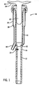
- Fig. 1 shows a teatcup assembly 18 for milking a mammal 20 such as a cow.
- Teat 22 suspending from udder 24 of the mammal extends into the liner.
- Teatcup shell 26 is typically a metal, or plastic, member defining an annular pulsation chamber 28 around liner 16 between the liner and the teatcup shell and having a pulsation port 30 for connection to a pulsator valve, as is known.
- Liner 16 is typically rubber or other flexible material.
- the lower end of milk tube portion 14 of the liner is connection to a claw, for example U.S. Patents 4,537,152 and 5,291,853 , incorporated herein by reference, which in turn supplies milk to a storage vessel.
- vacuum is continuously applied to milk passage 32 within the liner through milk tube portion 14, and vacuum is alternately and cyclically applied to pulsation chamber 28 through port 30, to open and close liner 16 below teat 22, all as is known and for which further reference may be had to the above noted incorporated patents.
- An air vent plug 10 may be inserted through the wall 12 of the milk tube portion 14 of the teat liner, as is known, for example above noted incorporated U.S. Patent 6,055,931 .
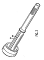
- a teat liner is illustrated in isometric view at 34 in Fig. 2 .
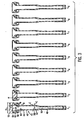
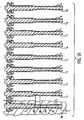
- Fig. 3 illustrates a teatcup liner series in accordance with the invention including in combination a plurality of related teatcup liners comprising n liners L 1 through L n , for example as shown at the nine liners L 1 through L 9 .
- Each liner such as 40 has an upper mouthpiece 42, an intermediate barrel 44 defined by a barrel wall 46, and a lower connecting tube 48.
- the barrel extends along an axial direction 50 for receiving teat 22 inserted axially thereinto through mouthpiece 42.
- the mouthpiece has an upper lip 52 having an aperture 54 therethrough for receiving teat 22.
- Lip 52 has an axial thickness A measured parallel to axial direction 50.
- Barrel wall 46 has axially spaced upper and lower portions 56 and 58.
- Upper portion 56 of barrel wall 46 has a transverse thickness B measured transversely to axial direction 50.
- Lower portion 58 of barrel wall 46 has a transverse thickness C measured transversely to axial direction 50.
- Upper portion 56 of barrel wall 46 has inner surfaces 60 defining a hollow interior with an upper transverse span D thereacross taken transversely to axial direction 50.
- Lower portion 58 of barrel wall 46 has inner surfaces 62 defining a hollow interior with a lower transverse span E thereacross taken transversely to axial direction 50.
- Lip aperture 54 has a transverse dimension taken transversely to axial direction 50 and defining a mouthpiece bore F.
- Mouthpiece 42 has a cavity 64 between lip 52 and barrel 44.
- Cavity 64 has a transverse dimension taken transversely to axial direction 50 and defining a cavity bore G. Cavity 64 has a volume H.
- the noted parameters A through H are varied liner to liner from L 1 through L 9 as indicated in the table below, and as set forth in Fig. 3 .
- the table below gives dimensions for A through G in millimeters (mm).
- the axial thickness A of lip 52 varies from 2.0 mm for liner L 1 to 3.6 mm for liner L 9 .
- the table gives dimensions in cubic inches (in 3 ) for H.
- the liner series is characterized by the following relationships, as illustrated in the table and Fig. 3 : axial thickness A of lip 52 continually increases from L 1 through L n , preferably linearly; transverse thickness of barrel wall 46, including both B and C, continually decreases from L 1 through L n , preferably linearly; the transverse span across the hollow interior, including both D and E, continually increases from L 1 through L n , preferably linearly; mouthpiece bore F continually decreases from L 1 through L n , preferably linearly; cavity bore G continually decreases from L 1 through L n , preferably linearly; cavity volume H continually decreases from L 1 through L n .
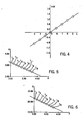
- B is always greater than C
- D is always greater than E, such that both the barrel wall thickness and the noted transverse span are tapered.
- the barrel wall thickness and/or the transverse span may be untapered, i.e. straight.
- the parameter A-B i.e. the difference between A and B, varies as illustrated in the table, namely such difference continually increases from L 1 through L 9 , preferably linearly, as further illustrated in Fig. 4 .
- transverse thickness B of barrel wall 46 versus axial thickness A of lip 52 for liners L 1 through L 9 B decreases as A increases. Further preferably, B decreases linearly with respect to A.
- axial thickness A of lip 52 decreases as mouthpiece bore F increases. Further preferably, A decreases linearly with respect to F.
- axial thickness A of lip 52 decreases as cavity bore G increases. Further preferably, A decreases linearly with respect to G.
- axial thickness A of lip 52 decreases as cavity volume H increases. Further preferably, A decreases linearly with respect to H.
- Liner L 1 provides the highest milk harvest and highest milk speed, but also the greatest liner slip.
- Liner L 9 provides the lowest liner slip and also the lowest milk harvest and milking speed.
- the dairyman can choose the right balance and trade-off for his particular needs. As he moves left to right in Fig. 3 , liner slip reduces as does milk harvest and milking speed. As he moves right to left in Fig. 3 , liner slip increases as does milk harvest and milking speed.
- the liner is preferably round as shown at 66 in Fig. 10 .
- the liner may additionally include a plurality of ribs such as 68, Figs. 11 and 2 , extending axially along the barrel.
- the ribs may be external as shown, and/or internal.
- the liner may be triangular as shown at 70 in Fig. 12 .
- the liner may be square as shown at 72 in Fig. 13 .
- the liner may be oval as shown at 74 in Fig. 14 .
- the liner may be fluted as shown at 76 in Fig. 15 .
- Deflection of lip 52 is varied by parameter A, and may additionally be varied by varying the shore hardness of the lip material.
- Liner barrel tension is varied by varying the noted wall thickness B and C, and may additionally be varied by the addition of the noted ribs and/or changing the cross-section of individual ribs and/or changing liner material and/or changing barrel length.
- the method involves:
Abstract
Description
- The invention relates to teatcup liners for use in a teatcup assembly for milking a mammal. In particular the invention relates to a teatcup liner group with the features of the generic part of claim 1. Further, the invention relates to a manufacturing method for teatcup liners.
- As known in the prior art, a plurality of teatcups are connected to respective teats suspending from the udder of a mammal such as a cow. Each teatcup assembly has a teatcup liner or inflation around a respective teat and defining a milk flow passage within the liner below the teat, and a pulsation chamber outside the liner between the liner and the teatcup shell, for example
U.S. Patents 4,269,143 ,4,530,307 ,5,178,095 ,5,218,924 ,6,055,931 , all incorporated herein by reference. The system has a milking cycle with an on portion and an off portion. Milk flows from the teat towards a milking claw during the on portion, and then to a storage vessel. During the off portion, the liner is collapsed around the teat, to aid in the circulation of body fluids. Vacuum is continuously applied to the milk flow passage within the liner. Vacuum is alternately and cyclically applied to the pulsation chamber between the liner and the teatcup shell, to open and close the liner, all is known. - In the prior art forming the starting point of the invention (
GB-A-975,757 - The object of the present invention is to provide the dairyman with selectivity in choosing between the trade-off of liner slip versus milk harvest and milking speed.
- The above mentioned object is met with a teatcup liner group according to claim 1. Continually varying from linter to liner is preferably linearly varying from liner to liner.
- During continuing development efforts, various relationships have been discovered between various liner parameters, and in accordance therewith, a liner series has been developed having at least one and preferably a plurality of parameters which vary liner to liner in optimized manner to afford the noted selectivity.
- Preferred further features are the subject matter of the
dependent claims 2 to 13. They are all described in the detailed description of preferred embodiment of the invention. - Further, the invention relates to a method for making a teatcup liner series that has in combination a plurality of related teatcup liners. The preferred method according to the invention is described in
claim 14. The manufacturing method according to the invention provides a particularly cost effective means for producing the liner series. - Further modifications and improvements of the method according to the invention are described in the further dependent claims, namely claim 15.
- Now, preferred embodiments of the invention are described in detail with reference to the drawings. In the drawings
- Fig. 1
- is taken from
U.S. Patent 6,055,931 and is a side view partially in section of a teatcup assembly including a teatcup liner for milking a mammal. - Fig. 2
- is an isometric view of a teatcup liner.
- Fig. 3
- shows a teatcup liner series in accordance with the invention.
- Fig. 4
- is a graphical plot of a selected parameter which varies in accordance with the invention.
- Fig. 5
- is a graphical plot of the variance of a pair of parameters versus each other in accordance with the invention.
- Fig. 6
- is a graphical plot of the variance of another pair of parameters versus each other in accordance with the invention.
- Fig. 7
- is a graphical plot of the variance of another pair of parameters versus each other in accordance with the invention.
- Fig. 8
- is a graphical plot of the variance of another pair of parameters versus each other in accordance with the invention.
- Fig. 9
- is a graphical plot of the variance of another pair of parameters versus each other in accordance with the invention.
- Fig. 10
- is a cross-sectional view of a liner.
- Fig. 11
- is like
Fig. 10 and shows another embodiment. - Fig. 12
- is like
Fig. 10 and shows another embodiment. - Fig. 13
- is like
Fig. 10 and shows another embodiment. - Fig. 14
- is like
Fig. 10 and shows another embodiment. - Fig. 15
- is like
Fig. 10 and shows another embodiment. - Fig. 16
- is like
Fig. 3 and illustrates a manufacturing method in accordance with the invention. -
Fig. 1 shows ateatcup assembly 18 for milking amammal 20 such as a cow.Teat 22 suspending fromudder 24 of the mammal extends into the liner. Teatcupshell 26 is typically a metal, or plastic, member defining anannular pulsation chamber 28 aroundliner 16 between the liner and the teatcup shell and having apulsation port 30 for connection to a pulsator valve, as is known.Liner 16 is typically rubber or other flexible material. The lower end ofmilk tube portion 14 of the liner is connection to a claw, for exampleU.S. Patents 4,537,152 and5,291,853 , incorporated herein by reference, which in turn supplies milk to a storage vessel. As noted above, vacuum is continuously applied tomilk passage 32 within the liner throughmilk tube portion 14, and vacuum is alternately and cyclically applied topulsation chamber 28 throughport 30, to open andclose liner 16 belowteat 22, all as is known and for which further reference may be had to the above noted incorporated patents. Anair vent plug 10 may be inserted through thewall 12 of themilk tube portion 14 of the teat liner, as is known, for example above noted incorporatedU.S. Patent 6,055,931 . For further background, a teat liner is illustrated in isometric view at 34 inFig. 2 . -
Fig. 3 illustrates a teatcup liner series in accordance with the invention including in combination a plurality of related teatcup liners comprising n liners L1 through Ln, for example as shown at the nine liners L1 through L9. Each liner such as 40 has anupper mouthpiece 42, anintermediate barrel 44 defined by abarrel wall 46, and a lower connectingtube 48. The barrel extends along anaxial direction 50 for receivingteat 22 inserted axially thereinto throughmouthpiece 42. The mouthpiece has anupper lip 52 having anaperture 54 therethrough for receivingteat 22.Lip 52 has an axial thickness A measured parallel toaxial direction 50.Barrel wall 46 has axially spaced upper andlower portions Upper portion 56 ofbarrel wall 46 has a transverse thickness B measured transversely toaxial direction 50.Lower portion 58 ofbarrel wall 46 has a transverse thickness C measured transversely toaxial direction 50.Upper portion 56 ofbarrel wall 46 hasinner surfaces 60 defining a hollow interior with an upper transverse span D thereacross taken transversely toaxial direction 50.Lower portion 58 ofbarrel wall 46 hasinner surfaces 62 defining a hollow interior with a lower transverse span E thereacross taken transversely toaxial direction 50.Lip aperture 54 has a transverse dimension taken transversely toaxial direction 50 and defining a mouthpiece boreF. Mouthpiece 42 has acavity 64 betweenlip 52 andbarrel 44. -
Cavity 64 has a transverse dimension taken transversely toaxial direction 50 and defining a cavitybore G. Cavity 64 has a volume H. - In one preferred embodiment, the noted parameters A through H are varied liner to liner from L1 through L9 as indicated in the table below, and as set forth in
Fig. 3 . The table below gives dimensions for A through G in millimeters (mm). For example, the axial thickness A oflip 52 varies from 2.0 mm for liner L1 to 3.6 mm for liner L9. The table gives dimensions in cubic inches (in3) for H.Table LINER L1 L2 L3 L4 L5 L6 L7 L8 L9 A(mm) 2.0 2.2 2.4 2.6 2.8 3 3.2 3.4 3.6 B(mm) 3.2 3.1 3.0 2.9 2.8 2.7 2.6 2.5 2.4 C(mm) 2.9 2.8 2.7 2.6 2.5 2.4 2.3 2.2 2.1 D(mm) 20.2 20.4 20.6 20.8 21 21.2 21.4 21.6 21.8 E(mm) 18.9 19.1 19.3 19.5 19.7 19.9 20.1 20.3 20.5 F(mm) 20.4 20.3 20.2 20.1 20.0 19.9 19.8 19.7 19.6 G(mm) 52.95 52.65 52.25 51.85 51.45 51.05 50.65 50.25 49.85 H(in3) 1.368 1.353 1.336 1.318 1.301 1.283 1.265 1.248 1.230 A-B(mm) -1.2 -0.9 -0.6 -0.3 0 0.3 0.6 0.9 1.2 - The liner series is characterized by the following relationships, as illustrated in the table and
Fig. 3 : axial thickness A oflip 52 continually increases from L1 through Ln, preferably linearly; transverse thickness ofbarrel wall 46, including both B and C, continually decreases from L1 through Ln, preferably linearly; the transverse span across the hollow interior, including both D and E, continually increases from L1 through Ln, preferably linearly; mouthpiece bore F continually decreases from L1 through Ln, preferably linearly; cavity bore G continually decreases from L1 through Ln, preferably linearly; cavity volume H continually decreases from L1 through Ln. - In the preferred embodiment, B is always greater than C, and D is always greater than E, such that both the barrel wall thickness and the noted transverse span are tapered. In alternate embodiments, the barrel wall thickness and/or the transverse span may be untapered, i.e. straight.
- Further, in the preferred embodiment, the parameter A-B, i.e. the difference between A and B, varies as illustrated in the table, namely such difference continually increases from L1 through L9, preferably linearly, as further illustrated in
Fig. 4 . - Further, in the preferred embodiment, in a plot,
Fig. 5 , of transverse thickness B ofbarrel wall 46 versus axial thickness A oflip 52 for liners L1 through L9, B decreases as A increases. Further preferably, B decreases linearly with respect to A. - Further in the preferred embodiment, in a plot,
Fig. 6 , of transverse span D versus axial thickness A oflip 52 for L1 through L9, D decreases as A increases. Further preferably, D decreases linearly with respect to A. - Further in the preferred embodiment, in a plot,
Fig. 7 , of axial thickness A oflip 52 versus mouthpiece bore F for L1 through L9, axial thickness A decreases as mouthpiece bore F increases. Further preferably, A decreases linearly with respect to F. - Further in the preferred embodiment, in a plot,
Fig. 8 , of axial thickness A oflip 52 versus cavity bore G for L1 through L9, axial thickness A decreases as cavity bore G increases. Further preferably, A decreases linearly with respect to G. - Further in the preferred embodiment, in a plot,
Fig. 9 , of axial thickness A oflip 52 versus cavity volume H for L1 through L9, axial thickness A decreases as cavity volume H increases. Further preferably, A decreases linearly with respect to H. - The disclosed combination enables selection of desired milking characteristics. Liner L1 provides the highest milk harvest and highest milk speed, but also the greatest liner slip. Liner L9 provides the lowest liner slip and also the lowest milk harvest and milking speed. The dairyman can choose the right balance and trade-off for his particular needs. As he moves left to right in
Fig. 3 , liner slip reduces as does milk harvest and milking speed. As he moves right to left inFig. 3 , liner slip increases as does milk harvest and milking speed. - The liner is preferably round as shown at 66 in
Fig. 10 . The liner may additionally include a plurality of ribs such as 68,Figs. 11 and2 , extending axially along the barrel. The ribs may be external as shown, and/or internal. The liner may be triangular as shown at 70 inFig. 12 . The liner may be square as shown at 72 inFig. 13 . The liner may be oval as shown at 74 inFig. 14 . The liner may be fluted as shown at 76 inFig. 15 . - The various combinations of parameters providing the noted selectivity of milking characteristics are set forth in the claims. Deflection of
lip 52 is varied by parameter A, and may additionally be varied by varying the shore hardness of the lip material. Liner barrel tension is varied by varying the noted wall thickness B and C, and may additionally be varied by the addition of the noted ribs and/or changing the cross-section of individual ribs and/or changing liner material and/or changing barrel length. - There is further provided a simple and particularly cost effective and economical manufacturing method for making the teatcup liner series.
- The method involves:
- forming a first of the liners L1 in a
mold 80,Fig. 16 , having a first removable core C1 inserted therein, the mold forming the outer profile surface 82 of liner L1, the core C1 forming the inner profile surface 84 of liner L1; forming a second of the liners L2 in thesame mold 80 having a second removable core C2 inserted therein, themold 80 forming the outer profile surface 86 of liner L2, the core C2 forming the inner profile surface 88 of liner L2; forming the remainder of the liners through Ln, e.g. L3 through L9, in thesame mold 80 having respective removable cores through Cn, e.g. C3 through C9, inserted therein, themold 80 forming the outer profile surface of the liners through Ln, the cores through Cn forming the inner profile surfaces of the liners through Ln, e.g. cores C3 through C9 form the inner profile surfaces for liners L3 through L9, respectively. Thesame mold 80 is used for each of the liners L1 through L9. The outer profile surface is the same for each of liners L1 through L9. Different cores C1 through C9 are used for liners L1 through L9. The inner profile surface is different from liner to liner according to C1 through C9. Any or all or some combination of the noted parameters A-H are varied liner to liner according to C1 through C9. The cores change a selected dimensional parameter or parameters. This is particularly desirable from a manufacturing standpoint because of the savings in tooling cost by using a single mold to produce the liner series, rather than multiple molds, i.e. one for each liner. Instead, different cores are used to provide the variance liner to liner in the series. Cores are significantly less expensive than a mold.
Claims (15)
- A teatcup liner group comprising a plurality of teatcup liners (40),
each liner (40) having an upper mouthpiece (42), an intermediate barrel (44) defined by a barrel wall (46), and a lower connecting tube (48), said barrel (44) extending along an axial direction (50) for receiving a teat (22) inserted axially thereinto through said mouthpiece (42), said mouthpiece (42) having an upper lip (52) having an aperture (54) therethrough for receiving said teat (22),
wherein the liners (40) of the group are different from each other in at least one parameter,
characterized in that
the teatcup liners (40) of the group are combined to form a teatcup liner series, said teatcup liner series comprising a plurality of n liners L1 through Ln with n being an integer greater than 2, the liners L1 through Ln of the liner series having at least two selected parameters continually varying from liner to liner,
the lip (52) of a liner (40) has an axial thickness (A) measured parallel to said axial direction (50), one of said selected parameters is the axial thickness (A) of the lip (52) and the axial thickness (A) of the lip (52) continually increases from the first liner L1 through the last liner Ln of the liner series, and
the barrel wall (46) of a liner (40) has a transverse thickness (B; C) measured transversely to said axial direction (50),
another one of said selected parameters is the transverse thickness (B; C) of the barrel wall (46) of the liner (40) and
the transverse thickness (B; C) of the barrel wall (46) continually decreases from the first liner L1 through the last liner Ln of the liner series. - Teatcup liner series according to claim 1, characterized in that
the selected parameters are linearly varied from liner to liner. - Teatcup liner series according to claim 1 or 2, characterized in that said barrel wall (46) has axially spaced upper and lower portions (56, 58), said upper (56) portion of said barrel wall (46) has a transverse thickness (B) measured transversely to said axial direction (50),
said lower portion (58) of said barrel wall (46) has a transverse thickness (C) measured transversely to said axial direction (50),
said upper portion (56) of said barrel wall (46) has a greater transverse thickness than said lower portion (58) of said barrel wall (46) for each of said liners L1 through Ln,
one of said selected parameters is said transverse thickness (B) of said upper portion (56) of said barrel wall (46),
another one of said selected parameters is said transverse thickness (C) of said lower portion (58) of said barrel wall (46),
said transverse thickness (B) of said upper portion (56) of said barrel wall (46) continually decreases from L1 through Ln; and said transverse thickness (C) of said lower portion (58) of said barrel wall (46) continually decreases from L1 through Ln. - Teatcup liner series according to any one of the preceding claims, characterized in that
said barrel wall (46) has inner surfaces (60, 62) defining a hollow interior with a transverse span (D; E) thereacross taken transversely to said axial direction (50),
one of said selected parameters is said transverse span (D; E), and
said transverse span (D; E) continually increases from L1 through Ln. - Teatcup liner series according to claim 4, characterized in that
said barrel wall (46) is annular, and said transverse span (D; E) is the inner diameter of said barrel wall (46). - Teatcup liner series according to claim 4 or 5, characterized in that
said barrel wall (46) has axially spaced upper and lower portions (56, 58),
said upper portion (56) of said barrel wall (46) has inner surfaces (60) defining a hollow interior with an upper transverse span (D) thereacross taken transversely to said axial direction (50),
said lower portion (58) of said barrel wall (46) has inner surfaces (62) defining a hollow interior with a lower transverse span (E) thereacross taken transversely to said axial direction (50),
said upper transverse span (D) is greater than said lower transverse span (E) for each of said liners L1 through Ln,
one of said selected parameters is said upper transverse span (D),
another one of said selected parameters is said lower transverse span (E),
said upper transverse span (D) continually increases from L1 through Ln, and
said lower transverse span (E) continually increases from L1 through Ln. - Teatcup liner series according to any one of the preceding claims, characterized in that
said lip aperture (54) has a transverse dimension taken transversely to said axial direction (50) and defining a mouthpiece bore (F),
one of said selected parameters is said mouthpiece bore (F), and
said mouthpiece bore (F) continually decreases from L1 through Ln. - Teatcup liner series according to any one of the preceding claims, characterized in that
said mouthpiece (42) has a cavity (64) between said lip (52) and said barrel (44), and said cavity (64) has a transverse dimension taken transversely to said axial direction (50) and defining a cavity bore (G),
one of said selected parameters is said cavity bore (G), and
said cavity bore (G) continually decreases from L1 through Ln. - Teatcup liner series according to any one of the preceding claims, characterized in that
said mouthpiece (42) has a cavity (64) between said lip (52) and said barrel (44), said cavity (64) having a volume (H),
one of said selected parameters is said cavity volume (H), and
said cavity volume (H) continually decreases from L1 through Ln. - Teatcup liner series according to any one of the preceding claims, characterized in that
one of said selected parameters is the difference between said axial thickness (A) of said lip (52) and said transverse thickness (B) of said barrel wall (46), and said difference continually increases from L1 through Ln. - Teatcup liner series according to any one of the preceding claims, characterized in that
wherein said transverse thickness (B) decreases linearly with respect to said axial thickness (A). - Teatcup liner series according to any one of the preceding claims, characterized in that
each said liner (66) is round in transverse cross-section taken transversely to said axial direction (50),
or, each said liner (70) is triangular in transverse cross-section taken transversely to said axial direction (50),
or, each said liner (72) is square in transverse cross-section taken transversely to said axial direction (50),
or, each said liner is polygonal in transverse cross-section taken transversely to said axial direction (50),
or, each said liner (74) is oval in transverse cross-section taken transversely to said axial direction (50),
or, each said liner (76) is fluted. - Teatcup liner series according to any one of the preceding claims, characterized in that
each said liner has a plurality of ribs (68) extending axially therealong. - A method for making a teatcup liner series having in combination a plurality of related teatcup liners, said teatcup liner series comprising n liners L1 through Ln with n being an integer greater than 2,
each liner (40) having an upper mouthpiece (42), an intermediate barrel (44) defined by a barrel wall (46), and a lower connecting tube (48),
said barrel (44) extending along an axial direction (50) for receiving a teat (22) inserted axially thereinto through said mouthpiece (42),
said mouthpiece (42) having an upper lip (52) having an aperture (54) therethrough for receiving said teat (22),
each liner (40) having an outer profile surface (82) and an inner profile surface (84),
said method comprising the following method steps:forming a first of said liners L1 in a mold having a first removable core C1 inserted therein, said mold forming the outer profile surface of liner L1, said core C1 forming the inner profile surface of liner L1;forming a second of said liners L2 in the same said mold having a second removable core C2 inserted therein, said mold forming the outer profile surface of liner L2, said core C2 forming the inner profile surface of liner L2;forming the remainder of said liners through Ln in the same said mold having respective removable cores through Cn inserted therein, said mold forming the outer profile surface of said liners through Ln, said cores through Cn forming the inner profile surfaces of the liners through Ln;wherein the same said mold is used for all liners L1 through Ln, the outer profile surface is the same for each of said liners L1 through Ln, andthe inner profile surface is different liner to liner according to C1 through Cn, - Method according to claim 14, characterized in that said lip has an axial thickness measured parallel to said axial direction, and one of said selected parameters is said axial thickness of said lip, and/or said barrel wall has a transverse thickness measured transversely to said axial direction, and one of said selected parameters is said transverse thickness of said barrel wall, and/or
said barrel wall has inner surfaces defining a hollow interior with a transverse span thereacross taken transversely to said axial direction and one of said selected parameters is said transverse span" and/or
said lip aperture has transverse dimension taken transversely to said axial direction and defining a mouthpiece bore, and one of said selected parameters is said mouthpiece bore, and/or
said mouthpiece has a cavity between said lip and said barrel, said cavity has a transverse dimension taken transversely to said axial direction and defining a cavity bore, and one of said selected parameters is said cavity bore, and/or said mouthpiece has a cavity between said lip and said barrel, said cavity has a volume, and one of said selected parameters is said cavity volume.
Applications Claiming Priority (2)
| Application Number | Priority Date | Filing Date | Title |
|---|---|---|---|
| US10/071,332 US6631694B1 (en) | 2002-02-08 | 2002-02-08 | Teatcup liner series |
| US71332 | 2002-02-08 |
Publications (3)
| Publication Number | Publication Date |
|---|---|
| EP1334656A1 EP1334656A1 (en) | 2003-08-13 |
| EP1334656B1 EP1334656B1 (en) | 2008-07-23 |
| EP1334656B2 true EP1334656B2 (en) | 2013-05-22 |
Family
ID=27610542
Family Applications (1)
| Application Number | Title | Priority Date | Filing Date |
|---|---|---|---|
| EP03002906.0A Expired - Lifetime EP1334656B2 (en) | 2002-02-08 | 2003-02-10 | Teatcup liner series |
Country Status (11)
| Country | Link |
|---|---|
| US (2) | US6631694B1 (en) |
| EP (1) | EP1334656B2 (en) |
| JP (1) | JP4048485B2 (en) |
| AT (1) | ATE401783T1 (en) |
| AU (1) | AU2003200304B2 (en) |
| CA (1) | CA2418505C (en) |
| DE (1) | DE60322283D1 (en) |
| ES (1) | ES2310629T5 (en) |
| IL (1) | IL154313A (en) |
| MX (1) | MXPA03001155A (en) |
| NZ (1) | NZ524001A (en) |
Families Citing this family (25)
| Publication number | Priority date | Publication date | Assignee | Title |
|---|---|---|---|---|
| US6631694B1 (en) * | 2002-02-08 | 2003-10-14 | Mofazzal H. Chowdhury | Teatcup liner series |
| US6776120B1 (en) * | 2002-02-08 | 2004-08-17 | Mofazzal H. Chowdhury | Controlled collapse teatcup liner |
| US6857389B2 (en) * | 2002-06-21 | 2005-02-22 | Silicone Plastics, Inc. | Teat cup system |
| US6997136B1 (en) | 2003-03-21 | 2006-02-14 | Avon Hi-Life, Inc. | Teat cup assembly |
| US7290498B2 (en) * | 2004-06-29 | 2007-11-06 | Lauren Agrisystems, Ltd. | Vent plug for milking liner |
| CA2570327C (en) * | 2004-06-29 | 2013-11-26 | Lauren Agrisystems, Ltd. | Milking liner |
| US7293527B2 (en) * | 2004-06-29 | 2007-11-13 | Lauren Agrisystems, Ltd. | Vent plug for milking liner |
| GB0423132D0 (en) * | 2004-10-18 | 2004-11-17 | Avon Polymer Prod Ltd | Milking apparatus and method |
| EP1795068A1 (en) | 2005-12-06 | 2007-06-13 | Bou-Matic Technologies Corporation | Valved teatcup assembly |
| DE602006004291D1 (en) * | 2006-01-06 | 2009-01-29 | Bou Matic Technologies Corp | teat cups |
| GB0716800D0 (en) * | 2007-08-29 | 2007-10-10 | Avon Polymer Prod Ltd | Milking apparatus and method |
| DE102008056545A1 (en) * | 2008-11-10 | 2010-05-27 | Gea Westfaliasurge Gmbh | Cleaning unit for cleaning at least a head portion of a milking cup |
| US8302561B2 (en) * | 2009-08-11 | 2012-11-06 | Lauren Agrisystems, Ltd. | Teat cup shell |
| CN102655738B (en) * | 2009-12-02 | 2014-09-17 | 岸弘聚合物有限公司 | Mouthpiece-vented teat cup inflation |
| US8056505B2 (en) * | 2009-12-08 | 2011-11-15 | Lauren Agrisystems, Ltd. | Vent for milking liner |
| US8375894B2 (en) | 2010-07-15 | 2013-02-19 | Mofazzal H. Chowdhury | Teatcup liner series with varying mouthpiece flexibility |
| ES2623507T3 (en) * | 2012-05-07 | 2017-07-11 | Delaval Holding Ab | Linchpin |
| US9439391B2 (en) | 2012-12-07 | 2016-09-13 | Lauren Agrisystems, Ltd. | Dairy milking devices and methods |
| WO2014135226A1 (en) * | 2013-03-08 | 2014-09-12 | Fuchs, Willi | A mechanical milking system, device, procedure and use for dairy animals that allows inhibiting, and/or preventing the presence of infections due to mastitis, with surface fungicide, antibacterial, antivirus, and microbicide properties, wherein the surface comprises specific surface rugosity formed by a special alloy with copper content mostly |
| US9408367B2 (en) * | 2013-10-28 | 2016-08-09 | Delaval Holding Ab | Teatcup liner with enhanced teat massage |
| BR112016009385B1 (en) * | 2013-10-28 | 2020-09-24 | Delaval Holding Ab | TILER LINING |
| DE102014101613A1 (en) * | 2014-02-10 | 2015-08-13 | Happel WDA Besitz GbR (vertretungsberechtigter Gesellschafter: Werner Happel, 87654 Friesenried) | liner |
| BR112017009547B1 (en) * | 2014-11-07 | 2022-02-01 | Gea Farm Technologies Gmbh | short tube of milk |
| USD830649S1 (en) * | 2016-01-28 | 2018-10-09 | Gea Farm Technologies, Inc. | Vent protecting stiffener for a dairy animal milker unit tube |
| US20220312719A1 (en) * | 2021-03-31 | 2022-10-06 | Beco Dairy Automation Inc. | Teat Cup Liner, Apparatus Including the Same, and Methods of Making and Using the Same |
Citations (1)
| Publication number | Priority date | Publication date | Assignee | Title |
|---|---|---|---|---|
| US4141319A (en) † | 1975-04-28 | 1979-02-27 | Kuenzler & Co. | Rubber teat holder for milking cups |
Family Cites Families (22)
| Publication number | Priority date | Publication date | Assignee | Title |
|---|---|---|---|---|
| GB975757A (en) | 1961-01-25 | 1964-11-18 | Joseph Holgate Cooper | Improvements in and relating to liners for milking machines |
| US3096740A (en) | 1961-08-25 | 1963-07-09 | Noorlander Daniel Olie | Teat cup liner construction |
| US3289634A (en) | 1965-06-25 | 1966-12-06 | Sta Rite Products Inc | Predetermined collapse type milking machine inflation |
| US3659558A (en) | 1970-03-23 | 1972-05-02 | Daniel O Noorlander | Teat cup inflation |
| US3967587A (en) | 1972-12-13 | 1976-07-06 | Noorlander Daniel O | Teat cup inflation |
| US4269143A (en) | 1977-09-16 | 1981-05-26 | Dec International, Inc. | Teat cup assembly |
| US4530307A (en) | 1982-10-06 | 1985-07-23 | Dec International, Inc. | Teat cup inflation |
| US4537152A (en) | 1984-06-01 | 1985-08-27 | Dec International, Inc. | Milking claw |
| US4610220A (en) | 1985-05-06 | 1986-09-09 | Edward Goldberg | Inflation for a teat cup |
| US5178095A (en) | 1991-06-13 | 1993-01-12 | Dec International, Inc. | Milking system with positive pressure on thin liner |
| US5218924A (en) | 1992-03-19 | 1993-06-15 | Dec International, Inc. | Milking system with variable pressure source |
| US5291853A (en) | 1993-04-08 | 1994-03-08 | Dec International, Inc. | Top unloaded milking claw |
| US5493995A (en) | 1994-05-16 | 1996-02-27 | Alfa Laval Agri, Inc. | Collapsing teat cup liner with tapering barrel wall |
| US5482004A (en) | 1994-05-16 | 1996-01-09 | Alfa Laval Agri, Inc. | Collapsible teat liner with reinforced barrel |
| US5752462A (en) | 1995-05-22 | 1998-05-19 | Iba, Inc. | Teat cup inflation |
| SE9604053D0 (en) | 1996-11-05 | 1996-11-05 | Alfa Laval Agri Ab | Teat rubber and process for the manufacture of a teat rubber |
| NZ507213A (en) | 1998-03-23 | 2001-12-21 | Silclear Ltd | Tapered wall teat cup liner for a milking machine |
| US6039001A (en) | 1998-05-19 | 2000-03-21 | Dec International, Inc. | Teatcup liner with desired mouthpiece chamber vacuum |
| US6055931A (en) | 1998-10-13 | 2000-05-02 | Dec International, Inc. | Clog resistant air vent plug for teatcup liner |
| US6308656B1 (en) | 1999-12-23 | 2001-10-30 | Constance J. Milbrath | Modular teat cup assembly |
| US6435132B1 (en) | 1999-12-23 | 2002-08-20 | Constance J. Milbrath | Teat cup assembly |
| US6631694B1 (en) * | 2002-02-08 | 2003-10-14 | Mofazzal H. Chowdhury | Teatcup liner series |
-
2002
- 2002-02-08 US US10/071,332 patent/US6631694B1/en not_active Expired - Lifetime
-
2003
- 2003-01-31 AU AU2003200304A patent/AU2003200304B2/en not_active Expired
- 2003-02-04 NZ NZ524001A patent/NZ524001A/en not_active IP Right Cessation
- 2003-02-05 CA CA002418505A patent/CA2418505C/en not_active Expired - Lifetime
- 2003-02-06 IL IL154313A patent/IL154313A/en unknown
- 2003-02-06 JP JP2003029564A patent/JP4048485B2/en not_active Expired - Fee Related
- 2003-02-07 MX MXPA03001155A patent/MXPA03001155A/en active IP Right Grant
- 2003-02-10 ES ES03002906T patent/ES2310629T5/en not_active Expired - Lifetime
- 2003-02-10 DE DE60322283T patent/DE60322283D1/en not_active Expired - Lifetime
- 2003-02-10 AT AT03002906T patent/ATE401783T1/en not_active IP Right Cessation
- 2003-02-10 EP EP03002906.0A patent/EP1334656B2/en not_active Expired - Lifetime
- 2003-06-19 US US10/600,166 patent/US6796272B1/en not_active Expired - Lifetime
Patent Citations (1)
| Publication number | Priority date | Publication date | Assignee | Title |
|---|---|---|---|---|
| US4141319A (en) † | 1975-04-28 | 1979-02-27 | Kuenzler & Co. | Rubber teat holder for milking cups |
Non-Patent Citations (5)
| Title |
|---|
| DECLARATION FROM MR.JAKOB MAIER † |
| DISSERTATION VON DIETER MAXIMILIAN SCHAETZL, INSTITUT FUER PHYSIOLOGIE FORSCHUNGSZENTRUM FUER MILCH UND LEBENSMITTEL WEIHENSTEPHAN, TU MUENCHEN, JANUAR 2000 † |
| GEBRAUCHSHINWEISE STIMULOR-ZITZENGUMMI † |
| INSTALLATION INSTRUCTIONS FROM WESTFALIA-LANDTECHNIK. † |
| SCHAETZEL,WORSTHOFF & FISCHER,"ZUM EINFLUSS DER ZITZENGUMMI-EIGENSCHAFTEN SHOREHAERTE UND WANDSTAERKE AUF DEN EINFALTDRUCK UND DIE MILCHABGABE VON KUEHEN", IN MILCHWISSENSCHAFT 54(4) 1999, PAGES 183-187 † |
Also Published As
| Publication number | Publication date |
|---|---|
| AU2003200304B2 (en) | 2009-07-02 |
| JP4048485B2 (en) | 2008-02-20 |
| AU2003200304A1 (en) | 2003-08-28 |
| ATE401783T1 (en) | 2008-08-15 |
| CA2418505C (en) | 2009-08-04 |
| EP1334656B1 (en) | 2008-07-23 |
| ES2310629T3 (en) | 2009-01-16 |
| EP1334656A1 (en) | 2003-08-13 |
| CA2418505A1 (en) | 2003-08-08 |
| JP2003235374A (en) | 2003-08-26 |
| ES2310629T5 (en) | 2013-10-11 |
| IL154313A (en) | 2008-07-08 |
| US6796272B1 (en) | 2004-09-28 |
| MXPA03001155A (en) | 2004-09-06 |
| US6631694B1 (en) | 2003-10-14 |
| IL154313A0 (en) | 2003-09-17 |
| NZ524001A (en) | 2004-09-24 |
| DE60322283D1 (en) | 2008-09-04 |
Similar Documents
| Publication | Publication Date | Title |
|---|---|---|
| EP1334656B2 (en) | Teatcup liner series | |
| US6776120B1 (en) | Controlled collapse teatcup liner | |
| US9510555B2 (en) | Teatcup liner series with varying mouthpiece flexibility | |
| US8627785B2 (en) | Mouthpiece-vented teat cup inflation | |
| EP2192831B1 (en) | Teat cup liner | |
| EP1902613B1 (en) | Teat cup inflation | |
| US6055931A (en) | Clog resistant air vent plug for teatcup liner | |
| AU2016256705B2 (en) | Teatcup liner series with varying mouthpiece flexibility | |
| AU2015203022B2 (en) | Teatcup liner series with varying mouthpiece flexibility | |
| US10470429B2 (en) | Teat cup liner |
Legal Events
| Date | Code | Title | Description |
|---|---|---|---|
| PUAI | Public reference made under article 153(3) epc to a published international application that has entered the european phase |
Free format text: ORIGINAL CODE: 0009012 |
|
| AK | Designated contracting states |
Designated state(s): AT BE BG CH CY CZ DE DK EE ES FI FR GB GR HU IE IT LI LU MC NL PT SE SI SK TR |
|
| AX | Request for extension of the european patent |
Extension state: AL LT LV MK RO |
|
| 17P | Request for examination filed |
Effective date: 20040203 |
|
| AKX | Designation fees paid |
Designated state(s): AT BE BG CH CY CZ DE DK EE ES FI FR GB GR HU IE IT LI LU MC NL PT SE SI SK TR |
|
| RAP1 | Party data changed (applicant data changed or rights of an application transferred) |
Owner name: CHOWDHURY, MOFAZZAL H. |
|
| 17Q | First examination report despatched |
Effective date: 20060804 |
|
| GRAP | Despatch of communication of intention to grant a patent |
Free format text: ORIGINAL CODE: EPIDOSNIGR1 |
|
| GRAS | Grant fee paid |
Free format text: ORIGINAL CODE: EPIDOSNIGR3 |
|
| GRAA | (expected) grant |
Free format text: ORIGINAL CODE: 0009210 |
|
| AK | Designated contracting states |
Kind code of ref document: B1 Designated state(s): AT BE BG CH CY CZ DE DK EE ES FI FR GB GR HU IE IT LI LU MC NL PT SE SI SK TR |
|
| REG | Reference to a national code |
Ref country code: GB Ref legal event code: FG4D |
|
| REG | Reference to a national code |
Ref country code: CH Ref legal event code: EP |
|
| REG | Reference to a national code |
Ref country code: IE Ref legal event code: FG4D |
|
| REF | Corresponds to: |
Ref document number: 60322283 Country of ref document: DE Date of ref document: 20080904 Kind code of ref document: P |
|
| REG | Reference to a national code |
Ref country code: SE Ref legal event code: TRGR |
|
| NLV1 | Nl: lapsed or annulled due to failure to fulfill the requirements of art. 29p and 29m of the patents act | ||
| REG | Reference to a national code |
Ref country code: ES Ref legal event code: FG2A Ref document number: 2310629 Country of ref document: ES Kind code of ref document: T3 |
|
| PG25 | Lapsed in a contracting state [announced via postgrant information from national office to epo] |
Ref country code: PT Free format text: LAPSE BECAUSE OF FAILURE TO SUBMIT A TRANSLATION OF THE DESCRIPTION OR TO PAY THE FEE WITHIN THE PRESCRIBED TIME-LIMIT Effective date: 20081223 Ref country code: NL Free format text: LAPSE BECAUSE OF FAILURE TO SUBMIT A TRANSLATION OF THE DESCRIPTION OR TO PAY THE FEE WITHIN THE PRESCRIBED TIME-LIMIT Effective date: 20080723 |
|
| PG25 | Lapsed in a contracting state [announced via postgrant information from national office to epo] |
Ref country code: BG Free format text: LAPSE BECAUSE OF FAILURE TO SUBMIT A TRANSLATION OF THE DESCRIPTION OR TO PAY THE FEE WITHIN THE PRESCRIBED TIME-LIMIT Effective date: 20081023 Ref country code: FI Free format text: LAPSE BECAUSE OF FAILURE TO SUBMIT A TRANSLATION OF THE DESCRIPTION OR TO PAY THE FEE WITHIN THE PRESCRIBED TIME-LIMIT Effective date: 20080723 Ref country code: SI Free format text: LAPSE BECAUSE OF FAILURE TO SUBMIT A TRANSLATION OF THE DESCRIPTION OR TO PAY THE FEE WITHIN THE PRESCRIBED TIME-LIMIT Effective date: 20080723 Ref country code: AT Free format text: LAPSE BECAUSE OF FAILURE TO SUBMIT A TRANSLATION OF THE DESCRIPTION OR TO PAY THE FEE WITHIN THE PRESCRIBED TIME-LIMIT Effective date: 20080723 |
|
| PG25 | Lapsed in a contracting state [announced via postgrant information from national office to epo] |
Ref country code: DK Free format text: LAPSE BECAUSE OF FAILURE TO SUBMIT A TRANSLATION OF THE DESCRIPTION OR TO PAY THE FEE WITHIN THE PRESCRIBED TIME-LIMIT Effective date: 20080723 Ref country code: EE Free format text: LAPSE BECAUSE OF FAILURE TO SUBMIT A TRANSLATION OF THE DESCRIPTION OR TO PAY THE FEE WITHIN THE PRESCRIBED TIME-LIMIT Effective date: 20080723 |
|
| PLBI | Opposition filed |
Free format text: ORIGINAL CODE: 0009260 |
|
| PLAX | Notice of opposition and request to file observation + time limit sent |
Free format text: ORIGINAL CODE: EPIDOSNOBS2 |
|
| PG25 | Lapsed in a contracting state [announced via postgrant information from national office to epo] |
Ref country code: SK Free format text: LAPSE BECAUSE OF FAILURE TO SUBMIT A TRANSLATION OF THE DESCRIPTION OR TO PAY THE FEE WITHIN THE PRESCRIBED TIME-LIMIT Effective date: 20080723 Ref country code: CZ Free format text: LAPSE BECAUSE OF FAILURE TO SUBMIT A TRANSLATION OF THE DESCRIPTION OR TO PAY THE FEE WITHIN THE PRESCRIBED TIME-LIMIT Effective date: 20080723 |
|
| 26 | Opposition filed |
Opponent name: SILICONFORM GMBH & CO. KG Effective date: 20090423 |
|
| PG25 | Lapsed in a contracting state [announced via postgrant information from national office to epo] |
Ref country code: MC Free format text: LAPSE BECAUSE OF NON-PAYMENT OF DUE FEES Effective date: 20090228 |
|
| PLAF | Information modified related to communication of a notice of opposition and request to file observations + time limit |
Free format text: ORIGINAL CODE: EPIDOSCOBS2 |
|
| REG | Reference to a national code |
Ref country code: CH Ref legal event code: PL |
|
| PG25 | Lapsed in a contracting state [announced via postgrant information from national office to epo] |
Ref country code: LI Free format text: LAPSE BECAUSE OF NON-PAYMENT OF DUE FEES Effective date: 20090228 Ref country code: CH Free format text: LAPSE BECAUSE OF NON-PAYMENT OF DUE FEES Effective date: 20090228 |
|
| PLBB | Reply of patent proprietor to notice(s) of opposition received |
Free format text: ORIGINAL CODE: EPIDOSNOBS3 |
|
| PG25 | Lapsed in a contracting state [announced via postgrant information from national office to epo] |
Ref country code: GR Free format text: LAPSE BECAUSE OF FAILURE TO SUBMIT A TRANSLATION OF THE DESCRIPTION OR TO PAY THE FEE WITHIN THE PRESCRIBED TIME-LIMIT Effective date: 20081024 |
|
| PG25 | Lapsed in a contracting state [announced via postgrant information from national office to epo] |
Ref country code: LU Free format text: LAPSE BECAUSE OF NON-PAYMENT OF DUE FEES Effective date: 20090210 |
|
| PG25 | Lapsed in a contracting state [announced via postgrant information from national office to epo] |
Ref country code: HU Free format text: LAPSE BECAUSE OF FAILURE TO SUBMIT A TRANSLATION OF THE DESCRIPTION OR TO PAY THE FEE WITHIN THE PRESCRIBED TIME-LIMIT Effective date: 20090124 |
|
| PG25 | Lapsed in a contracting state [announced via postgrant information from national office to epo] |
Ref country code: TR Free format text: LAPSE BECAUSE OF FAILURE TO SUBMIT A TRANSLATION OF THE DESCRIPTION OR TO PAY THE FEE WITHIN THE PRESCRIBED TIME-LIMIT Effective date: 20080723 |
|
| PG25 | Lapsed in a contracting state [announced via postgrant information from national office to epo] |
Ref country code: CY Free format text: LAPSE BECAUSE OF FAILURE TO SUBMIT A TRANSLATION OF THE DESCRIPTION OR TO PAY THE FEE WITHIN THE PRESCRIBED TIME-LIMIT Effective date: 20080723 |
|
| APBM | Appeal reference recorded |
Free format text: ORIGINAL CODE: EPIDOSNREFNO |
|
| APBP | Date of receipt of notice of appeal recorded |
Free format text: ORIGINAL CODE: EPIDOSNNOA2O |
|
| APAH | Appeal reference modified |
Free format text: ORIGINAL CODE: EPIDOSCREFNO |
|
| APBU | Appeal procedure closed |
Free format text: ORIGINAL CODE: EPIDOSNNOA9O |
|
| REG | Reference to a national code |
Ref country code: DE Ref legal event code: R082 Ref document number: 60322283 Country of ref document: DE Representative=s name: VON ROHR PATENTANWAELTE PARTNERSCHAFT, DE Ref country code: DE Ref legal event code: R082 Ref document number: 60322283 Country of ref document: DE Representative=s name: VON ROHR PATENTANWAELTE PARTNERSCHAFT MBB, DE |
|
| PUAH | Patent maintained in amended form |
Free format text: ORIGINAL CODE: 0009272 |
|
| STAA | Information on the status of an ep patent application or granted ep patent |
Free format text: STATUS: PATENT MAINTAINED AS AMENDED |
|
| 27A | Patent maintained in amended form |
Effective date: 20130522 |
|
| AK | Designated contracting states |
Kind code of ref document: B2 Designated state(s): AT BE BG CH CY CZ DE DK EE ES FI FR GB GR HU IE IT LI LU MC NL PT SE SI SK TR |
|
| REG | Reference to a national code |
Ref country code: DE Ref legal event code: R102 Ref document number: 60322283 Country of ref document: DE Effective date: 20130522 |
|
| REG | Reference to a national code |
Ref country code: SE Ref legal event code: RPEO |
|
| REG | Reference to a national code |
Ref country code: ES Ref legal event code: DC2A Ref document number: 2310629 Country of ref document: ES Kind code of ref document: T5 Effective date: 20131011 |
|
| REG | Reference to a national code |
Ref country code: FR Ref legal event code: PLFP Year of fee payment: 14 |
|
| REG | Reference to a national code |
Ref country code: FR Ref legal event code: PLFP Year of fee payment: 15 |
|
| REG | Reference to a national code |
Ref country code: FR Ref legal event code: PLFP Year of fee payment: 16 |
|
| PGFP | Annual fee paid to national office [announced via postgrant information from national office to epo] |
Ref country code: FR Payment date: 20211217 Year of fee payment: 20 Ref country code: IE Payment date: 20211209 Year of fee payment: 20 Ref country code: GB Payment date: 20211223 Year of fee payment: 20 Ref country code: SE Payment date: 20211210 Year of fee payment: 20 |
|
| PGFP | Annual fee paid to national office [announced via postgrant information from national office to epo] |
Ref country code: DE Payment date: 20211214 Year of fee payment: 20 |
|
| PGFP | Annual fee paid to national office [announced via postgrant information from national office to epo] |
Ref country code: IT Payment date: 20220111 Year of fee payment: 20 Ref country code: ES Payment date: 20220303 Year of fee payment: 20 Ref country code: BE Payment date: 20220118 Year of fee payment: 20 |
|
| REG | Reference to a national code |
Ref country code: DE Ref legal event code: R071 Ref document number: 60322283 Country of ref document: DE |
|
| REG | Reference to a national code |
Ref country code: BE Ref legal event code: MK Effective date: 20230210 |
|
| REG | Reference to a national code |
Ref country code: GB Ref legal event code: PE20 Expiry date: 20230209 |
|
| REG | Reference to a national code |
Ref country code: SE Ref legal event code: EUG |
|
| REG | Reference to a national code |
Ref country code: IE Ref legal event code: MK9A |
|
| PG25 | Lapsed in a contracting state [announced via postgrant information from national office to epo] |
Ref country code: IE Free format text: LAPSE BECAUSE OF EXPIRATION OF PROTECTION Effective date: 20230210 |
|
| REG | Reference to a national code |
Ref country code: ES Ref legal event code: FD2A Effective date: 20230508 |
|
| PG25 | Lapsed in a contracting state [announced via postgrant information from national office to epo] |
Ref country code: GB Free format text: LAPSE BECAUSE OF EXPIRATION OF PROTECTION Effective date: 20230209 |
|
| PG25 | Lapsed in a contracting state [announced via postgrant information from national office to epo] |
Ref country code: ES Free format text: LAPSE BECAUSE OF EXPIRATION OF PROTECTION Effective date: 20230211 |