EP1339320B1 - A monitor for monitoring diastolic relaxation using impedance measurement - Google Patents
A monitor for monitoring diastolic relaxation using impedance measurement Download PDFInfo
- Publication number
- EP1339320B1 EP1339320B1 EP01998265A EP01998265A EP1339320B1 EP 1339320 B1 EP1339320 B1 EP 1339320B1 EP 01998265 A EP01998265 A EP 01998265A EP 01998265 A EP01998265 A EP 01998265A EP 1339320 B1 EP1339320 B1 EP 1339320B1
- Authority
- EP
- European Patent Office
- Prior art keywords
- impedance
- notch
- loop
- monitor according
- heart
- Prior art date
- Legal status (The legal status is an assumption and is not a legal conclusion. Google has not performed a legal analysis and makes no representation as to the accuracy of the status listed.)
- Expired - Lifetime
Links
Images


Classifications
-
- A—HUMAN NECESSITIES
- A61—MEDICAL OR VETERINARY SCIENCE; HYGIENE
- A61B—DIAGNOSIS; SURGERY; IDENTIFICATION
- A61B5/00—Measuring for diagnostic purposes; Identification of persons
- A61B5/05—Detecting, measuring or recording for diagnosis by means of electric currents or magnetic fields; Measuring using microwaves or radio waves
- A61B5/053—Measuring electrical impedance or conductance of a portion of the body
- A61B5/0538—Measuring electrical impedance or conductance of a portion of the body invasively, e.g. using a catheter
-
- A—HUMAN NECESSITIES
- A61—MEDICAL OR VETERINARY SCIENCE; HYGIENE
- A61B—DIAGNOSIS; SURGERY; IDENTIFICATION
- A61B5/00—Measuring for diagnostic purposes; Identification of persons
- A61B5/24—Detecting, measuring or recording bioelectric or biomagnetic signals of the body or parts thereof
- A61B5/316—Modalities, i.e. specific diagnostic methods
- A61B5/318—Heart-related electrical modalities, e.g. electrocardiography [ECG]
- A61B5/339—Displays specially adapted therefor
-
- A—HUMAN NECESSITIES
- A61—MEDICAL OR VETERINARY SCIENCE; HYGIENE
- A61B—DIAGNOSIS; SURGERY; IDENTIFICATION
- A61B5/00—Measuring for diagnostic purposes; Identification of persons
- A61B5/72—Signal processing specially adapted for physiological signals or for diagnostic purposes
- A61B5/7235—Details of waveform analysis
- A61B5/7239—Details of waveform analysis using differentiation including higher order derivatives
Definitions
- the present invention relates to a monitor for monitoring diastolic relaxation of at least one ventricle of a patient's heart, comprising an impedance measurement means including electrode means for measuring an impedance and generating a corresponding impedance signal, a detecting means connected to said impedance measurement means for detecting the occurance of at least one notch in said impedance signal coincident with the entry of blood into at least one ventricle of the heart and for detecting at least one parameter of said at least one notch.
- This invention also relates to a method of monitoring diastolic relaxation of a patient's heart comprising the steps of measuring an impedance by means of electrode means adapted for a location significant for one or both of the lower chambers of the heart or for location in coronary sinus, generating a corresponding impedance signal, and detecting at least one notch coincident with the entry of blood into at least one of said chambers.
- Congestive heart failure is a fast growing health problem that mostly affects older adults. In this condition the heart is unable to pump enough blood to meet the needs of the body's organs.
- coronary artery disease causing myocardial ischemia, myocardial infarction and cardiomyopathy.
- cardiac relaxation i.e. diastole
- a disturbed diastolic phase or diastolic failure is a very early sign of congestive heart failure, such that at this early stage it might not even appear as symptoms to the patient. If it would be possible to detect these early signs of disturbed relaxation patterns, the physician would be capable of taking actions preventing congestive heart failure to escalate which often will result in reduced systolic capacity.
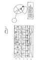
- Figure 1 shows examples of measurements from animal tests, more precisely results from measurements on a sheep.
- Curve a shows an impedance signal measured with a standard bipolar pacing lead positioned in right ventricular apex as indicated in the figure.
- Curves b and c show the right ventricular pressure and the left ventricular pressure respectively.
- Curve d is the surface ECG and curve e shows the respiratory flow.
- a distinct notch is seen in the intracardiac impedance, marked by a circle in curve a, is seen in the majority of measurements. Its location is closely after the point where the ventricular pressure curves b and c are down to a minimum and prior to atrial systole, i.e.
- the notches are located in early heart diastole. In some measurements the notch occurs at the time of atrial systole which could lead to the conclusion that it is caused by atrial contraction. However, the notch is present even if no atrial activity is observed, i.e. even when no P-wave is available.
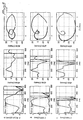
- the impedance measured in human beings also exhibits a notch, marked by circles in figure 2, cf. also the above-mentioned document by Brian R. Pickett et. al.
- the diagrams a in figure 2 show the bipolar right ventricular impedance measured in humans with no prior history of coronary artery decease for three different tip-ring distances, viz 10, 20 and 30 mm respectively.
- Corresponding intracardiac ECGs are shown at b in the figure.
- the measurements shown in figure 2 are made during rest conditions with the patient lying down, and the curves shown are calculated from measurements during 10 or more heartbeats.
- Figure 3 shows another example of such bipolar right ventricular impedance measurements on a human being during rest conditions and drug-induced workload together with corresponding ECGs. Also in this case the curves shown are averaged curves of both the intracardiac electrogram and the impedance calculated from 10 or more heartbeats. A distinct notch in diastolic impedance is seen in all examples, marked by circles in the figure. Although the over-all impedance might show a slight change in morphology, little or no change in notch appearance between rest and load conditions is observed, the timing of the notch being earlier during load. Thus for a healthy patient the shape of the notch does not change significantly with the load, whereas the situation might be different for patients with cardiac abnormalities that alter the relaxation patterns.
- Figure 4 shows the right ventricular bipolar impedance i), the first time derivative of the impedance ii), and a corresponding loop plot iii) of these two signals. As appears there is very little variation in the impedance notch appearance.
- the three set of diagrams i, ii and iii, represent three different tip-ring distances, viz. 10mm, 20mm and 30 mm respectively.
- the unipolar impedance i.e. the impedance measured between an electrode tip positioned in the ventricular apex and the casing of the implanted monitor is shown together with the corresponding time derivative of this impedance signal and the loop plot for a healthy patient in rest, curve a, for a load of 30 W, curve b, and a load of 75 W, curve c. Also in this case the occurrence of the notch in the impedance signal is evident.
- FIG. 6 shows results from corresponding measurements on a patient with dilated cardiomyopathy.
- the curves a), b) and c) show the result from right ventricular unipolar impedance measurements in a patient during rest, curve a, a load of 30 W (cycling), curve b and a load of 60 W (cycling), curve c.
- the impedance signal Z, the first time derivative of the impedance dZ/dt and a loop plotted of these two signals dZ/dt and Z are shown.
- the changes in the notch appearance are emphasized in the loop plots.
- Animal tests comprising impedance measurements performed simultaneously with echocardiographic measurements of mitral blood flow also show the appearance of an impedance notch at the time for maximum inflow in early diastole, and prior to the ventricular filling caused by atrial contraction. It has also appeared that the time between ECG R-wave and the occurrence of an impedance notch correlate well with the heart rate in a physiological manner.
- the purpose of the present invention is to utilize the above discussed knowledge to provide a notch monitoring diagnostics for detecting early signs of disturbed relaxation patterns of the heart.
- any change, other than normal notch variations, in the parameter considered indicates a relaxation disturbance.
- Said parameter is compared to a template defining normal notch variations, i.e. timing and shape, during for example rest and workload, upright and supine position etc.
- An example of such normal changes in notch characteristics is a reduced time interval between R-wave, or ventricular stimulation, and detected notch with increased heart rate, as discussed above.
- the loop is superior to e.g. signal-to-time representation since it does not only take the signal of interest into account, but also one additional quantity is analysed. Small changes in the measured signal are revealed in this way in much greater detail.
- the template must be determined for each individual patient under the supervision of a physician.
- the monitoring possibility of early signs of disturbed relaxation patterns obtained by the present invention give a very important diagnostic advantage and make it possible for the physician to take suitable actions that would prevent a congestive heart failure to escalate and perhaps even prevent the patient from hospitalization.
- said monitor comprises means to supervise the patient's heart rate
- said comparator is adapted to determine the correlation between the time between the apperance of an R-wave/ventricular stimulation and the time of the notch occurrence, and the heart rate.
- the detecting means is preferably adapted to detect the timing of occurred notches by measuring the time between the appearance of R-wave or, where appropriate, the delivery of a ventricular stimulation pulse, and subsequent occurrence of a notch in the impedance signal.
- the time interval between sensed R-wave or ventricular stimulation event, and detected notch is measured and can be stored together with actual heart rate to make it possible for the physician to follow notch behavioural statistics in terms of date and time for notch change, number of notch change events, frequency change and longevity, level of notch change etc. for then deciding whether to make additional medical check-ups.
- said comparator is adapted to compare the shape of the loop in that part of the loop which corresponds to the notch portion of the impedance signal with corresponding part of the loop template. Certain phenomena appearing in the impedance signal can be emphasized in the loop plot, thus facilitating detection and analysis of these phenomena.
- said comparator is adapted to compare notch timing and shape, notch time derivatives and corresponding loop characteristics with corresponding predetermined timing and shape, time derivative and loop templates respectively.
- a first averaging means is connected to said impedance measuring means for determining an average impedance signal of impedance signals measured during a predetermined number of cardiac cycles and said detecting means is connected to said first averaging means to detect the occurrence of and said parameter of said at least one notch from said average impedance signal.
- the notch may, however, appear somewhat unclear and not distinct in the average impedance signal.
- the notch may in these cases appear more clearly in the standard deviation curve obtained from the measured impedance curves. Therefore, according to another advantageous embodiment of the monitor according to the invention said first averaging means is adapted to determine the standard deviation of impedance signals measured during a predetermined number of cardiac cycles and said detecting means is connected to said first averaging means to detect the occurrence of and said parameter of said at least one notch from said standard deviation.
- the invention also relates to a heart stimulator comprising a pulse generator for generating stimulation pulses for delivery to a patient's heart by means of electrode means adapted for location in one or both of the lower chambers of the heart, which is characterized by a monitor according to the invention.
- the invention also relates to a method of monitoring diastolic relaxation of a patient's heart according to the introductory portion of the description, which is characterized by the steps of forming the time derivative of the impedance signal, plotting impedance values against related time derivative values to form a loop for each cardiac cycle, and comparing said loop with a predetermined loop template.
- an impedance signal can be used which is obtained by means of electrode means located in one or both of the lower chambers of the heart or in coronary sinus.
- figure 1 shows measurement signals obtained from an animal test
- figures 2 and 3 show the impedance signal and intercardiac ECG obtained from a human being during rest condition and during drug-induced workload
- figure 4 shows the impedance signal, the time derivated impedance signal and corresponding loops formed by impedance values and corresponding time derivatived values from right ventricular bipolar impedance measurements in a healthy patient during rest for three different interelectrode distances
- figure 5 shows an unipolar impedance signal obtained from a healthy patient for rest condition and two different load conditions together with corresponding time derivatives and loops
- figure 6 shows the corresponding curves for a cardiomyopathy patient
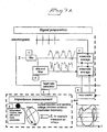
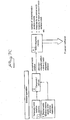
- figure 7 shows in the form of a blockdiagram an embodiment of the monitor according to the invention
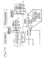
- figure 8 illustrates an example of obtaining information about notch pattern variation
- figure 9 shows the R-wave-notch time and the standard derivation of the notch loop area
- the blockdiagram in figure 7 is divided into a signal preparation part, a notch detection part, a notch characteristics part, an impedance measurement part, and a final general operation part.
- the letter Z denotes the measured impedance, as will be further explained below, and in the signal preparation part the impedance signal Z is supplied to a filter 1, which is a smoothing filter for the raw impedance signal in order to remove noise and artefacts.
- the time derivative and filter unit 2 is a high pass filter to create a first time derivate of the impedance signal and a smoothing filter to remove noise and artefacts
- An electrogram is also recorded for the patient and supplied to a heart rate calculator 3.
- the heart rate calculator calculates the heart rate from sensed R-waves, or where appropriate, ventricular stimulations.
- An ensemble average unit 4 is provided to calculate an average impedance signal from e.g. ten cardiac cycles, as measured from the electrogram.
- the ensemble average unit 4 is adapted to also calculate a corresponding averaged time derivative.
- a loop creator 5 is connected to the ensemble average unit 4 to receive the average impedance signal and the average time derivative and form a loop for the cardiac cycle by plotting impedance values against related time derivative values. From the loop together with timing inputs from a notch detector 6 notch characteristics are determined.
- the notch detector 6 of the notch detection part is connected to the ensemble average unit 4 to detect the existence of notches from the average impedance signal and, if so, the timing in the cardiac cycle of the notch.
- the notch detector 6 is adapted to determine, as an alternative, the existence of a notch from the average time derivative received from the ensemble average unit 4.
- notch characteristics for example notch shapes as seen in either impedance signal, first time derivative of the impedance signal or in the corresponding loop, R-wave to notch time correlated to heart rate, etc. are continuously stored.
- the normal notch 8 variation memory contains normal notch variation pattern templates for the characteristics stored in memory 7. These templates are unique for each patient and are individually determined under the supervision of a physician.
- the impedance measurement part illustrates the impedance measurements performed by the monitor according to the invention or by a heart stimulator, like a pacemaker, provided with such a monitor.
- the monitor or heart stimulator comprises a lead with one or more electrodes, in the example a bipolar ventricular electrode is shown. Current is supplied through the lead and the corresponding voltage between the two electrodes or between one electrode and the monitor or stimulator casing is measured. This voltage represents the impedance Z.
- the final general operation part of the monitor includes a comparator and detector 10 for continuos comparison of actual notch variation pattern, received from the memory 7, with a template, received from the memory 8.
- a comparator and detector 10 for continuos comparison of actual notch variation pattern, received from the memory 7, with a template, received from the memory 8.
- Notch pattern variations including any detection of abnormal notch variation patterns are stored in the notch diagnostic memory 11.
- the number of abnormal notch variation events, time and date for abnormal notches, longevity of each abnormal notch variation event, level of notch changes etc. can be stored. The physician can then use this information to follow notch behavioural statistics to decide whether to make additional medical check-ups.
- Figure 8 illustrates an example of obtaining information about notch pattern variations.
- a dZ/dt-Z loop from one heartbeat is shown, and at 14 the corresponding notch loop area is shown.
- notch loop areas from a plurality of heartbeats are shown. As appears the loop areas obtained from different heartbeats vary and the standard deviation value STD of the notch loop areas reveals the variation pattern at this particular heart rate.
- Figure 9 shows an example of measured normalized R-wave-notch time plotted against heart rate (bpm). This is what it might look like in one single patient. Along with the measured temporal information, a schematic curve of standard deviation STD of the notch loop area is plotted against the heart rate. Together these curves form one example of notch variation pattern that can be calculated and then stored in the temporary notch variation memory 7 in figure 7 and compared to a normal notch variation pattern stored in the memory 8 in figure 7.
Description
Claims (12)
- A monitor for monitoring diastolic relaxation of at least one ventricle of a patient's heart, comprising an impedance measurement means (9) including electrode means for measuring an impedance and generating a corresponding impedance signal (7), a detecting means (6) connected to said impedance measurement means for detecting the occurrence of at least one notch in said impedance signal coincident with the entry of blood into at least one ventricle of the heart and for detecting at least one parameter of said at least one notch, said detecting means comprising a differentiating means (2) to form the time derivative of said impedance signal, and a loop creator (5) connected to said impedance measurement means (9) and to said differentiating means (2) to receive said impedance signal and said time derivative of the impedance signal for plotting impedance values against related time derivative values to form a loop for each cardiac cycle, characterized in that a comparator (10) is connected to said loop creator (5) for comparing said loop with a predetermined loop template defining normal notch variations in regard of timing and shape to determine a change from said normal notch variations.
- The monitor according to claim 1, said monitor comprising means to supervise the patient's heart rate, characterized in that said comparator (10) is adapted to determine the correlation between the time between the appearance of an R-wave/ventricular stimulation and the time of the notch occurrence, and the heart rate.
- The monitor according to any one of the preceding claims, characterized in that said comparator is adapted to compare notch timing and shape, notch time derivatives and corresponding loop characteristics with corresponding predetermined timing and shape, time derivative and loop templates respectively.
- The monitor according to any one of the preceding claims, characterized in that a first averaging means is connected to said impedance measuring means (9) for determining an average impedance signal of impedance signals measured during a predetermined number of cardiac cycles, and in that said detecting means (6) is connected to said first averaging means to detect the occurrence of and said parameter of said at least one notch from said average impedance signal.
- The monitor according to claim 4, characterized in that said first averaging means is adapted to determine the standard deviation of impedance signals measured during a predetermined number of cardiac cycles and in that said detecting means (6) is connected to said first averaging means to detect the occurrence of and said parameter of said at least one notch from said standard deviation.
- The monitor according to any one of the preceding claims, characterized in that a second averaging means is connected to said differentiating means (2) for determining an average time derivative of time derivatives of impedance signals measured during a predetermined number of cardiac cycles and in said detecting means (6) is connected to said second averaging means to detect the occurrence of and said parameter of said at least one notch from said average time derivative.
- The monitor according to claim 6, characterized in that said second averaging means is adapted to determine the standard deviation of time derivatives of impedance signals measured during said predetermined number of cardiac cycles and in that said detecting means (6) is connected to said second averaging means to detect the occurrence of and said parameter of said at least one notch from said standard deviation.
- The monitor according to any one of the preceding claims, characterized in that said loop creator (5) is connected to said first and second averaging means to receive said average impedance signal and its corresponding average time derivative to form a corresponding average loop and in that said comparator (10) is adapted to compare said average loop with said predetermined loop template.
- The monitor according to any one of the claims 4-8, characterized in that said first and second averaging means are realised by one and the same averaging means (4).
- The monitor according to any one of the preceding claims, characterized in that said electrode means comprises a bipolar ventricular electrode and in that said impedance measuring means (9) is adapted to measure the impedance between electrode tip and ring.
- The monitor according to any one of the claims 1 - 9, characterized in that said electrode means comprises an unipolar ventricular electrode and in that said impedance measuring means (9) is adapted to measure the impedance between electrode and monitor casing.
- A heart stimulator comprising a pulse generator for generating stimulation pulses for delivery to a patient's heart by means of electrode means adapted for location in one or both of the lower chambers of the heart, characterized by a monitor according to any one of the preceding claims.
Applications Claiming Priority (3)
| Application Number | Priority Date | Filing Date | Title |
|---|---|---|---|
| SE0004417A SE0004417D0 (en) | 2000-11-28 | 2000-11-28 | Implantable device |
| SE0004417 | 2000-11-28 | ||
| PCT/SE2001/002615 WO2002043587A1 (en) | 2000-11-28 | 2001-11-26 | A monitor and a method for monitoring diastolic relaxation using impedance measurement |
Publications (2)
| Publication Number | Publication Date |
|---|---|
| EP1339320A1 EP1339320A1 (en) | 2003-09-03 |
| EP1339320B1 true EP1339320B1 (en) | 2005-11-02 |
Family
ID=20282043
Family Applications (1)
| Application Number | Title | Priority Date | Filing Date |
|---|---|---|---|
| EP01998265A Expired - Lifetime EP1339320B1 (en) | 2000-11-28 | 2001-11-26 | A monitor for monitoring diastolic relaxation using impedance measurement |
Country Status (5)
| Country | Link |
|---|---|
| US (1) | US7082329B2 (en) |
| EP (1) | EP1339320B1 (en) |
| DE (1) | DE60114658T2 (en) |
| SE (1) | SE0004417D0 (en) |
| WO (1) | WO2002043587A1 (en) |
Families Citing this family (29)
| Publication number | Priority date | Publication date | Assignee | Title |
|---|---|---|---|---|
| US7127289B2 (en) * | 2001-12-05 | 2006-10-24 | Cardiac Pacemakers, Inc. | Cardiac resynchronization system employing mechanical measurement of cardiac walls |
| US20060177852A1 (en) * | 2001-12-12 | 2006-08-10 | Do-Coop Technologies Ltd. | Solid-fluid composition |
| SE0200921D0 (en) * | 2002-03-25 | 2002-03-25 | St Jude Medical | A heart monitoring device, a system including such a device and a lesser use of the system |
| SE0202290D0 (en) * | 2002-07-22 | 2002-07-22 | St Jude Medical | Monitor |
| WO2005107582A1 (en) * | 2004-05-06 | 2005-11-17 | St. Jude Medical Ab | Detection of diastolic heart failure |
| US7578793B2 (en) * | 2004-11-22 | 2009-08-25 | Widemed Ltd. | Sleep staging based on cardio-respiratory signals |
| DE102005012386B4 (en) | 2005-03-17 | 2010-01-28 | Siemens Ag | A method of predicting the location of the diastolic resting phase in the cardiac cycle and using the method of displaying the coronary arteries |
| US7630763B2 (en) | 2005-04-20 | 2009-12-08 | Cardiac Pacemakers, Inc. | Thoracic or intracardiac impedance detection with automatic vector selection |
| US20060271121A1 (en) * | 2005-05-25 | 2006-11-30 | Cardiac Pacemakers, Inc. | Closed loop impedance-based cardiac resynchronization therapy systems, devices, and methods |
| US9839781B2 (en) | 2005-08-22 | 2017-12-12 | Cardiac Pacemakers, Inc. | Intracardiac impedance and its applications |
| US8494618B2 (en) * | 2005-08-22 | 2013-07-23 | Cardiac Pacemakers, Inc. | Intracardiac impedance and its applications |
| US7974691B2 (en) * | 2005-09-21 | 2011-07-05 | Cardiac Pacemakers, Inc. | Method and apparatus for controlling cardiac resynchronization therapy using cardiac impedance |
| EP1981986A2 (en) * | 2006-01-04 | 2008-10-22 | Do-Coop Technologies Ltd | Cryoprotective compositions and methods of using same |
| US20090253613A1 (en) * | 2006-01-04 | 2009-10-08 | Do-Coop Technologies Ltd. | Solid-Fluid Composition |
| US20090004296A1 (en) * | 2006-01-04 | 2009-01-01 | Do-Coop Technologies Ltd. | Antiseptic Compositions and Methods of Using Same |
| US8712519B1 (en) * | 2006-03-31 | 2014-04-29 | Pacesetter, Inc. | Closed-loop adaptive adjustment of pacing therapy based on cardiogenic impedance signals detected by an implantable medical device |
| US20080027350A1 (en) * | 2006-07-13 | 2008-01-31 | Advanced Cardiovascular Systems, Inc. | Methods and apparatus for localization, diagnosis, contact or activity detection of bio-electric tissue |
| US7402183B1 (en) | 2006-07-19 | 2008-07-22 | Pacesetter, Inc. | High capacitance cathode foil produced by abrasion process using titanium nitride powder |
| US7751888B1 (en) * | 2006-08-28 | 2010-07-06 | Pacesetter, Inc. | Systems and methods for delivering stimulation pulses using an implantable cardiac stimulation device |
| EP2059299B1 (en) * | 2006-08-28 | 2017-07-26 | St. Jude Medical AB | Determining the variation over the time of a medical parameter of a human being |
| US8364263B2 (en) | 2006-10-26 | 2013-01-29 | Cardiac Pacemakers, Inc. | System and method for systolic interval analysis |
| WO2008105691A1 (en) * | 2007-02-28 | 2008-09-04 | St. Jude Medical Ab | Device and method for detecting a myocardial infarction and treating the myocardial infarction using therapeutic light |
| US20080300500A1 (en) * | 2007-05-30 | 2008-12-04 | Widemed Ltd. | Apnea detection using a capnograph |
| US8868165B1 (en) | 2007-09-28 | 2014-10-21 | Pacesetter, Inc. | Use of cardiogenic impedance waveform morphology to analyze cardiac conditions and to adjust treatment therapy |
| EP2224849B1 (en) * | 2007-12-21 | 2014-07-23 | St. Jude Medical AB | Device for monitoring acute decompensated heart failure |
| EP2240241B1 (en) | 2008-01-28 | 2014-04-30 | St. Jude Medical AB | Implantable heart stimulator for measuring dyssynchrony using impedance |
| US8498702B2 (en) | 2008-12-22 | 2013-07-30 | St. Jude Medical Ab | Implantable medical device and method for monitoring synchronicity of the ventricles of a heart |
| EP3285857B1 (en) * | 2015-04-20 | 2024-02-14 | Medtronic, Inc. | Method and medical device for discriminating between a supraventricular tachycardia and a ventricular tachycardia |
| CN109011152B (en) * | 2018-08-22 | 2022-03-18 | 创领心律管理医疗器械(上海)有限公司 | Fixing device, testing device and testing method for pacemaker in-vitro test |
Family Cites Families (7)
| Publication number | Priority date | Publication date | Assignee | Title |
|---|---|---|---|---|
| US4095705A (en) * | 1977-02-02 | 1978-06-20 | Hood Clifton E | Agricultural airplane loading device |
| US4905696A (en) | 1987-10-07 | 1990-03-06 | Siemens Aktiengesellschaft | Method and apparatus for P-synchronously stimulating the heart of a patient |
| US5211177A (en) * | 1990-12-28 | 1993-05-18 | Regents Of The University Of Minnesota | Vascular impedance measurement instrument |
| US5235976A (en) * | 1991-12-13 | 1993-08-17 | Cardiac Pacemakers, Inc. | Method and apparatus for managing and monitoring cardiac rhythm using active time as the controlling parameter |
| SE9203822D0 (en) * | 1992-12-18 | 1992-12-18 | Siemens Elema Ab | DEVICE TO ANALYZE THE FUNCTION OF A HEART |
| FR2707860B1 (en) * | 1993-07-23 | 1995-09-08 | Bour Jean | Apparatus for measuring and processing physiological signals and automatic method implemented by said apparatus. |
| SE9304029D0 (en) | 1993-12-03 | 1993-12-03 | Siemens Elema Ab | Analyzer for analyzing electrical signals from a heart |
-
2000
- 2000-11-28 SE SE0004417A patent/SE0004417D0/en unknown
-
2001
- 2001-11-26 DE DE60114658T patent/DE60114658T2/en not_active Expired - Lifetime
- 2001-11-26 WO PCT/SE2001/002615 patent/WO2002043587A1/en active IP Right Grant
- 2001-11-26 US US10/432,970 patent/US7082329B2/en not_active Expired - Fee Related
- 2001-11-26 EP EP01998265A patent/EP1339320B1/en not_active Expired - Lifetime
Also Published As
| Publication number | Publication date |
|---|---|
| WO2002043587A1 (en) | 2002-06-06 |
| DE60114658T2 (en) | 2006-07-20 |
| US20040049238A1 (en) | 2004-03-11 |
| US7082329B2 (en) | 2006-07-25 |
| DE60114658D1 (en) | 2005-12-08 |
| EP1339320A1 (en) | 2003-09-03 |
| SE0004417D0 (en) | 2000-11-28 |
Similar Documents
| Publication | Publication Date | Title |
|---|---|---|
| EP1339320B1 (en) | A monitor for monitoring diastolic relaxation using impedance measurement | |
| JP5103482B2 (en) | Heart attack detector | |
| US7894889B2 (en) | ECG signal power vector detection of ischemia or infarction | |
| US6589188B1 (en) | Method for monitoring heart failure via respiratory patterns | |
| US5427112A (en) | Device for analyzing the function of a heart | |
| US7653431B2 (en) | Arrhythmia discrimination based on determination of rate dependency | |
| US6021350A (en) | Implantable heart stimulator with a maximum stimulation rate that is adjusted dependent on ischemia detection | |
| US20080300641A1 (en) | Cardiac information and activity information association systems, apparatus, and methods | |
| CN106456023B (en) | Method and apparatus for detecting atrial tachyarrhythmia using heart sounds | |
| US9180300B2 (en) | Left-ventricular pacing site selection guided by electrogram morphology analysis | |
| WO1999039636A1 (en) | Non-invasive cardiorespiratory monitor with synchronized bioimpedance sensing | |
| US8457728B2 (en) | Automatic detection of premature ventricular complexes for heart rate turbulence measurements | |
| US9167980B2 (en) | Detection and monitoring using high frequency electrogram analysis | |
| US20200170526A1 (en) | Detection and monitoring using high frequency electrogram analysis | |
| JPH0698864A (en) | Screening method for myocardinal ischemia patient | |
| Fröhlig et al. | Atrial sensing performance of AV universal pacemakers during exercise | |
| US9254094B2 (en) | Detection and monitoring using high frequency electrogram analysis | |
| US6923772B2 (en) | Apparatus and method for determining responders to cardiac resynchronization therapy using implantable accelerometers | |
| US20040148109A1 (en) | Method and apparatus for prediction of cardiac dysfunction | |
| US7917194B1 (en) | Method and apparatus for detecting pulmonary edema | |
| US20140257070A1 (en) | Processing of lap signals | |
| EP2954841A1 (en) | Detection and monitoring using high frequency electrogram analysis | |
| Theorell et al. | Non‐Invasive Methods for Evaluating the Importance of Heart Rate and Atrial Activity in Cardiac Pacing: Results of Ballistocardiography and Digital Plethysmography Studies in Six Patients with Heart Block |
Legal Events
| Date | Code | Title | Description |
|---|---|---|---|
| PUAI | Public reference made under article 153(3) epc to a published international application that has entered the european phase |
Free format text: ORIGINAL CODE: 0009012 |
|
| 17P | Request for examination filed |
Effective date: 20030630 |
|
| AK | Designated contracting states |
Kind code of ref document: A1 Designated state(s): AT BE CH CY DE DK ES FI FR GB GR IE IT LI LU MC NL PT SE TR |
|
| RIN1 | Information on inventor provided before grant (corrected) |
Inventor name: JAERVERUD, KARIN |
|
| RBV | Designated contracting states (corrected) |
Designated state(s): CH DE FR IE IT LI |
|
| 17Q | First examination report despatched |
Effective date: 20040528 |
|
| GRAP | Despatch of communication of intention to grant a patent |
Free format text: ORIGINAL CODE: EPIDOSNIGR1 |
|
| RTI1 | Title (correction) |
Free format text: A MONITOR FOR MONITORING DIASTOLIC RELAXATION USING IMPEDANCE MEASUREMENT |
|
| GRAS | Grant fee paid |
Free format text: ORIGINAL CODE: EPIDOSNIGR3 |
|
| GRAA | (expected) grant |
Free format text: ORIGINAL CODE: 0009210 |
|
| AK | Designated contracting states |
Kind code of ref document: B1 Designated state(s): CH DE FR IE IT LI |
|
| PG25 | Lapsed in a contracting state [announced via postgrant information from national office to epo] |
Ref country code: IT Free format text: LAPSE BECAUSE OF FAILURE TO SUBMIT A TRANSLATION OF THE DESCRIPTION OR TO PAY THE FEE WITHIN THE PRESCRIBED TIME-LIMIT;WARNING: LAPSES OF ITALIAN PATENTS WITH EFFECTIVE DATE BEFORE 2007 MAY HAVE OCCURRED AT ANY TIME BEFORE 2007. THE CORRECT EFFECTIVE DATE MAY BE DIFFERENT FROM THE ONE RECORDED. Effective date: 20051102 |
|
| REG | Reference to a national code |
Ref country code: CH Ref legal event code: EP Ref country code: CH Ref legal event code: NV Representative=s name: E. BLUM & CO. PATENTANWAELTE |
|
| REF | Corresponds to: |
Ref document number: 60114658 Country of ref document: DE Date of ref document: 20051208 Kind code of ref document: P |
|
| PLBE | No opposition filed within time limit |
Free format text: ORIGINAL CODE: 0009261 |
|
| STAA | Information on the status of an ep patent application or granted ep patent |
Free format text: STATUS: NO OPPOSITION FILED WITHIN TIME LIMIT |
|
| 26N | No opposition filed |
Effective date: 20060803 |
|
| EN | Fr: translation not filed | ||
| PG25 | Lapsed in a contracting state [announced via postgrant information from national office to epo] |
Ref country code: FR Free format text: LAPSE BECAUSE OF FAILURE TO SUBMIT A TRANSLATION OF THE DESCRIPTION OR TO PAY THE FEE WITHIN THE PRESCRIBED TIME-LIMIT Effective date: 20061222 |
|
| REG | Reference to a national code |
Ref country code: CH Ref legal event code: PFA Owner name: ST. JUDE MEDICAL AB Free format text: ST. JUDE MEDICAL AB# #175 84 JAERFAELLA (SE) -TRANSFER TO- ST. JUDE MEDICAL AB# #175 84 JAERFAELLA (SE) |
|
| PG25 | Lapsed in a contracting state [announced via postgrant information from national office to epo] |
Ref country code: FR Free format text: LAPSE BECAUSE OF FAILURE TO SUBMIT A TRANSLATION OF THE DESCRIPTION OR TO PAY THE FEE WITHIN THE PRESCRIBED TIME-LIMIT Effective date: 20051130 |
|
| PG25 | Lapsed in a contracting state [announced via postgrant information from national office to epo] |
Ref country code: FR Free format text: LAPSE BECAUSE OF FAILURE TO SUBMIT A TRANSLATION OF THE DESCRIPTION OR TO PAY THE FEE WITHIN THE PRESCRIBED TIME-LIMIT Effective date: 20051102 |
|
| PGFP | Annual fee paid to national office [announced via postgrant information from national office to epo] |
Ref country code: IE Payment date: 20081114 Year of fee payment: 8 |
|
| REG | Reference to a national code |
Ref country code: IE Ref legal event code: MM4A |
|
| PG25 | Lapsed in a contracting state [announced via postgrant information from national office to epo] |
Ref country code: IE Free format text: LAPSE BECAUSE OF NON-PAYMENT OF DUE FEES Effective date: 20091126 |
|
| PGFP | Annual fee paid to national office [announced via postgrant information from national office to epo] |
Ref country code: CH Payment date: 20121126 Year of fee payment: 12 |
|
| REG | Reference to a national code |
Ref country code: CH Ref legal event code: PL |
|
| PG25 | Lapsed in a contracting state [announced via postgrant information from national office to epo] |
Ref country code: LI Free format text: LAPSE BECAUSE OF NON-PAYMENT OF DUE FEES Effective date: 20131130 Ref country code: CH Free format text: LAPSE BECAUSE OF NON-PAYMENT OF DUE FEES Effective date: 20131130 |
|
| PGFP | Annual fee paid to national office [announced via postgrant information from national office to epo] |
Ref country code: DE Payment date: 20141128 Year of fee payment: 14 |
|
| REG | Reference to a national code |
Ref country code: DE Ref legal event code: R119 Ref document number: 60114658 Country of ref document: DE |
|
| PG25 | Lapsed in a contracting state [announced via postgrant information from national office to epo] |
Ref country code: DE Free format text: LAPSE BECAUSE OF NON-PAYMENT OF DUE FEES Effective date: 20160601 |