EP1350906B1 - Building component - Google Patents
Building component Download PDFInfo
- Publication number
- EP1350906B1 EP1350906B1 EP03251982A EP03251982A EP1350906B1 EP 1350906 B1 EP1350906 B1 EP 1350906B1 EP 03251982 A EP03251982 A EP 03251982A EP 03251982 A EP03251982 A EP 03251982A EP 1350906 B1 EP1350906 B1 EP 1350906B1
- Authority
- EP
- European Patent Office
- Prior art keywords
- cushion
- frame
- building component
- release mechanism
- bead
- Prior art date
- Legal status (The legal status is an assumption and is not a legal conclusion. Google has not performed a legal analysis and makes no representation as to the accuracy of the status listed.)
- Expired - Lifetime
Links
Images

Classifications
-
- E—FIXED CONSTRUCTIONS
- E04—BUILDING
- E04H—BUILDINGS OR LIKE STRUCTURES FOR PARTICULAR PURPOSES; SWIMMING OR SPLASH BATHS OR POOLS; MASTS; FENCING; TENTS OR CANOPIES, IN GENERAL
- E04H15/00—Tents or canopies, in general
- E04H15/20—Tents or canopies, in general inflatable, e.g. shaped, strengthened or supported by fluid pressure
-
- E—FIXED CONSTRUCTIONS
- E04—BUILDING
- E04H—BUILDINGS OR LIKE STRUCTURES FOR PARTICULAR PURPOSES; SWIMMING OR SPLASH BATHS OR POOLS; MASTS; FENCING; TENTS OR CANOPIES, IN GENERAL
- E04H15/00—Tents or canopies, in general
- E04H15/32—Parts, components, construction details, accessories, interior equipment, specially adapted for tents, e.g. guy-line equipment, skirts, thresholds
- E04H15/64—Tent or canopy cover fastenings
- E04H15/642—Tent or canopy cover fastenings with covers held by elongated fixing members locking in longitudinal recesses of a frame
- E04H15/644—Tent or canopy cover fastenings with covers held by elongated fixing members locking in longitudinal recesses of a frame the fixing members being a beading
-
- E—FIXED CONSTRUCTIONS
- E04—BUILDING
- E04H—BUILDINGS OR LIKE STRUCTURES FOR PARTICULAR PURPOSES; SWIMMING OR SPLASH BATHS OR POOLS; MASTS; FENCING; TENTS OR CANOPIES, IN GENERAL
- E04H15/00—Tents or canopies, in general
- E04H15/32—Parts, components, construction details, accessories, interior equipment, specially adapted for tents, e.g. guy-line equipment, skirts, thresholds
- E04H15/64—Tent or canopy cover fastenings
- E04H15/642—Tent or canopy cover fastenings with covers held by elongated fixing members locking in longitudinal recesses of a frame
- E04H15/648—Tent or canopy cover fastenings with covers held by elongated fixing members locking in longitudinal recesses of a frame the longitudinal recesses being made from two clamping members
-
- E—FIXED CONSTRUCTIONS
- E04—BUILDING
- E04H—BUILDINGS OR LIKE STRUCTURES FOR PARTICULAR PURPOSES; SWIMMING OR SPLASH BATHS OR POOLS; MASTS; FENCING; TENTS OR CANOPIES, IN GENERAL
- E04H15/00—Tents or canopies, in general
- E04H15/20—Tents or canopies, in general inflatable, e.g. shaped, strengthened or supported by fluid pressure
- E04H2015/202—Tents or canopies, in general inflatable, e.g. shaped, strengthened or supported by fluid pressure with inflatable panels, without inflatable tubular framework
- E04H2015/203—Tents or canopies, in general inflatable, e.g. shaped, strengthened or supported by fluid pressure with inflatable panels, without inflatable tubular framework supported by a non-inflatable structure or framework
-
- E—FIXED CONSTRUCTIONS
- E04—BUILDING
- E04H—BUILDINGS OR LIKE STRUCTURES FOR PARTICULAR PURPOSES; SWIMMING OR SPLASH BATHS OR POOLS; MASTS; FENCING; TENTS OR CANOPIES, IN GENERAL
- E04H15/00—Tents or canopies, in general
- E04H15/20—Tents or canopies, in general inflatable, e.g. shaped, strengthened or supported by fluid pressure
- E04H2015/202—Tents or canopies, in general inflatable, e.g. shaped, strengthened or supported by fluid pressure with inflatable panels, without inflatable tubular framework
- E04H2015/205—Tents or canopies, in general inflatable, e.g. shaped, strengthened or supported by fluid pressure with inflatable panels, without inflatable tubular framework made from two sheets with intermediate spacer means
Definitions
- the present invention relates to building components, particularly, but not exclusively, for roofing, in the form of inflatable cushions.
- the cushions comprise two or more layers of a plastic foil material such as ETFE (ethylene tetra flouro ethylene) inflated with low pressure air.
- ETFE ethylene tetra flouro ethylene
- the ETFE foil cushion is restrained in a perimeter frame usually manufactured from extruded aluminium, which in turn is fixed to a support structure. As the ETFE foil cushion is inflated, the ETFE is put under tension and forms a tight drum like skin.
- ETFE foil cushions are sold under a number of trade names, for example Texlon.
- ETFE cushions of this kind are fixed to a support structure to form a cladding and are used to enclose atria or other enclosed spaces to provide a transparent or translucent roof or façade to the enclosure, as an alternative to and in a similar way to glass.
- a number of buildings have been built using this technology most notably the Eden project in Cornwall, England.
- the smoke, and/or fumes can be extracted by a mechanical extraction system usually consisting of fire-rated duct work and extraction fans.
- the smoke and/or fumes can be extracted by opening part of the roof or building façade and allowing the smoke to ventilate to atmosphere through the action of convection and/or wind.
- ETFE foil cushions can be used to ventilate smoke and/or fumes to the atmosphere in much the same ways as other cladding systems in that they can be fixed to a frame which opens automatically through a mechanical device in the event of fire.
- ETFE is a thermo-plastic material and therefore has the innate property of failing if the temperature reaches approximately 200°C, as the material loses its tensile properties as its temperature increases. When the cushion fails, it allows smoke and/or fumes to ventilate naturally to the atmosphere.
- the above methods suffer from a number of draw backs.
- the mechanical extraction approach is expensive and requires fire-rated machinery, regular maintenance and testing.
- Natural extraction requires expensive opening frames, which are complex to render, weather and watertight. They do not look the same as the adjacent cladding as they require a secondary opening frame, and mechanical operating parts which themselves require regular maintenance and testing.
- the failure of the ETFE due to high temperature does not occur if the building fire is located some way away from the ETFE, as the ETFE is not sufficiently heated by smoke and/or fumes to fail.
- US-A-4 878 322 describes a building component with all of the features of the preamble of claim 1, in that it discloses a skeletal frame supporting a continuous sealed, flattened plastic film tube for retaining gas under positive pressure, whereby the tube has opposed edges with a flexible film retainer line passing therethrough to form edge beads.
- the present invention provides a building component in the form of an inflatable cushion comprising two or more sheets of plastics foil attached by connecting means to a relatively rigid frame surrounding and supporting the foil sheets, the building component further incorporating a release mechanism in or adjacent to the frame arranged to release the foil sheets from the frame.
- the sheets are made from ethylene tetrafluoro ethylene (ETFE).
- EFE ethylene tetrafluoro ethylene
- the sheets define a space between them which is inflated with air and the frame restrains the sheets about their perimeters, thereby forming the cushion.
- the release mechanism may extend the entire periphery of the cushion. Alternatively, it may extend only part of the way around, for example, in the case of a polygonal cushion, it may extend around all sides except one. In the case of a rectangular cushion, therefore, it might extend around three sides.
- the cushion has a bead formed around its periphery, and the bead is located within the frame.
- the bead may be a rope encapsulated by the sheet material.
- the bead may be held by a keder edge within the frame.
- the frame may be manufactured from extruded aluminium which in turn may be fixed to a support structure.
- the frame incorporates a device which releases the ETFE foil cushion from the frame in the event of fire so allowing the smoke to ventilate to atmosphere.
- the release mechanism comprises a device which removes the rope from the bead on demand, releasing the ETFE foil cushion from the frame.
- Suitable means for removing the rope include by a mechanical winch, or ram, block and tackle. This can be done via a turning wheel.
- the release mechanism may comprise a hinged member engaging the cushion, the hinged member being movable on demand to a position in which it does not engage the cushion, thereby releasing the cushion from the frame.
- the frame incorporates a cutting device which either physically cuts or melts the ETFE foil along the edge of the cushion.
- the release mechanism comprises an electrical resistance cable which causes the edge of the cushion to melt on demand, releasing the ETFE foil cushion from the frame.
- the release mechanism may comprise a cutting blade adjacent to the perimeter frame, and a means for moving the cutting blade so that on demand, the blade moves, cutting the ETFE foil cushion, thereby releasing the ETFE foil cushion from the frame.
- the cutting blade can be situated either above or below the inflated cushion. Suitable means for moving the blade include a mechanical winch, ram or block and tackle.
- the ETFE moves away from the frame so allowing the products of combustion or other noxious fumes to ventilate to atmosphere.
- the ETFE foil cushion may form a cylindrical or spherical shape due to retention of pressurised air in the cushion; flap or fall away from one or more sides of the frame; or flap or fall away from all sides of the frame.
- the removal of the cushion from all or part of the frame will allow smoke or noxious fumes to ventilate from the building. It will also allow any excessive water or snow loads to be released.
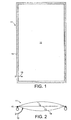
- FIG. 1 shows an ETFE cushion in accordance with the invention.
- the cushion 11 comprises three rectangular ETFE foil sheets 12, 13, 14, a support frame 15 and a plenum 16.
- the frame 15 is located about the perimeter of the sheets 12, 13, 14 and incorporates a release mechanism 17 (not shown).
- the space between the sheets 12, 13, 14 is inflated with air via the plenum 16.
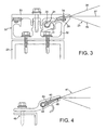
- Figure 3 shows a first embodiment of release mechanism.
- the overall arrangement comprises a cushion 21, a support frame 22 and a building structure 23.
- the cushion 21 has a bead 24 at its perimeter made from a rope 25 encapsulated by an extended portion of the sheets 26, 27, 28. Between the bead 24 and the inflated part of the cushion 21, there is an edge support 29. The bead 24 is captured within a keder edge 31, made from aluminium.
- the frame 22 comprises a housing 32 and a cap 33.
- the keder edge 31 is clipped into the housing 32 and the cap 33 is bolted into the housing 32 to form a weather-tight seal.
- the housing 32 is itself bolted to the structure 23.
- the edge support 29 includes an electrical resistance cable 34 extending around the perimeter of the cushion 21, or at least around three miles. When required, current is passed through the cable 34, raising its temperature to a level where the ETFE foil 26, 27, 28 or the support 29 fails and the cushion 21 is freed from the frame 22.
- FIG. 4 The variant shown in Figure 4 is similar to that of Figure 3, but in this case, the bead 44 of the cushion 41 is located in a compressible gasket 42 made for example of EPDM which is itself swaged into a retaining channel 43 forming part of the frame 45. Again, there is a resistance cable 46 in contact with the foil of the cushion 41 which causes the foil to fail when current is passed.
- a compressible gasket 42 made for example of EPDM
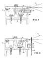
- Figure 5 shows a second embodiment.
- the cushion 51 is located within the frame 52 by means of a peripheral bead 53 including a rope 54, the bead being captured by a keder edge 55 which is clipped into the frame housing 56.
- the rope 54 is wound round a pulley 57 and connected to a winch (not shown).
- the rope 54 is drawn by a winch, and the bead 53 collapses. As a result, the cushion 51 is released.
- Figure 6 shows a third embodiment.
- the cushion 61 is located within the frame 62 by means of a peripheral bead 63 captured by a keder edge 54 clipped into the frame housing 65.
- a blade 66 is provided on a carriage 67 which is arranged to be rotatable and to travel along a track 68 around at least three sides of the periphery of the cushion 61, when required, cutting through the cushion foils to free the cushion 61.
- the blade 66 is shown located below the cushion it could equally well be above.
- the blade 66 is shown in its deployed position, cutting through the foils. It is to be understood that in its normal position, the blade 66 would not make contact with the foils. When required, the blade 66 would be swung into the deployed position and moved along the cushion 61. There may be a separate blade 66 for each side of the cushion 61.
- Figures 7 and 8 show a fourth embodiment.
- the cushion 71 is located within the frame 72 by means of a peripheral bead 73 captured by a keder edge 74 clipped into the frame housing 75.
- the foils, between the bead 73 and the inflated part of the cushion 71 are supported on and held along each edge by a hinged member 76 forming part of the housing 75.
- Each hinged member 76 is pivoted about an axle 77.
- Each hinged member 76 is held in its normal position, engaging the foils, by a series of levers 78 which are pivotally connected to the frame 72 by pins 79.
- the levers 78 are connected together by connecting rods 81 and one lever is connected to a pneumatic or hydraulic ram 82.
- the ram 82 associated with each side is operated. This draws the levers 78 towards the ram 82, rotating them clockwise about the pins 79 to the positions shown in broken lines. This in turn allows the hinged member 79 to pivot downwards about the axle 77 to the positions shown in broken lines, so releasing the cushion 71 from the housing 75.
Abstract
Description
- The present invention relates to building components, particularly, but not exclusively, for roofing, in the form of inflatable cushions. The cushions comprise two or more layers of a plastic foil material such as ETFE (ethylene tetra flouro ethylene) inflated with low pressure air. The ETFE foil cushion is restrained in a perimeter frame usually manufactured from extruded aluminium, which in turn is fixed to a support structure. As the ETFE foil cushion is inflated, the ETFE is put under tension and forms a tight drum like skin. ETFE foil cushions are sold under a number of trade names, for example Texlon.
- ETFE cushions of this kind are fixed to a support structure to form a cladding and are used to enclose atria or other enclosed spaces to provide a transparent or translucent roof or façade to the enclosure, as an alternative to and in a similar way to glass. A number of buildings have been built using this technology most notably the Eden project in Cornwall, England.
- Whenever a space is enclosed by a cladding system due consideration needs to be given to the effects of a fire should it break out in the building. In these circumstances, smoke and other products of combustion must be ventilated from the enclosure to prevent injury to the occupants and property. In some specialist buildings, other noxious fumes may also need to be ventilated from the enclosure to prevent injury to the occupants and property. In some specialist buildings, other noxious fumes may also need to be ventilated to atmosphere.
- Typically this is achieved in two main ways.
- Firstly, the smoke, and/or fumes can be extracted by a mechanical extraction system usually consisting of fire-rated duct work and extraction fans.
- Alternatively, the smoke and/or fumes can be extracted by opening part of the roof or building façade and allowing the smoke to ventilate to atmosphere through the action of convection and/or wind.
- ETFE foil cushions can be used to ventilate smoke and/or fumes to the atmosphere in much the same ways as other cladding systems in that they can be fixed to a frame which opens automatically through a mechanical device in the event of fire. In addition, ETFE is a thermo-plastic material and therefore has the innate property of failing if the temperature reaches approximately 200°C, as the material loses its tensile properties as its temperature increases. When the cushion fails, it allows smoke and/or fumes to ventilate naturally to the atmosphere.
- The above methods suffer from a number of draw backs. The mechanical extraction approach is expensive and requires fire-rated machinery, regular maintenance and testing. Natural extraction requires expensive opening frames, which are complex to render, weather and watertight. They do not look the same as the adjacent cladding as they require a secondary opening frame, and mechanical operating parts which themselves require regular maintenance and testing. The failure of the ETFE due to high temperature does not occur if the building fire is located some way away from the ETFE, as the ETFE is not sufficiently heated by smoke and/or fumes to fail.
- US-A-4 878 322 describes a building component with all of the features of the preamble of claim 1, in that it discloses a skeletal frame supporting a continuous sealed, flattened plastic film tube for retaining gas under positive pressure, whereby the tube has opposed edges with a flexible film retainer line passing therethrough to form edge beads.
- It is an object of the present invention to provide an economical, visually unobtrusive, method of causing ETFE foil cladding systems to fail on demand in order to allow natural smoke ventilation from a building enclosure.
- It is a further object of the invention to allow the system to fail on demand in order to shed high loads such as snow or water ponding.
- Thus, according to one aspect, the present invention provides a building component in the form of an inflatable cushion comprising two or more sheets of plastics foil attached by connecting means to a relatively rigid frame surrounding and supporting the foil sheets, the building component further incorporating a release mechanism in or adjacent to the frame arranged to release the foil sheets from the frame.
- Preferably, the sheets are made from ethylene tetrafluoro ethylene (ETFE).
Preferably, the sheets define a space between them which is inflated with air and the frame restrains the sheets about their perimeters, thereby forming the cushion. The release mechanism may extend the entire periphery of the cushion. Alternatively, it may extend only part of the way around, for example, in the case of a polygonal cushion, it may extend around all sides except one. In the case of a rectangular cushion, therefore, it might extend around three sides. - Preferably, the cushion has a bead formed around its periphery, and the bead is located within the frame. The bead may be a rope encapsulated by the sheet material. The bead may be held by a keder edge within the frame.
- The frame may be manufactured from extruded aluminium which in turn may be fixed to a support structure. The frame incorporates a device which releases the ETFE foil cushion from the frame in the event of fire so allowing the smoke to ventilate to atmosphere.
- There are two principal ways of releasing the ETFE foil cushion from the frame: mechanically releasing the cushion or cutting it free. In the case of mechanical release, this may be achieved by either extracting the rope from the bead which restrains the ETFE foil cushion in the frame, or by hinging a part of the frame so that it releases the keder edge.
- Preferably, therefore the release mechanism comprises a device which removes the rope from the bead on demand, releasing the ETFE foil cushion from the frame. Suitable means for removing the rope include by a mechanical winch, or ram, block and tackle. This can be done via a turning wheel. Alternatively, the release mechanism may comprise a hinged member engaging the cushion, the hinged member being movable on demand to a position in which it does not engage the cushion, thereby releasing the cushion from the frame.
- In the case of cutting the cushion free, preferably, the frame incorporates a cutting device which either physically cuts or melts the ETFE foil along the edge of the cushion. Preferably therefore, the release mechanism comprises an electrical resistance cable which causes the edge of the cushion to melt on demand, releasing the ETFE foil cushion from the frame. Alternatively, the release mechanism may comprise a cutting blade adjacent to the perimeter frame, and a means for moving the cutting blade so that on demand, the blade moves, cutting the ETFE foil cushion, thereby releasing the ETFE foil cushion from the frame.
- The cutting blade can be situated either above or below the inflated cushion.
Suitable means for moving the blade include a mechanical winch, ram or block and tackle. - Whichever mechanism is used, on release from the frame, the ETFE moves away from the frame so allowing the products of combustion or other noxious fumes to ventilate to atmosphere. On operation of the release mechanism on one or more sides, the ETFE foil cushion may form a cylindrical or spherical shape due to retention of pressurised air in the cushion; flap or fall away from one or more sides of the frame; or flap or fall away from all sides of the frame. In any event the removal of the cushion from all or part of the frame will allow smoke or noxious fumes to ventilate from the building. It will also allow any excessive water or snow loads to be released.
- The invention may be carried into practice in a number of ways and four embodiments will now be described by way of example with reference to the accompanying drawings, in which:
- Figure 1 is a plan of an ETFE cushion in accordance with the present invention;
- Figure 2 is a cross section through the assembly of Figure 1;
- Figure 3 is a detailed cross section of the perimeter cushion frame showing one embodiment of release mechanism;
- Figure 4 is a detailed cross section of an alternative perimeter cushion frame showing a variant of the first embodiment of release mechanism;
- Figure 5 is a detailed cross section of the perimeter cushion frame showing a second embodiment of release mechanism;
- Figure 6 is a detailed cross section of the perimeter cushion frame showing a third embodiment of release mechanism;
- Figure 7 is a detailed cross section of a perimeter cushion frame showing a fourth embodiment of release mechanism; and
- Figure 8 is an elevation of Figure 7.
- Figure 1 shows an ETFE cushion in accordance with the invention. The
cushion 11 comprises three rectangularETFE foil sheets support frame 15 and aplenum 16. Theframe 15 is located about the perimeter of thesheets sheets plenum 16. - Figure 3 shows a first embodiment of release mechanism. The overall arrangement comprises a
cushion 21, asupport frame 22 and abuilding structure 23. Thecushion 21 has abead 24 at its perimeter made from arope 25 encapsulated by an extended portion of thesheets bead 24 and the inflated part of thecushion 21, there is anedge support 29. Thebead 24 is captured within akeder edge 31, made from aluminium. - The
frame 22 comprises ahousing 32 and acap 33. Thekeder edge 31 is clipped into thehousing 32 and thecap 33 is bolted into thehousing 32 to form a weather-tight seal. Thehousing 32 is itself bolted to thestructure 23. - The
edge support 29 includes anelectrical resistance cable 34 extending around the perimeter of thecushion 21, or at least around three miles. When required, current is passed through thecable 34, raising its temperature to a level where theETFE foil support 29 fails and thecushion 21 is freed from theframe 22. - The variant shown in Figure 4 is similar to that of Figure 3, but in this case, the
bead 44 of thecushion 41 is located in acompressible gasket 42 made for example of EPDM which is itself swaged into a retainingchannel 43 forming part of theframe 45. Again, there is aresistance cable 46 in contact with the foil of thecushion 41 which causes the foil to fail when current is passed. - Figure 5 shows a second embodiment. Again, the
cushion 51 is located within theframe 52 by means of aperipheral bead 53 including arope 54, the bead being captured by akeder edge 55 which is clipped into theframe housing 56. However, in this embodiment, there is no resistance wire. Instead, therope 54 is wound round apulley 57 and connected to a winch (not shown). Thus, when required, therope 54 is drawn by a winch, and thebead 53 collapses. As a result, thecushion 51 is released. - Figure 6 shows a third embodiment. In this case, the
cushion 61 is located within theframe 62 by means of aperipheral bead 63 captured by akeder edge 54 clipped into theframe housing 65. However, in this embodiment, ablade 66 is provided on acarriage 67 which is arranged to be rotatable and to travel along atrack 68 around at least three sides of the periphery of thecushion 61, when required, cutting through the cushion foils to free thecushion 61. Although theblade 66 is shown located below the cushion it could equally well be above. - The
blade 66 is shown in its deployed position, cutting through the foils. It is to be understood that in its normal position, theblade 66 would not make contact with the foils. When required, theblade 66 would be swung into the deployed position and moved along thecushion 61. There may be aseparate blade 66 for each side of thecushion 61. - Figures 7 and 8 show a fourth embodiment. In this case the
cushion 71 is located within theframe 72 by means of aperipheral bead 73 captured by a keder edge 74 clipped into theframe housing 75. However, in this embodiment, the foils, between thebead 73 and the inflated part of thecushion 71 are supported on and held along each edge by a hingedmember 76 forming part of thehousing 75. Each hingedmember 76 is pivoted about anaxle 77. - Each hinged
member 76 is held in its normal position, engaging the foils, by a series oflevers 78 which are pivotally connected to theframe 72 bypins 79. Thelevers 78 are connected together by connectingrods 81 and one lever is connected to a pneumatic orhydraulic ram 82. - When it is desired to release the
cushion 71, theram 82 associated with each side is operated. This draws thelevers 78 towards theram 82, rotating them clockwise about thepins 79 to the positions shown in broken lines. This in turn allows the hingedmember 79 to pivot downwards about theaxle 77 to the positions shown in broken lines, so releasing thecushion 71 from thehousing 75. - It will be appreciated that the arrangements shown in the third and fourth embodiments could be combined, to allow the cushion to be released downwards to the blade. It will also be appreciated that, as with the earlier embodiments, the release mechanism described can act on three sides or all four sides of the cushion.
- As will also be understood, when the cushion is released, smoke can be ventilated and/or any accumulated excess snow or water loads can be released.
Claims (15)
- A building component in the form of an inflatable cushion (11) comprising two or more sheets (12,13,14) of plastics foil attached by connecting means (24,25,29,31,32,34; 42,43,44,46; 74,76) to a relatively rigid frame (15) surrounding and supporting the foil sheets (12,13,14), characterised in that the building component further incorporates a release mechanism (17) in or adjacent to the frame (15) arranged to release the foil sheets (12,13,14) from the frame (15).
- A building component as claimed in Claim 1, characterised in that the sheets (12,13,14) are made from ethylene tetrafluoro ethylene (ETFE).
- A building component as claimed in Claim 1 or Claim 2, characterised in that two of the sheets (12,13,14) define a space between them which is inflated with air and the frame (15) restrains the sheets (12,13,14) about their perimeters, thereby forming the cushion (11).
- A building component as claimed in any preceding Claim, characterised in that the release mechanism (17) extends around the entire periphery of the cushion (11).
- A building component as claimed in any preceding Claim, characterised in that the cushion (21) has a bead (24) formed around its periphery, and the bead (24) is located within the frame (22).
- A building component as claimed in Claim 5, characterised in that the bead (24) is a rope (25) encapsulated by the sheet material.
- A building component as claimed in Claim 6, characterised in that the bead (24) is held by a keder edge (31) within the frame (22).
- A building component as claimed in any preceding Claim, characterised in that the release mechanism (17) comprises an electrical resistance cable (34) arranged to cause the cushion (21) to melt at its periphery on demand, thereby releasing the cushion (21) from the frame (22).
- A building component as claimed in Claim 7, characterised in that the release mechanism comprises a device which removes the rope (54) from the bead (53) on demand, thereby releasing the cushion (51) from the frame (52).
- A building component as claimed in Claim 9, characterised in that the device which removes the rope (54) is a winch.
- A building component as claimed in any of Claims 1 to 7, characterised in that the release mechanism comprises a cutting blade (66) adjacent to the frame (62) and a means (67) for moving the cutting blade (66) along the periphery, whereby on demand, the cutting blade (66) moves and cuts the foil, thereby releasing the cushion (61) from the frame.
- A building component as claimed in Claim 11, characterised in that the means for moving the cutting blade (66) is a winch or a ram.
- A building component as claimed in any of Claims 1 to 7, characterised in that the release mechanism comprises a hinged member (76) engaging the cushion (71), the hinged member (76) being movable on demand to a position in which it does not engage the cushion (71), thereby releasing the cushion (71) from the frame (72).
- A building component as claimed in Claim 13, characterised in that the hinged member (76) is moved by levers (78) operated by a ram (82).
- A cladding system for a building comprising a plurality of components as claimed in any preceding Claim, the frames of which are attached to a structure.
Applications Claiming Priority (2)
| Application Number | Priority Date | Filing Date | Title |
|---|---|---|---|
| GB0207643A GB2387183B (en) | 2002-04-02 | 2002-04-02 | Building component |
| GB0207643 | 2002-04-02 |
Publications (3)
| Publication Number | Publication Date |
|---|---|
| EP1350906A2 EP1350906A2 (en) | 2003-10-08 |
| EP1350906A3 EP1350906A3 (en) | 2004-01-28 |
| EP1350906B1 true EP1350906B1 (en) | 2006-11-08 |
Family
ID=9934135
Family Applications (1)
| Application Number | Title | Priority Date | Filing Date |
|---|---|---|---|
| EP03251982A Expired - Lifetime EP1350906B1 (en) | 2002-04-02 | 2003-03-28 | Building component |
Country Status (9)
| Country | Link |
|---|---|
| US (4) | US7127851B2 (en) |
| EP (1) | EP1350906B1 (en) |
| AT (1) | ATE344864T1 (en) |
| DE (1) | DE60309531T2 (en) |
| DK (1) | DK1350906T3 (en) |
| ES (1) | ES2276010T3 (en) |
| GB (1) | GB2387183B (en) |
| HK (1) | HK1061414A1 (en) |
| PT (1) | PT1350906E (en) |
Cited By (1)
| Publication number | Priority date | Publication date | Assignee | Title |
|---|---|---|---|---|
| DE102009013729A1 (en) | 2009-03-20 | 2010-09-23 | Seele Holding Gmbh & Co. Kg | Membrane component for use in e.g. roof, of building, has membrane element whose side is detachable from holding profile by relative changing of cross-section of welt or cross-section of gap of tracks |
Families Citing this family (34)
| Publication number | Priority date | Publication date | Assignee | Title |
|---|---|---|---|---|
| US7406802B2 (en) * | 2003-03-19 | 2008-08-05 | Awi Licensing Company | Panel structures and mounting therefore |
| DE102004025310A1 (en) * | 2004-05-19 | 2005-12-15 | Georg Andreas Huber | Structural component for making diaphragm has padding materials extended in retaining groove of frame profile between boundary regions of diaphragms and side walls of retaining groove, where boundary regions are between padding materials |
| DE102004025307A1 (en) * | 2004-05-19 | 2005-12-22 | Georg Andreas Huber | Diaphragm construction unit for e.g. wall, of building, has edges connected to one other by adhesive connected blanks that are formed of polymer foil that has fluorine, where adhesive is composition of hydro silicon modified poly ether |
| US20050279465A1 (en) * | 2004-06-18 | 2005-12-22 | Ted Gower | Structure envelope reinforcement |
| CA2477797C (en) * | 2004-09-01 | 2006-05-23 | Edouard P. Kassianoff | Tensioned inflatable cover module |
| DE102005037386A1 (en) | 2005-08-08 | 2007-02-15 | Mankau, Dieter, Prof. Dr. | Pneumatic body |
| GB0525681D0 (en) * | 2005-12-16 | 2006-01-25 | Denholm Defence Ltd | Covering apparatus |
| GB0614253D0 (en) * | 2006-07-18 | 2006-08-30 | Solar Century Holdings Ltd | Flexible solar roof |
| WO2008069658A1 (en) | 2006-12-04 | 2008-06-12 | Van Diemen B.V. | Roof construction for a cultivation space |
| NL2000470C2 (en) * | 2007-02-02 | 2008-08-05 | Diemen B V Van | Roof for cultivation space e.g. greenhouse of space unit, has film webs which extend from inlet and lie against one another and folded over the top part of attachment profile to delimit the volume of cushion |
| US7516577B1 (en) * | 2006-12-08 | 2009-04-14 | Hendee Enterprises, Inc. | Fabric structures with tensioner and tensioner device |
| DE102007001376B4 (en) * | 2007-01-09 | 2009-04-16 | Greiner, Switbert, Dr. | Membrane element and method for covering surfaces |
| FR2919646B1 (en) * | 2007-08-01 | 2009-09-11 | Ferrari S Tissage & Enduct Sa | DOUBLE-SKIN SOFT WALL AND DEVICE FOR MAINTAINING A DOUBLE-SKIN FLEXIBLE WALL |
| JP5003670B2 (en) * | 2007-12-27 | 2012-08-15 | 大成建設株式会社 | Building envelope structure |
| US7871052B2 (en) * | 2008-03-18 | 2011-01-18 | John Baum | Flexible cover hold down system |
| US20100077686A1 (en) * | 2008-09-26 | 2010-04-01 | Dockside Canvas Co. | Decorative display |
| DE102008050457A1 (en) * | 2008-10-08 | 2010-04-29 | Elnic Gmbh | Method for purging bubble inflation air for foil cushion designed component for roof or facade construction, involves providing air drying- or dehumidification device and supplying fresh air to air drying- or dehumidification device |
| SG172429A1 (en) * | 2008-12-30 | 2011-07-28 | 3M Innovative Properties Co | Architectural articles comprising a fluoropolymeric multilayer optical film and methods of making the same |
| DE202010015743U1 (en) * | 2010-11-24 | 2012-03-01 | Vector Foiltec Gmbh | Building cladding element with thermal insulation element |
| DE102010055461B4 (en) * | 2010-12-21 | 2013-07-11 | Greiner & Gutmann Gbr | Cladding and fastening and clamping devices |
| DE102010055462A1 (en) * | 2010-12-21 | 2012-06-21 | Greiner & Gutmann Gbr | paneling |
| US8959854B1 (en) | 2011-05-25 | 2015-02-24 | Management Resources Group, LLC | Weatherproof fabric-covered building system |
| CN102508504B (en) * | 2011-11-14 | 2013-05-08 | 上海交通大学 | ETFE air pillow structural test constant pressure control system |
| US8763309B2 (en) * | 2012-06-05 | 2014-07-01 | Walter P. Moore & Associates | Deployable and inflatable roof, wall, or other structure for stadiums and other venues |
| DE102013001170B3 (en) * | 2013-01-24 | 2014-05-28 | seele group GmbH & Co. KG | Holding device for fastening membrane constructions |
| US9038349B2 (en) | 2013-07-19 | 2015-05-26 | Benjamin D. Fox | Keder rail attachment for a fabric/panel building |
| US9422732B2 (en) | 2014-04-28 | 2016-08-23 | Ted Gower | Slidable barriers |
| US9388576B2 (en) | 2014-07-02 | 2016-07-12 | John Bowen | Trim assembly for a flexible panel in a false ceiling |
| US9512612B2 (en) | 2014-12-05 | 2016-12-06 | Ted Gower | Retainer inserts for barriers |
| JP6709747B2 (en) * | 2017-03-30 | 2020-06-17 | 協立工業株式会社 | Membrane structure |
| DE102017129059A1 (en) * | 2017-12-06 | 2019-06-06 | Vector Foiltec Gmbh | Device for discharging a liquid and building envelope elements with such a device |
| JP7094536B2 (en) * | 2018-02-14 | 2022-07-04 | 協立工業株式会社 | Membrane structure and sheet fixing part |
| DE102018127912A1 (en) | 2018-11-08 | 2020-05-14 | Vector Foiltec Gmbh | Building cladding element with a film element |
| CN113898130A (en) * | 2021-10-23 | 2022-01-07 | 北京城建集团有限责任公司 | Connecting structure of drainage ditch, laminated wood and ETFE (ethylene-propylene-diene monomer) membrane and mounting method |
Family Cites Families (15)
| Publication number | Priority date | Publication date | Assignee | Title |
|---|---|---|---|---|
| CH489396A (en) * | 1968-09-17 | 1970-04-30 | Wilhelm Thiel Alfons | Double-walled plastic article, process for its manufacture and device for carrying out the process |
| US3738253A (en) * | 1971-11-24 | 1973-06-12 | Wasco Products | Fire and smoke ventilator |
| US3788013A (en) * | 1972-06-07 | 1974-01-29 | Hillsdale Ind Inc | Drop away fire vent |
| US3996650A (en) * | 1975-09-29 | 1976-12-14 | Tonn Martin H | Film retainer member for solar heater chamber |
| DE7623114U1 (en) * | 1976-07-22 | 1976-12-09 | Hochstein, Alfred, 4150 Krefeld | INFLATABLE STRUCTURE |
| US4144325A (en) * | 1976-11-10 | 1979-03-13 | Voyt Walter F | Method of and composition for preventing sunburn while affording tanning |
| DE2925637A1 (en) * | 1979-06-26 | 1981-01-15 | Bp Benzin Und Petroleum Ag | THERMAL INSULATING WALL AND / OR COVERING ELEMENT FOR HALLS AND THE LIKE |
| US4387533A (en) * | 1980-08-01 | 1983-06-14 | Green George H | Method and apparatus for retaining heat in greenhouse and similar structures |
| US4878322A (en) * | 1987-08-10 | 1989-11-07 | Ikege, Inc. | Insulating plastic film structures and method |
| US4807405A (en) * | 1987-08-20 | 1989-02-28 | Borgquist Ronald B | Geodesic inflatable structure, and methods of constructing and utilizing same |
| US5027564A (en) * | 1988-05-09 | 1991-07-02 | Colux Gesellschaft fur Licht - und Leichtbau mbH | Building construction with a chamber which can be acted upon by a fluid medium |
| GB9517500D0 (en) * | 1995-08-25 | 1995-10-25 | J T Inglis & Sons Limited | Shelter structures |
| CA2190796C (en) * | 1995-11-22 | 2002-07-02 | Wendell B. Colson | Ceiling cladding system |
| US6668491B1 (en) * | 1997-03-03 | 2003-12-30 | Timothy C. Bonerb | Device for removing ice from roofs |
| US6161348A (en) * | 1999-03-25 | 2000-12-19 | C/S Construction Specialties Limited | Drop-out fire vent |
-
2002
- 2002-04-02 GB GB0207643A patent/GB2387183B/en not_active Expired - Lifetime
-
2003
- 2003-03-28 DK DK03251982T patent/DK1350906T3/en active
- 2003-03-28 ES ES03251982T patent/ES2276010T3/en not_active Expired - Lifetime
- 2003-03-28 DE DE60309531T patent/DE60309531T2/en not_active Expired - Lifetime
- 2003-03-28 EP EP03251982A patent/EP1350906B1/en not_active Expired - Lifetime
- 2003-03-28 AT AT03251982T patent/ATE344864T1/en not_active IP Right Cessation
- 2003-03-28 PT PT03251982T patent/PT1350906E/en unknown
- 2003-03-31 US US10/403,466 patent/US7127851B2/en not_active Expired - Lifetime
-
2004
- 2004-04-02 HK HK04102440A patent/HK1061414A1/en not_active IP Right Cessation
-
2006
- 2006-10-27 US US11/588,936 patent/US7415799B2/en not_active Expired - Lifetime
- 2006-10-27 US US11/588,938 patent/US7434357B2/en not_active Expired - Lifetime
- 2006-10-27 US US11/588,937 patent/US7434356B2/en not_active Expired - Lifetime
Cited By (2)
| Publication number | Priority date | Publication date | Assignee | Title |
|---|---|---|---|---|
| DE102009013729A1 (en) | 2009-03-20 | 2010-09-23 | Seele Holding Gmbh & Co. Kg | Membrane component for use in e.g. roof, of building, has membrane element whose side is detachable from holding profile by relative changing of cross-section of welt or cross-section of gap of tracks |
| DE202009019056U1 (en) | 2009-03-20 | 2016-01-28 | seele group GmbH & Co. KG | Membranbaukomponente |
Also Published As
| Publication number | Publication date |
|---|---|
| EP1350906A3 (en) | 2004-01-28 |
| DK1350906T3 (en) | 2007-03-19 |
| GB2387183B (en) | 2005-07-27 |
| US7127851B2 (en) | 2006-10-31 |
| US7434356B2 (en) | 2008-10-14 |
| HK1061414A1 (en) | 2004-09-17 |
| DE60309531D1 (en) | 2006-12-21 |
| US20070039249A1 (en) | 2007-02-22 |
| US20070039251A1 (en) | 2007-02-22 |
| EP1350906A2 (en) | 2003-10-08 |
| ATE344864T1 (en) | 2006-11-15 |
| US7415799B2 (en) | 2008-08-26 |
| US7434357B2 (en) | 2008-10-14 |
| GB2387183A (en) | 2003-10-08 |
| PT1350906E (en) | 2007-01-31 |
| GB0207643D0 (en) | 2002-05-15 |
| DE60309531T2 (en) | 2007-06-28 |
| US20070039250A1 (en) | 2007-02-22 |
| US20030208963A1 (en) | 2003-11-13 |
| ES2276010T3 (en) | 2007-06-16 |
Similar Documents
| Publication | Publication Date | Title |
|---|---|---|
| EP1350906B1 (en) | Building component | |
| US4672888A (en) | Inflatable greenhouse vent cover | |
| EP2326797A1 (en) | Ventilation system for railway tunnels | |
| CA2628249A1 (en) | Moveable soffit vent cover system and associated methods | |
| CA2411528C (en) | Low profile vehicle escape hatch assembly | |
| US4815365A (en) | Self-ventilating greenhouse | |
| EP1281314A2 (en) | Ventilation device for hothouse | |
| WO2018190455A1 (en) | Fog removal apparatus and multipurpose fog removal system including the same | |
| KR101189010B1 (en) | Accumulate device for signify the emergency accidient of tunnel | |
| EP3877612B1 (en) | Building-sheath element having a sheet-material element | |
| US20130344793A1 (en) | Ventilation arrangement | |
| KR0128228B1 (en) | Air vinly house | |
| WO2008055452A1 (en) | Protective device for an existing, locally fixed object or structure as well as the application of such a protective device | |
| KR20180024551A (en) | Facility for protecting stock | |
| CN112901242B (en) | Auxiliary explosion door system for coal mine air shaft air guide chamber | |
| CN214783213U (en) | Protective structure and bridge device | |
| CN217131777U (en) | Medicinal material sunning canopy | |
| GB2087459A (en) | Method and Means for Closing Underground Passageways | |
| JP4199162B2 (en) | Membrane roof structure and its laying method | |
| CN113482866A (en) | Cabin cover and wind driven generator | |
| CN218063972U (en) | Flue gas exhaust pipeline tightly clamped and wrapped by glass wool | |
| CN218597394U (en) | Novel building waterproof structure | |
| JP2754990B2 (en) | Roof membrane support structure | |
| CN112663485A (en) | Protective structure and bridge device | |
| JPH0726733A (en) | Rain shielding installation |
Legal Events
| Date | Code | Title | Description |
|---|---|---|---|
| PUAI | Public reference made under article 153(3) epc to a published international application that has entered the european phase |
Free format text: ORIGINAL CODE: 0009012 |
|
| AK | Designated contracting states |
Kind code of ref document: A2 Designated state(s): AT BE BG CH CY CZ DE DK EE ES FI FR GB GR HU IE IT LI LU MC NL PT RO SE SI SK TR |
|
| AX | Request for extension of the european patent |
Extension state: AL LT LV MK |
|
| PUAL | Search report despatched |
Free format text: ORIGINAL CODE: 0009013 |
|
| AK | Designated contracting states |
Kind code of ref document: A3 Designated state(s): AT BE BG CH CY CZ DE DK EE ES FI FR GB GR HU IE IT LI LU MC NL PT RO SE SI SK TR |
|
| AX | Request for extension of the european patent |
Extension state: AL LT LV MK |
|
| RIC1 | Information provided on ipc code assigned before grant |
Ipc: 7E 04B 7/08 B Ipc: 7E 04H 15/20 A |
|
| 17P | Request for examination filed |
Effective date: 20040629 |
|
| AKX | Designation fees paid |
Designated state(s): AT BE BG CH CY CZ DE DK EE ES FI FR GB GR HU IE IT LI LU MC NL PT RO SE SI SK TR |
|
| AXX | Extension fees paid |
Extension state: AL Payment date: 20040629 Extension state: MK Payment date: 20040629 Extension state: LV Payment date: 20040629 Extension state: LT Payment date: 20040629 |
|
| GRAP | Despatch of communication of intention to grant a patent |
Free format text: ORIGINAL CODE: EPIDOSNIGR1 |
|
| RBV | Designated contracting states (corrected) |
Designated state(s): AT BE BG CH CY CZ DE DK EE ES FI FR GR HU IE IT LI LU MC NL PT RO SE SI SK TR |
|
| GRAS | Grant fee paid |
Free format text: ORIGINAL CODE: EPIDOSNIGR3 |
|
| GRAA | (expected) grant |
Free format text: ORIGINAL CODE: 0009210 |
|
| AK | Designated contracting states |
Kind code of ref document: B1 Designated state(s): AT BE BG CH CY CZ DE DK EE ES FI FR GR HU IE IT LI LU MC NL PT RO SE SI SK TR |
|
| AX | Request for extension of the european patent |
Extension state: AL LT LV MK |
|
| PG25 | Lapsed in a contracting state [announced via postgrant information from national office to epo] |
Ref country code: BE Free format text: LAPSE BECAUSE OF FAILURE TO SUBMIT A TRANSLATION OF THE DESCRIPTION OR TO PAY THE FEE WITHIN THE PRESCRIBED TIME-LIMIT Effective date: 20061108 Ref country code: AT Free format text: LAPSE BECAUSE OF FAILURE TO SUBMIT A TRANSLATION OF THE DESCRIPTION OR TO PAY THE FEE WITHIN THE PRESCRIBED TIME-LIMIT Effective date: 20061108 Ref country code: SK Free format text: LAPSE BECAUSE OF FAILURE TO SUBMIT A TRANSLATION OF THE DESCRIPTION OR TO PAY THE FEE WITHIN THE PRESCRIBED TIME-LIMIT Effective date: 20061108 Ref country code: SI Free format text: LAPSE BECAUSE OF FAILURE TO SUBMIT A TRANSLATION OF THE DESCRIPTION OR TO PAY THE FEE WITHIN THE PRESCRIBED TIME-LIMIT Effective date: 20061108 Ref country code: CH Free format text: LAPSE BECAUSE OF FAILURE TO SUBMIT A TRANSLATION OF THE DESCRIPTION OR TO PAY THE FEE WITHIN THE PRESCRIBED TIME-LIMIT Effective date: 20061108 Ref country code: FI Free format text: LAPSE BECAUSE OF FAILURE TO SUBMIT A TRANSLATION OF THE DESCRIPTION OR TO PAY THE FEE WITHIN THE PRESCRIBED TIME-LIMIT Effective date: 20061108 Ref country code: LI Free format text: LAPSE BECAUSE OF FAILURE TO SUBMIT A TRANSLATION OF THE DESCRIPTION OR TO PAY THE FEE WITHIN THE PRESCRIBED TIME-LIMIT Effective date: 20061108 Ref country code: RO Free format text: LAPSE BECAUSE OF FAILURE TO SUBMIT A TRANSLATION OF THE DESCRIPTION OR TO PAY THE FEE WITHIN THE PRESCRIBED TIME-LIMIT Effective date: 20061108 Ref country code: CZ Free format text: LAPSE BECAUSE OF FAILURE TO SUBMIT A TRANSLATION OF THE DESCRIPTION OR TO PAY THE FEE WITHIN THE PRESCRIBED TIME-LIMIT Effective date: 20061108 |
|
| REG | Reference to a national code |
Ref country code: CH Ref legal event code: EP |
|
| REG | Reference to a national code |
Ref country code: IE Ref legal event code: FG4D |
|
| REF | Corresponds to: |
Ref document number: 60309531 Country of ref document: DE Date of ref document: 20061221 Kind code of ref document: P |
|
| REG | Reference to a national code |
Ref country code: PT Ref legal event code: SC4A Free format text: AVAILABILITY OF NATIONAL TRANSLATION Effective date: 20070111 |
|
| PG25 | Lapsed in a contracting state [announced via postgrant information from national office to epo] |
Ref country code: BG Free format text: LAPSE BECAUSE OF FAILURE TO SUBMIT A TRANSLATION OF THE DESCRIPTION OR TO PAY THE FEE WITHIN THE PRESCRIBED TIME-LIMIT Effective date: 20070208 Ref country code: SE Free format text: LAPSE BECAUSE OF FAILURE TO SUBMIT A TRANSLATION OF THE DESCRIPTION OR TO PAY THE FEE WITHIN THE PRESCRIBED TIME-LIMIT Effective date: 20070208 |
|
| REG | Reference to a national code |
Ref country code: DK Ref legal event code: T3 |
|
| LTIE | Lt: invalidation of european patent or patent extension |
Effective date: 20061108 |
|
| ET | Fr: translation filed | ||
| REG | Reference to a national code |
Ref country code: CH Ref legal event code: PL |
|
| REG | Reference to a national code |
Ref country code: ES Ref legal event code: FG2A Ref document number: 2276010 Country of ref document: ES Kind code of ref document: T3 |
|
| PLBE | No opposition filed within time limit |
Free format text: ORIGINAL CODE: 0009261 |
|
| STAA | Information on the status of an ep patent application or granted ep patent |
Free format text: STATUS: NO OPPOSITION FILED WITHIN TIME LIMIT |
|
| 26N | No opposition filed |
Effective date: 20070809 |
|
| PG25 | Lapsed in a contracting state [announced via postgrant information from national office to epo] |
Ref country code: MC Free format text: LAPSE BECAUSE OF NON-PAYMENT OF DUE FEES Effective date: 20070331 |
|
| PG25 | Lapsed in a contracting state [announced via postgrant information from national office to epo] |
Ref country code: GR Free format text: LAPSE BECAUSE OF FAILURE TO SUBMIT A TRANSLATION OF THE DESCRIPTION OR TO PAY THE FEE WITHIN THE PRESCRIBED TIME-LIMIT Effective date: 20070209 |
|
| PGFP | Annual fee paid to national office [announced via postgrant information from national office to epo] |
Ref country code: IE Payment date: 20080604 Year of fee payment: 6 |
|
| PG25 | Lapsed in a contracting state [announced via postgrant information from national office to epo] |
Ref country code: EE Free format text: LAPSE BECAUSE OF FAILURE TO SUBMIT A TRANSLATION OF THE DESCRIPTION OR TO PAY THE FEE WITHIN THE PRESCRIBED TIME-LIMIT Effective date: 20061108 |
|
| PGFP | Annual fee paid to national office [announced via postgrant information from national office to epo] |
Ref country code: DK Payment date: 20090313 Year of fee payment: 7 |
|
| PGFP | Annual fee paid to national office [announced via postgrant information from national office to epo] |
Ref country code: PT Payment date: 20090324 Year of fee payment: 7 |
|
| PG25 | Lapsed in a contracting state [announced via postgrant information from national office to epo] |
Ref country code: LU Free format text: LAPSE BECAUSE OF NON-PAYMENT OF DUE FEES Effective date: 20070328 Ref country code: CY Free format text: LAPSE BECAUSE OF FAILURE TO SUBMIT A TRANSLATION OF THE DESCRIPTION OR TO PAY THE FEE WITHIN THE PRESCRIBED TIME-LIMIT Effective date: 20061108 |
|
| PGFP | Annual fee paid to national office [announced via postgrant information from national office to epo] |
Ref country code: TR Payment date: 20090305 Year of fee payment: 7 |
|
| PG25 | Lapsed in a contracting state [announced via postgrant information from national office to epo] |
Ref country code: HU Free format text: LAPSE BECAUSE OF FAILURE TO SUBMIT A TRANSLATION OF THE DESCRIPTION OR TO PAY THE FEE WITHIN THE PRESCRIBED TIME-LIMIT Effective date: 20070509 |
|
| PG25 | Lapsed in a contracting state [announced via postgrant information from national office to epo] |
Ref country code: IE Free format text: LAPSE BECAUSE OF NON-PAYMENT OF DUE FEES Effective date: 20090330 |
|
| REG | Reference to a national code |
Ref country code: DK Ref legal event code: EBP |
|
| PG25 | Lapsed in a contracting state [announced via postgrant information from national office to epo] |
Ref country code: PT Free format text: LAPSE BECAUSE OF NON-PAYMENT OF DUE FEES Effective date: 20100928 |
|
| PG25 | Lapsed in a contracting state [announced via postgrant information from national office to epo] |
Ref country code: DK Free format text: LAPSE BECAUSE OF NON-PAYMENT OF DUE FEES Effective date: 20100331 |
|
| PG25 | Lapsed in a contracting state [announced via postgrant information from national office to epo] |
Ref country code: TR Free format text: LAPSE BECAUSE OF NON-PAYMENT OF DUE FEES Effective date: 20100328 |
|
| REG | Reference to a national code |
Ref country code: FR Ref legal event code: PLFP Year of fee payment: 13 |
|
| REG | Reference to a national code |
Ref country code: FR Ref legal event code: PLFP Year of fee payment: 14 |
|
| REG | Reference to a national code |
Ref country code: DE Ref legal event code: R081 Ref document number: 60309531 Country of ref document: DE Owner name: VECTOR FOILTEC GMBH, DE Free format text: FORMER OWNER: MORRIS, BENEDICT GEORGE, LONDON, GB Ref country code: DE Ref legal event code: R082 Ref document number: 60309531 Country of ref document: DE Representative=s name: EISENFUEHR SPEISER PATENTANWAELTE RECHTSANWAEL, DE |
|
| REG | Reference to a national code |
Ref country code: FR Ref legal event code: PLFP Year of fee payment: 15 |
|
| REG | Reference to a national code |
Ref country code: FR Ref legal event code: PLFP Year of fee payment: 16 |
|
| PGFP | Annual fee paid to national office [announced via postgrant information from national office to epo] |
Ref country code: NL Payment date: 20210319 Year of fee payment: 19 Ref country code: FR Payment date: 20210322 Year of fee payment: 19 |
|
| PGFP | Annual fee paid to national office [announced via postgrant information from national office to epo] |
Ref country code: IT Payment date: 20210331 Year of fee payment: 19 Ref country code: DE Payment date: 20210407 Year of fee payment: 19 |
|
| PGFP | Annual fee paid to national office [announced via postgrant information from national office to epo] |
Ref country code: ES Payment date: 20210421 Year of fee payment: 19 |
|
| REG | Reference to a national code |
Ref country code: DE Ref legal event code: R119 Ref document number: 60309531 Country of ref document: DE |
|
| REG | Reference to a national code |
Ref country code: NL Ref legal event code: MM Effective date: 20220401 |
|
| PG25 | Lapsed in a contracting state [announced via postgrant information from national office to epo] |
Ref country code: NL Free format text: LAPSE BECAUSE OF NON-PAYMENT OF DUE FEES Effective date: 20220401 Ref country code: FR Free format text: LAPSE BECAUSE OF NON-PAYMENT OF DUE FEES Effective date: 20220331 Ref country code: DE Free format text: LAPSE BECAUSE OF NON-PAYMENT OF DUE FEES Effective date: 20221001 |
|
| REG | Reference to a national code |
Ref country code: ES Ref legal event code: FD2A Effective date: 20230504 |
|
| PG25 | Lapsed in a contracting state [announced via postgrant information from national office to epo] |
Ref country code: IT Free format text: LAPSE BECAUSE OF NON-PAYMENT OF DUE FEES Effective date: 20220328 |
|
| PG25 | Lapsed in a contracting state [announced via postgrant information from national office to epo] |
Ref country code: ES Free format text: LAPSE BECAUSE OF NON-PAYMENT OF DUE FEES Effective date: 20220329 |