EP1352773A1 - Method and apparatus for controlling vehicle cruise - Google Patents
Method and apparatus for controlling vehicle cruise Download PDFInfo
- Publication number
- EP1352773A1 EP1352773A1 EP03008031A EP03008031A EP1352773A1 EP 1352773 A1 EP1352773 A1 EP 1352773A1 EP 03008031 A EP03008031 A EP 03008031A EP 03008031 A EP03008031 A EP 03008031A EP 1352773 A1 EP1352773 A1 EP 1352773A1
- Authority
- EP
- European Patent Office
- Prior art keywords
- set speed
- driver
- deceleration
- vehicle
- speed
- Prior art date
- Legal status (The legal status is an assumption and is not a legal conclusion. Google has not performed a legal analysis and makes no representation as to the accuracy of the status listed.)
- Granted
Links
Images


Classifications
-
- B—PERFORMING OPERATIONS; TRANSPORTING
- B60—VEHICLES IN GENERAL
- B60K—ARRANGEMENT OR MOUNTING OF PROPULSION UNITS OR OF TRANSMISSIONS IN VEHICLES; ARRANGEMENT OR MOUNTING OF PLURAL DIVERSE PRIME-MOVERS IN VEHICLES; AUXILIARY DRIVES FOR VEHICLES; INSTRUMENTATION OR DASHBOARDS FOR VEHICLES; ARRANGEMENTS IN CONNECTION WITH COOLING, AIR INTAKE, GAS EXHAUST OR FUEL SUPPLY OF PROPULSION UNITS IN VEHICLES
- B60K31/00—Vehicle fittings, acting on a single sub-unit only, for automatically controlling vehicle speed, i.e. preventing speed from exceeding an arbitrarily established velocity or maintaining speed at a particular velocity, as selected by the vehicle operator
- B60K31/02—Vehicle fittings, acting on a single sub-unit only, for automatically controlling vehicle speed, i.e. preventing speed from exceeding an arbitrarily established velocity or maintaining speed at a particular velocity, as selected by the vehicle operator including electrically actuated servomechanism including an electric control system or a servomechanism in which the vehicle velocity affecting element is actuated electrically
- B60K31/04—Vehicle fittings, acting on a single sub-unit only, for automatically controlling vehicle speed, i.e. preventing speed from exceeding an arbitrarily established velocity or maintaining speed at a particular velocity, as selected by the vehicle operator including electrically actuated servomechanism including an electric control system or a servomechanism in which the vehicle velocity affecting element is actuated electrically and means for comparing one electrical quantity, e.g. voltage, pulse, waveform, flux, or the like, with another quantity of a like kind, which comparison means is involved in the development of an electrical signal which is fed into the controlling means
-
- B—PERFORMING OPERATIONS; TRANSPORTING
- B60—VEHICLES IN GENERAL
- B60W—CONJOINT CONTROL OF VEHICLE SUB-UNITS OF DIFFERENT TYPE OR DIFFERENT FUNCTION; CONTROL SYSTEMS SPECIALLY ADAPTED FOR HYBRID VEHICLES; ROAD VEHICLE DRIVE CONTROL SYSTEMS FOR PURPOSES NOT RELATED TO THE CONTROL OF A PARTICULAR SUB-UNIT
- B60W50/00—Details of control systems for road vehicle drive control not related to the control of a particular sub-unit, e.g. process diagnostic or vehicle driver interfaces
- B60W2050/0001—Details of the control system
- B60W2050/0019—Control system elements or transfer functions
- B60W2050/0022—Gains, weighting coefficients or weighting functions
-
- B—PERFORMING OPERATIONS; TRANSPORTING
- B60—VEHICLES IN GENERAL
- B60W—CONJOINT CONTROL OF VEHICLE SUB-UNITS OF DIFFERENT TYPE OR DIFFERENT FUNCTION; CONTROL SYSTEMS SPECIALLY ADAPTED FOR HYBRID VEHICLES; ROAD VEHICLE DRIVE CONTROL SYSTEMS FOR PURPOSES NOT RELATED TO THE CONTROL OF A PARTICULAR SUB-UNIT
- B60W50/00—Details of control systems for road vehicle drive control not related to the control of a particular sub-unit, e.g. process diagnostic or vehicle driver interfaces
- B60W2050/0001—Details of the control system
- B60W2050/0043—Signal treatments, identification of variables or parameters, parameter estimation or state estimation
- B60W2050/0052—Filtering, filters
-
- B—PERFORMING OPERATIONS; TRANSPORTING
- B60—VEHICLES IN GENERAL
- B60W—CONJOINT CONTROL OF VEHICLE SUB-UNITS OF DIFFERENT TYPE OR DIFFERENT FUNCTION; CONTROL SYSTEMS SPECIALLY ADAPTED FOR HYBRID VEHICLES; ROAD VEHICLE DRIVE CONTROL SYSTEMS FOR PURPOSES NOT RELATED TO THE CONTROL OF A PARTICULAR SUB-UNIT
- B60W2540/00—Input parameters relating to occupants
- B60W2540/30—Driving style
-
- B—PERFORMING OPERATIONS; TRANSPORTING
- B60—VEHICLES IN GENERAL
- B60W—CONJOINT CONTROL OF VEHICLE SUB-UNITS OF DIFFERENT TYPE OR DIFFERENT FUNCTION; CONTROL SYSTEMS SPECIALLY ADAPTED FOR HYBRID VEHICLES; ROAD VEHICLE DRIVE CONTROL SYSTEMS FOR PURPOSES NOT RELATED TO THE CONTROL OF A PARTICULAR SUB-UNIT
- B60W2710/00—Output or target parameters relating to a particular sub-units
- B60W2710/06—Combustion engines, Gas turbines
- B60W2710/0605—Throttle position
-
- B—PERFORMING OPERATIONS; TRANSPORTING
- B60—VEHICLES IN GENERAL
- B60W—CONJOINT CONTROL OF VEHICLE SUB-UNITS OF DIFFERENT TYPE OR DIFFERENT FUNCTION; CONTROL SYSTEMS SPECIALLY ADAPTED FOR HYBRID VEHICLES; ROAD VEHICLE DRIVE CONTROL SYSTEMS FOR PURPOSES NOT RELATED TO THE CONTROL OF A PARTICULAR SUB-UNIT
- B60W2710/00—Output or target parameters relating to a particular sub-units
- B60W2710/06—Combustion engines, Gas turbines
- B60W2710/0616—Position of fuel or air injector
-
- B—PERFORMING OPERATIONS; TRANSPORTING
- B60—VEHICLES IN GENERAL
- B60W—CONJOINT CONTROL OF VEHICLE SUB-UNITS OF DIFFERENT TYPE OR DIFFERENT FUNCTION; CONTROL SYSTEMS SPECIALLY ADAPTED FOR HYBRID VEHICLES; ROAD VEHICLE DRIVE CONTROL SYSTEMS FOR PURPOSES NOT RELATED TO THE CONTROL OF A PARTICULAR SUB-UNIT
- B60W2720/00—Output or target parameters relating to overall vehicle dynamics
- B60W2720/10—Longitudinal speed
- B60W2720/106—Longitudinal acceleration
Definitions
- the present invention relates to a method and an apparatus for controlling a vehicle cruise, and more particularly to a method and apparatus for controlling an actual vehicle speed, which is a running speed of a vehicle, to a set speed desired by a driver to hold the vehicle at the fixed vehicle speed.
- a known vehicle cruise control apparatus of the type mentioned above involves calculating a target acceleration or deceleration from a deviation of an actual vehicle speed from a set speed instructed by a driver, and controlling a throttle valve based on the target acceleration or deceleration to accomplish vehicle cruise.
- Another known vehicle cruise control apparatus involves calculating a look-ahead vehicle speed, which anticipates an actual vehicle speed, based on the actual vehicle speed and an actual acceleration, calculating a target acceleration or deceleration based on a deviation of the look-ahead vehicle speed from a set speed instructed by a driver and a look-ahead acceleration, and controlling a throttle actuator based on the target acceleration or deceleration to accomplish vehicle cruise.
- JP-A-9-86224 and JP-A-2000-108716 disclose prior art techniques related to vehicle cruise control apparatuses of the type mentioned above.
- the present invention has been made in view of the circumstance mentioned above, and it is an object of the invention to provide a vehicle cruise control apparatus which is capable of reflecting a set speed inputted by a driver to a target acceleration or deceleration to accomplish a behavior of a vehicle which follows the driver's will.
- the present invention provides a vehicle cruise control apparatus which includes an actuator mounted in a vehicle for adjusting a running speed of the vehicle, an operating switch for setting a vehicle speed desired by a driver, driver set speed input state storage means for storing an input state when the driver operates the operating switch, actual vehicle speed detecting means for detecting the actual vehicle speed which is a running speed of the vehicle, means for calculating a vehicle speed deviation of the actual vehicle speed (or a look-ahead vehicle speed) from the set speed set by the driver, means for calculating a target acceleration/deceleration from the driver set speed input state and the vehicle speed deviation, and/or means for controlling the actuator to satisfy the target acceleration/deceleration.
- Fig. 1 is a block diagram generally illustrating the configuration of a vehicle cruise control apparatus according to one embodiment of the present invention.
- a vehicle cruise controller 1 receives information from a vehicle speed sensor 4, and receives information on a set speed desired by a driver from an operating switch 3, calculates a target acceleration/deceleration to match an actual vehicle speed with the set speed, and outputs the target acceleration/deceleration to an engine controller 5.
- the engine controller 5 drives an engine 7 and a throttle actuator 6 based on the target acceleration/deceleration received from the vehicle cruise controller 1 to control the opening of a throttle valve, thereby increasing or decreasing the power of the engine 7.
- the vehicle cruise controller 1 or engine controller 5 When a transmission 9 must be controlled, the vehicle cruise controller 1 or engine controller 5 outputs an instruction to a transmission controller 8 to conduct a control for the transmission 9.
- the operating switch 3 comprises an acceleration switch 12 and a deceleration switch 13 for the driver to input a desired set speed Vs.
- the set speed Vs is often in a range of 40 to 120 km/h, for example, in Japan.
- the set speed is typically between a lower limit which is approximately 40 km/h and an upper limit which is approximately 110 - 120 km/h in consideration of high ways, hill climbing, or the like.
- the set speed Vs is increased by a set speed width (in this example, 5 km/h) such as 80, 85, 90, 95, ..., km/h, by way of example.
- a set speed width in this example, 5 km/h
- the set speed Vs is reduced by a certain speed width (which may be equal to or different from the increased width).
- the resulting vehicle speed Vs is stored in a set speed storage unit 10.
- the set speed Vs is increased or decreased by a fixed speed width, however, the speed width may be variable.
- the vehicle cruise control can follow the driver's will when the speed width is corresponded to a switch input frequency variable Sf, later described.
- the set speed Vs may be increased or decreased in steps of 1 km/h for the first two seconds, and subsequently in steps of 5 km/h.
- driver set speed input state storage unit 11 stores an input state of the operating switch 3, indicative of the frequency at which the driver pushes the operating switch 3, and whether the driver pushes the acceleration switch 12 or deceleration switch 13. Also, as shown in Fig. 3, the vehicle cruise controller 1 takes a logical OR of an acceleration switch input signal Sat and a deceleration switch input signal Sdt to generate a switch input variable St(SatUSdt), and generates a switch input frequency variable Sf based on the duration of the switch input variable St from a falling (OFF) edge to a rising (ON) edge. A procedure for processing the switch input frequency variable Sf will be described in detail with reference to Figs. 11 to 13. A flow chart in Fig.
- step 11 illustrating the processing on the switch input frequency variable Sf is repeated every control period.
- the switch input variable St is ON (step 100).
- the switch input variable St is ON, it is next determined whether or not the preceding value (St one period before) Stn-1 of the switch input variable is OFF (step 106).
- the preceding value Stn-1 of the switch input variable is OFF, it can be determined that a transition from OFF to ON of the switch input variable ST is detected as is done at timing t1 in Fig. 13.
- the switch input frequency Sfp is derived based on a OFF-to-ON duration variable Ct.
- FIG. 12 shows an exemplary characteristic of the switch input frequency Sfp which is an output to the OFF-to-ON duration variable Ct at step 107 in Fig. 11.
- the switch input frequency Sfp is substituted into the switch input frequency variable Sf (step 108), and the OFF-to-ON duration variable Ct is cleared for measuring again the duration between the falling edge (OFF) and the next rising edge (ON).
- the switch input frequency Sfp is derived in a manner similar to that at step 107 (step 102). It is next determined whether or not the switch input frequency Sfp is smaller than the switch input frequency variable Sf (step 103). When the switch input frequency Sfp is smaller than the switch input frequency variable Sf, it is determined that the switch input frequency variable Sf has a value larger than the actual switch input frequency Sfp, caused by the operating switch 3 which has not been operated, as can be seen between timings t3 and t4 in Fig. 13. Then, the switch input frequency Sfp is substituted into the switch input frequency variable Sf. In addition, the OFF-to-ON duration variable Ct is incremented to continuously measure the time for which the switch remains OFF.
- the vehicle cruise controller 1 generates an acceleration/deceleration direction variable Sd based on an acceleration switch input signal Sat and a deceleration switch input signal Sdt.
- the acceleration/deceleration direction variable Sd takes "1" when acceleration is instructed and "-1" when deceleration is instructed.
- the vehicle cruise controller 1 generates a driver set speed input state variable Ss which is calculated by multiplying the aforementioned switch input frequency variable Sf by the acceleration/deceleration direction variable Sd.
- the set speed Vs is changed in steps in this embodiment, so that a very large target acceleration/deceleration can be calculated only at the moment the set speed Vs is changed, as shown in Fig. 14, resulting in bad running feeling.
- the set speed Vs is filtered (in a block 33) to generate a second set speed Vs2 which continuously vary, as shown in Fig. 4.
- This second set speed Vs2 is employed for calculating the target acceleration/deceleration.
- Vs2 Vs
- This processing advantageously increases the resolution of the set speed, thereby permitting the set speed to smoothly vary.
- the second set speed Vs2 which excessively promptly follows Vs would make Vs2_z1 equal to Vs2, whereas the second set speed Vs2 which sluggishly follows Vs, i.e., which presents a poor response would cause the driver to experience a stress.
- the set speed Vs is filtered to ensure a desired response characteristic.
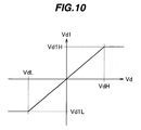
- Fig. 10 shows an exemplary characteristic of the second vehicle speed deviation Vd1 which is an output corresponding to the vehicle speed deviation Vd in the filtering 33.
- the second vehicle speed deviation Vd1 is limited to Vd1H when the vehicle speed deviation Vd is equal to or higher than a predefined upper limit VdH, and is limited to a second vehicle speed deviation Vd1L when the vehicle speed deviation Vd is equal to or lower than a predefined lower limit value VdL, thereby preventing an excessively large target acceleration/deceleration from being calculated when the set speed Vs changes in steps as shown in Fig. 15.
- Vd2 Vs2 - Vn
- the target acceleration/deceleration map 30 is two-dimensional map data which takes the vehicle speed deviation Vd2 on the horizontal axis and the driver set speed input state variable Ss on the vertical axis, as shown in Fig. 5, wherein a particular target acceleration/deceleration is assigned to each grid point (coordinates (Vd2, Ss)).
- Vd2, Ss coordinates
- a second embodiment of the running control apparatus will be described with reference to Figs. 6 and 7. While the second embodiment is the same as the first embodiment in the general configuration, the second embodiment employs a different method for calculating the target acceleration/deceleration.
- the target acceleration/deceleration is calculated in the following manner.
- the set speed Vs is filtered in a filtering block 14 to derive a target vehicle speed Vc.
- a vehicle speed deviation Vdf of the actual vehicle speed Vn from the target vehicle speed Vc is calculated, and divided by a control period Tn to derive the target acceleration/deceleration :
- a filtering constant Tf [s] used in the filtering block 14 is found from a two-dimensional filtering constant map 31 which depends on the absolute value
- a first-order low pass filter is used for the filtering block 14, so that a particular time constant Tf is assigned to each grid point in the map as shown in Fig. 7.
- An intermediate value between two grid points is calculated through linear interpolation, whereas a value out of the map is limited to data of map end.
- the vehicle cruise control apparatus in the second embodiment determines that the driver wishes a sudden acceleration when the driver continuously pushes the acceleration switch 12 to increase the set speed Vs, and responsively generates a large target acceleration/deceleration, as shown in Fig. 9 so that the vehicle can reach the maximum acceleration in a shorter time (between timings t1 and t3 in Fig. 8) than the prior art technique (between t1 and t4).
- the vehicle cruise control apparatus can determine that the driver wishes a slow acceleration when the driver is continually pushing the acceleration switch 12 at long intervals, and on the contrary, can determine that the driver wishes a sudden acceleration when the driver is continually pushing the acceleration switch 12 at short intervals.
- the operating switch when the operating switch is operated at a high frequency (i.e., when the driver continuously changes the set speed), the absolute value of the target acceleration/deceleration is increased so that the response of vehicle behavior becomes quicker to a change in the set speed.
- the operating switch when the operating switch is operated at a low frequency (i.e., when the driver changes the set speed at one time), the behavior of the vehicle can be controlled to gradually match the vehicle speed with a change in the set speed by reducing the absolute value of the target acceleration/deceleration (gradually increasing the target acceleration/deceleration in a negative range).
- the vehicle speed deviation Vd still has a positive value (the set speed is higher than the actual vehicle speed), so that the target acceleration/deceleration also has a positive value.
- the driver set speed input state variable Ss has a large negative value, so that the target acceleration deceleration can be reduced to a smaller value, thereby resulting in a prompt transition from acceleration to deceleration.
- the target acceleration/deceleration can be set to a smaller value in response to a request for a sudden deceleration which is made after a request for a sudden acceleration, thereby making it possible to make a prompt transition from acceleration to deceleration.
- the vehicle cruise control apparatus can prevent an unintended acceleration which could result even in case the driver pushed the deceleration switch, as experienced in the prior art.
- the vehicle can be controlled to promptly decelerate, as indicated by a solid line in Fig. 9, when the driver operates the deceleration switch twice, while the vehicle is actually running at 80 Km/h, to change the set speed from 110 km/h to 100 km/h.
- the vehicle cruise control apparatus can reduce a deceleration, even when the vehicle speed deviation has a negative value (the set speed is lower than the actual vehicle speed), to transition the control in the accelerating direction at an earlier time upon detection of a high frequency at which the driver operates the acceleration switch.
- the vehicle cruise control apparatus can reduce an acceleration, even when the vehicle speed deviation has a positive value (the set speed is higher than the actual vehicle speed), to transition the control in the decelerating direction at an earlier time upon detection of a high frequency at which the driver operates the deceleration switch.
- the vehicle cruise control apparatus can accomplish the vehicle cruise control which can reflect the driver's will and improve the running feeling.
- the vehicle cruise control apparatus can improve a sluggish acceleration, a delayed deceleration and the like, which run counter to the driver's will, as experienced with the prior art illustrated in Fig. 8, to accomplish the vehicle cruise control which follows the driver's will.
Abstract
Description
- The present invention relates to a method and an apparatus for controlling a vehicle cruise, and more particularly to a method and apparatus for controlling an actual vehicle speed, which is a running speed of a vehicle, to a set speed desired by a driver to hold the vehicle at the fixed vehicle speed.
- A known vehicle cruise control apparatus of the type mentioned above involves calculating a target acceleration or deceleration from a deviation of an actual vehicle speed from a set speed instructed by a driver, and controlling a throttle valve based on the target acceleration or deceleration to accomplish vehicle cruise. Another known vehicle cruise control apparatus involves calculating a look-ahead vehicle speed, which anticipates an actual vehicle speed, based on the actual vehicle speed and an actual acceleration, calculating a target acceleration or deceleration based on a deviation of the look-ahead vehicle speed from a set speed instructed by a driver and a look-ahead acceleration, and controlling a throttle actuator based on the target acceleration or deceleration to accomplish vehicle cruise.
- JP-A-9-86224 and JP-A-2000-108716 disclose prior art techniques related to vehicle cruise control apparatuses of the type mentioned above.
- However, since the prior art control apparatuses mentioned above calculate the target acceleration or deceleration from the vehicle speed deviation (deviation of the actual vehicle speed from the set speed) for controlling the vehicle to run at a constant speed, the driver's will cannot be always reflected to the control. Assume, for example, that the driver inputs a set speed, which can cause overshooting, in order to eventually increase a vehicle speed from Vn0 to Vng, as shown in Fig. 8.
- In this event, as the vehicle speed deviation of the actual vehicle speed from the set speed gradually increases from timing t1 in Fig. 8, causing a target acceleration to correspondingly increase to a maximum acceleration at timing t4 in Fig. 8, in which case, however, the acceleration from timing t1 to timing t4 in Fig. 8 is felt rather slow, causing the driver to feel awkward. In addition, the acceleration is gradually reduced between timings t6 and t7 in Fig. 8, in which the vehicle speed deviation begins to decrease, after the vehicle has accelerated to the maximum acceleration (between timings t4 and t6 in Fig. 8), whereas the vehicle speed deviation still has a positive value, and a relatively large acceleration is maintained until timing t7 in Fig. 8 at which the set speed intersects the actual vehicle speed, i.e., at which the vehicle speed deviation decreases to zero (Vs-Vn=0 km/h), so that a subsequent deceleration is delayed (t7 - t10). Consequently, the actual vehicle speed is delayed with respect to the set speed, causing the vehicle to feel awkward.
- The present invention has been made in view of the circumstance mentioned above, and it is an object of the invention to provide a vehicle cruise control apparatus which is capable of reflecting a set speed inputted by a driver to a target acceleration or deceleration to accomplish a behavior of a vehicle which follows the driver's will.
- To achieve the above object, the present invention provides a vehicle cruise control apparatus which includes an actuator mounted in a vehicle for adjusting a running speed of the vehicle, an operating switch for setting a vehicle speed desired by a driver, driver set speed input state storage means for storing an input state when the driver operates the operating switch, actual vehicle speed detecting means for detecting the actual vehicle speed which is a running speed of the vehicle, means for calculating a vehicle speed deviation of the actual vehicle speed (or a look-ahead vehicle speed) from the set speed set by the driver, means for calculating a target acceleration/deceleration from the driver set speed input state and the vehicle speed deviation, and/or means for controlling the actuator to satisfy the target acceleration/deceleration.
-
- Fig. 1 is a block diagram generally illustrating the configuration of a vehicle cruise control apparatus according to one embodiment of the present invention;
- Fig. 2 is a block diagram generally illustrating a vehicle cruise controller in Fig. 1;
- Fig. 3 is a timing chart used to calculate a driver set speed input state variable Ss;
- Fig. 4 is a block diagram illustrating a target acceleration/deceleration calculation unit in a first embodiment;
- Fig. 5 shows a target acceleration/deceleration map used in the first embodiment;
- Fig. 6 is a block diagram illustrating a target acceleration/deceleration calculation unit in a second embodiment;
- Fig. 7 shows a filtering constant map used in the second embodiment;
- Fig. 8 is a timing chart showing a set speed, an actual vehicle speed and a target acceleration/deceleration during a vehicle cruise control according to a prior art technique;
- Fig. 9 is a timing chart showing a set speed, an actual vehicle speed and a target acceleration/deceleration during a vehicle cruise control according to the present invention;
- Fig. 10 is a graph showing a characteristic of a second vehicle speed deviation Vd1 in the first embodiment;
- Fig. 11 is a flow chart illustrating a procedure for processing a switch input frequency variable Sf in the first embodiment;
- Fig. 12 is a graph showing a characteristic of a switch input frequency Sfp in the first embodiment;
- Fig. 13 is a timing chart used to calculate the switch input frequency variable Sf in the first embodiment;
- Fig. 14 is a timing chart used to calculate the target acceleration/deceleration based on the actual vehicle speed Vn and set speed Vs; and
- Fig. 15 is a timing chart used to calculate the target acceleration/deceleration based on the actual vehicle speed Vn and second set speed Vs2.
-
- In the following, the present invention will be described in connedtion with an embodiment with reference to Figs. 1 to 15.
- Fig. 1 is a block diagram generally illustrating the configuration of a vehicle cruise control apparatus according to one embodiment of the present invention. A
vehicle cruise controller 1 receives information from avehicle speed sensor 4, and receives information on a set speed desired by a driver from anoperating switch 3, calculates a target acceleration/deceleration to match an actual vehicle speed with the set speed, and outputs the target acceleration/deceleration to anengine controller 5. Theengine controller 5 drives anengine 7 and athrottle actuator 6 based on the target acceleration/deceleration received from thevehicle cruise controller 1 to control the opening of a throttle valve, thereby increasing or decreasing the power of theengine 7. - When a
transmission 9 must be controlled, thevehicle cruise controller 1 orengine controller 5 outputs an instruction to atransmission controller 8 to conduct a control for thetransmission 9. - Next, a process performed in the
vehicle cruise controller 1 to derive the target acceleration/deceleration will be described with reference to Figs. 2 and 3. Referring first to Fig. 2, theoperating switch 3 comprises anacceleration switch 12 and adeceleration switch 13 for the driver to input a desired set speed Vs. The set speed Vs is often in a range of 40 to 120 km/h, for example, in Japan. At present, since the low speed running control cannot support open roads, the set speed is typically between a lower limit which is approximately 40 km/h and an upper limit which is approximately 110 - 120 km/h in consideration of high ways, hill climbing, or the like. - When the driver operates the
acceleration switch 12 in theoperating switch 3, the set speed Vs is increased by a set speed width (in this example, 5 km/h) such as 80, 85, 90, 95, ..., km/h, by way of example. When the driver operates thedeceleration switch 13, the set speed Vs is reduced by a certain speed width (which may be equal to or different from the increased width). The resulting vehicle speed Vs is stored in a setspeed storage unit 10. In this embodiment, the set speed Vs is increased or decreased by a fixed speed width, however, the speed width may be variable. For example, the vehicle cruise control can follow the driver's will when the speed width is corresponded to a switch input frequency variable Sf, later described. Specifically, when the driver keeps pushing theacceleration switch 12 ordeceleration switch 13 down, the set speed Vs may be increased or decreased in steps of 1 km/h for the first two seconds, and subsequently in steps of 5 km/h. - Next, driver set speed input
state storage unit 11 stores an input state of theoperating switch 3, indicative of the frequency at which the driver pushes theoperating switch 3, and whether the driver pushes theacceleration switch 12 ordeceleration switch 13. Also, as shown in Fig. 3, thevehicle cruise controller 1 takes a logical OR of an acceleration switch input signal Sat and a deceleration switch input signal Sdt to generate a switch input variable St(SatUSdt), and generates a switch input frequency variable Sf based on the duration of the switch input variable St from a falling (OFF) edge to a rising (ON) edge. A procedure for processing the switch input frequency variable Sf will be described in detail with reference to Figs. 11 to 13. A flow chart in Fig. 11 illustrating the processing on the switch input frequency variable Sf is repeated every control period. In Fig. 11, it is first determined whether or not the switch input variable St is ON (step 100). When the switch input variable St is ON, it is next determined whether or not the preceding value (St one period before) Stn-1 of the switch input variable is OFF (step 106). When the preceding value Stn-1 of the switch input variable is OFF, it can be determined that a transition from OFF to ON of the switch input variable ST is detected as is done at timing t1 in Fig. 13. Thus, the switch input frequency Sfp is derived based on a OFF-to-ON duration variable Ct. Fig. 12 shows an exemplary characteristic of the switch input frequency Sfp which is an output to the OFF-to-ON duration variable Ct atstep 107 in Fig. 11. Next, in Fig. 11, the switch input frequency Sfp is substituted into the switch input frequency variable Sf (step 108), and the OFF-to-ON duration variable Ct is cleared for measuring again the duration between the falling edge (OFF) and the next rising edge (ON). - When the preceding value Stn-1 of the switch input variable is ON at
step 106 in Fig. 11, it is determined that the switch input is kept ON as can be seen between timings t5 and t6 in Fig. 13, and the OFF-to-ON duration variable Ct is cleared (step 105), without updating the switch input frequency variable Sf. - At
step 100 in Fig. 11, when the switch input variable St is OFF, the switch input frequency Sfp is derived in a manner similar to that at step 107 (step 102). It is next determined whether or not the switch input frequency Sfp is smaller than the switch input frequency variable Sf (step 103). When the switch input frequency Sfp is smaller than the switch input frequency variable Sf, it is determined that the switch input frequency variable Sf has a value larger than the actual switch input frequency Sfp, caused by theoperating switch 3 which has not been operated, as can be seen between timings t3 and t4 in Fig. 13. Then, the switch input frequency Sfp is substituted into the switch input frequency variable Sf. In addition, the OFF-to-ON duration variable Ct is incremented to continuously measure the time for which the switch remains OFF. - When the switch input frequency Sfp is equal to or higher than the switch input frequency variable Sf at
step 103 in Fig. 11, this means that the switch has been left unoperated, as can be seen between timings t1 and t2 in Fig. 13, so that no value can be determined for the switch input frequency Sf until the next detection of a transition of the switch from the OFF state to the ON state. Therefore, in this event, the switch input frequency variable Sf is not updated. - Referring next to Fig. 3, description will be made on a method of generating a driver set speed input state variable Ss based on the switch input frequency variable Sf. First, the
vehicle cruise controller 1 generates an acceleration/deceleration direction variable Sd based on an acceleration switch input signal Sat and a deceleration switch input signal Sdt. The acceleration/deceleration direction variable Sd takes "1" when acceleration is instructed and "-1" when deceleration is instructed. In addition, thevehicle cruise controller 1 generates a driver set speed input state variable Ss which is calculated by multiplying the aforementioned switch input frequency variable Sf by the acceleration/deceleration direction variable Sd. - Next, a procedure for driving the target acceleration/deceleration will be described with reference to Fig. 4. A vehicle speed deviation Vd can be calculated by the following equation based on an actual vehicle speed Vn and the set speed Vs:
- When the target acceleration/deceleration is calculated based on the vehicle speed deviation Vd, the set speed Vs is changed in steps in this embodiment, so that a very large target acceleration/deceleration can be calculated only at the moment the set speed Vs is changed, as shown in Fig. 14, resulting in bad running feeling. To avoid this inconvenience, in this embodiment, the set speed Vs is filtered (in a block 33) to generate a second set speed Vs2 which continuously vary, as shown in Fig. 4. This second set speed Vs2 is employed for calculating the target acceleration/deceleration. In this embodiment, the second set speed Vs2 is calculated by the following equation using a second vehicle speed deviation Vd1 and a second set speed Vs2_z1 in the preceding control period:
- Assume herein that the second set speed Vs2 is initialized to Vs (Vs2=Vs) upon start of the vehicle cruise control.
- This processing advantageously increases the resolution of the set speed, thereby permitting the set speed to smoothly vary. However, the second set speed Vs2 which excessively promptly follows Vs would make Vs2_z1 equal to Vs2, whereas the second set speed Vs2 which sluggishly follows Vs, i.e., which presents a poor response would cause the driver to experience a stress. Thus, the set speed Vs is filtered to ensure a desired response characteristic.
- Fig. 10 shows an exemplary characteristic of the second vehicle speed deviation Vd1 which is an output corresponding to the vehicle speed deviation Vd in the
filtering 33. The second vehicle speed deviation Vd1 is limited to Vd1H when the vehicle speed deviation Vd is equal to or higher than a predefined upper limit VdH, and is limited to a second vehicle speed deviation Vd1L when the vehicle speed deviation Vd is equal to or lower than a predefined lower limit value VdL, thereby preventing an excessively large target acceleration/deceleration from being calculated when the set speed Vs changes in steps as shown in Fig. 15. Further, the second vehicle speed deviation Vd2 is calculated from the following equation, and the target acceleration/deceleration is derived from the second vehicle speed deviation Vd2 and input state variable Ss using a target acceleration/deceleration map 30: - Here, the target acceleration/
deceleration map 30 is two-dimensional map data which takes the vehicle speed deviation Vd2 on the horizontal axis and the driver set speed input state variable Ss on the vertical axis, as shown in Fig. 5, wherein a particular target acceleration/deceleration is assigned to each grid point (coordinates (Vd2, Ss)). An intermediate value between two grid points is calculated through linear interpolation, whereas a value out of the map is limited to data of map end. - Next, a second embodiment of the running control apparatus will be described with reference to Figs. 6 and 7. While the second embodiment is the same as the first embodiment in the general configuration, the second embodiment employs a different method for calculating the target acceleration/deceleration.
- As shown in Fig. 6, the target acceleration/deceleration is calculated in the following manner. The set speed Vs is filtered in a
filtering block 14 to derive a target vehicle speed Vc. A vehicle speed deviation Vdf of the actual vehicle speed Vn from the target vehicle speed Vc is calculated, and divided by a control period Tn to derive the target acceleration/deceleration : - A filtering constant Tf [s] used in the
filtering block 14 is found from a two-dimensional filteringconstant map 31 which depends on the absolute value |Ss| of the driver set speed input state variable Ss and the absolute value |Vd| of the vehicle speed deviation Vd. Here, a first-order low pass filter is used for thefiltering block 14, so that a particular time constant Tf is assigned to each grid point in the map as shown in Fig. 7. An intermediate value between two grid points is calculated through linear interpolation, whereas a value out of the map is limited to data of map end. - As described above, the vehicle cruise control apparatus in the second embodiment determines that the driver wishes a sudden acceleration when the driver continuously pushes the
acceleration switch 12 to increase the set speed Vs, and responsively generates a large target acceleration/deceleration, as shown in Fig. 9 so that the vehicle can reach the maximum acceleration in a shorter time (between timings t1 and t3 in Fig. 8) than the prior art technique (between t1 and t4). Specifically, the vehicle cruise control apparatus can determine that the driver wishes a slow acceleration when the driver is continually pushing theacceleration switch 12 at long intervals, and on the contrary, can determine that the driver wishes a sudden acceleration when the driver is continually pushing theacceleration switch 12 at short intervals. In this way, when the operating switch is operated at a high frequency (i.e., when the driver continuously changes the set speed), the absolute value of the target acceleration/deceleration is increased so that the response of vehicle behavior becomes quicker to a change in the set speed. On the other hand, when the operating switch is operated at a low frequency (i.e., when the driver changes the set speed at one time), the behavior of the vehicle can be controlled to gradually match the vehicle speed with a change in the set speed by reducing the absolute value of the target acceleration/deceleration (gradually increasing the target acceleration/deceleration in a negative range). - Between timings t6 and t7 in Fig. 9 in which the vehicle speed deviation Vd begins decreasing, the vehicle speed deviation Vd still has a positive value (the set speed is higher than the actual vehicle speed), so that the target acceleration/deceleration also has a positive value. However, at the time the
deceleration switch 13 is pushed (at timing t6 in Fig. 9), the driver set speed input state variable Ss has a large negative value, so that the target acceleration deceleration can be reduced to a smaller value, thereby resulting in a prompt transition from acceleration to deceleration. Specifically, assuming that thedeceleration switch 13 is pushed when the driver can request a sudden acceleration, it can be determined that the driver requests a sudden deceleration from a request for a sudden acceleration, with a higher probability than when the driver, who has not operated any switch, operates thedeceleration switch 13. This situation can be distinguished from a situation in which the driver, who has not operated any switch, operates the deceleration switch. Thus, as described above, the target acceleration/deceleration can be set to a smaller value in response to a request for a sudden deceleration which is made after a request for a sudden acceleration, thereby making it possible to make a prompt transition from acceleration to deceleration. Consequently, the vehicle cruise control apparatus according to the present invention can prevent an unintended acceleration which could result even in case the driver pushed the deceleration switch, as experienced in the prior art. For example, the vehicle can be controlled to promptly decelerate, as indicated by a solid line in Fig. 9, when the driver operates the deceleration switch twice, while the vehicle is actually running at 80 Km/h, to change the set speed from 110 km/h to 100 km/h. - As described above, the vehicle cruise control apparatus according to the present invention can reduce a deceleration, even when the vehicle speed deviation has a negative value (the set speed is lower than the actual vehicle speed), to transition the control in the accelerating direction at an earlier time upon detection of a high frequency at which the driver operates the acceleration switch. Similarly, the vehicle cruise control apparatus can reduce an acceleration, even when the vehicle speed deviation has a positive value (the set speed is higher than the actual vehicle speed), to transition the control in the decelerating direction at an earlier time upon detection of a high frequency at which the driver operates the deceleration switch.
- According to the present invention, since the target acceleration/deceleration can be varied based on how the driver operates the operating switch, the vehicle cruise control apparatus can accomplish the vehicle cruise control which can reflect the driver's will and improve the running feeling.
- The vehicle cruise control apparatus according to the present invention can improve a sluggish acceleration, a delayed deceleration and the like, which run counter to the driver's will, as experienced with the prior art illustrated in Fig. 8, to accomplish the vehicle cruise control which follows the driver's will.
Claims (6)
- A vehicle cruise control apparatus for controlling a vehicle to run at a set speed desired by a driver, said apparatus comprising:actual vehicle speed detecting means (4) for detecting an actual speed of the vehicle;setting means (12; 13) for allowing the driver to operate a desired set speed;set speed storage means (10) for storing the set speed;driver set speed input state detecting means (11) for detecting a state in which the driver inputs the set speed using said setting means;target acceleration/deceleration calculating means (2) for calculating a target acceleration/deceleration based on the driver set speed input state and a vehicle speed deviation when the target acceleration/deceleration is calculated to match the actual vehicle speed with the set speed; andmeans for controlling a throttle actuator (6) based on the target acceleration/deceleration to increase or decrease the engine power.
- A vehicle cruise control apparatus according to claim 1, wherein:said target acceleration/deceleration calculating means (2) calculates a large absolute target value for the target acceleration/deceleration so that the actual vehicle speed promptly follows the set speed, when said driver set speed input state detecting means (11) determines based on a detected driver set speed input state that the driver changes the set speed at a high frequency, andsaid target acceleration/deceleration calculating means (2) calculates a small absolute target value for the target acceleration/deceleration so that the actual vehicle speed slowly follows the set speed, when said driver set speed input state detecting means (11) determines that the driver changes the set speed at a low frequency.
- A vehicle cruise control apparatus according to claim 2, whereinsaid target acceleration/deceleration calculating means (2) gradually reduces the target acceleration/deceleration within a positive range even when the vehicle speed deviation takes a positive value to promptly transition from a accelerating state to a decelerating state, when said driver set speed input state detecting means (11) determines based on the driver set speed input state that the driver inputs a sudden deceleration instruction; andsaid target acceleration/deceleration calculating means (2) gradually reduces the absolute value of the target acceleration/deceleration within a negative range even when the vehicle speed deviation takes a negative value to promptly transition from a decelerating state to an accelerating state, when said driver set speed input state detecting means (11) determines based on the driver set speed input state that the driver inputs a sudden acceleration instruction.
- A vehicle cruise control method comprising the steps of:reading a vehicle speed set by a passenger; andcontrolling an actual vehicle speed based on an input state represented by a frequency at which the passenger changes the set speed, and a currently set speed.
- A vehicle cruise control method according to claim 4, further comprising the steps of:outputting a signal for controlling at least one of a throttle valve control system or a fuel injection valve based on the input state and the set speed; andcontrolling an acceleration of a vehicle to bring the actual vehicle speed to the set speed.
- A vehicle cruise control method according to claim 5, wherein said vehicle has a larger absolute value of acceleration as the driver changes the set speed at a higher frequency.
Applications Claiming Priority (2)
| Application Number | Priority Date | Filing Date | Title |
|---|---|---|---|
| JP2002108684A JP3746245B2 (en) | 2002-04-11 | 2002-04-11 | Constant speed travel control device |
| JP2002108684 | 2002-04-11 |
Publications (2)
| Publication Number | Publication Date |
|---|---|
| EP1352773A1 true EP1352773A1 (en) | 2003-10-15 |
| EP1352773B1 EP1352773B1 (en) | 2005-09-14 |
Family
ID=28449956
Family Applications (1)
| Application Number | Title | Priority Date | Filing Date |
|---|---|---|---|
| EP03008031A Expired - Lifetime EP1352773B1 (en) | 2002-04-11 | 2003-04-11 | Method and apparatus for controlling vehicle cruise |
Country Status (4)
| Country | Link |
|---|---|
| US (1) | US6865471B2 (en) |
| EP (1) | EP1352773B1 (en) |
| JP (1) | JP3746245B2 (en) |
| DE (1) | DE60301587T2 (en) |
Cited By (3)
| Publication number | Priority date | Publication date | Assignee | Title |
|---|---|---|---|---|
| WO2007039810A1 (en) * | 2005-10-05 | 2007-04-12 | Toyota Jidosha Kabushiki Kaisha | Deceleration control apparatus and method for vehicle |
| FR2933645A1 (en) * | 2008-07-09 | 2010-01-15 | Renault Sas | Motor vehicle speed limiting method, involves calculating control force from reference speed and transmitting force for regulating real speed of vehicle, and calculating reference speed as function of setpoint speed and real speed |
| CN115503707A (en) * | 2022-10-26 | 2022-12-23 | 东风商用车有限公司 | Cruise control method and system based on acceleration management and storage medium |
Families Citing this family (10)
| Publication number | Priority date | Publication date | Assignee | Title |
|---|---|---|---|---|
| US9583096B2 (en) * | 2006-08-15 | 2017-02-28 | Nuance Communications, Inc. | Enhancing environment voice macros via a stackable save/restore state of an object within an environment controlled by voice commands for control of vehicle components |
| DE102006060554A1 (en) * | 2006-12-21 | 2008-06-26 | Bayerische Motoren Werke Ag | Steering wheel for a motor vehicle and motor vehicle |
| EP2111347A4 (en) * | 2007-01-30 | 2011-08-03 | Gordon Ewbank Dower | Vehicle power and speed control systems |
| JP4930446B2 (en) * | 2008-04-14 | 2012-05-16 | トヨタ自動車株式会社 | Vehicle travel control device |
| US20090281703A1 (en) * | 2008-05-12 | 2009-11-12 | Hudson Meilleur | Cruise control cancel device for passengers in vehicles |
| US8055427B2 (en) * | 2008-12-18 | 2011-11-08 | GM Global Technology Operations LLC | Method and apparatus for speed-limit following cruise control |
| EP2404803A4 (en) * | 2009-03-06 | 2016-08-10 | Toyota Motor Co Ltd | Vehicle travel control device |
| CN110001654B (en) * | 2019-05-06 | 2023-07-28 | 吉林大学 | Intelligent vehicle longitudinal speed tracking control system and control method for self-adaptive driver type |
| KR20220048144A (en) * | 2020-10-12 | 2022-04-19 | 현대자동차주식회사 | Method for controlling driving force of vehicle |
| CN114148324A (en) * | 2021-11-30 | 2022-03-08 | 奇瑞新能源汽车股份有限公司 | Cruise control method and device for vehicle, vehicle and storage medium |
Citations (3)
| Publication number | Priority date | Publication date | Assignee | Title |
|---|---|---|---|---|
| US4598370A (en) * | 1983-01-27 | 1986-07-01 | Honda Giken Kogyo Kabushiki Kaisha | Apparatus for control of acceleration and deceleration during auto-cruise |
| US4835696A (en) * | 1986-08-28 | 1989-05-30 | Nissan Motor Company, Ltd. | System and method for automatically controlling a vehicle speed to a desired cruising speed |
| US4939657A (en) * | 1987-10-28 | 1990-07-03 | Mazda Motor Corporation | Constant-speed cruising control system |
Family Cites Families (7)
| Publication number | Priority date | Publication date | Assignee | Title |
|---|---|---|---|---|
| US4046213A (en) * | 1976-02-23 | 1977-09-06 | Eaton Corporation | Control system and method for controlling vehicle speed |
| EP0227198B1 (en) * | 1985-12-26 | 1991-03-27 | Fujitsu Ten, Ltd. | A constant speed cruise control system of duty ratio control type and a leading angle control method thereof |
| US5329454A (en) * | 1991-06-19 | 1994-07-12 | Matsushita Electric Industrial Co., Ltd. | Constant speed maintaining apparatus for vehicle |
| JPH0781498A (en) * | 1993-09-20 | 1995-03-28 | Mitsubishi Electric Corp | Travelling controller for vehicle |
| JP3470453B2 (en) * | 1995-04-06 | 2003-11-25 | 株式会社デンソー | Inter-vehicle distance control device |
| JP3624264B2 (en) | 1995-09-28 | 2005-03-02 | アイシン精機株式会社 | Vehicle speed control device |
| JP2000108716A (en) | 1998-10-01 | 2000-04-18 | Fujitsu Ten Ltd | Constant-speed travel device |
-
2002
- 2002-04-11 JP JP2002108684A patent/JP3746245B2/en not_active Expired - Fee Related
-
2003
- 2003-04-10 US US10/410,187 patent/US6865471B2/en not_active Expired - Lifetime
- 2003-04-11 DE DE60301587T patent/DE60301587T2/en not_active Expired - Lifetime
- 2003-04-11 EP EP03008031A patent/EP1352773B1/en not_active Expired - Lifetime
Patent Citations (3)
| Publication number | Priority date | Publication date | Assignee | Title |
|---|---|---|---|---|
| US4598370A (en) * | 1983-01-27 | 1986-07-01 | Honda Giken Kogyo Kabushiki Kaisha | Apparatus for control of acceleration and deceleration during auto-cruise |
| US4835696A (en) * | 1986-08-28 | 1989-05-30 | Nissan Motor Company, Ltd. | System and method for automatically controlling a vehicle speed to a desired cruising speed |
| US4939657A (en) * | 1987-10-28 | 1990-07-03 | Mazda Motor Corporation | Constant-speed cruising control system |
Cited By (4)
| Publication number | Priority date | Publication date | Assignee | Title |
|---|---|---|---|---|
| WO2007039810A1 (en) * | 2005-10-05 | 2007-04-12 | Toyota Jidosha Kabushiki Kaisha | Deceleration control apparatus and method for vehicle |
| US7957876B2 (en) | 2005-10-05 | 2011-06-07 | Toyota Jidosha Kabushiki Kaisha | Deceleration control apparatus and method for vehicle |
| FR2933645A1 (en) * | 2008-07-09 | 2010-01-15 | Renault Sas | Motor vehicle speed limiting method, involves calculating control force from reference speed and transmitting force for regulating real speed of vehicle, and calculating reference speed as function of setpoint speed and real speed |
| CN115503707A (en) * | 2022-10-26 | 2022-12-23 | 东风商用车有限公司 | Cruise control method and system based on acceleration management and storage medium |
Also Published As
| Publication number | Publication date |
|---|---|
| JP2003301732A (en) | 2003-10-24 |
| US6865471B2 (en) | 2005-03-08 |
| DE60301587D1 (en) | 2005-10-20 |
| DE60301587T2 (en) | 2006-06-22 |
| US20030195691A1 (en) | 2003-10-16 |
| JP3746245B2 (en) | 2006-02-15 |
| EP1352773B1 (en) | 2005-09-14 |
Similar Documents
| Publication | Publication Date | Title |
|---|---|---|
| EP1352773B1 (en) | Method and apparatus for controlling vehicle cruise | |
| US7561955B2 (en) | Preceding-vehicle following control system | |
| US8396640B2 (en) | Vehicle speed limit control device and method for controlling vehicle speed limit | |
| US20090037066A1 (en) | Control device for internal combustion engine | |
| JP2002137652A (en) | Precedent vehicle follow-up controlling device | |
| EP1836080B1 (en) | Vehicle control apparatus | |
| JP2007276542A (en) | Traveling control device for vehicle | |
| JPS611549A (en) | Car-speed controller for automobile | |
| JP4915445B2 (en) | Vehicle driving force control device | |
| US6434471B1 (en) | Vehicle spacing control system | |
| JP4971094B2 (en) | Vehicle travel control device | |
| JPH0942444A (en) | Driving force control device for vehicle | |
| JP2009078590A (en) | Travel control apparatus for vehicle | |
| JP2006036159A (en) | Vehicular traveling control device | |
| US6167340A (en) | Method and system for filtering a speed signal in controlling a speed of a vehicle | |
| JP3237435B2 (en) | Vehicle travel control device | |
| JP2000118369A (en) | Vehicle travel control device | |
| JP3675168B2 (en) | Preceding vehicle tracking control device | |
| JP3033354B2 (en) | Constant-speed traveling device with inter-vehicle distance adjustment function | |
| JP2004276640A (en) | Running control system for vehicle | |
| KR20130053473A (en) | Method for processing signal of accel position sensor | |
| JP4244200B2 (en) | Following traveling control method and following traveling control device | |
| JP2004243788A (en) | Running controlling device | |
| JP2596160B2 (en) | Variable characteristic vehicle | |
| JP2006347404A (en) | Acceleration calculation device for vehicle and traveling controller for vehicle |
Legal Events
| Date | Code | Title | Description |
|---|---|---|---|
| PUAI | Public reference made under article 153(3) epc to a published international application that has entered the european phase |
Free format text: ORIGINAL CODE: 0009012 |
|
| AK | Designated contracting states |
Kind code of ref document: A1 Designated state(s): AT BE BG CH CY CZ DE DK EE ES FI FR GB GR HU IE IT LI LU MC NL PT RO SE SI SK TR |
|
| AX | Request for extension of the european patent |
Extension state: AL LT LV MK |
|
| 17P | Request for examination filed |
Effective date: 20040206 |
|
| 17Q | First examination report despatched |
Effective date: 20040524 |
|
| AKX | Designation fees paid |
Designated state(s): DE FR GB IT |
|
| GRAP | Despatch of communication of intention to grant a patent |
Free format text: ORIGINAL CODE: EPIDOSNIGR1 |
|
| GRAS | Grant fee paid |
Free format text: ORIGINAL CODE: EPIDOSNIGR3 |
|
| GRAA | (expected) grant |
Free format text: ORIGINAL CODE: 0009210 |
|
| RAP1 | Party data changed (applicant data changed or rights of an application transferred) |
Owner name: HITACHI, LTD. Owner name: HITACHI CAR ENGINEERING CO., LTD. |
|
| RIN1 | Information on inventor provided before grant (corrected) |
Inventor name: ADACHI HIDEFUMI Inventor name: YOSHIDA TATSUYA Inventor name: MANAKA TOSHIO Inventor name: TANIMICHI, TAISETSU Inventor name: KONISHI, YASUFUMI Inventor name: KONDO EIICHIRO |
|
| AK | Designated contracting states |
Kind code of ref document: B1 Designated state(s): DE FR GB IT |
|
| PG25 | Lapsed in a contracting state [announced via postgrant information from national office to epo] |
Ref country code: IT Free format text: LAPSE BECAUSE OF FAILURE TO SUBMIT A TRANSLATION OF THE DESCRIPTION OR TO PAY THE FEE WITHIN THE PRESCRIBED TIME-LIMIT;WARNING: LAPSES OF ITALIAN PATENTS WITH EFFECTIVE DATE BEFORE 2007 MAY HAVE OCCURRED AT ANY TIME BEFORE 2007. THE CORRECT EFFECTIVE DATE MAY BE DIFFERENT FROM THE ONE RECORDED. Effective date: 20050914 |
|
| REG | Reference to a national code |
Ref country code: GB Ref legal event code: FG4D |
|
| REF | Corresponds to: |
Ref document number: 60301587 Country of ref document: DE Date of ref document: 20051020 Kind code of ref document: P |
|
| ET | Fr: translation filed | ||
| PLBE | No opposition filed within time limit |
Free format text: ORIGINAL CODE: 0009261 |
|
| STAA | Information on the status of an ep patent application or granted ep patent |
Free format text: STATUS: NO OPPOSITION FILED WITHIN TIME LIMIT |
|
| 26N | No opposition filed |
Effective date: 20060615 |
|
| GBPC | Gb: european patent ceased through non-payment of renewal fee |
Effective date: 20070411 |
|
| PG25 | Lapsed in a contracting state [announced via postgrant information from national office to epo] |
Ref country code: GB Free format text: LAPSE BECAUSE OF NON-PAYMENT OF DUE FEES Effective date: 20070411 |
|
| REG | Reference to a national code |
Ref country code: FR Ref legal event code: PLFP Year of fee payment: 14 |
|
| REG | Reference to a national code |
Ref country code: FR Ref legal event code: PLFP Year of fee payment: 15 |
|
| REG | Reference to a national code |
Ref country code: FR Ref legal event code: PLFP Year of fee payment: 16 |
|
| PGFP | Annual fee paid to national office [announced via postgrant information from national office to epo] |
Ref country code: FR Payment date: 20180315 Year of fee payment: 16 |
|
| PGFP | Annual fee paid to national office [announced via postgrant information from national office to epo] |
Ref country code: DE Payment date: 20180327 Year of fee payment: 16 |
|
| REG | Reference to a national code |
Ref country code: DE Ref legal event code: R119 Ref document number: 60301587 Country of ref document: DE |
|
| PG25 | Lapsed in a contracting state [announced via postgrant information from national office to epo] |
Ref country code: DE Free format text: LAPSE BECAUSE OF NON-PAYMENT OF DUE FEES Effective date: 20191101 |
|
| PG25 | Lapsed in a contracting state [announced via postgrant information from national office to epo] |
Ref country code: FR Free format text: LAPSE BECAUSE OF NON-PAYMENT OF DUE FEES Effective date: 20190430 |