EP1367497A2 - Flash memory apparatus having single body type rotary cover - Google Patents
Flash memory apparatus having single body type rotary cover Download PDFInfo
- Publication number
- EP1367497A2 EP1367497A2 EP03001619A EP03001619A EP1367497A2 EP 1367497 A2 EP1367497 A2 EP 1367497A2 EP 03001619 A EP03001619 A EP 03001619A EP 03001619 A EP03001619 A EP 03001619A EP 1367497 A2 EP1367497 A2 EP 1367497A2
- Authority
- EP
- European Patent Office
- Prior art keywords
- cover
- flash memory
- case
- main body
- hinge
- Prior art date
- Legal status (The legal status is an assumption and is not a legal conclusion. Google has not performed a legal analysis and makes no representation as to the accuracy of the status listed.)
- Granted
Links
Images


Classifications
-
- G—PHYSICS
- G06—COMPUTING; CALCULATING OR COUNTING
- G06F—ELECTRIC DIGITAL DATA PROCESSING
- G06F1/00—Details not covered by groups G06F3/00 - G06F13/00 and G06F21/00
-
- H—ELECTRICITY
- H01—ELECTRIC ELEMENTS
- H01R—ELECTRICALLY-CONDUCTIVE CONNECTIONS; STRUCTURAL ASSOCIATIONS OF A PLURALITY OF MUTUALLY-INSULATED ELECTRICAL CONNECTING ELEMENTS; COUPLING DEVICES; CURRENT COLLECTORS
- H01R13/00—Details of coupling devices of the kinds covered by groups H01R12/70 or H01R24/00 - H01R33/00
- H01R13/44—Means for preventing access to live contacts
- H01R13/447—Shutter or cover plate
-
- H—ELECTRICITY
- H05—ELECTRIC TECHNIQUES NOT OTHERWISE PROVIDED FOR
- H05K—PRINTED CIRCUITS; CASINGS OR CONSTRUCTIONAL DETAILS OF ELECTRIC APPARATUS; MANUFACTURE OF ASSEMBLAGES OF ELECTRICAL COMPONENTS
- H05K5/00—Casings, cabinets or drawers for electric apparatus
- H05K5/02—Details
- H05K5/0256—Details of interchangeable modules or receptacles therefor, e.g. cartridge mechanisms
- H05K5/026—Details of interchangeable modules or receptacles therefor, e.g. cartridge mechanisms having standardized interfaces
- H05K5/0278—Details of interchangeable modules or receptacles therefor, e.g. cartridge mechanisms having standardized interfaces of USB type
-
- H—ELECTRICITY
- H01—ELECTRIC ELEMENTS
- H01R—ELECTRICALLY-CONDUCTIVE CONNECTIONS; STRUCTURAL ASSOCIATIONS OF A PLURALITY OF MUTUALLY-INSULATED ELECTRICAL CONNECTING ELEMENTS; COUPLING DEVICES; CURRENT COLLECTORS
- H01R13/00—Details of coupling devices of the kinds covered by groups H01R12/70 or H01R24/00 - H01R33/00
- H01R13/46—Bases; Cases
- H01R13/52—Dustproof, splashproof, drip-proof, waterproof, or flameproof cases
- H01R13/5213—Covers
Definitions
- the present invention relates to a flash memory apparatus, and more particularly to a flash memory apparatus, wherein a cover is not completely separated from the main body upon being in use so that lost of the cover is prevented.
- a flash memory is a nonvolatile semiconductor memory device also called as a flash RAM (Random Access Memory).
- the flash memory is also one of variations of an EEPROM (Electrically Erasable Programmable Read Only Memory). But unlike the EEPROM erasable and modifiable at the byte level, the flash memory is erasable and modifiable at the block level, so that performance speed is fast.
- Such flash memory is currently in use for portable memory apparatus in variety of apparatus including digital cellular phone, digital camera, LAN (Local Area Network) switch, PC card, and digital setup box or inner controller for notebook computer. Furthermore, as memory capacity has been remarkably increased recently, even the flash memory of giga byte capacity is put on the market and actively in use.
- USB port Universal Serial Bus port
- the USB port plays a role of plug and play interfacing between computer and peripheral devices such as audio player, joystick, keyboard, telephone, scanner, printer, or between computer and flash memory.
- peripheral devices such as audio player, joystick, keyboard, telephone, scanner, printer, or between computer and flash memory.
- the computer could read data stored in the flash memory through such USB port or could record necessary data on the flash memory.
- the flash memory apparatus of the related art has a cover for protecting the USB port to prevent the USB port from being damaged or to prevent alien substance from penetrating into the USB port.
- Fig.1a and Fig.1b are front views showing keeping and usage status for the flash memory apparatus having a separation type cover of the related art.
- the flash memory apparatus having the separation type cover of the related art roughly consists of a flash memory main body 10 for receiving a memory element (not shown) in its inside, and a cover 20.
- a terminal closely joining part 14 of a predetermined length, where the cover 20 is forcibly fit in and confined therein, is formed also at the terminal of the memory main body 10, and a fixing threshold 13 for preventing the cover 20 from being moved forward further, is formed at the front end of the terminal closely joining part 14.
- the flash memory apparatus provided with the separation type cover having the foregoing construction
- a user applies force on the cover 20 fit in the front end closely joining part 12, for enclosing the USB terminal piece 11 in order to expose the USB terminal piece 11, and then joins the exposed USB terminal piece 11 to the USB port of the computer.
- a user may insert the separated cover 20 to the terminal closely joining part 14, temporarily keeping the same so that the separated cover 20 is not lost.
- a user separates the cover 20 inserted in the terminal closely joining part 14, and keeps the flash memory apparatus with the cover 20 inserted in the front end closely joining part 12.
- the flash memory apparatus having the separation type cover of the relater art as described above a user may not put the cover on the front end or terminal closely joining part, but put the cover elsewhere, whereby the cover is lost.
- a case that joining status between the USB terminal piece and the front end closely joining part or the terminal closely joining part gets loose so that the cover is detached from the USB terminal piece, is frequently generated.
- the USB terminal piece of the flash memory apparatus may be damaged or alien substance may be inserted into the USB terminal piece, whereby the flash memory apparatus itself might be spoiled.
- an object of the present invention to provide a flash memory apparatus having a single body type rotary cover, wherein a cover is not completely separated from the main body upon being in use so that lost of the cover is prevented.
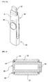
- Fig.2 is an exploded, perspective view of a flash memory apparatus having a single body type rotary cover of the present invention
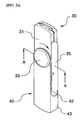
- Fig.3a and Fig.3b are perspective views showing keeping and usage status for a flash memory apparatus having a single body type rotary cover according to a preferred embodiment of the present invention
- Fig.4 is a schematic cross-sectional view for the portion, taken along line A-A of Fig.3a.
- the flash memory apparatus having a single body type rotary cover of the present invention includes a flash memory main body 30 and a cover 40 integrally joined to the flash memory main body 30.
- a case 31 of such flash memory main body 30 is of a rectangular shape whose width is wider than its thickness.
- the cover 40 has a cavity in its inside and is of a shape whose width is wider than its thickness, namely ' ⁇ ' shape, when seen from lateral side, having an opened terminal and a closed terminal.
- Such cover 40 has, in its opened terminal, a circular hinge hole 41 for receiving the hinge protuberance 33 formed on the flash memory main body 30.
- a hooking groove 34 is preferably formed on the lower periphery of the hinge protuberance 33 and a hooking threshold 45 hooked on the hooking groove 34, is preferably formed on a rim confining the hinge hole 41 in order to prevent the hinge hole 41 from being easily detached from the hinge protuberance 33 upon joining of the hinge hole 41 and the hinge protuberance 33.
- the function of the closely joining protuberance 35 formed on the flash memory main body 30, could be realized on an appropriate position in a front or a rear side. In that case, position of the fixing groove 42 formed on the cover 40 will be changed correspondingly.
- the hinge protuberance could be formed on the cover and the hinge hole could be formed on the flash memory main body.
- the hinge protuberance could be formed on only one side between the front and the rear sides of the case, and also, only one hinge hole for receiving the hinge protuberance could be provided to the cover.
Abstract
Description
Claims (4)
- A flash memory apparatus having a single body type rotary cover comprising:a flash memory main body including a rectangular shaped case within which a memory element is mounted, an USB (Universal Serial Bus) terminal piece electrically connected with the memory element and installed at a front end of the case in a projecting manner, and a hinge protuberance formed on at least one side among its front side and its back side; anda pair of parallel plate members facing each other with an interval corresponding to the thickness of the case, and whose front end is opened, whose terminal is closed and both lateral sides of which are opened; in which the parallel plate members have a cover on which a hinge hole joined to the hinge protuberance, for pivoting on a shaft, is formed, so that the cover is rotated with respect to the flash memory main body, whereby the USB terminal piece is received in an inner space of the cover or exposed to the outside.
- The apparatus according to claim 1, wherein a reception maintaining means is formed on the flash memory main body and the cover so that a status that the USB terminal piece is received in an inner space of the cover, is maintained.
- The apparatus according to claim 2, wherein the reception maintaining means includes a fixing groove formed by partially closing one side among both opened lateral sides of the cover, and a closely joining protuberance formed on one lateral side of the case, for being inserted into the fixing groove in a forcibly fitting manner when the USB terminal piece is received in an inner space of the cover.
- The apparatus as in any of the preceding claims, wherein a hooking groove is formed on a lower periphery of the hinge protuberance, and a hooking threshold for being hooked on the hooking groove upon joining of the hinge protuberance and the hinge hole, is formed on a lower portion of a rim confining the hinge hole.
Applications Claiming Priority (2)
| Application Number | Priority Date | Filing Date | Title |
|---|---|---|---|
| KR2020020016582U KR200286123Y1 (en) | 2002-05-30 | 2002-05-30 | flash memory apparatus with single body type rotary cover |
| KR2002016582 | 2002-05-30 |
Publications (3)
| Publication Number | Publication Date |
|---|---|
| EP1367497A2 true EP1367497A2 (en) | 2003-12-03 |
| EP1367497A3 EP1367497A3 (en) | 2006-03-15 |
| EP1367497B1 EP1367497B1 (en) | 2007-05-23 |
Family
ID=30439275
Family Applications (1)
| Application Number | Title | Priority Date | Filing Date |
|---|---|---|---|
| EP03001619A Expired - Lifetime EP1367497B1 (en) | 2002-05-30 | 2003-01-24 | Flash memory apparatus having single body type rotary cover |
Country Status (7)
| Country | Link |
|---|---|
| US (1) | US6926544B2 (en) |
| EP (1) | EP1367497B1 (en) |
| JP (1) | JP3694296B2 (en) |
| KR (1) | KR200286123Y1 (en) |
| CN (2) | CN1331379C (en) |
| AT (1) | ATE363101T1 (en) |
| DE (1) | DE60313915T2 (en) |
Cited By (8)
| Publication number | Priority date | Publication date | Assignee | Title |
|---|---|---|---|---|
| EP1719057A1 (en) * | 2004-02-27 | 2006-11-08 | Imation Corp. | Memory card compatible with device connector and host connector standards |
| EP1874015A2 (en) * | 2006-06-28 | 2008-01-02 | Samsung Electronics Co., Ltd. | External device for a portable terminal |
| WO2008066959A1 (en) * | 2006-11-28 | 2008-06-05 | Sony Ericsson Mobile Communications Ab | Electronic device accessory |
| WO2008144156A2 (en) * | 2007-05-16 | 2008-11-27 | Micron Technology, Inc. | Memory module having a cover pivotally coupled thereto |
| WO2009056318A1 (en) * | 2007-11-02 | 2009-05-07 | Giesecke & Devrient Gmbh | Protective device for a portable data carrier |
| WO2009088415A1 (en) * | 2008-01-07 | 2009-07-16 | Sony Ericsson Mobile Communications Ab | Usb modem devices with a flip antenna and a retractable usb connector |
| EP2071908A3 (en) * | 2007-12-11 | 2010-02-03 | Option | Peripheral telecommunications device having movable cover with integrated antenna |
| CN109146045A (en) * | 2018-09-05 | 2019-01-04 | 河南省云乐科技有限公司 | A kind of Novel ring USB flash disk |
Families Citing this family (73)
| Publication number | Priority date | Publication date | Assignee | Title |
|---|---|---|---|---|
| US6384117B1 (en) * | 1997-07-11 | 2002-05-07 | Bridgestone Corporation | Processability of silica-filled rubber stocks |
| US7740493B2 (en) * | 2004-02-26 | 2010-06-22 | Supertalent Electronics, Inc. | Universal serial bus (USB) flash drive housing a slim USB device and having swivel cap functionalities allowing for two locking positions |
| US7872871B2 (en) | 2000-01-06 | 2011-01-18 | Super Talent Electronics, Inc. | Molding methods to manufacture single-chip chip-on-board USB device |
| US7744387B2 (en) * | 1999-08-04 | 2010-06-29 | Super Talent Electronics, Inc. | Multi-level cell (MLC) rotate flash memory device |
| US8102662B2 (en) | 2007-07-05 | 2012-01-24 | Super Talent Electronics, Inc. | USB package with bistable sliding mechanism |
| US8625270B2 (en) | 1999-08-04 | 2014-01-07 | Super Talent Technology, Corp. | USB flash drive with deploying and retracting functionalities using retractable cover/cap |
| US7257714B1 (en) * | 1999-10-19 | 2007-08-14 | Super Talent Electronics, Inc. | Electronic data storage medium with fingerprint verification capability |
| US7466556B2 (en) * | 1999-08-04 | 2008-12-16 | Super Talent Electronics, Inc. | Single chip USB packages with swivel cover |
| US20040017911A1 (en) * | 2002-04-29 | 2004-01-29 | Nattkemper Dieter H. | Line powered network element |
| US7599484B2 (en) * | 2002-04-29 | 2009-10-06 | Adc Dsl Systems, Inc. | Element management system for managing line-powered network elements |
| US7454012B2 (en) * | 2002-04-29 | 2008-11-18 | Adc Dsl Systems, Inc. | Managing power in a line powered network element |
| KR20040023292A (en) * | 2002-09-11 | 2004-03-18 | 주식회사 새움테크 | Portable data storage for USB-port |
| TW555047U (en) * | 2002-10-28 | 2003-09-21 | Walton Advanced Eng Inc | Thin type USB personal disc |
| KR100479348B1 (en) * | 2002-11-08 | 2005-03-31 | 한국전자통신연구원 | Portable usb storage device |
| KR100560645B1 (en) * | 2002-12-17 | 2006-03-16 | 삼성전자주식회사 | USB flash memory device displaying memory using information |
| TW590146U (en) | 2003-05-14 | 2004-06-01 | Sinox Co Ltd | Padlock structure with hook locking and opening |
| US6932629B2 (en) * | 2003-11-05 | 2005-08-23 | Kabushiki Kaisha Toshiba | Device with USB terminal |
| US8998620B2 (en) * | 2003-12-02 | 2015-04-07 | Super Talent Technology, Corp. | Molding method for COB-EUSB devices and metal housing package |
| US8102657B2 (en) | 2003-12-02 | 2012-01-24 | Super Talent Electronics, Inc. | Single shot molding method for COB USB/EUSB devices with contact pad ribs |
| US20050185438A1 (en) * | 2004-01-07 | 2005-08-25 | Wei Ching | Low profile removable memory module |
| US7815469B1 (en) | 2004-02-12 | 2010-10-19 | Super Talent Electronics, Inc. | Dual-personality extended USB plugs and receptacles using with PCBA and cable assembly |
| KR100606832B1 (en) * | 2004-01-31 | 2006-08-01 | 엘지전자 주식회사 | Mobile phone having a large number of communication ports |
| TWI262373B (en) * | 2004-06-30 | 2006-09-21 | Apacer Technology Inc | Portable disk drive with a protective body |
| CN100351735C (en) * | 2004-08-06 | 2007-11-28 | 宇瞻科技股份有限公司 | Cover body and USB memory combination device |
| JP4698185B2 (en) * | 2004-09-02 | 2011-06-08 | 京セラ株式会社 | Information equipment card |
| US8353184B2 (en) | 2005-01-21 | 2013-01-15 | Sinox Company Ltd. | Tamper indicating padlock |
| CN2785316Y (en) * | 2005-03-18 | 2006-05-31 | 富士康(昆山)电脑接插件有限公司 | Quickflashing memory and its USB interface protecting cover |
| CN1841574B (en) * | 2005-03-31 | 2010-12-22 | 台均科技(深圳)有限公司 | Signal transmission line with audio and USB interface |
| CN2792095Y (en) * | 2005-04-14 | 2006-06-28 | 富士康(昆山)电脑接插件有限公司 | Mobile storage device |
| CN100573415C (en) * | 2005-06-10 | 2009-12-23 | 鸿富锦精密工业(深圳)有限公司 | Heat sink device for electronic equipment and method |
| CN2822109Y (en) * | 2005-07-15 | 2006-09-27 | 富士康(昆山)电脑接插件有限公司 | USB storage device and its connector protective cover |
| US20070048470A1 (en) * | 2005-08-16 | 2007-03-01 | Apple Computer, Inc. | Housing of an electronic device formed by doubleshot injection molding |
| KR100678135B1 (en) * | 2005-09-06 | 2007-02-02 | 삼성전자주식회사 | Mobile phone |
| US7549875B2 (en) | 2005-09-16 | 2009-06-23 | Imation Corp. | Swivel cap for flash memory device |
| TWI292006B (en) * | 2006-01-05 | 2008-01-01 | Sinox Co Ltd | Lock box |
| US7473112B2 (en) * | 2006-07-07 | 2009-01-06 | Hon Hai Precision Ind. Co., Ltd. | Flash memory device with elastic member |
| US7500858B2 (en) * | 2006-07-27 | 2009-03-10 | Micron Technology, Inc. | Portable electronic device with built-in terminal cover structure |
| KR100819459B1 (en) | 2006-10-18 | 2008-04-04 | 황보의 | Memory storage device |
| KR100773864B1 (en) | 2006-10-27 | 2007-11-09 | 황보의 | Memory storage device |
| BRPI0612528A2 (en) * | 2006-12-21 | 2010-11-23 | Trek 2000 Int Ltd | portable data storage device with connector retraction |
| US7568942B1 (en) * | 2007-02-07 | 2009-08-04 | Michael G. Lannon | Sleeve and coupler for electronic device |
| US7648374B2 (en) * | 2007-02-14 | 2010-01-19 | Koskondy Ronald L | USB device insulation sheath and method of insulating a USB device |
| KR100857037B1 (en) | 2007-03-06 | 2008-09-08 | 한국소아마비협회 | Exterior type usb equipment |
| TWI329913B (en) * | 2007-03-07 | 2010-09-01 | Asustek Comp Inc | Memory disk |
| US8102658B2 (en) | 2007-07-05 | 2012-01-24 | Super Talent Electronics, Inc. | Micro-SD to secure digital adaptor card and manufacturing method |
| KR100937380B1 (en) | 2007-10-04 | 2010-01-20 | 배정식 | Portable memory device |
| US8500467B2 (en) * | 2007-10-30 | 2013-08-06 | Super Talent Electronics, Inc. | Flash drive with swivel cover |
| KR101450777B1 (en) * | 2007-12-20 | 2014-10-14 | 삼성전자주식회사 | Rotary protection cover and portable communication terminal having the same |
| US20090212939A1 (en) * | 2008-02-21 | 2009-08-27 | Richmond Robert C | Dockable wireless remote control |
| KR200448824Y1 (en) * | 2008-03-21 | 2010-05-26 | 주식회사 셀픽 | Portable data storing device |
| CN201333302Y (en) * | 2008-04-28 | 2009-10-28 | 基内特兴业有限公司 | Information carrying device |
| KR100950587B1 (en) | 2008-11-14 | 2010-04-01 | (주)엠포유 | Usb memory apparatus of rotation type |
| CN101754604A (en) * | 2008-12-16 | 2010-06-23 | 威刚科技(苏州)有限公司 | Electrical storage device |
| CN101751975A (en) * | 2008-12-16 | 2010-06-23 | 威刚科技(苏州)有限公司 | Multi-angle positioning electronic storage device |
| TW201036512A (en) * | 2009-03-20 | 2010-10-01 | Walton Advanced Eng Inc | Adhesion-type memory device |
| US8246362B2 (en) * | 2009-05-27 | 2012-08-21 | Pny Technologies, Inc. | Computer peripheral device with a pin exerting a force to extend or retract a connector |
| CN201498751U (en) * | 2009-06-04 | 2010-06-02 | 富士康(昆山)电脑接插件有限公司 | Connector component |
| CN101931154B (en) * | 2009-06-26 | 2014-01-22 | 鸿富锦精密工业(深圳)有限公司 | Universal serial bus device |
| US7740495B1 (en) * | 2009-07-10 | 2010-06-22 | Yu-Nan Lo | Portable storage device |
| TW201103657A (en) * | 2009-07-20 | 2011-02-01 | Ho E Screw & Hardware Co Ltd | Forming method of single-sided tenon of metal sheet and flash drive having single-sided tenon of metal sheet |
| USD652046S1 (en) * | 2010-07-16 | 2012-01-10 | Pny Technologies, Inc. | USB drive with a label |
| US8388361B2 (en) | 2010-07-19 | 2013-03-05 | Pny Technologies, Inc. | Portable storage device with retractable connector |
| US8351195B2 (en) * | 2011-02-10 | 2013-01-08 | Microlan Integration, Inc. | Multifunctional universal serial bus flash drive organizer |
| US8974238B2 (en) * | 2011-06-20 | 2015-03-10 | Kingston Technology Corp. | Flip-covered portable memory storage device |
| USD673963S1 (en) | 2011-10-19 | 2013-01-08 | MIMOCO, Inc. | USB drive |
| USD673962S1 (en) | 2011-10-24 | 2013-01-08 | MIMOCO, Inc. | USB drive and card reader with body |
| US8811006B2 (en) * | 2012-04-06 | 2014-08-19 | Ho E Screw & Hardware Co., Ltd. | USB memory stick with a hinged safety hook |
| KR101307076B1 (en) * | 2013-04-04 | 2013-09-11 | 이진우 | Memory apparatus having different port |
| TWM497330U (en) * | 2014-10-01 | 2015-03-11 | Ho E Co Ltd | Flash drive having combined type protective lid |
| TWM497329U (en) * | 2014-10-01 | 2015-03-11 | Ho E Co Ltd | Flash drive with deflection opening/closing protection cover |
| CN104955298A (en) * | 2015-07-06 | 2015-09-30 | 岳文智 | Shock-resistant USB flash disk |
| TWM514089U (en) * | 2015-07-28 | 2015-12-11 | Hoey Co Ltd | Flash disk composite layer protection cover |
| USD991198S1 (en) * | 2022-09-30 | 2023-07-04 | Lefei Du | Lamp string controller |
Citations (2)
| Publication number | Priority date | Publication date | Assignee | Title |
|---|---|---|---|---|
| US4779950A (en) * | 1984-04-03 | 1988-10-25 | Thomas & Betts Corporation | Connection apparatus for optical fibers |
| EP1100000A2 (en) * | 1999-11-14 | 2001-05-16 | Guoshun c/o Netac Technology Co. Ltd. Deng | Electronic flash memory external storage method and device |
Family Cites Families (5)
| Publication number | Priority date | Publication date | Assignee | Title |
|---|---|---|---|---|
| US5816824A (en) * | 1995-08-16 | 1998-10-06 | White; James E. | Holder for a vehicle electrical connection component |
| JP3163967B2 (en) * | 1995-10-19 | 2001-05-08 | 住友電装株式会社 | Electromagnetic coupling device for charging electric vehicles |
| JP2940551B1 (en) * | 1998-09-21 | 1999-08-25 | 日本電気株式会社 | Opening and closing structure of the connector storage lid of information equipment |
| CN1152307C (en) * | 2000-02-23 | 2004-06-02 | 邓国顺 | Method and device for implementing fully electronic flash storage |
| CN2479547Y (en) * | 2001-01-21 | 2002-02-27 | 北京飞天诚信科技有限公司 | Micro memory with USB plug |
-
2002
- 2002-05-30 KR KR2020020016582U patent/KR200286123Y1/en not_active IP Right Cessation
-
2003
- 2003-01-17 US US10/346,105 patent/US6926544B2/en not_active Expired - Lifetime
- 2003-01-22 JP JP2003013787A patent/JP3694296B2/en not_active Expired - Lifetime
- 2003-01-24 AT AT03001619T patent/ATE363101T1/en not_active IP Right Cessation
- 2003-01-24 EP EP03001619A patent/EP1367497B1/en not_active Expired - Lifetime
- 2003-01-24 DE DE60313915T patent/DE60313915T2/en not_active Expired - Lifetime
- 2003-02-18 CN CNB2005100095233A patent/CN1331379C/en not_active Expired - Lifetime
- 2003-02-18 CN CNB031037631A patent/CN1231842C/en not_active Expired - Lifetime
Patent Citations (2)
| Publication number | Priority date | Publication date | Assignee | Title |
|---|---|---|---|---|
| US4779950A (en) * | 1984-04-03 | 1988-10-25 | Thomas & Betts Corporation | Connection apparatus for optical fibers |
| EP1100000A2 (en) * | 1999-11-14 | 2001-05-16 | Guoshun c/o Netac Technology Co. Ltd. Deng | Electronic flash memory external storage method and device |
Cited By (14)
| Publication number | Priority date | Publication date | Assignee | Title |
|---|---|---|---|---|
| EP1719057A1 (en) * | 2004-02-27 | 2006-11-08 | Imation Corp. | Memory card compatible with device connector and host connector standards |
| EP1874015A2 (en) * | 2006-06-28 | 2008-01-02 | Samsung Electronics Co., Ltd. | External device for a portable terminal |
| EP1874015A3 (en) * | 2006-06-28 | 2012-04-18 | Samsung Electronics Co., Ltd. | External device for a portable terminal |
| WO2008066959A1 (en) * | 2006-11-28 | 2008-06-05 | Sony Ericsson Mobile Communications Ab | Electronic device accessory |
| US7991433B2 (en) | 2006-11-28 | 2011-08-02 | Sony Ericsson Mobile Communications Ab | Electronic device accessory |
| US7815464B2 (en) | 2007-05-16 | 2010-10-19 | Micron Technology, Inc. | Storage device having a memory module, cover, and light-transmission elements |
| US7699630B2 (en) | 2007-05-16 | 2010-04-20 | Micron Technology, Inc. | Memory module having a cover pivotally coupled thereto |
| WO2008144156A3 (en) * | 2007-05-16 | 2009-02-19 | Micron Technology Inc | Memory module having a cover pivotally coupled thereto |
| WO2008144156A2 (en) * | 2007-05-16 | 2008-11-27 | Micron Technology, Inc. | Memory module having a cover pivotally coupled thereto |
| WO2009056318A1 (en) * | 2007-11-02 | 2009-05-07 | Giesecke & Devrient Gmbh | Protective device for a portable data carrier |
| EP2071908A3 (en) * | 2007-12-11 | 2010-02-03 | Option | Peripheral telecommunications device having movable cover with integrated antenna |
| US8354966B2 (en) | 2007-12-11 | 2013-01-15 | Option | Peripheral telecommunications device having movable cover with integrated antenna |
| WO2009088415A1 (en) * | 2008-01-07 | 2009-07-16 | Sony Ericsson Mobile Communications Ab | Usb modem devices with a flip antenna and a retractable usb connector |
| CN109146045A (en) * | 2018-09-05 | 2019-01-04 | 河南省云乐科技有限公司 | A kind of Novel ring USB flash disk |
Also Published As
| Publication number | Publication date |
|---|---|
| US6926544B2 (en) | 2005-08-09 |
| JP3694296B2 (en) | 2005-09-14 |
| ATE363101T1 (en) | 2007-06-15 |
| US20030223286A1 (en) | 2003-12-04 |
| EP1367497B1 (en) | 2007-05-23 |
| CN1231842C (en) | 2005-12-14 |
| JP2004005407A (en) | 2004-01-08 |
| CN1655665A (en) | 2005-08-17 |
| DE60313915D1 (en) | 2007-07-05 |
| KR200286123Y1 (en) | 2002-08-22 |
| CN1331379C (en) | 2007-08-08 |
| DE60313915T2 (en) | 2008-01-31 |
| CN1461998A (en) | 2003-12-17 |
| EP1367497A3 (en) | 2006-03-15 |
Similar Documents
| Publication | Publication Date | Title |
|---|---|---|
| EP1367497B1 (en) | Flash memory apparatus having single body type rotary cover | |
| US20060079133A1 (en) | Socket for trans-flash memory card | |
| US20080125171A1 (en) | Portable terminal with protrusion type mic module | |
| US5804332A (en) | Battery accommodating chamber structure | |
| US7909250B2 (en) | Memory card slot door unit and digital mobile apparatus having the same | |
| US20070243732A1 (en) | Rotatable memory card with improved locking mechanism | |
| US20070275759A1 (en) | Memory card removal guard | |
| US8995135B2 (en) | Electronic device and a casing used therefor | |
| JPH1131025A (en) | Pc card slot | |
| KR100659930B1 (en) | Electrical connector with shutter member | |
| JP2004328596A (en) | Mobile terminal | |
| KR100686047B1 (en) | A Receptacle Connecting Part For Mobile Handset | |
| JPH11273780A (en) | Mounting structure of connector protection cover | |
| KR20070021374A (en) | Mobile communication terminal including external card device | |
| KR101076510B1 (en) | Mobile terminal | |
| KR20080062670A (en) | Sim card gender | |
| JP3897485B2 (en) | Video camera | |
| KR100764786B1 (en) | Mobile communication terminal | |
| KR101048181B1 (en) | Battery cover device | |
| KR100613060B1 (en) | Mobile communication terminal having pivotal in and out type earphone connector | |
| JP2004063255A (en) | Slot connector | |
| JP3678671B2 (en) | Cover storage structure for mobile phone radio | |
| US20020039250A1 (en) | Recording apparatus enabling replacement of disk cartridge | |
| JP2006114300A (en) | Small electronic equipment | |
| JPH07282204A (en) | Shutter mechanism for card module |
Legal Events
| Date | Code | Title | Description |
|---|---|---|---|
| PUAI | Public reference made under article 153(3) epc to a published international application that has entered the european phase |
Free format text: ORIGINAL CODE: 0009012 |
|
| 17P | Request for examination filed |
Effective date: 20030124 |
|
| AK | Designated contracting states |
Kind code of ref document: A2 Designated state(s): AT BE BG CH CY CZ DE DK EE ES FI FR GB GR HU IE IT LI LU MC NL PT SE SI SK TR |
|
| AX | Request for extension of the european patent |
Extension state: AL LT LV MK RO |
|
| PUAL | Search report despatched |
Free format text: ORIGINAL CODE: 0009013 |
|
| AK | Designated contracting states |
Kind code of ref document: A3 Designated state(s): AT BE BG CH CY CZ DE DK EE ES FI FR GB GR HU IE IT LI LU MC NL PT SE SI SK TR |
|
| AX | Request for extension of the european patent |
Extension state: AL LT LV MK RO |
|
| RIC1 | Information provided on ipc code assigned before grant |
Ipc: G11B 33/02 20060101ALI20060124BHEP Ipc: G06F 3/06 20060101ALI20060124BHEP Ipc: H01R 13/52 20060101ALI20060124BHEP Ipc: H01R 13/447 20060101ALI20060124BHEP Ipc: G06F 13/40 20060101AFI20030927BHEP |
|
| AKX | Designation fees paid |
Designated state(s): AT BE BG CH CY CZ DE DK EE ES FI FR GB GR HU IE IT LI LU MC NL PT SE SI SK TR |
|
| GRAP | Despatch of communication of intention to grant a patent |
Free format text: ORIGINAL CODE: EPIDOSNIGR1 |
|
| GRAS | Grant fee paid |
Free format text: ORIGINAL CODE: EPIDOSNIGR3 |
|
| GRAA | (expected) grant |
Free format text: ORIGINAL CODE: 0009210 |
|
| AK | Designated contracting states |
Kind code of ref document: B1 Designated state(s): AT BE BG CH CY CZ DE DK EE ES FI FR GB GR HU IE IT LI LU MC NL PT SE SI SK TR |
|
| PG25 | Lapsed in a contracting state [announced via postgrant information from national office to epo] |
Ref country code: FI Free format text: LAPSE BECAUSE OF FAILURE TO SUBMIT A TRANSLATION OF THE DESCRIPTION OR TO PAY THE FEE WITHIN THE PRESCRIBED TIME-LIMIT Effective date: 20070523 Ref country code: LI Free format text: LAPSE BECAUSE OF FAILURE TO SUBMIT A TRANSLATION OF THE DESCRIPTION OR TO PAY THE FEE WITHIN THE PRESCRIBED TIME-LIMIT Effective date: 20070523 Ref country code: CH Free format text: LAPSE BECAUSE OF FAILURE TO SUBMIT A TRANSLATION OF THE DESCRIPTION OR TO PAY THE FEE WITHIN THE PRESCRIBED TIME-LIMIT Effective date: 20070523 |
|
| REG | Reference to a national code |
Ref country code: GB Ref legal event code: FG4D |
|
| REG | Reference to a national code |
Ref country code: CH Ref legal event code: EP |
|
| REG | Reference to a national code |
Ref country code: IE Ref legal event code: FG4D |
|
| REF | Corresponds to: |
Ref document number: 60313915 Country of ref document: DE Date of ref document: 20070705 Kind code of ref document: P |
|
| PG25 | Lapsed in a contracting state [announced via postgrant information from national office to epo] |
Ref country code: SE Free format text: LAPSE BECAUSE OF FAILURE TO SUBMIT A TRANSLATION OF THE DESCRIPTION OR TO PAY THE FEE WITHIN THE PRESCRIBED TIME-LIMIT Effective date: 20070823 |
|
| PG25 | Lapsed in a contracting state [announced via postgrant information from national office to epo] |
Ref country code: ES Free format text: LAPSE BECAUSE OF FAILURE TO SUBMIT A TRANSLATION OF THE DESCRIPTION OR TO PAY THE FEE WITHIN THE PRESCRIBED TIME-LIMIT Effective date: 20070903 |
|
| ET | Fr: translation filed | ||
| NLV1 | Nl: lapsed or annulled due to failure to fulfill the requirements of art. 29p and 29m of the patents act | ||
| PG25 | Lapsed in a contracting state [announced via postgrant information from national office to epo] |
Ref country code: AT Free format text: LAPSE BECAUSE OF FAILURE TO SUBMIT A TRANSLATION OF THE DESCRIPTION OR TO PAY THE FEE WITHIN THE PRESCRIBED TIME-LIMIT Effective date: 20070523 |
|
| REG | Reference to a national code |
Ref country code: CH Ref legal event code: PL |
|
| PG25 | Lapsed in a contracting state [announced via postgrant information from national office to epo] |
Ref country code: BE Free format text: LAPSE BECAUSE OF FAILURE TO SUBMIT A TRANSLATION OF THE DESCRIPTION OR TO PAY THE FEE WITHIN THE PRESCRIBED TIME-LIMIT Effective date: 20070523 |
|
| PG25 | Lapsed in a contracting state [announced via postgrant information from national office to epo] |
Ref country code: DK Free format text: LAPSE BECAUSE OF FAILURE TO SUBMIT A TRANSLATION OF THE DESCRIPTION OR TO PAY THE FEE WITHIN THE PRESCRIBED TIME-LIMIT Effective date: 20070523 Ref country code: NL Free format text: LAPSE BECAUSE OF FAILURE TO SUBMIT A TRANSLATION OF THE DESCRIPTION OR TO PAY THE FEE WITHIN THE PRESCRIBED TIME-LIMIT Effective date: 20070523 Ref country code: CZ Free format text: LAPSE BECAUSE OF FAILURE TO SUBMIT A TRANSLATION OF THE DESCRIPTION OR TO PAY THE FEE WITHIN THE PRESCRIBED TIME-LIMIT Effective date: 20070523 Ref country code: PT Free format text: LAPSE BECAUSE OF FAILURE TO SUBMIT A TRANSLATION OF THE DESCRIPTION OR TO PAY THE FEE WITHIN THE PRESCRIBED TIME-LIMIT Effective date: 20071023 Ref country code: SI Free format text: LAPSE BECAUSE OF FAILURE TO SUBMIT A TRANSLATION OF THE DESCRIPTION OR TO PAY THE FEE WITHIN THE PRESCRIBED TIME-LIMIT Effective date: 20070523 Ref country code: BG Free format text: LAPSE BECAUSE OF FAILURE TO SUBMIT A TRANSLATION OF THE DESCRIPTION OR TO PAY THE FEE WITHIN THE PRESCRIBED TIME-LIMIT Effective date: 20070823 |
|
| PG25 | Lapsed in a contracting state [announced via postgrant information from national office to epo] |
Ref country code: SK Free format text: LAPSE BECAUSE OF FAILURE TO SUBMIT A TRANSLATION OF THE DESCRIPTION OR TO PAY THE FEE WITHIN THE PRESCRIBED TIME-LIMIT Effective date: 20070523 |
|
| PLBE | No opposition filed within time limit |
Free format text: ORIGINAL CODE: 0009261 |
|
| STAA | Information on the status of an ep patent application or granted ep patent |
Free format text: STATUS: NO OPPOSITION FILED WITHIN TIME LIMIT |
|
| 26N | No opposition filed |
Effective date: 20080226 |
|
| PG25 | Lapsed in a contracting state [announced via postgrant information from national office to epo] |
Ref country code: IT Free format text: LAPSE BECAUSE OF FAILURE TO SUBMIT A TRANSLATION OF THE DESCRIPTION OR TO PAY THE FEE WITHIN THE PRESCRIBED TIME-LIMIT Effective date: 20070523 Ref country code: GR Free format text: LAPSE BECAUSE OF FAILURE TO SUBMIT A TRANSLATION OF THE DESCRIPTION OR TO PAY THE FEE WITHIN THE PRESCRIBED TIME-LIMIT Effective date: 20070824 |
|
| PG25 | Lapsed in a contracting state [announced via postgrant information from national office to epo] |
Ref country code: MC Free format text: LAPSE BECAUSE OF NON-PAYMENT OF DUE FEES Effective date: 20080131 |
|
| PG25 | Lapsed in a contracting state [announced via postgrant information from national office to epo] |
Ref country code: EE Free format text: LAPSE BECAUSE OF FAILURE TO SUBMIT A TRANSLATION OF THE DESCRIPTION OR TO PAY THE FEE WITHIN THE PRESCRIBED TIME-LIMIT Effective date: 20070523 Ref country code: IE Free format text: LAPSE BECAUSE OF NON-PAYMENT OF DUE FEES Effective date: 20080124 |
|
| PG25 | Lapsed in a contracting state [announced via postgrant information from national office to epo] |
Ref country code: CY Free format text: LAPSE BECAUSE OF FAILURE TO SUBMIT A TRANSLATION OF THE DESCRIPTION OR TO PAY THE FEE WITHIN THE PRESCRIBED TIME-LIMIT Effective date: 20070523 |
|
| PG25 | Lapsed in a contracting state [announced via postgrant information from national office to epo] |
Ref country code: LU Free format text: LAPSE BECAUSE OF NON-PAYMENT OF DUE FEES Effective date: 20080124 Ref country code: HU Free format text: LAPSE BECAUSE OF FAILURE TO SUBMIT A TRANSLATION OF THE DESCRIPTION OR TO PAY THE FEE WITHIN THE PRESCRIBED TIME-LIMIT Effective date: 20071124 |
|
| PG25 | Lapsed in a contracting state [announced via postgrant information from national office to epo] |
Ref country code: TR Free format text: LAPSE BECAUSE OF FAILURE TO SUBMIT A TRANSLATION OF THE DESCRIPTION OR TO PAY THE FEE WITHIN THE PRESCRIBED TIME-LIMIT Effective date: 20070523 |
|
| REG | Reference to a national code |
Ref country code: DE Ref legal event code: R082 Ref document number: 60313915 Country of ref document: DE Representative=s name: DR. POEHNER UND KOLLEGEN, DE |
|
| REG | Reference to a national code |
Ref country code: GB Ref legal event code: 732E Free format text: REGISTERED BETWEEN 20120216 AND 20120222 |
|
| REG | Reference to a national code |
Ref country code: FR Ref legal event code: TP Owner name: LEEONIPL, KR Effective date: 20120307 |
|
| REG | Reference to a national code |
Ref country code: DE Ref legal event code: R082 Ref document number: 60313915 Country of ref document: DE Representative=s name: DR. POEHNER UND KOLLEGEN, DE Effective date: 20120313 Ref country code: DE Ref legal event code: R081 Ref document number: 60313915 Country of ref document: DE Owner name: CATR CO., LTD., KR Free format text: FORMER OWNER: HANA MICRON INC., ASAN-CITY, KR Effective date: 20120313 Ref country code: DE Ref legal event code: R082 Ref document number: 60313915 Country of ref document: DE Representative=s name: BARDEHLE PAGENBERG PARTNERSCHAFT MBB PATENTANW, DE Effective date: 20120313 Ref country code: DE Ref legal event code: R081 Ref document number: 60313915 Country of ref document: DE Owner name: CATR CO., LTD., YONGIN-SI, KR Free format text: FORMER OWNER: HANA MICRON INC., ASAN-CITY, KR Effective date: 20120313 Ref country code: DE Ref legal event code: R082 Ref document number: 60313915 Country of ref document: DE Representative=s name: BARDEHLE PAGENBERG PARTNERSCHAFT PATENTANWAELT, DE Effective date: 20120313 Ref country code: DE Ref legal event code: R081 Ref document number: 60313915 Country of ref document: DE Owner name: PAVO SOLUTIONS LLC, WILMINGTON, US Free format text: FORMER OWNER: HANA MICRON INC., ASAN-CITY, KR Effective date: 20120313 |
|
| REG | Reference to a national code |
Ref country code: DE Ref legal event code: R082 Ref document number: 60313915 Country of ref document: DE Representative=s name: DR. POEHNER UND KOLLEGEN, DE |
|
| REG | Reference to a national code |
Ref country code: GB Ref legal event code: 732E Free format text: REGISTERED BETWEEN 20121122 AND 20121128 |
|
| REG | Reference to a national code |
Ref country code: FR Ref legal event code: TP Owner name: CATR CO., LTD., KR Effective date: 20121128 |
|
| REG | Reference to a national code |
Ref country code: DE Ref legal event code: R082 Ref document number: 60313915 Country of ref document: DE Representative=s name: DR. POEHNER UND KOLLEGEN, DE Effective date: 20121214 Ref country code: DE Ref legal event code: R081 Ref document number: 60313915 Country of ref document: DE Owner name: CATR CO., LTD., KR Free format text: FORMER OWNER: LEEONIPL, SEOUL, KR Effective date: 20121214 Ref country code: DE Ref legal event code: R081 Ref document number: 60313915 Country of ref document: DE Owner name: CATR CO., LTD., YONGIN-SI, KR Free format text: FORMER OWNER: LEEONIPL, SEOUL, GURO-GU, KR Effective date: 20121214 Ref country code: DE Ref legal event code: R082 Ref document number: 60313915 Country of ref document: DE Representative=s name: BARDEHLE PAGENBERG PARTNERSCHAFT MBB PATENTANW, DE Effective date: 20121214 Ref country code: DE Ref legal event code: R082 Ref document number: 60313915 Country of ref document: DE Representative=s name: BARDEHLE PAGENBERG PARTNERSCHAFT PATENTANWAELT, DE Effective date: 20121214 Ref country code: DE Ref legal event code: R081 Ref document number: 60313915 Country of ref document: DE Owner name: PAVO SOLUTIONS LLC, WILMINGTON, US Free format text: FORMER OWNER: LEEONIPL, SEOUL, GURO-GU, KR Effective date: 20121214 |
|
| REG | Reference to a national code |
Ref country code: DE Ref legal event code: R082 Ref document number: 60313915 Country of ref document: DE Representative=s name: BARDEHLE PAGENBERG PARTNERSCHAFT MBB PATENTANW, DE Ref country code: DE Ref legal event code: R082 Ref document number: 60313915 Country of ref document: DE Representative=s name: BARDEHLE PAGENBERG PARTNERSCHAFT PATENTANWAELT, DE |
|
| REG | Reference to a national code |
Ref country code: DE Ref legal event code: R082 Ref document number: 60313915 Country of ref document: DE Representative=s name: BARDEHLE PAGENBERG PARTNERSCHAFT MBB PATENTANW, DE Ref country code: DE Ref legal event code: R081 Ref document number: 60313915 Country of ref document: DE Owner name: PAVO SOLUTIONS LLC, WILMINGTON, US Free format text: FORMER OWNER: CATR CO., LTD., YONGIN-SI, GYEONGGI-DO, KR |
|
| REG | Reference to a national code |
Ref country code: FR Ref legal event code: PLFP Year of fee payment: 14 |
|
| REG | Reference to a national code |
Ref country code: GB Ref legal event code: 732E Free format text: REGISTERED BETWEEN 20151126 AND 20151202 |
|
| REG | Reference to a national code |
Ref country code: FR Ref legal event code: TP Owner name: PAVO SOLUTIONS LLC, US Effective date: 20151203 |
|
| REG | Reference to a national code |
Ref country code: FR Ref legal event code: PLFP Year of fee payment: 15 |
|
| REG | Reference to a national code |
Ref country code: FR Ref legal event code: PLFP Year of fee payment: 16 |
|
| PGFP | Annual fee paid to national office [announced via postgrant information from national office to epo] |
Ref country code: GB Payment date: 20211220 Year of fee payment: 20 Ref country code: FR Payment date: 20211223 Year of fee payment: 20 |
|
| PGFP | Annual fee paid to national office [announced via postgrant information from national office to epo] |
Ref country code: DE Payment date: 20211220 Year of fee payment: 20 |
|
| REG | Reference to a national code |
Ref country code: DE Ref legal event code: R071 Ref document number: 60313915 Country of ref document: DE |
|
| REG | Reference to a national code |
Ref country code: GB Ref legal event code: PE20 Expiry date: 20230123 |
|
| PG25 | Lapsed in a contracting state [announced via postgrant information from national office to epo] |
Ref country code: GB Free format text: LAPSE BECAUSE OF EXPIRATION OF PROTECTION Effective date: 20230123 |