EP1371879A2 - Epicyclic gear - Google Patents
Epicyclic gear Download PDFInfo
- Publication number
- EP1371879A2 EP1371879A2 EP03011486A EP03011486A EP1371879A2 EP 1371879 A2 EP1371879 A2 EP 1371879A2 EP 03011486 A EP03011486 A EP 03011486A EP 03011486 A EP03011486 A EP 03011486A EP 1371879 A2 EP1371879 A2 EP 1371879A2
- Authority
- EP
- European Patent Office
- Prior art keywords
- projections
- planetary gear
- planet carrier
- wheels
- planetary
- Prior art date
- Legal status (The legal status is an assumption and is not a legal conclusion. Google has not performed a legal analysis and makes no representation as to the accuracy of the status listed.)
- Granted
Links
Images


Classifications
-
- F—MECHANICAL ENGINEERING; LIGHTING; HEATING; WEAPONS; BLASTING
- F16—ENGINEERING ELEMENTS AND UNITS; GENERAL MEASURES FOR PRODUCING AND MAINTAINING EFFECTIVE FUNCTIONING OF MACHINES OR INSTALLATIONS; THERMAL INSULATION IN GENERAL
- F16H—GEARING
- F16H57/00—General details of gearing
- F16H57/08—General details of gearing of gearings with members having orbital motion
- F16H57/082—Planet carriers
-
- F—MECHANICAL ENGINEERING; LIGHTING; HEATING; WEAPONS; BLASTING
- F16—ENGINEERING ELEMENTS AND UNITS; GENERAL MEASURES FOR PRODUCING AND MAINTAINING EFFECTIVE FUNCTIONING OF MACHINES OR INSTALLATIONS; THERMAL INSULATION IN GENERAL
- F16H—GEARING
- F16H57/00—General details of gearing
- F16H57/04—Features relating to lubrication or cooling or heating
- F16H57/0409—Features relating to lubrication or cooling or heating characterised by the problem to increase efficiency, e.g. by reducing splash losses
-
- F—MECHANICAL ENGINEERING; LIGHTING; HEATING; WEAPONS; BLASTING
- F16—ENGINEERING ELEMENTS AND UNITS; GENERAL MEASURES FOR PRODUCING AND MAINTAINING EFFECTIVE FUNCTIONING OF MACHINES OR INSTALLATIONS; THERMAL INSULATION IN GENERAL
- F16H—GEARING
- F16H57/00—General details of gearing
- F16H57/04—Features relating to lubrication or cooling or heating
- F16H57/042—Guidance of lubricant
- F16H57/0427—Guidance of lubricant on rotary parts, e.g. using baffles for collecting lubricant by centrifugal force
-
- F—MECHANICAL ENGINEERING; LIGHTING; HEATING; WEAPONS; BLASTING
- F16—ENGINEERING ELEMENTS AND UNITS; GENERAL MEASURES FOR PRODUCING AND MAINTAINING EFFECTIVE FUNCTIONING OF MACHINES OR INSTALLATIONS; THERMAL INSULATION IN GENERAL
- F16H—GEARING
- F16H57/00—General details of gearing
- F16H57/04—Features relating to lubrication or cooling or heating
- F16H57/048—Type of gearings to be lubricated, cooled or heated
- F16H57/0482—Gearings with gears having orbital motion
Definitions
- the invention relates to a planetary gear that has a sun gear, a plurality of planetary gears, each on one associated axis rotatably mounted on a planet carrier are, and optionally one surrounding the planetary gears Ring gear or housing contains.
- Planetary gear in particular friction and gear planetary gear are used in many areas of the drive and Abtriebstechnik used, especially where the Realization of a high translation and a compact Construction is required, such. B. in automotive engineering. there it is desirable with such planetary gears one To achieve the highest possible efficiency.
- planetary gear generally have a connected to a drive shaft Sun wheel on which is guided by a planet carrier Scroll planet gears, with the planet gears in different number evenly around the sun gear are arranged.
- a ring gear is arranged around the planets which support the planetary gears.
- the planet wheels are each rotatably mounted on axles, which are fixed to the Planet carrier are connected. The execution of a Planet carrier can be single-minded, i.
- the planet axes be recorded on one side of the planet carrier, or multi-pronged, i. the planetary axes are at several points be taken by the planet carrier carried out.
- Planet pin or planet pins used.
- Such Execution of a planetary gear unit with single-arm Planet carrier is disclosed in WO 01/35004 A1.
- This type of Reibrad- or gear arrangement resulting in a Variety of torque and speed transmissions. So can For example, the output via the ring gear or over the Planet carrier done.
- Other possibilities and variations with regard to the drive and output options Planetary gears are known and used for example in "Dubbel, paperback for mechanical engineering" described.
- Planetary gearboxes are among other things as Achsendgetriebe used in agricultural vehicles, e.g. also at John Deere tractors.
- the exact execution of a Axle transmission for the 6000 series of a John Deere tractor is in "Technical Manual 4552, Part 3, Section 256-20C1" shown.
- the final gear essentially consists of this from a final gear housing, the planetary gear and a Wheel axle.
- the planetary gear is driven by a drive axle of the Drivetrain of the tractor driven, which is the sun gear representing the planetary gear.
- the object underlying the invention is seen therein to specify a planetary gear of the type mentioned, by which the aforementioned problems are overcome.
- an efficiency-optimized planetary gear should be proposed, in which the rotation of the Planet carrier and the planet resulting churning losses reduced and foaming of the transmission oil is reduced.
- the by the circulation of the wheels to the Transmission oil emitted heat energy can be reduced.
- the planet carrier axially extending, free-standing projections provided by the Gaps between adjacent planetary gears, the sun gear and optionally the ring gear or housing are essentially filled in such a way that no Contact between the projections and the wheels comes.
- the trained Projections on the planet carrier provide a guided, shallow immersion of the planets in the gear oil bath and prevent the planet from reaching the surface of the planet Gear oil bath "open" and the gear oil bath lather. This will optimize the efficiency of the Planetary gear achieved by chute loss reduction.
- the turbulence of the transmission oil is significantly reduced and this essentially only on specifiable tracks in moves the spaces, less heat energy is generated, so that the oil temperatures are lower.
- the projections according to the invention are both in Friction gears as well as gear planetary gears or also in other planetary gearboxes where on planetary axles stored planets orbiting a center point, can be used.
- the Projections can be made of a relatively soft or low-strength material exist because the projections freestanding are formed and no load-bearing or force-transmitting Have function.
- a Projection essentially the contour and the volume of a Interspace on, such that between the projection and the The projection surrounding wheels is substantially constant Spacer joints are formed.
- the distance joints are like that Measure that along the cylindrically curved envelope surface of each wheel (sun gear, planetary gear and ring gear) preferably as small and constant distance to the Surface of the projections is made, the Surfaces of the projections also cylindrically curved Have enveloping surfaces and the envelope surfaces of the wheels correspond, so that the contour of the projections in the Essentially conforming to the geometry of the wheels.
- the smaller the distance joints the greater filled volumes of the spaces and the lower the Splash losses in the planetary gear.
- an embodiment of the planetary gear may be appropriate with larger distance joints, i. that too at not widely filled spaces one Reduction of churning losses and thus an optimization of the Transmission efficiency occurs.
- the planet carrier and the projections of a part manufactured, for example cast in one piece are manufactured, for example cast in one piece.
- the one-piece training is to the advantage that a Assembly of the projections on the planet carrier deleted and the Manufacturing costs can be reduced.
- the Projections formed separately and on the planet carrier are attached.
- the attachment of the projections to the Planet carrier takes place for example by Fittings, dowel pins, rivets, welds or others Links.
- the advantage of this solution lies in particular in that the planet carrier and the protrusions are out different materials can exist and for the Protrusions used less solid and lighter material can be.
- one-wheeled planet carrier is in terms of the planet carrier opposite end faces of the Projections provided an end plate, which the Protuberances and planetary gears covers.
- the cover of the Planet wheels through a cover plate causes a additional optimization of the efficiency, since the Self-rotation of the planets in this way only in the reduced Dimensions on the transmission oil bath affects.
- the end plate will preferably formed separately and to the projections or attached to the planet carrier. The attachment of the End plate to the projections or to the planet carrier takes place for example by screwing, Dowel pins, rivets, welds or other connections.
- the End plate and the projections preferably in one piece trained and fastened together to the planet carrier, whereby fastening measures for the end plate can be saved.
- At least one of the wheels facing surface of the projections and possibly formed the end plate profiled are preferably in the surface introduced the projections, such that a flow-optimized interaction between the surface and caused the transmission oil.
- the flow marks are preferably on the cylindrically curved outer surfaces introduced the projections and preferably run in Direction of rotation of the wheels.
- the introduction other flow optimizing profilings conceivable, such e.g. a scale pattern or the like.
- the projections and optionally also the end plate especially if separate Training, preferably made of a material with less Strength and / or density. Because the projections as well possibly also the end plate no significant It is possible to transmit forces and / or moments Components preferably made of a light and relatively soft Produce material. So the projections can for example, aluminum, heat resistant plastic (e.g. Polyamide) or carbon fiber exist. Is advantageous in that such materials have a very low density own and thus also no significant, additional Masses need to be moved.
- the Projections may be formed as a hollow body. This can also a weight optimization when using such Projections are achieved.
- the hollow bodies are preferably closed, so that no transmission oil can penetrate.
- Fig. 1 and Fig. 2 is a schematically Gear planetary gear 10 shown in the Essentially a drive axle or a sun gear 12, a connected to a driven axle, not shown Planet carrier 14, planet gears 16, 18, 20 and one with a not shown housing fixedly connected ring gear 22 includes.
- the teeth of the wheels 12, 16, 18, 20, 22 is in the figures not shown in detail. With the planetary gear it could also be a Reibradplanetengetriebe.
- the planet carrier 14 contains evenly on its circumference distributed, axially extending planetary axes or Planet pins 24, 26, 28, on which the planet gears 16, 18, 20 are rotatably mounted, wherein the storage and an axial Fixation of the planetary gears 16, 18, 20 on the planetary pin 24, 26, 28 is not shown in detail. Furthermore contains the planet carrier 14 evenly distributed on its circumference, axially over the entire width of the planet gears 16, 18, 20 extending projections 30, 32, 34 fixed to the Planet carrier 14 are connected.
- the planets 16, 18, 20 are connected to the sun gear 12 and the Ring gear 22 in tooth engagement, wherein the planetary gears 16, 18, 20 the sun gear 12 and rotate on the inside of the Ring wheel 22 roll while the planet pins 24, 26, 28th to move the sun gear 12.
- the planet carrier 14 in Rotation brought.
- each projection 30, 32, 34 i. the contour and volume of each projection 30, 32, 34 preferably corresponds substantially to the contour and the Volume of itself between planet gears 16, 18, 20, sun gear 12 and ring gear 22 resulting gap.
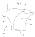
- An appropriate one Projection 30 is representative of all projections in FIG. 3 30, 32, 34, shown in detail.
- the projections 30, 32, 34 thus contain four cylindrically curved surfaces 36, 38, 40, 42 and two planar end face 44, 46.
- the radii of curvature of cylindrically curved surfaces 36, 38, 40, 42 are connected to the Radii of curvature of the respective wheels 12, 16, 18, 20, 22 customized.
- the centers of curvature of the curved surfaces 36, 38, 40, 42 coincide with the axes of rotation of the respective wheels 12, 16, 18, 20, 22 together.
- the radius of the surface 36 corresponds substantially to the inner radius of the ring gear 22
- the radius of the surfaces 38 and 40 is substantially equal the outer radius of the planet gears 16, 18, 20
- the radius the surface 42 substantially corresponds to the outer radius of the Sun wheel 12.
- the size of the projections 30, 32, 34 is here such that between the wheels 12, 16, 18, 20, 22 and the cylindrically curved surfaces 36, 38, 40, 42 of the Projections 30, 32, 34 are substantially constant and equal wide clearance gaps 48, 50, 52, 54 result, so that the Protrusions 30, 32, 34 without contact with the wheels 12, 16, 18, 20, 22 are arranged free-standing on the planet carrier 14, wherein the width of the spacer joints 48, 50, 52, 54 at a Vehicle transmission is preferably a few millimeters.
- Fig. 4 shows an alternative to Fig. 3 embodiment a projection according to the invention.
- the flow marks are in one uniform axial distance along the surfaces 36, 38, 40, 42 distributed and have a width of a few, preferably 3-5 millimeters.
- Fig. 5 shows an alternative embodiment of a planetary gear according to the invention, in which case the in Figs. 1 to 3 illustrated planetary gear in addition to a End plate 72 is provided.
- the end plate 72 is cylindrically shaped and closes in the radial direction flush with the projections 30, 32, 34 from.
- the end plate 72 includes a central bore 74, the diameter of something greater than the diameter of the sun gear 12, so that the Sonnerad 12 can be passed through the hole without a contact between end plate 72 and sun gear 12th consists.
- 34 is the End plate 72 provided with through holes 76.
- threaded holes 78 are provided to the according to the same places on the end faces 44 of the Projections 30, 32.
Abstract
Description
Die Erfindung betrifft ein Planetengetriebe, das ein Sonnenrad, eine Mehrzahl von Planetenrädern, welche jeweils auf einer zugehörigen Achse drehbar an einem Planetenträger gelagert sind, und gegebenenfalls ein die Planetenräder umgebendes Hohlrad oder Gehäuse enthält.The invention relates to a planetary gear that has a sun gear, a plurality of planetary gears, each on one associated axis rotatably mounted on a planet carrier are, and optionally one surrounding the planetary gears Ring gear or housing contains.
Planetengetriebe, insbesondere Reibrad- und Zahnradplanetengetriebe werden in vielen Bereichen der Antriebs- und Abtriebstechnik eingesetzt, insbesondere dort, wo die Realisierung einer hohen Übersetzung und einer kompakten Bauweise gefordert ist, wie z. B. im Kraftfahrzeugbau. Dabei ist es erstrebenswert mit derartigen Planetengetrieben einen möglichst hohen Wirkungsgrad zu erzielen. Planetengetriebe weisen im Allgemeinen ein mit einer Antriebswelle verbundenes Sonnenrad auf, auf dem sich durch einen Planetenträger geführte Planetenräder abwälzen, wobei die Planetenräder in unterschiedlicher Anzahl gleichmäßig um das Sonnenrad angeordnet sind. Um die Planeten ist ein Hohlrad angeordnet, an dem sich die Planetenräder abstützen. Die Planetenräder sind jeweils drehbar auf Achsen gelagert, welche fest mit dem Planetenträger verbunden sind. Die Ausführung eines Planetenträgers kann dabei einwangig, d.h. die Planetenachsen werden einseitig von dem Planetenträger aufgenommen, oder mehrwangig, d.h. die Planetenachsen werden an mehreren Punkten von dem Planetenträger aufgenommen, ausgeführt werden. Als Achsen werden dabei, zur Aufnahme und Lagerung der Planeten, Planetenzapfen bzw. Planetenbolzen eingesetzt. Eine derartige Ausführung eines Planentengetriebes mit einwangigem Planetenträger wird in der WO 01/35004 A1 offenbart. Durch diese Art der Reibrad- bzw. Zahnradanordnung, ergeben sich eine Vielzahl von Drehmoment- und Drehzahlübertragungen. So kann beispielsweise der Abtrieb über das Hohlrad oder über den Planetenträger erfolgen. Weitere Möglichkeiten und Variationen hinsichtlich der Antriebs- und Abtriebsmöglichkeiten mit Planetengetrieben sind bekannt und werden beispielsweise in "Dubbel, Taschenbuch für den Maschinenbau" beschrieben.Planetary gear, in particular friction and gear planetary gear are used in many areas of the drive and Abtriebstechnik used, especially where the Realization of a high translation and a compact Construction is required, such. B. in automotive engineering. there it is desirable with such planetary gears one To achieve the highest possible efficiency. planetary gear generally have a connected to a drive shaft Sun wheel on which is guided by a planet carrier Scroll planet gears, with the planet gears in different number evenly around the sun gear are arranged. A ring gear is arranged around the planets which support the planetary gears. The planet wheels are each rotatably mounted on axles, which are fixed to the Planet carrier are connected. The execution of a Planet carrier can be single-minded, i. the planet axes be recorded on one side of the planet carrier, or multi-pronged, i. the planetary axes are at several points be taken by the planet carrier carried out. When Axes are doing, for receiving and storing the planets, Planet pin or planet pins used. Such Execution of a planetary gear unit with single-arm Planet carrier is disclosed in WO 01/35004 A1. By This type of Reibrad- or gear arrangement, resulting in a Variety of torque and speed transmissions. So can For example, the output via the ring gear or over the Planet carrier done. Other possibilities and variations with regard to the drive and output options Planetary gears are known and used for example in "Dubbel, paperback for mechanical engineering" described.
Planetengetriebe werden unter anderem als Achsendgetriebe landwirtschaftlicher Fahrzeuge eingesetzt, wie z.B. auch bei John Deere Traktoren. Die genaue Ausführung eines Achsendgetriebes für die 6000er Serie eines John Deere Traktors ist im "Technical Manual 4552, Part 3, Section 256-20C1" dargestellt. Das Endgetriebe besteht hierbei im Wesentlichen aus einem Endgetriebegehäuse, dem Planetengetriebe und einer Radachse. Das Planetengetriebe wird von einer Antriebsachse des Antriebsstrangs des Traktors angetrieben, welche das Sonnenrad des Planetengetriebes darstellt. Wenn die Antriebsachse (Sonnenrad) rotiert, rollen die Planeten an dem Hohlrad ab, welches in diesem Fall fest mit dem Gehäuse verbunden ist, und bewirken, dass der Planetenträger, welcher fest mit der Radachse verbunden ist, in die gleiche Drehrichtung wie die Antriebsachse rotiert. Dabei wird ein hohes Antriebsmoment am Antriebsrad realisiert.Planetary gearboxes are among other things as Achsendgetriebe used in agricultural vehicles, e.g. also at John Deere tractors. The exact execution of a Axle transmission for the 6000 series of a John Deere tractor is in "Technical Manual 4552, Part 3, Section 256-20C1" shown. The final gear essentially consists of this from a final gear housing, the planetary gear and a Wheel axle. The planetary gear is driven by a drive axle of the Drivetrain of the tractor driven, which is the sun gear representing the planetary gear. When the drive axle (Sun wheel) rotates, the planets roll off the ring gear, which in this case is firmly connected to the housing, and cause the planet carrier, which firmly with the Wheel axle is connected, in the same direction as the Drive axle rotates. This is a high torque on Drive wheel realized.
Um einen möglichst hohen Getriebewirkungsgrad zu erzielen, müssen die Reibverluste in einem solchen Planetengetriebe gering gehalten werden. Dazu wird das Getriebegehäuse mit Getriebeöl befüllt, so dass die Räder in einem Ölbad laufen. Nachteilig wirkt sich bei einem Planetengetriebe aus, dass bei Rotation des Planetenträgers und der Planeten um das Sonnenrad erhebliche Planschverluste entstehen und ein Aufschäumen des Getriebeöls eintritt. Dies bewirkt wiederum einen ungewollten Anstieg der Öltemperatur. Insbesondere die Planschverluste führen zu einer Abnahme des Getriebewirkungsgrades. In order to achieve the highest possible transmission efficiency, need the friction losses in such a planetary gear be kept low. This is the gearbox with Gear oil filled so that the wheels run in an oil bath. The disadvantage of a planetary gear, that at Rotation of the planet carrier and the planets around the sun gear considerable churning losses occur and a foaming of the Transmission oil enters. This in turn causes an unwanted Increase in oil temperature. In particular, the churning losses lead to a decrease in transmission efficiency.
Die der Erfindung zugrunde liegende Aufgabe wird darin gesehen, ein Planetengetriebe der eingangs genannten Art anzugeben, durch welches die vorgenannten Probleme überwunden werden. Insbesondere soll ein wirkungsgradoptimiertes Planetengetriebe vorgeschlagen werden, in dem die bei Rotation des Planetenträgers und der Planeten entstehenden Planschverluste reduziert und ein Aufschäumen des Getriebeöls vermindert wird. Des Weiteren soll die durch das Umwälzen der Räder an das Getriebeöl abgegebene Wärmeenergie reduziert werden.The object underlying the invention is seen therein to specify a planetary gear of the type mentioned, by which the aforementioned problems are overcome. In particular, an efficiency-optimized planetary gear should be proposed, in which the rotation of the Planet carrier and the planet resulting churning losses reduced and foaming of the transmission oil is reduced. Furthermore, the by the circulation of the wheels to the Transmission oil emitted heat energy can be reduced.
Die Aufgabe wird erfindungsgemäß durch die Lehre des Patentanspruchs 1 gelöst. Weitere vorteilhafte Ausgestaltungen und Weiterbildungen der Erfindung gehen aus den Unteransprüchen hervor.The object is achieved by the teaching of Patent claim 1 solved. Further advantageous embodiments and further developments of the invention will become apparent from the dependent claims out.
Erfindungsgemäß sind an dem Planetenträger sich axial erstreckende, freistehende Vorsprünge vorgesehen, durch die Zwischenräume, die sich zwischen benachbarten Planetenrädern, dem Sonnenrad und gegebenenfalls dem Hohlrad oder Gehäuse ergeben, im Wesentlichen ausgefüllt werden, derart, dass kein Kontakt zwischen den Vorsprüngen und den Rädern zustande kommt. Durch ein Ausfüllen der Zwischenräume mit derartigen Vorsprüngen werden turbulente Strömungsvorgänge, die durch das Umwälzen der Räder und durch das damit verbundene Eintauchen rotierender Räder und Planetenträger in das Getriebeölbad hervorgerufen werden, maßgeblich reduziert. Die ausgebildeten Vorsprünge am Planetenträger sorgen für ein geführtes, seichtes Eintauchen der Planeten in das Getriebeölbad und verhindern, dass die Planeten auf die Oberfläche des Getriebeölbades "aufschlagen" und das Getriebeölbad aufschäumen. Dadurch wird eine Wirkungsgradoptimierung des Planetengetriebes durch Planschverlustreduzierung erzielt. Da die Verwirbelung des Getriebeöls erheblich vermindert wird und dieses sich im Wesentlichen nur noch auf vorgebbaren Bahnen in den Zwischenräumen bewegt, wird weniger Wärmeenergie erzeugt, so dass die Öltemperaturen geringer sind.According to the invention are on the planet carrier axially extending, free-standing projections provided by the Gaps between adjacent planetary gears, the sun gear and optionally the ring gear or housing are essentially filled in such a way that no Contact between the projections and the wheels comes. By filling the gaps with such Projections become turbulent flow processes, which through the Circulation of the wheels and the associated immersion rotating wheels and planet carrier in the gear oil bath be significantly reduced. The trained Projections on the planet carrier provide a guided, shallow immersion of the planets in the gear oil bath and prevent the planet from reaching the surface of the planet Gear oil bath "open" and the gear oil bath lather. This will optimize the efficiency of the Planetary gear achieved by chute loss reduction. There the turbulence of the transmission oil is significantly reduced and this essentially only on specifiable tracks in moves the spaces, less heat energy is generated, so that the oil temperatures are lower.
Die erfindungsgemäßen Vorsprünge sind sowohl in Reibradgetrieben als auch Zahnradplanetengetrieben oder auch in anderen Umlaufgetrieben, in denen auf Planetenachsen gelagerte Planeten einen Mittelpunkt umlaufen, einsetzbar. Die Vorsprünge können dabei aus einem relativ weichen oder niederfesten Werkstoff bestehen, da die Vorsprünge freistehend ausgebildet sind und keine tragende bzw. kraftübertragende Funktion haben.The projections according to the invention are both in Friction gears as well as gear planetary gears or also in other planetary gearboxes where on planetary axles stored planets orbiting a center point, can be used. The Projections can be made of a relatively soft or low-strength material exist because the projections freestanding are formed and no load-bearing or force-transmitting Have function.
In einer bevorzugten Ausbildung der Erfindung weist ein Vorsprung im Wesentlichen die Kontur und das Volumen eines Zwischenraums auf, derart, dass zwischen dem Vorsprung und den den Vorsprung umgebenden Rädern im Wesentlichen konstante Abstandsfugen ausgebildet sind. Die Abstandsfugen sind dabei so bemessen, dass entlang der zylindrisch gewölbten Hüllfläche eines jeden Rades (Sonnenrad, Planetenrad und Hohlrad) ein vorzugsweise möglichst kleiner und konstanter Abstand zu den Oberflächen der Vorsprünge hergestellt ist, wobei die Oberflächen der Vorsprünge ebenfalls zylindrisch gewölbte Hüllflächen aufweisen und zu den Hüllflächen der Räder korrespondieren, so dass die Kontur der Vorsprünge sich im Wesentlichen an die Geometrie der Räder anschmiegt. Dabei gilt, je kleiner die Abstandsfugen sind, umso größer ist das ausgefüllte Volumen der Zwischenräume und desto geringer die Planschverluste im Planetengetriebe. Hierbei sei darauf hingewiesen, dass auch eine Ausführung des Planetengetriebes mit größeren Abstandsfugen zweckmäßig sein kann, d.h. dass auch bei nicht weitgehend ausgefüllten Zwischenräumen eine Reduzierung der Planschverluste und damit eine Optimierung des Getriebewirkungsgrads eintritt.In a preferred embodiment of the invention has a Projection essentially the contour and the volume of a Interspace on, such that between the projection and the The projection surrounding wheels is substantially constant Spacer joints are formed. The distance joints are like that Measure that along the cylindrically curved envelope surface of each wheel (sun gear, planetary gear and ring gear) preferably as small and constant distance to the Surface of the projections is made, the Surfaces of the projections also cylindrically curved Have enveloping surfaces and the envelope surfaces of the wheels correspond, so that the contour of the projections in the Essentially conforming to the geometry of the wheels. In this case, the smaller the distance joints, the greater filled volumes of the spaces and the lower the Splash losses in the planetary gear. Hereby be on it noted that also an embodiment of the planetary gear may be appropriate with larger distance joints, i. that too at not widely filled spaces one Reduction of churning losses and thus an optimization of the Transmission efficiency occurs.
In einer weiteren bevorzugten Ausbildung der Erfindung sind der Planetenträger und die Vorsprünge aus einem Teil gefertigt, beispielsweise in einem Stück gegossen. Die einteilige Ausbildung ist dahingehend von Vorteil, dass eine Montage der Vorsprünge an den Planetenträger entfällt und die Herstellkosten reduziert werden können.In a further preferred embodiment of the invention the planet carrier and the projections of a part manufactured, for example cast in one piece. The one-piece training is to the advantage that a Assembly of the projections on the planet carrier deleted and the Manufacturing costs can be reduced.
In einer alternativen Ausgestaltung der Erfindung sind die Vorsprünge gesondert ausgebildet und an dem Planetenträger befestigt sind. Die Befestigung der Vorsprünge an den Planetenträger erfolgt dabei beispielsweise durch Verschraubungen, Passstifte, Nieten, Schweißungen oder andere Verbindungen. Der Vorteil dieser Lösung liegt insbesondere darin, dass der Planetenträger und die Vorsprünge aus unterschiedlichen Materialien bestehen können und für die Vorsprünge weniger festes und leichteres Material verwendet werden kann.In an alternative embodiment of the invention, the Projections formed separately and on the planet carrier are attached. The attachment of the projections to the Planet carrier takes place for example by Fittings, dowel pins, rivets, welds or others Links. The advantage of this solution lies in particular in that the planet carrier and the protrusions are out different materials can exist and for the Protrusions used less solid and lighter material can be.
In einer besonders bevorzugten Ausgestaltung der Erfindung für vorzugsweise einwangige Planetenträger ist an den hinsichtlich des Planetenträgers gegenüberliegenden Stirnflächen der Vorsprünge eine Abschlussplatte vorgesehen, welche die Vorsprünge und die Planetenräder abdeckt. Die Abdeckung der Planetenräder durch eine Abschlussplatte bewirkt dabei eine zusätzliche Optimierung des Wirkungsgrads, da sich die Eigenrotation der Planeten auf diese Weise nur im reduzierten Maße auf das Getriebeölbad auswirkt. Die Abschlussplatte wird vorzugsweise gesondert ausgebildet und an die Vorsprünge oder dem Planetenträger befestigt. Die Befestigung der Abschlussplatte an die Vorsprünge bzw. an den Planetenträger erfolgt dabei beispielsweise durch Verschraubungen, Passstifte, Nieten, Schweißungen oder andere Verbindungen. In einer alternativen Ausgestaltung der Erfindung sind die Abschlussplatte und die Vorsprünge vorzugsweise einteilig ausgebildet und gemeinsam an den Planetenträger befestigt, wodurch Befestigungsmaßnahmen für die Abschlussplatte eingespart werden können.In a particularly preferred embodiment of the invention for Preferably one-wheeled planet carrier is in terms of the planet carrier opposite end faces of the Projections provided an end plate, which the Protuberances and planetary gears covers. The cover of the Planet wheels through a cover plate causes a additional optimization of the efficiency, since the Self-rotation of the planets in this way only in the reduced Dimensions on the transmission oil bath affects. The end plate will preferably formed separately and to the projections or attached to the planet carrier. The attachment of the End plate to the projections or to the planet carrier takes place for example by screwing, Dowel pins, rivets, welds or other connections. In an alternative embodiment of the invention are the End plate and the projections preferably in one piece trained and fastened together to the planet carrier, whereby fastening measures for the end plate can be saved.
In einer weiteren bevorzugten Ausgestaltung der Erfindung ist wenigstens eine den Rädern zugewandte Fläche der Vorsprünge und gegebenenfalls der Abschlussplatte profiliert ausgebildet. Dabei werden vorzugsweise Strömungsriefen in die Oberfläche der Vorsprünge eingebracht, derart, dass eine strömungsoptimierte Wechselwirkung zwischen der Oberfläche und dem Getriebeöl hervorgerufen wird. Die Strömungsriefen sind dabei vorzugsweise an den zylindrisch gewölbten Außenflächen der Vorsprünge eingebracht und verlaufen vorzugsweise in Drehrichtung der Räder. Des Weiteren ist das Einbringen anderer strömungsoptimierender Profilierungen denkbar, wie z.B. ein Schuppenmuster oder dergleichen.In a further preferred embodiment of the invention at least one of the wheels facing surface of the projections and possibly formed the end plate profiled. In this case, flow marks are preferably in the surface introduced the projections, such that a flow-optimized interaction between the surface and caused the transmission oil. The flow marks are preferably on the cylindrically curved outer surfaces introduced the projections and preferably run in Direction of rotation of the wheels. Furthermore, the introduction other flow optimizing profilings conceivable, such e.g. a scale pattern or the like.
Erfindungsgemäß bestehen die Vorsprünge und gegebenenfalls auch die Abschlussplatte, insbesondere bei gesonderter Ausbildung, vorzugsweise aus einem Werkstoff mit geringer Festigkeit und/oder Dichte. Da die Vorsprünge sowie gegebenenfalls auch die Abschlussplatte keine nennenswerten Kräfte und/oder Momente übertragen, ist es möglich, diese Bauteile vorzugsweise aus einem leichten und relativ weichen Werkstoff herzustellen. So können die Vorsprünge beispielsweise aus Aluminium, wärmefestem Kunststoff (z.B. Polyamid) oder auch Kohlefaser bestehen. Vorteilhaft ist dabei, dass derartige Werkstoffe eine sehr geringe Dichte besitzen und somit auch keine wesentlichen, zusätzlichen Massen bewegt werden müssen.According to the invention, the projections and optionally also the end plate, especially if separate Training, preferably made of a material with less Strength and / or density. Because the projections as well possibly also the end plate no significant It is possible to transmit forces and / or moments Components preferably made of a light and relatively soft Produce material. So the projections can for example, aluminum, heat resistant plastic (e.g. Polyamide) or carbon fiber exist. Is advantageous in that such materials have a very low density own and thus also no significant, additional Masses need to be moved.
In einer alternativen Ausgestaltung der Erfindung können die Vorsprünge als Hohlkörper ausgebildet sein. Dadurch kann ebenfalls eine Gewichtsoptimierung bei Einsatz derartiger Vorsprünge erzielt werden. Die Hohlkörper sind vorzugsweise geschlossen, so dass kein Getriebeöl eindringen kann.In an alternative embodiment of the invention, the Projections may be formed as a hollow body. This can also a weight optimization when using such Projections are achieved. The hollow bodies are preferably closed, so that no transmission oil can penetrate.
Anhand der Zeichnung, die ein Ausführungsbeispiel der Erfindung zeigt, werden nachfolgend die Erfindung sowie weitere Vorteile und vorteilhafte Weiterbildungen und Ausgestaltungen der Erfindung näher beschrieben und erläutert.Reference to the drawing, which is an embodiment of the invention shows, the invention and other advantages and advantageous developments and refinements of Invention described in more detail and explained.
Es zeigt:
- Fig. 1
- eine schematische Frontansicht eines erfindungsgemäßen Planetengetriebes mit sich zwischen den Planeten axial von einem Planetenträger erstreckenden Vorsprüngen,
- Fig. 2
- eine schematische Querschnitts-Seitenansicht des erfindungsgemäßen Planetengetriebes aus Fig.1,
- Fig. 3
- eine perspektivische Ansicht des schematisch dargestellten Vorsprungs aus Fig. 2,
- Fig. 4
- eine perspektivische Ansicht eines schematisch dargestellten alternativ ausgebildeten Vorsprungs mit profilierten Oberflächen und
- Fig. 5
- eine schematische Querschnitts-Seitenansicht eines erfindungsgemäßen Planetengetriebes in einer alternativen Ausführungsform mit Abschlussplatte.
- Fig. 1
- a schematic front view of a planetary gear according to the invention with axially extending from a planet carrier projections between the planets,
- Fig. 2
- a schematic cross-sectional side view of the planetary gear according to the invention of Figure 1,
- Fig. 3
- 2 is a perspective view of the schematically represented projection from FIG. 2,
- Fig. 4
- a perspective view of a schematically illustrated alternatively formed projection with profiled surfaces and
- Fig. 5
- a schematic cross-sectional side view of a planetary gear according to the invention in an alternative embodiment with end plate.
In Fig. 1 und Fig. 2 ist schematisch ein
Zahnradplanetengetriebe 10 dargestellt, welches im
Wesentlichen eine Antriebsachse oder ein Sonnenrad 12, einen
mit einer nicht näher dargestellten Abtriebsachse verbundenen
Planetenträger 14, Planetenräder 16, 18, 20 und ein mit einem
nicht gezeigten Gehäuse fest verbundenes Hohlrad 22 enthält.
Die Verzahnung der Räder 12, 16, 18, 20, 22 ist in den Figuren
nicht näher dargestellt. Bei dem Planetengetriebe könnte es
sich auch um ein Reibradplanetengetriebe handeln.In Fig. 1 and Fig. 2 is a schematically
Gear
Der Planetenträger 14 enthält auf seinem Umfang gleichmäßig
verteilte, sich axial erstreckende Planetenachsen oder
Planetenzapfen 24, 26, 28, auf denen die Planetenräder 16, 18,
20 drehbar gelagert sind, wobei die Lagerung und eine axiale
Fixierung der Planetenräder 16, 18, 20 auf den Planetenzapfen
24, 26, 28 nicht näher dargestellt ist. Des Weiteren enthält
der Planetenträger 14 auf seinem Umfang gleichmäßig verteilte,
sich axial über die gesamte Breite der Planetenräder 16, 18,
20 erstreckende Vorsprünge 30, 32, 34, die fest mit dem
Planetenträger 14 verbunden sind.The
Die Planeten 16, 18, 20 stehen mit dem Sonnenrad 12 und dem
Hohlrad 22 in Zahneingriff, wobei die Planetenräder 16, 18, 20
das Sonnenrad 12 umlaufen und sich auf der Innenseite des
Hohlrades 22 abwälzen und dabei die Planetenzapfen 24, 26, 28
um das Sonnenrad 12 bewegen. Durch die Bewegung der
Planetenzapfen 24, 26, 28 wird der Planetenträger 14 in
Rotation gebracht.The
Aufgrund der Anordnung und Geometrie des Sonnenrades 12, der
Planetenräder 16, 18, 20 und des Hohlrades 22 zueinander,
ergibt sich jeweils zwischen den Planetenrädern 16, 18, 20,
dem Sonnenrad 12 und dem Hohlrad 22 ein Zwischenraum, der
erfindungsgemäß durch die Vorsprünge 30, 32, 34 ausgefüllt
ist.Due to the arrangement and geometry of the
Die Ausbildung und Geometrie der Vorsprünge 30, 32, 34, d.h.
die Kontur und das Volumen jedes Vorsprungs 30, 32, 34
entspricht vorzugsweise im Wesentlichen der Kontur und dem
Volumen des sich zwischen Planetenrädern 16, 18, 20, Sonnenrad
12 und Hohlrad 22 ergebenden Zwischenraums. Ein entsprechender
Vorsprung 30 ist in Fig. 3 stellvertretend für alle Vorsprünge
30, 32, 34, detailliert dargestellt. Die Vorsprünge 30, 32, 34
enthalten somit vier zylindrisch gewölbte Flächen 36, 38, 40,
42 und zwei plane Stirnfläche 44, 46. Die Krümmungsradien der
zylindrisch gewölbten Flächen 36, 38, 40, 42 sind an die
Krümmungsradien der entsprechenden Räder 12, 16, 18, 20, 22
angepasst. Die Krümmungsmittelpunkte der gewölbten Flächen 36,
38, 40, 42 fallen mit den Drehachsen der entsprechenden Räder
12, 16, 18, 20, 22 zusammen. Der Radius der Fläche 36
entspricht im Wesentlichen dem Innenradius des Hohlrades 22,
der Radius der Flächen 38 und 40 entspricht im Wesentlichen
dem Außenradius der Planetenräder 16, 18, 20 und der Radius
der Fläche 42 entspricht im Wesentlichen dem Außenradius des
Sonnenrades 12. Die Größe der Vorsprünge 30, 32, 34 ist dabei
so bemessen, dass sich zwischen den Rädern 12, 16, 18, 20, 22
und den zylindrisch gewölbten Flächen 36, 38, 40, 42 der
Vorsprünge 30, 32, 34 im Wesentlichen konstante und gleich
breite Abstandsfugen 48, 50, 52, 54 ergeben, so dass die
Vorsprünge 30, 32, 34 ohne Kontakt zu den Rädern 12, 16, 18,
20, 22 freistehend auf dem Planetenträger 14 angeordnet sind,
wobei die Breite der Abstandsfugen 48, 50, 52, 54 bei einem
Fahrzeuggetriebe vorzugsweise wenige Millimeter beträgt.The formation and geometry of the
Wie aus Fig. 2 hervorgeht, schließen die freien Stirnflächen
44 der Vorsprünge 30, 32, 34 bündig mit den Stirnflächen der
Planetenräder ab. Die anderen Stirnflächen 46 der Vorsprünge
30, 32, 34 liegen jeweils plan auf einer Anschlussfläche 56 am
Planetenträger 14 auf.As is apparent from Fig. 2, close the free end surfaces
44 of the
Wie in Fig. 2 zu sehen, sind die Vorsprünge 30, 32, 34 mit dem
Planetenträger 14 verbunden. Dazu sind die Stirnflächen 46 der
Vorsprünge 30, 32, 34 mit Gewindebohrungen 58, 60 und die
Anschlussflächen 56 des Planetenträgers 14 mit
Durchgangsbohrungen 62 und 64 versehen. Durch Gewindebolzen
66, 68, die durch die Durchgangsbohrungen 62, 64 geführt und
in die Gewindebohrungen 58, 60 eingeschraubt sind, sind die
Vorsprünge 30, 32, 34 fest mit dem Planetenträger 14
verschraubt.As can be seen in Fig. 2, the
Fig. 4 zeigt ein zu Fig. 3 alternatives Ausführungsbeispiel
eines erfindungsgemäßen Vorsprungs. Hierbei sind die
zylindrisch gewölbten Flächen 36, 38, 40, 42 der Vorsprünge
30, 32, 34 mit Strömungsriefen 70 profiliert, welche längs zur
Drehrichtung der jeweiligen Räder 12, 16, 18, 20, 22
ausgerichtet sind. Die Strömungsriefen sind dabei in einem
gleichmäßigen axialen Abstand entlang der Flächen 36, 38, 40,
42 verteilt und besitzen eine Breite von wenigen, vorzugsweise
3-5 Millimetern. Fig. 4 shows an alternative to Fig. 3 embodiment
a projection according to the invention. Here are the
cylindrically
Fig. 5 zeigt ein alternatives Ausführungsbeispiel eines
erfindungsgemäßen Planetengetriebes, wobei hier das in den Fig.
1 bis 3 dargestellte Planetengetriebe zusätzlich mit einer
Abschlussplatte 72 versehen ist. Die Abschlussplatte 72 ist
zylindrisch ausgebildet und schließt in radialer Richtung
bündig mit den Vorsprüngen 30, 32, 34 ab. Die Abschlussplatte
72 enthält eine zentrische Bohrung 74, deren Durchmesser etwas
größer als der Durchmesser des Sonnenrads 12 ist, so dass das
Sonnerad 12 durch die Bohrung geführt werden kann, ohne dass
ein Kontakt zwischen Abschlussplatte 72 und Sonnenrad 12
besteht. Jeweils im Bereich der Vorsprünge 30, 32, 34 ist die
Abschlussplatte 72 mit Durchgangsbohrungen 76 versehen. An den
entsprechend gleichen Stellen auf den Stirnseiten 44 der
Vorsprünge 30, 32, 34 sind Gewindebohrungen 78 vorgesehen.
Durch Gewindebolzen 80 ist die Abschlussplatte 72 fest mit den
Vorsprüngen 30, 32, 34 verschraubt. In diesem alternativen
Ausführungsbeispiel eines erfindungsgemäßen Planetengetriebes
ragen die Vorsprünge 30, 32, 34 geringfügig über die
Stirnseite der Planetenräder 16, 18, 20 bzw. über die
Stirnseite der Planetenzapfen 24, 26, 28 hinaus, so dass
zwischen der Anschlussplatte 72 und den Planetenrädern 16, 18,
20 bzw. den Planetenzapfen 24, 26, 28 ein Spalt 80 vorhanden
ist.Fig. 5 shows an alternative embodiment of a
planetary gear according to the invention, in which case the in Figs.
1 to 3 illustrated planetary gear in addition to a
Auch wenn die Erfindung lediglich anhand weniger
Ausführungsbeispiele beschrieben wurde, erschließen sich für
den Fachmann im Lichte der vorstehenden Beschreibung sowie der
Zeichnung viele verschiedenartige Alternativen, Modifikationen
und Varianten, die unter die vorliegende Erfindung fallen. So
kann beispielsweise die Profilierung der zylindrisch gewölbten
Flächen 36, 38, 40, 42 der Vorsprünge 30, 32, 34 auch
andersartig erfolgen, beispielsweise durch Aufbringen eines
strömungsoptimierenden Schuppenmusters oder dergleichen. Des
Weiteren ist eine Ausgestaltung der Erfindung mit Hohlkörpern
als Vorsprünge 30, 32, 34 denkbar, so dass eine
Gewichtsoptimierung vorgenommen werden kann. Die beschriebenen
Ausgestaltungen der Erfindung beziehen sich auf einwangige
Planetenträger. Es können jedoch auch mehrwangige
Planetenträger mit den oben beschriebenen Vorsprüngen 30, 32,
34 bestückt werden, so dass auch eine Wirkungsgradoptimierung
durch Planschverlustreduzierung an Planetengetrieben mit
mehrwangigen Planetenträgern durchgeführt werden kann.Even if the invention is based only on less
Embodiments has been described open up for
the expert in the light of the above description and the
Drawing many different alternatives, modifications
and variants which fall under the present invention. So
For example, the profiling of the cylindrically
Claims (10)
Applications Claiming Priority (2)
| Application Number | Priority Date | Filing Date | Title |
|---|---|---|---|
| DE10226796A DE10226796A1 (en) | 2002-06-15 | 2002-06-15 | planetary gear |
| DE10226796 | 2002-06-15 |
Publications (3)
| Publication Number | Publication Date |
|---|---|
| EP1371879A2 true EP1371879A2 (en) | 2003-12-17 |
| EP1371879A3 EP1371879A3 (en) | 2004-12-29 |
| EP1371879B1 EP1371879B1 (en) | 2009-12-23 |
Family
ID=29557848
Family Applications (1)
| Application Number | Title | Priority Date | Filing Date |
|---|---|---|---|
| EP03011486A Expired - Lifetime EP1371879B1 (en) | 2002-06-15 | 2003-05-21 | Epicyclic gear |
Country Status (5)
| Country | Link |
|---|---|
| US (1) | US20030232694A1 (en) |
| EP (1) | EP1371879B1 (en) |
| AU (1) | AU2003204694A1 (en) |
| BR (1) | BR0302026A (en) |
| DE (2) | DE10226796A1 (en) |
Cited By (5)
| Publication number | Priority date | Publication date | Assignee | Title |
|---|---|---|---|---|
| WO2010072330A1 (en) * | 2008-12-15 | 2010-07-01 | 1/2Sew-Eurodrive Gmbh & Co. Kg | Cast part, planet carrier, hollow shaft and planetary gear set |
| EP2770230A1 (en) * | 2013-02-22 | 2014-08-27 | Moventas Gears Oy | A planet wheel carrier for a planetary gear |
| EP2770231A1 (en) * | 2013-02-22 | 2014-08-27 | Moventas Gears Oy | A planet wheel carrier for a planetary gear |
| EP3663022A1 (en) * | 2018-12-04 | 2020-06-10 | Rolls-Royce plc | A method of manufacturing a planet carrier of a gearbox |
| DE102020104183A1 (en) | 2020-02-18 | 2021-08-19 | Schaeffler Technologies AG & Co. KG | Planetary gear set with bearings on one side for a power-split oil pump |
Families Citing this family (12)
| Publication number | Priority date | Publication date | Assignee | Title |
|---|---|---|---|---|
| DE102006049229A1 (en) * | 2006-10-18 | 2008-04-30 | Lucas Automotive Gmbh | Electric parking brake actuator with planetary gear |
| GB201218310D0 (en) | 2012-10-12 | 2012-11-28 | Rolls Royce Plc | Oil Scavenge arrangement |
| DE102016207535A1 (en) * | 2016-05-02 | 2017-11-02 | Zf Friedrichshafen Ag | Planet carrier in multi-material construction |
| DE102016209409A1 (en) * | 2016-05-31 | 2017-11-30 | Volkswagen Aktiengesellschaft | Drive unit for a motor vehicle |
| GB201611893D0 (en) | 2016-07-08 | 2016-08-24 | Rolls Royce Plc | A geared gas turbine engine and a gearbox |
| GB201612081D0 (en) * | 2016-07-12 | 2016-08-24 | Rolls-Royce Ltd | A geared gas turbine engine and a gearbox |
| DE102016213524B3 (en) * | 2016-07-22 | 2017-08-17 | Magna Powertrain Bad Homburg GmbH | Planetary gear for a motor vehicle |
| DE102017114492A1 (en) * | 2017-06-29 | 2018-08-02 | Schaeffler Technologies AG & Co. KG | Assembly for a transmission assembly with Leitflächenabschnitt and gear assembly with the assembly |
| JP2021526621A (en) | 2018-06-06 | 2021-10-07 | ベクティス ドライブ インコーポレイテッドVectis Drive Inc. | Fixed ratio traction or friction drive |
| FR3098877B1 (en) * | 2019-07-16 | 2023-03-17 | Safran Trans Systems | OIL MANIFOLD FOR AN AIRCRAFT TURBOMACHINE MECHANICAL REDUCER |
| WO2021048938A1 (en) * | 2019-09-11 | 2021-03-18 | 武蔵精密工業株式会社 | Transmission device |
| US11542829B2 (en) | 2020-05-06 | 2023-01-03 | Ge Avio S.R.L. | Turbomachines and epicyclic gear assemblies with axially offset sun and ring gears |
Citations (1)
| Publication number | Priority date | Publication date | Assignee | Title |
|---|---|---|---|---|
| WO2001035004A1 (en) | 1999-11-11 | 2001-05-17 | Zf Friedrichshafen Ag | Planetary transmission |
Family Cites Families (18)
| Publication number | Priority date | Publication date | Assignee | Title |
|---|---|---|---|---|
| US1071719A (en) * | 1912-06-13 | 1913-09-02 | Gustave East | Gearing. |
| US1964730A (en) * | 1933-06-15 | 1934-07-03 | A T Harris Holding Corp | Power transmission device |
| US3178966A (en) * | 1962-02-26 | 1965-04-20 | Wildhaber Ernest | Gear drive |
| US4157668A (en) * | 1976-11-01 | 1979-06-12 | Toyota Jidosha Kogyo Kabushiki Kaisha | Planetary gearing with flexible friction surfaces |
| US4389908A (en) * | 1979-12-26 | 1983-06-28 | Astro Development Corporation | Partially fluid locked drive train |
| AT386264B (en) * | 1983-07-05 | 1988-07-25 | Voest Alpine Ag | GEARBOX TRANSMISSION |
| FR2606848B1 (en) * | 1986-11-18 | 1989-03-10 | Mecanique Gle Atel | SATELLITE HOLDER |
| DE3822611C1 (en) * | 1988-07-04 | 1989-07-06 | Siegfried A. Dipl.-Ing. Eisenmann | |
| DE4029373A1 (en) * | 1990-09-15 | 1992-03-19 | Ford Werke Ag | DISC ARRANGEMENT FOR PLANETARY WHEELS OF A PLANETARY WHEEL BEARING |
| DE4126993A1 (en) * | 1991-08-16 | 1993-02-18 | Fichtel & Sachs Ag | Drive hub for a vehicle, especially a bicycle, with a continuously variable transmission ratio. |
| DE4223374C2 (en) * | 1992-07-16 | 1994-09-15 | Viscodrive Gmbh | Differential gear |
| US5382203A (en) * | 1993-04-01 | 1995-01-17 | Ford Motor Company | Planetary gearset carrier assembly |
| US5472383A (en) * | 1993-12-27 | 1995-12-05 | United Technologies Corporation | Lubrication system for a planetary gear train |
| DE4411604C2 (en) * | 1994-04-02 | 1999-07-08 | Schaeffler Waelzlager Ohg | Planet carrier of a planetary gear |
| US5509865A (en) * | 1994-12-14 | 1996-04-23 | General Motors Corporation | Planet gear assembly with a planetary carrier |
| US5851163A (en) * | 1996-03-29 | 1998-12-22 | Ntn Corporation | Planetary roller type power transmission device |
| JP4423716B2 (en) * | 1999-10-08 | 2010-03-03 | アイシン・エィ・ダブリュ株式会社 | Planetary carrier |
| US20030181284A1 (en) * | 2002-03-20 | 2003-09-25 | Tai-Shan Chen | Planet-gear speed reducer |
-
2002
- 2002-06-15 DE DE10226796A patent/DE10226796A1/en not_active Withdrawn
-
2003
- 2003-04-28 US US10/424,403 patent/US20030232694A1/en not_active Abandoned
- 2003-05-21 EP EP03011486A patent/EP1371879B1/en not_active Expired - Lifetime
- 2003-05-21 DE DE50312252T patent/DE50312252D1/en not_active Expired - Lifetime
- 2003-06-12 BR BR0302026-6A patent/BR0302026A/en not_active Application Discontinuation
- 2003-06-13 AU AU2003204694A patent/AU2003204694A1/en not_active Abandoned
Patent Citations (1)
| Publication number | Priority date | Publication date | Assignee | Title |
|---|---|---|---|---|
| WO2001035004A1 (en) | 1999-11-11 | 2001-05-17 | Zf Friedrichshafen Ag | Planetary transmission |
Non-Patent Citations (1)
| Title |
|---|
| Technical Manual 4552, Part 3, Section 256-20C1. |
Cited By (12)
| Publication number | Priority date | Publication date | Assignee | Title |
|---|---|---|---|---|
| WO2010072330A1 (en) * | 2008-12-15 | 2010-07-01 | 1/2Sew-Eurodrive Gmbh & Co. Kg | Cast part, planet carrier, hollow shaft and planetary gear set |
| EP2985493A1 (en) * | 2008-12-15 | 2016-02-17 | Sew-Eurodrive GmbH & Co. KG | Cast part, planet carrier, hollow shaft, planetary gear |
| EP2990694A1 (en) * | 2008-12-15 | 2016-03-02 | Sew-Eurodrive GmbH & Co. KG | Cast part, planet carrier, hollow shaft, planetary gear |
| EP2990695A1 (en) * | 2008-12-15 | 2016-03-02 | Sew-Eurodrive GmbH & Co. KG | Cast part, planet carrier, hollow shaft, planetary gear |
| CN102245938B (en) * | 2008-12-15 | 2016-06-01 | 索尤若驱动有限及两合公司 | Foundry goods, planet carrier, hollow axle and planetary reduction gear |
| EP2770230A1 (en) * | 2013-02-22 | 2014-08-27 | Moventas Gears Oy | A planet wheel carrier for a planetary gear |
| EP2770231A1 (en) * | 2013-02-22 | 2014-08-27 | Moventas Gears Oy | A planet wheel carrier for a planetary gear |
| US9086134B2 (en) | 2013-02-22 | 2015-07-21 | Moventas Gears Oy | Planet wheel carrier for a planetary gear |
| US9347546B2 (en) | 2013-02-22 | 2016-05-24 | Moventas Gears Oy | Planet wheel carrier for a planetary gear |
| EP3663022A1 (en) * | 2018-12-04 | 2020-06-10 | Rolls-Royce plc | A method of manufacturing a planet carrier of a gearbox |
| US11597015B2 (en) | 2018-12-04 | 2023-03-07 | Rolls-Royce Plc | Method of manufacturing a planet carrier of a gearbox |
| DE102020104183A1 (en) | 2020-02-18 | 2021-08-19 | Schaeffler Technologies AG & Co. KG | Planetary gear set with bearings on one side for a power-split oil pump |
Also Published As
| Publication number | Publication date |
|---|---|
| BR0302026A (en) | 2004-08-24 |
| EP1371879A3 (en) | 2004-12-29 |
| AU2003204694A1 (en) | 2004-01-15 |
| DE10226796A1 (en) | 2004-01-08 |
| US20030232694A1 (en) | 2003-12-18 |
| DE50312252D1 (en) | 2010-02-04 |
| EP1371879B1 (en) | 2009-12-23 |
Similar Documents
| Publication | Publication Date | Title |
|---|---|---|
| EP1371879B1 (en) | Epicyclic gear | |
| EP2115326B1 (en) | Spur gear differential | |
| DE102007004709B4 (en) | Lightweight spur gear differential in thin sheet construction | |
| EP2081806B1 (en) | Single-part carrier for an electric parking brake actuator with planetary gear set | |
| EP2212588B1 (en) | Differential gearing having light-weight carrier parts and visco-coupling | |
| DE19812677B4 (en) | Transfer case for a four-wheel drive motor vehicle | |
| DE102009045222B4 (en) | Parallel-axis differential arrangement with helical toothing | |
| CH647054A5 (en) | REDUCTION GEARBOX. | |
| DE102012219212A1 (en) | Spur gear differential for use as e.g. distribution, branching, and axle differential gear box in motor car, has coupling and circulation planetary parts formed such that cladding circle is smaller than addendum circle of teeth | |
| DE19709852A1 (en) | Gear drive for automotive seat-adjustment mechanism | |
| DE202007003419U1 (en) | Transverse toothed planetary gear for height adjustment of belt in vehicle, has sun wheel, planetary wheels and hollow wheel formed from plastic, where planetary wheels have teeth width that corresponds to value of their diameter | |
| DE3427577A1 (en) | COMPARATIVE GEARBOX FOR MOTOR VEHICLES | |
| DE102012213392A1 (en) | Transmission combination with a planetary differential in the manner of a Wildhaber Novikov spur gear differential | |
| WO1999032800A1 (en) | Planetary gear | |
| DE102004008538B4 (en) | Differential with a bolt mounting assembly | |
| DE4216397A1 (en) | Epicyclic helical gearbox for vehicles - has thrust rings between gears to support axial force | |
| DE102004058551B4 (en) | transmission | |
| DE19721534B4 (en) | Continuously adjustable toroidal transmission | |
| DE60011384T2 (en) | Planetary gear with Planetenradkäfig and thus provided continuously variable transmission | |
| DE102012219215A1 (en) | Spur gear for use in automotive manufacture application, has coupling planet whose tip cylinder diameter is adjusted such that coaxial cladding circle of circulation axles of head circles of planet is smaller than tip circle of ring wheel | |
| DE102016204982A1 (en) | vehicle transmissions | |
| DE102009015442A1 (en) | Differential has friction arrangement with two frictionally engaged friction partners for limiting differential effect of differential, where friction material is divided into multiple separate friction elements | |
| DE19636052A1 (en) | Differential for use in vehicle transmissions | |
| EP3684639B1 (en) | Housing unit and axle assembly | |
| WO2019202159A1 (en) | Central web concept in an epicyclic gearbox such as a planetary gearbox and equivalent supporting method |
Legal Events
| Date | Code | Title | Description |
|---|---|---|---|
| PUAI | Public reference made under article 153(3) epc to a published international application that has entered the european phase |
Free format text: ORIGINAL CODE: 0009012 |
|
| AK | Designated contracting states |
Kind code of ref document: A2 Designated state(s): AT BE BG CH CY CZ DE DK EE ES FI FR GB GR HU IE IT LI LU MC NL PT RO SE SI SK TR |
|
| AX | Request for extension of the european patent |
Extension state: AL LT LV MK |
|
| PUAL | Search report despatched |
Free format text: ORIGINAL CODE: 0009013 |
|
| AK | Designated contracting states |
Kind code of ref document: A3 Designated state(s): AT BE BG CH CY CZ DE DK EE ES FI FR GB GR HU IE IT LI LU MC NL PT RO SE SI SK TR |
|
| AX | Request for extension of the european patent |
Extension state: AL LT LV MK |
|
| 17P | Request for examination filed |
Effective date: 20050629 |
|
| AKX | Designation fees paid |
Designated state(s): DE FR GB IT |
|
| GRAP | Despatch of communication of intention to grant a patent |
Free format text: ORIGINAL CODE: EPIDOSNIGR1 |
|
| GRAS | Grant fee paid |
Free format text: ORIGINAL CODE: EPIDOSNIGR3 |
|
| GRAA | (expected) grant |
Free format text: ORIGINAL CODE: 0009210 |
|
| AK | Designated contracting states |
Kind code of ref document: B1 Designated state(s): DE FR GB IT |
|
| REG | Reference to a national code |
Ref country code: GB Ref legal event code: FG4D Free format text: NOT ENGLISH |
|
| REF | Corresponds to: |
Ref document number: 50312252 Country of ref document: DE Date of ref document: 20100204 Kind code of ref document: P |
|
| PLBE | No opposition filed within time limit |
Free format text: ORIGINAL CODE: 0009261 |
|
| STAA | Information on the status of an ep patent application or granted ep patent |
Free format text: STATUS: NO OPPOSITION FILED WITHIN TIME LIMIT |
|
| 26N | No opposition filed |
Effective date: 20100924 |
|
| PGFP | Annual fee paid to national office [announced via postgrant information from national office to epo] |
Ref country code: IT Payment date: 20140526 Year of fee payment: 12 |
|
| PG25 | Lapsed in a contracting state [announced via postgrant information from national office to epo] |
Ref country code: IT Free format text: LAPSE BECAUSE OF NON-PAYMENT OF DUE FEES Effective date: 20150521 |
|
| REG | Reference to a national code |
Ref country code: FR Ref legal event code: PLFP Year of fee payment: 14 |
|
| REG | Reference to a national code |
Ref country code: FR Ref legal event code: PLFP Year of fee payment: 15 |
|
| REG | Reference to a national code |
Ref country code: FR Ref legal event code: PLFP Year of fee payment: 16 |
|
| PGFP | Annual fee paid to national office [announced via postgrant information from national office to epo] |
Ref country code: GB Payment date: 20220527 Year of fee payment: 20 Ref country code: FR Payment date: 20220525 Year of fee payment: 20 Ref country code: DE Payment date: 20220421 Year of fee payment: 20 |
|
| REG | Reference to a national code |
Ref country code: DE Ref legal event code: R071 Ref document number: 50312252 Country of ref document: DE |
|
| REG | Reference to a national code |
Ref country code: GB Ref legal event code: PE20 Expiry date: 20230520 |
|
| PG25 | Lapsed in a contracting state [announced via postgrant information from national office to epo] |
Ref country code: GB Free format text: LAPSE BECAUSE OF EXPIRATION OF PROTECTION Effective date: 20230520 |