EP1376734A2 - Cooling device for battery power source - Google Patents
Cooling device for battery power source Download PDFInfo
- Publication number
- EP1376734A2 EP1376734A2 EP20030016666 EP03016666A EP1376734A2 EP 1376734 A2 EP1376734 A2 EP 1376734A2 EP 20030016666 EP20030016666 EP 20030016666 EP 03016666 A EP03016666 A EP 03016666A EP 1376734 A2 EP1376734 A2 EP 1376734A2
- Authority
- EP
- European Patent Office
- Prior art keywords
- air
- power source
- battery
- battery power
- battery modules
- Prior art date
- Legal status (The legal status is an assumption and is not a legal conclusion. Google has not performed a legal analysis and makes no representation as to the accuracy of the status listed.)
- Withdrawn
Links
Images


Classifications
-
- H—ELECTRICITY
- H01—ELECTRIC ELEMENTS
- H01M—PROCESSES OR MEANS, e.g. BATTERIES, FOR THE DIRECT CONVERSION OF CHEMICAL ENERGY INTO ELECTRICAL ENERGY
- H01M10/00—Secondary cells; Manufacture thereof
- H01M10/60—Heating or cooling; Temperature control
- H01M10/61—Types of temperature control
- H01M10/613—Cooling or keeping cold
-
- H—ELECTRICITY
- H01—ELECTRIC ELEMENTS
- H01M—PROCESSES OR MEANS, e.g. BATTERIES, FOR THE DIRECT CONVERSION OF CHEMICAL ENERGY INTO ELECTRICAL ENERGY
- H01M10/00—Secondary cells; Manufacture thereof
- H01M10/42—Methods or arrangements for servicing or maintenance of secondary cells or secondary half-cells
- H01M10/48—Accumulators combined with arrangements for measuring, testing or indicating the condition of cells, e.g. the level or density of the electrolyte
- H01M10/482—Accumulators combined with arrangements for measuring, testing or indicating the condition of cells, e.g. the level or density of the electrolyte for several batteries or cells simultaneously or sequentially
-
- H—ELECTRICITY
- H01—ELECTRIC ELEMENTS
- H01M—PROCESSES OR MEANS, e.g. BATTERIES, FOR THE DIRECT CONVERSION OF CHEMICAL ENERGY INTO ELECTRICAL ENERGY
- H01M10/00—Secondary cells; Manufacture thereof
- H01M10/60—Heating or cooling; Temperature control
- H01M10/62—Heating or cooling; Temperature control specially adapted for specific applications
- H01M10/625—Vehicles
-
- H—ELECTRICITY
- H01—ELECTRIC ELEMENTS
- H01M—PROCESSES OR MEANS, e.g. BATTERIES, FOR THE DIRECT CONVERSION OF CHEMICAL ENERGY INTO ELECTRICAL ENERGY
- H01M10/00—Secondary cells; Manufacture thereof
- H01M10/60—Heating or cooling; Temperature control
- H01M10/64—Heating or cooling; Temperature control characterised by the shape of the cells
- H01M10/643—Cylindrical cells
-
- H—ELECTRICITY
- H01—ELECTRIC ELEMENTS
- H01M—PROCESSES OR MEANS, e.g. BATTERIES, FOR THE DIRECT CONVERSION OF CHEMICAL ENERGY INTO ELECTRICAL ENERGY
- H01M10/00—Secondary cells; Manufacture thereof
- H01M10/60—Heating or cooling; Temperature control
- H01M10/65—Means for temperature control structurally associated with the cells
- H01M10/651—Means for temperature control structurally associated with the cells characterised by parameters specified by a numeric value or mathematical formula, e.g. ratios, sizes or concentrations
- H01M10/652—Means for temperature control structurally associated with the cells characterised by parameters specified by a numeric value or mathematical formula, e.g. ratios, sizes or concentrations characterised by gradients
-
- H—ELECTRICITY
- H01—ELECTRIC ELEMENTS
- H01M—PROCESSES OR MEANS, e.g. BATTERIES, FOR THE DIRECT CONVERSION OF CHEMICAL ENERGY INTO ELECTRICAL ENERGY
- H01M10/00—Secondary cells; Manufacture thereof
- H01M10/60—Heating or cooling; Temperature control
- H01M10/65—Means for temperature control structurally associated with the cells
- H01M10/655—Solid structures for heat exchange or heat conduction
- H01M10/6556—Solid parts with flow channel passages or pipes for heat exchange
- H01M10/6557—Solid parts with flow channel passages or pipes for heat exchange arranged between the cells
-
- H—ELECTRICITY
- H01—ELECTRIC ELEMENTS
- H01M—PROCESSES OR MEANS, e.g. BATTERIES, FOR THE DIRECT CONVERSION OF CHEMICAL ENERGY INTO ELECTRICAL ENERGY
- H01M10/00—Secondary cells; Manufacture thereof
- H01M10/60—Heating or cooling; Temperature control
- H01M10/65—Means for temperature control structurally associated with the cells
- H01M10/656—Means for temperature control structurally associated with the cells characterised by the type of heat-exchange fluid
- H01M10/6561—Gases
- H01M10/6563—Gases with forced flow, e.g. by blowers
-
- H—ELECTRICITY
- H01—ELECTRIC ELEMENTS
- H01M—PROCESSES OR MEANS, e.g. BATTERIES, FOR THE DIRECT CONVERSION OF CHEMICAL ENERGY INTO ELECTRICAL ENERGY
- H01M10/00—Secondary cells; Manufacture thereof
- H01M10/60—Heating or cooling; Temperature control
- H01M10/65—Means for temperature control structurally associated with the cells
- H01M10/656—Means for temperature control structurally associated with the cells characterised by the type of heat-exchange fluid
- H01M10/6561—Gases
- H01M10/6566—Means within the gas flow to guide the flow around one or more cells, e.g. manifolds, baffles or other barriers
-
- H—ELECTRICITY
- H01—ELECTRIC ELEMENTS
- H01M—PROCESSES OR MEANS, e.g. BATTERIES, FOR THE DIRECT CONVERSION OF CHEMICAL ENERGY INTO ELECTRICAL ENERGY
- H01M50/00—Constructional details or processes of manufacture of the non-active parts of electrochemical cells other than fuel cells, e.g. hybrid cells
- H01M50/20—Mountings; Secondary casings or frames; Racks, modules or packs; Suspension devices; Shock absorbers; Transport or carrying devices; Holders
- H01M50/218—Mountings; Secondary casings or frames; Racks, modules or packs; Suspension devices; Shock absorbers; Transport or carrying devices; Holders characterised by the material
- H01M50/22—Mountings; Secondary casings or frames; Racks, modules or packs; Suspension devices; Shock absorbers; Transport or carrying devices; Holders characterised by the material of the casings or racks
- H01M50/227—Organic material
-
- H—ELECTRICITY
- H01—ELECTRIC ELEMENTS
- H01M—PROCESSES OR MEANS, e.g. BATTERIES, FOR THE DIRECT CONVERSION OF CHEMICAL ENERGY INTO ELECTRICAL ENERGY
- H01M50/00—Constructional details or processes of manufacture of the non-active parts of electrochemical cells other than fuel cells, e.g. hybrid cells
- H01M50/50—Current conducting connections for cells or batteries
- H01M50/502—Interconnectors for connecting terminals of adjacent batteries; Interconnectors for connecting cells outside a battery casing
- H01M50/507—Interconnectors for connecting terminals of adjacent batteries; Interconnectors for connecting cells outside a battery casing comprising an arrangement of two or more busbars within a container structure, e.g. busbar modules
-
- H—ELECTRICITY
- H01—ELECTRIC ELEMENTS
- H01M—PROCESSES OR MEANS, e.g. BATTERIES, FOR THE DIRECT CONVERSION OF CHEMICAL ENERGY INTO ELECTRICAL ENERGY
- H01M2250/00—Fuel cells for particular applications; Specific features of fuel cell system
- H01M2250/20—Fuel cells in motive systems, e.g. vehicle, ship, plane
-
- H—ELECTRICITY
- H01—ELECTRIC ELEMENTS
- H01M—PROCESSES OR MEANS, e.g. BATTERIES, FOR THE DIRECT CONVERSION OF CHEMICAL ENERGY INTO ELECTRICAL ENERGY
- H01M50/00—Constructional details or processes of manufacture of the non-active parts of electrochemical cells other than fuel cells, e.g. hybrid cells
- H01M50/20—Mountings; Secondary casings or frames; Racks, modules or packs; Suspension devices; Shock absorbers; Transport or carrying devices; Holders
- H01M50/204—Racks, modules or packs for multiple batteries or multiple cells
- H01M50/207—Racks, modules or packs for multiple batteries or multiple cells characterised by their shape
- H01M50/213—Racks, modules or packs for multiple batteries or multiple cells characterised by their shape adapted for cells having curved cross-section, e.g. round or elliptic
-
- H—ELECTRICITY
- H01—ELECTRIC ELEMENTS
- H01M—PROCESSES OR MEANS, e.g. BATTERIES, FOR THE DIRECT CONVERSION OF CHEMICAL ENERGY INTO ELECTRICAL ENERGY
- H01M50/00—Constructional details or processes of manufacture of the non-active parts of electrochemical cells other than fuel cells, e.g. hybrid cells
- H01M50/20—Mountings; Secondary casings or frames; Racks, modules or packs; Suspension devices; Shock absorbers; Transport or carrying devices; Holders
- H01M50/271—Lids or covers for the racks or secondary casings
- H01M50/273—Lids or covers for the racks or secondary casings characterised by the material
- H01M50/278—Organic material
-
- H—ELECTRICITY
- H01—ELECTRIC ELEMENTS
- H01M—PROCESSES OR MEANS, e.g. BATTERIES, FOR THE DIRECT CONVERSION OF CHEMICAL ENERGY INTO ELECTRICAL ENERGY
- H01M50/00—Constructional details or processes of manufacture of the non-active parts of electrochemical cells other than fuel cells, e.g. hybrid cells
- H01M50/50—Current conducting connections for cells or batteries
- H01M50/502—Interconnectors for connecting terminals of adjacent batteries; Interconnectors for connecting cells outside a battery casing
- H01M50/514—Methods for interconnecting adjacent batteries or cells
- H01M50/517—Methods for interconnecting adjacent batteries or cells by fixing means, e.g. screws, rivets or bolts
-
- H—ELECTRICITY
- H01—ELECTRIC ELEMENTS
- H01M—PROCESSES OR MEANS, e.g. BATTERIES, FOR THE DIRECT CONVERSION OF CHEMICAL ENERGY INTO ELECTRICAL ENERGY
- H01M50/00—Constructional details or processes of manufacture of the non-active parts of electrochemical cells other than fuel cells, e.g. hybrid cells
- H01M50/50—Current conducting connections for cells or batteries
- H01M50/502—Interconnectors for connecting terminals of adjacent batteries; Interconnectors for connecting cells outside a battery casing
- H01M50/521—Interconnectors for connecting terminals of adjacent batteries; Interconnectors for connecting cells outside a battery casing characterised by the material
- H01M50/522—Inorganic material
-
- Y—GENERAL TAGGING OF NEW TECHNOLOGICAL DEVELOPMENTS; GENERAL TAGGING OF CROSS-SECTIONAL TECHNOLOGIES SPANNING OVER SEVERAL SECTIONS OF THE IPC; TECHNICAL SUBJECTS COVERED BY FORMER USPC CROSS-REFERENCE ART COLLECTIONS [XRACs] AND DIGESTS
- Y02—TECHNOLOGIES OR APPLICATIONS FOR MITIGATION OR ADAPTATION AGAINST CLIMATE CHANGE
- Y02E—REDUCTION OF GREENHOUSE GAS [GHG] EMISSIONS, RELATED TO ENERGY GENERATION, TRANSMISSION OR DISTRIBUTION
- Y02E60/00—Enabling technologies; Technologies with a potential or indirect contribution to GHG emissions mitigation
- Y02E60/10—Energy storage using batteries
-
- Y—GENERAL TAGGING OF NEW TECHNOLOGICAL DEVELOPMENTS; GENERAL TAGGING OF CROSS-SECTIONAL TECHNOLOGIES SPANNING OVER SEVERAL SECTIONS OF THE IPC; TECHNICAL SUBJECTS COVERED BY FORMER USPC CROSS-REFERENCE ART COLLECTIONS [XRACs] AND DIGESTS
- Y02—TECHNOLOGIES OR APPLICATIONS FOR MITIGATION OR ADAPTATION AGAINST CLIMATE CHANGE
- Y02E—REDUCTION OF GREENHOUSE GAS [GHG] EMISSIONS, RELATED TO ENERGY GENERATION, TRANSMISSION OR DISTRIBUTION
- Y02E60/00—Enabling technologies; Technologies with a potential or indirect contribution to GHG emissions mitigation
- Y02E60/30—Hydrogen technology
- Y02E60/50—Fuel cells
-
- Y—GENERAL TAGGING OF NEW TECHNOLOGICAL DEVELOPMENTS; GENERAL TAGGING OF CROSS-SECTIONAL TECHNOLOGIES SPANNING OVER SEVERAL SECTIONS OF THE IPC; TECHNICAL SUBJECTS COVERED BY FORMER USPC CROSS-REFERENCE ART COLLECTIONS [XRACs] AND DIGESTS
- Y02—TECHNOLOGIES OR APPLICATIONS FOR MITIGATION OR ADAPTATION AGAINST CLIMATE CHANGE
- Y02T—CLIMATE CHANGE MITIGATION TECHNOLOGIES RELATED TO TRANSPORTATION
- Y02T90/00—Enabling technologies or technologies with a potential or indirect contribution to GHG emissions mitigation
- Y02T90/40—Application of hydrogen technology to transportation, e.g. using fuel cells
Definitions
- the present invention relates to a cooling device that cools a battery power source device, used as a motor drive source or the like for an electrically powered automobile, comprising by air cooling.
- a large number of battery modules constituted by connecting electrically and mechanically in series a row consisting of a plurality of single cells are arranged in parallel and held in a holder casing. High voltage power is extracted by connecting these battery modules electrically in series.
- the present inventors developed a battery power source device wherein a large number of battery modules are arranged in parallel in a holder casing comprising a main casing body and two end plates, series electrical connection between the battery modules being achieved by holding ends of the battery modules in holding apertures provided in the end plates and locking the ends of the battery modules to a metal bus bar arranged on the outside face of the end plates.
- nickel-hydrogen secondary cells were employed as the cells of a battery power source device of this type, and, under abnormal conditions, leakage of hydrogen from the cell cans may occur, safe measures for dealing with such hydrogen leakage posed a serious challenge.
- the inventors modified the design of the holder casing and developed a cooling device having an air flow guide such as to make a suitable amount of cooling air flow along the battery modules.
- a main object of the present invention is therefore to provide a battery power source device whereby the above problems of the prior examples are eliminated and voltage detection of the battery modules and/or detection of abnormal temperature rise of the single cells can be performed in a convenient manner with a simple construction.
- an object of the present invention is to solve the problems of the prior examples and to provide safety measures in respect of hydrogen leakage and a cooling device of a comparatively simple structure whereby cooling of a battery power source assembly comprising a pair of battery power source devices can be achieved in an efficient manner.
- the present invention exists as battery power source comprising a cooling device and a large number of battery modules constituted by connecting a plurality of single cells in a row electrically and mechanically in series are arranged parallel to each other and held in a holder casing and air is forcibly made to flow in one direction within this holder casing thereby cooling the large number of battery modules in the holder casing wherein the direction of flow of the air is a direction at right angles to the longitudinal direction of the battery modules, and further wherein said angle cells (7) are nickel hydrogen secondary cells.
- the direction of flow of the cooling air is a direction at right angles to the longitudinal direction of the battery modules, mutual cooling of the single cells that constitute the battery modules can easily.be performed in a uniform manner without adopting special expedients and countermeasures in respect of the lowering of cooling effect produced by rise in temperature of the air occurring whilst it flows from the upstream to the downstream side can be carried out comparatively easily for the battery power source device as a whole rather than needing to be carried out at the level of individual battery modules, as in the prior art.
- the single cells are nickel-hydrogen secondary cells; the battery modules are arranged horizontally and air is made to flow from bottom to top; the battery modules are held in the holder casing arranged horizontally in matrix fashion on respective vertical and transverse straight lines; and furthermore means for forcibly making air flow in one direction is a pressure-feed type fan arranged on the upstream side of the holder casing.
- a pressure-feed type fan is arranged on the upstream side and cooling of the battery modules is effected by causing air to flow forcibly from bottom to top in the holder casing, even if there should happen to be any leakage of hydrogen from the battery modules, delivery of hydrogen to the side of the pressure-feed fan can be reliably prevented and as a result safety in regard to hydrogen leakage can be ensured.
- a construction may be adopted wherein, in a battery power source, the two ends of battery modules are supported in the two end plates of the holder casing, a cooling adjustment fin plate provided with insertion holes in which the battery modules are freely inserted is assembled with the holder casing demountably and parallel with these at an intermediate location between the two end plates, and fins for the means for flow alignment and/or fins for the means for screening are integrally provided on the cooling adjustment fin plate.
- the present invention provides a battery power source comprising a cooling device and a pair of left and right battery power source devices constituted by holding a large number of battery modules consisting of a plurality of single cells connected in a row electrically and mechanically in series arranged horizontally and parallel to each other in a holder casing, respective air supply chambers being formed below these holder casings and wherein air is fed to a lower aperture of the holder casing of the respective battery power source devices through left and right air supply chambers from a pressure-feed fan so that the battery module is cooled by the air current that is discharged from an upper aperture after rising through the holder casings wherein the pressure-feed fan has two blowing ports that supply air in the direction parallel to the end plates into the respective battery power source devices, these blowing ports opening in positions close to a respective one end plate of the battery power source devices, the bottom faces of the air supply chambers being formed with a slope whereby the cross-sectional area of the flow path gradually diminishes from the one end plate
- delivery of air into the left and right battery power source device can be achieved with a single pressure-feed type fan and, due to the provision of the slope, variation of the amount of air that is taken into the holder casing from the air supply chamber depending on the position in the direction from one end plate towards the other end plate in each battery power source device can be prevented.
- a construction may be adopted wherein, in the vicinity of the inlet of an air supply chamber, there is provided a flow alignment guide that alters the direction of flow of the incoming air delivered from the blowing port that opens in a position close to one end plate towards the other end plate; and in which, in the vicinity of the inlet of an air supply chamber, there is provided a flow alignment guide that guides the direction of flow of the incoming air delivered from the blowing port upwards; and furthermore in which an air current direction guide is provided that directs upwardly the direction of flow of air at the slope of the bottom face of the airsupply chamber and constructed so as to ensure the amount of air flow that is delivered to a location positioned intermediate the two end plates of the holder casing.
- Fig. 1 shows a hybrid type automobile whose locomotive drive source is constituted by combining an internal combustion engine and a battery driven motor.
- the internal combustion engine is operated under optimum conditions and when output is insufficient for the running conditions, this output deficiency is made up by the output of the battery driven motor; and by performing regenerative power absorption during deceleration the distance of travel per unit of fuel is enormously increased in comparison with an automobile in which an ordinary internal combustion engine is used on its own.
- nickel-hydrogen secondary cells are employed, these being accommodated in a battery pack unit 1 shown in Fig. 1 and Fig. 2.
- This battery pack unit 1 is arranged in the space between the rear seat 2 and the boot 3 behind it.
- Battery pack unit 1 comprises an outside casing 4 consisting of a resin moulding, a fan 5 arranged therein, and a pair of left and right battery power source devices 6, 6 arranged within outer casing 4.
- each battery power source device 6 there are provided 126 electrically .
- series-connected single cells also called battery cells
- left and right battery power source devices 6, 6 are identically constructed and are both connected electrically in series to constitute battery power source assembly 8, which is capable of supplying power of voltage about 250 V. Specifically, power of voltage about 250 V is supplied to the battery driven motor.
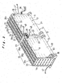
- Fig. 3 shows a battery power source assembly 8 constituted of a left and right pair of battery power source devices 6, 6.
- Each battery power source device 6 is constructed by holding within a holder casing 10 a total of 21 battery modules 9 arranged in parallel in three rows transversely and seven rows vertically, each module being constituted by connecting electrically and mechanically in series a row of six single cells 7.
- series connection is effected between single cells 7 using spot welds S, by means of metal connecting rings 50.
- square nuts 11 provided with seats 11a are connected to single cells 7 at the plus electrode end using spot welding by means of connecting rings 50, at the plus electrode end of battery module 9.
- hexagonal nuts 12 are connected to single cells 7 at the minus electrode end using spot welding by means of connecting rings 50 at the minus electrode end of battery module 9.
- Insulating rings 13a, 13b made of resin are interposed at the connecting parts in order to prevent short circuiting of the plus electrode and minus electrode in the same single cell. These insulating rings 13a, 13b are made of two types of different external diameter; of the total of six insulating rings 13a, 13b, two of these, indicated by 13b, have the larger external diameter.
- a PTC (Positive Temperature Coefficient) sensor 14 is connected to the side circumferential face of each single cell 7.
- This PTC sensor is a temperature sensor in which abnormality is detected by an abrupt increase of electrical resistance which occurs when the temperature of a single cell 7 rises due to some internal abnormality.
- a sensor may be employed whose electrical resistance rises abruptly when a temperature of 80°C is reached.
- a PTC sensor may also be called a "poly sensor”. Sensors other than PTC sensors may of course be used for such temperature sensor 14.
- Six PTC sensors 14 are connected in series by. connecting wire 15, and a terminal element 16 consisting of bendable metal plate is mounted at both ends of these. The two terminal elements 16, 16 are arranged so as to project from both ends of battery module 9.
- outer peripheral surface of battery module 9 is covered by means of an outer tube 17 made of resin such as polyvinyl chloride having electrical insulation and heat shrinkage properties.
- PTC sensor 14 and its connecting wire 15 are protected by single cell 7 and outer tube 17.
- Square nut 11 constituting the plus electrode, hexagonal nut 12 constituting the minus electrode and the two terminal elements 16, 16 are exposed with respect to outer tube 17.
- holder casing 10 is chiefly constituted by main casing body 18, first end plate 19, second end plate 20, three cooling fin plates 21, 21, 21 and two anti-vibration rubber sheets 22, 22.
- Main casing body 18 consists of a unitary resin moulding formed in the shape of a cuboidal box whose upper and lower faces are open.
- the space 26 formed within the two end walls 23, 23 and two side walls 24, 24 constituting four perpendicular walls is practically equally divided into three spaces 26a, 26b, 26c by two partitions 25, 25 parallel to the two end walls 23, 23.
- Cooling fin plates 21 are inserted from above so as to be positioned in the middle respectively of first partitioned space 26a on the side nearest the second end plate 20, second partitioned space 26b in the middle, and third partitioned space 26c on the side nearest first end plate 19, being arranged parallel to the two end walls 23, 23 and fixed to main casing body 18.
- a total of 21 insertion apertures 23a, 25a, 21a in three transverse (horizontal direction) and seven vertical (vertical direction) rows for insertion of battery modules 9 are arranged in the same corresponding positions in end walls 23, 23, partitions 25, 25 and cooling fin plates 21, 21, 21.
- the insertion apertures 23a, 25a, 21a in the three transverse rows and seven vertical rows are arranged with equal pitch in the transverse and vertical directions and are formed so as to have larger diameter than the external diameter of battery modules 9.
- First end plate 19 is screw-fixed to end wall 23 at one end of main casing body 18, by utilising screw holes 70 at its four corners.
- 27 is a frame part formed at the periphery of end wall 23 of main casing body 18 so as to receive first end plate 19 fitting within it.
- Second end plate 20 is releasably held on end wall 23 at the other end of main casing body 18. Specifically, second end plate 20 is held fitted in a movable condition on a frame 27 formed at the other end of main casing body 18.
- first end plate 19 is constituted by a resin plate and has a bus bar 28 embedded and fixed in this resin plate by insertion moulding.
- On the inside face 29 of the resin plate there are provided square-shaped holding recesses 30a for holding, fitted therein, the square nut 11 constituting the plus electrode terminal of a battery module 9 and hexagonal-shaped holding recesses 30b for holding, fitted therein, the hexagonal nut 12 constituting the minus electrode terminal of a battery module 9.
- These holding recesses 30a, 30b are provided in corresponding positions to insertion apertures 23a, 25a, 21a and are provided in a total number of 21 in three transverse rows and seven vertical rows.
- holding recess 30a,30b are arranged alternately in a relationship such that, of adjacent recesses, one of these is a plus-side square-shaped holding recess 30a while the other is a minus-side hexagonal-shaped holding recess 30b.
- Holding recesses 30a, 30b are formed of such shape that nuts 11, 12 of the electrode terminals of battery module 9 fit thereinto, so square nut 11 can only be held in square holding recess 30a and the possibility of its being accidentally held in hexagonal holding recess 30b can be forestalled.
- a total of 21 locking recesses 32a, 32b are formed in the outside face 31 of first end plate 19 in positions corresponding to holding recesses 30a, 30b.
- the shapes of these locking recesses 32a, 32b are of two types, namely, square and hexagonal: square locking recesses 32a are of exactly the same shape as square holding recesses 30a described above and hexagonal locking recesses 32b are of exactly the same shape as hexagonal holding recesses 30b described above.
- a hexagonal locking recess 32b is provided behind square holding recess 30a and a square locking recess 32a is provided behind hexagonal holding recess 30b, respectively.
- first end plate 19 is assembled into main casing body 18 in a condition as described above but, when a right-side battery power source device 6 is employed, first end plate 19 is assembled into main casing body 18 with recesses corresponding to locking recesses 32a, 32b reversed as between the inside and outside faces so that they are employed as holding recesses 30a, 30b.
- Metal bus bars 28 that effect electrical connection between the terminals of battery modules 9 are embedded and fixed by insertion moulding such as to be positioned in the middle in the thickness direction of the resin plate of first end plate 19. Bus bars 28 are exposed to the outside at portions surrounded by holding recesses 30a, 30b and locking recesses 32a, 32b.
- Through-holes 33 are provided in the middle of such exposed portions.
- hexagonal nut 12 constituting the minus electrode of battery module 9 is held fitted in, without any possibility of confusion, in the minus-side hexagonal holding recess 30b, so the minus electrode of battery module. 9 is reliably connected to the minus portion of a bus bar 28.. Also, since nuts 11 and 12 are prevented from rotation by holding recesses 30a, 30b, the locking operation by means of bolt 34 can proceed smoothly.
- second end plate 20 is constituted of a resin plate and a bus bar 28 is embedded and fixed in the resin plate by insertion moulding. Its inside face 29 is provided with holding recesses 30a, 30b while its outside face 31 is provided with locking recesses 32a, 32b.
- nuts 11, 12 at the ends of battery modules 9 are electrically and mechanically locked to bus bar 28 by means of bolts 34.
- Hexagonal holding recesses 30b of second end plate 20 are of course arranged in locations facing square holding recesses 30a of first end plate 19, while square holding recesses 30a of second end plate 20 are arranged in locations facing hexagonal holding recesses 30b of first end plate 19.
- the 21 battery modules 9 which are arranged in parallel in battery power source devices 6 are electrically connected in series by means of bus bars 28 of first end plate 19 and bus bars 28 of second end plate 20.
- the bus bars 28 embedded and fixed in first end plate 19 are eleven in number, and are indicated in Fig. 10 by S1 S3, S5, S7, S9, S1 S13, S15, S17, S19, and S21.
- the bus bars 28 that are embedded in fixed in second end plate 20 are eleven in number are indicated in Fig. 13 by S2, S4, S6, S8, S10, S12, S14, S16, S18, S20, and S22.
- the connection relationship of these with battery modules 9 is shown in Fig. 15.
- bus bars indicated by 31 and S22 should be called a minus terminal bar in the case of the former or a plus terminal bar in the case of the latter, rather than bus bars. Although this is not included in the concept of a bus bar according to the present invention, for convenience in description of this embodiment, they are called bus bars and will be described below.
- the bus bars indicated by S2 ⁇ S21 have a contact with the plus electrode and a contact with the minus electrode of the battery modules 9 that are electrically adjacent in series; thus these adjacent battery modules 9 are electrically connected in series. For example as shown in Fig.
- the bus bar indicated by S2 is provided with a plus electrode contact 2a and a minus electrode contact 2b, while the bus bar indicated by S21 is equipped with a plus electrode contact 21a and minus electrode contact 21b.
- the contact indicated by 1ab in Fig. 15 is the minus terminal for the entire battery power source assembly 8. To this is connected connecting end ring 35a (see Fig. 7) of motive power cable 35 connected to the battery driven motor. Also, the contact indicated by 22ab in Fig. 15 is the plus terminal of one of the battery power source devices 6. To this is connected the connecting end of a connection cable 36 (see Fig. 3) connected to the minus terminal .of the other battery power source device 6. The voltage between the two contacts 1ab and 22ab is about 125 V. Connecting cable 36 has flexibility so that electrical connection between the two battery power source devices 6, 6 can be reliably performed even if there is movement of second end plate 20 due to thermal expansion/contraction of battery modules 9.
- leads 37 for measurement of the voltage between the terminals of the units of the two battery modules 9, 9 are embedded in a resin plate by insertion moulding.
- leads 37 are respectively connected to bus bars 28 indicated by S1, S3, S5, S7, S9, S11, S13, S15, S17, S19, and S21 such that the voltage V 1-3 between bus bars S1 and S3 for example or the voltage V 19-21 between bus bars S19 and S21 can be measured.
- Voltage V 1-3 indicates the voltage between the two battery modules 9, 9 that are electrically connected in series between bus bar S1 and bus bar S3, in other words the voltage across the twelve single cells 7 while the voltages V 3-5 , V 5-7 , ..., V 19-21 shown in Fig. 15 likewise indicate the voltage between the two battery modules 9, 9.
- Leads 37 are arranged as shown in Fig. 10 within the resin plate of first end plate 19 and are collected into a single location on one side of first end plate 19, where they are brought together and extracted to the outside. As shown in Fig. 7, leads 37 are fixed to a resin sheet 38 in the form of a tape and lead to a voltage measurement unit.
- leads 37 is only provided in first end plate 19, while no wiring at all is provided in second end plate 20.
- a holding element 43 for connecting terminal element 16 of connecting wire 15 whereby six of the aforesaid PTC sensors 14 are connected in series is fixed to the resin plate by insertion moulding in first end plate 19.
- Holding element 43 is provided with a screw hole 45 exposed at a through-hole aperture 44 provided in first end plate 19. Then, after inserting terminal element 16 into through-hole aperture 44, it is bent and, next, using a screw 46, as shown in Fig. 12, terminal element 16 is electrically and mechanically connected to holding element 43.
- Holding element 43 is provided at both ends with two screw holes 45, 45 and acts as a bus bar effecting electrical connection of terminal elements 16, 16 of adjacent connecting wires 15.
- a holding element indicated by P in Fig. 10 and Fig. 16 has only a single screw hole 45 and acts solely as the minus terminal.
- a holding element 43 as described above is also fixed in second end plate 20 in the resin plate by insert forming as shown in Fig. 13.
- the holding element 43 of this second end plate 20 is also provided with two screw holes 45, 45 and acts as a bus bar.
- the holding element indicated by Q in Fig. 13 and Fig. 16 has only a single screw hole 45 and serves solely as a plus terminal.
- Fig. 16 shows a condition in which PTC sensors 14 connected to all 126 single cells 7 that are provided in battery power source device 6 are connected electrically in series by means of holding elements 43 of first end plate 19 and second end plate 20. Since this is the same as the case where battery modules 9 shown in Fig. 15 are connected electrically in series using bus bars 28, a detailed description is omitted.
- Respective external lead-out wires 47, 48 are connected (see Fig. 3) to holding element 43 constituting the minus terminal and indicated by P and to holding element 43 constituting the plus terminal and indicated by Q and are connected to a resistance measurement device 49.
- a resistance measurement device 49 As a result of the enormous increase in resistance of PTC sensor 14 connected to a single cell 7 when there is an abnormal rise in temperature in one of the aforementioned 126 single cells 7, this abnormality can be detected by resistance measurement device 49. Consequently, by means of a straightforward construction in which the number of external lead-out wires 47, 48 is a minimum of two, it is possible to detect abnormal rise in temperature of all the single cells 7 of battery power source 6. A like arrangement is provided in the other battery power source device 6 constituting battery power source assembly 8.
- both ends of 21 battery modules 9 are fixed and supported in the first end plate 19 and second end plate 20 in the holder casing 10 of battery power source device 6. Also, battery modules 9 are supported in insertion holes 25a of the partitions 25, 25 by meansof anti-vibration rings 51, 51 at two locations at positions about 1/3 of their lengths respectively from both ends in their longitudinal directions.
- anti-vibration rings 51 are integrally formed on anti-vibration rubber sheet 22 in such a way that they project from its front surface.
- Anti-vibration rubber sheet 22, which is provided with 21 anti-vibration rings 51 is mounted along one face of partition 25 by pressing in all the anti-vibration rings 51 into insertion holes 25a of partition 25.
- holder casing 10 is partitioned into three spaces by means of two partitions 25, 25. Specifically, in order from the second end plate 20 to the first end plate 19, these are first partitioned space 26a, second partitioned space 26b, and third partitioned space 26c. In the middle of each partitioned space 26a, 26b, 26c, a cooling adjustment fin plate 21 is inserted from above and fixed to main casing body 18. Fig. 8 and Fig.
- cooling adjustment fins 52 (including first stage fin 52a, second stage fin 52b, third stage fin 52c, fourth stage fin 52d, fifth stage fin 52e, sixth stage fin 52f, seventh stage fin 52g, and eighth stage fin 52h) that are formed on cooling adjustment fin plate 21 and battery modules 9 that are freely inserted in insertion holes 21a of cooling adjustment fin plate 21.
- means are required in battery power source device 6 for cooling the batteries in order to prevent abnormal rise in temperature produced by evolution of heat by the batteries.
- the lower aperture of holder casing 10 constitutes an air introduction section 53 while its upper aperture constitutes an air extraction section 54. Cooling of the battery modules 9, which are arranged horizontally in seven vertical rows and three transverse rows is performed by means of an air current flowing from the bottom (upstream side) to the top (downstream side).
- cooling adjustment fins 52 project in both directions from the main plate body 21 of cooling adjustment fin plate 21 and extend to a position adjacent partitions 25, 25 so as to adjust the direction of flow and the flow rate of the air current.
- a first stage fin 52a is provided that is arcuate in cross-section about the bottom side of three respective insertion holes 21a I (the seven insertion holes from the first stage to the seventh stage are respectively indicated by I ⁇ VII in Fig. 17) of the lowest stage (also called the first stage), as shown in Fig. 17, so as to severely reduce the ratio of the amount of air directly incident on to first-stage battery module 9.
- a second-stage fin 52b, third stage fin 52c, and fourth stage fin 52d of flat H-shape with an interruption section in cross-section are provided in vertically intermediate positions between corresponding insertion holes in, respectively, first stage three insertion holes I and the second stage three insertion holes II thereabove, second stage three insertion holes II and the third stage threeinsertion holes III thereabove, and third stage three insertion holes III and the fourth stage three insertion holes IV thereabove.
- Second stage fin 52b is formed with interrupting sections t, t on both sides of the portion of H-shaped cross-section; third stage fin 52c is formed with an interrupting portion t 1 in the middle of the portion of H-shaped cross-section; and fourth stage fin 52d is formed with an interrupting portion t 2 of greater width in the middle of the portion of H-shaped cross-section.
- fifth stage fins 52e consisting of four fins arranged next to each other transversely and consisting of two fins of vertically elongate elliptical cross-sectional shape (those shown in Fig. 17 are hollow in cross-section in order to reduce weight, but fins which are not hollow could be employed) and two fins of vertically elongate semi-elliptical cross-section (which could be hollow or not).
- the two fins of vertically elongate elliptical cross-section that are positioned in the middle are arranged at the centre-points of the four insertion holes IV, IV, V, V in the vertical and horizontal directions of their respective peripheries, while the two fins of vertically elongate semi-elliptical cross-section that are positioned at both ends are located on the outside vertically in the middle of corresponding vertical insertion apertures IV and V, so as to make contact with the side edge of main plate and body section 21b.
- stage fins 52f and seven stage fins 52g consisting of four fins in the same relative positions and of practically the same shape as fins 52e of the fifth stage.
- eighth stage fins 52h consisting of four fins in the same positional ' relationship as seventh stage fins 52g, being fins of a shape wherein the upper half of the fins of seventh stage fins 52g is omitted.
- the cross-sectional area of the fins of sixth stage fins 52f is larger than the cross-sectional area of the fins of fifth stage fins 52e and the cross-sectional areas of the fins of seventh stage fins 52g is larger than the cross-sectional area of the fins of sixth stage fins 52f.
- the flow path of the air current formed between battery module 9 and cooling adjustment fins 52 is throttled as one goes further in the upwards direction, so that the flow rate of air flowing through the peripheral region of battery module 9 of the fifth stage is larger than the flow rate of air flowing through the peripheral region of battery module 9 of the fourth stage, the flow rate of air flowing through the peripheral region of sixth stage battery module 9 is increased from the flow.rate of air flowing through the peripheral region of the battery . module 9 of the fifth stage, and the flow rate of air flowing through the peripheral region of the seventh stage battery module is greater than the flow rate of air flowing through the peripheral region of battery module 9 of the sixth stage.
- This utilises the fact that, when the flow rate of an air current increases, its cooling effect increases in proportion to the square root.
- the air cooling structure of battery modules 9 was described above taking as example the case of second partitioned space 26b; however, the air cooling structure in the other, namely, the first partitioned space 26a and third partitioned space 26c is constructed in the same way.
- the air cooling structure in the other namely, the first partitioned space 26a and third partitioned space 26c is constructed in the same way.
- the battery modules 9 belonging to the lower-stage side groups in the case shown in Fig.
- the air current is throttled, so as to raise the flow speed of the air current around battery modules 9.
- these gaps are made progressively narrower going towards the upper stages (fifth stage, sixth stage and seventh stage) to raise the flow rate of the air current around battery modules 9 so as to compensate for the loss of cooling effect of the air as it is gradually heated up as it rises: thus practically uniform cooling of the battery modules 9 in each stage (fifth stage ⁇ seventh stage) can be achieved.
- the batteries used in this embodiment are nickel-hydrogen secondary cells, it is necessary to devise safety measures in respect of hydrogen leakage in the event of abnormality from the battery cans.
- the air is fed into battery power source device 6 by pressure feed by a fan 5 equipped with a sirocco fan.
- a fan 5 equipped with a sirocco fan.
- it is in particular vital to give consideration to ensuring that hydrogen cannot be fed into the vicinity of fan 5 and the interior of motor 57 that drives this and/or their vicinity. Accordingly, in this embodiment, as shown in Fig. 8, Fig. 17 and Fig.
- fan 5 and motor 57 are arranged to the side and underneath holder casing 10 and fan aperture 58 is arranged below holder casing 10, so that air.that is pressure-fed from fan 5 passes through air supply chamber 59 formed below outer casing 4, and reaches air introduction section 53 at the bottom end of holder casing 10, and then cools battery modules 9 by flowing through holder casing 10 from the bottom to the top, then issues from air extraction section 54 of holder casing 10, after which it passes through air discharge chamber 60 formed above outer casing 4 and is discharged to the outside of outer casing 4 from a discharge port 61 formed in the upper side end of outer casing 4.
- Fig. 18 shows a construction in which cooling air is pressure-fed to left and right battery power source devices 6, 6 by a single fan 5.
- Fan 5 is equipped with a pair of left and right sirocco fans and fan apertures 58, 58; it extracts air within the vehicle from air extraction port 62 and feeds air uniformly from the pair of fan apertures 58, 58 into left and right air supply chambers 59, 59.
- Air supply chambers 59 are constituted by a space enclosed by a bottom sheet part 4a of outer casing 4, the front wall 4b that stands erect in a front position in Fig. 18 of bottom sheet 4a, and the bottom face of holder casing 10.
- At an inlet 63 facing fan aperture 58 there are provided a plurality of curved flow alignment guides 64a, 64b, 64c erected on bottom sheet 4a for guiding air. from fan aperture 58 inwards and sideways.
- Inlet 63 is arranged in the middle in the width direction of outer casing 4, being arranged so as to be positioned below first partitioned space 26a of holder casing 10.
- Bottom sheet 4a is formed so that, within air supply chamber 59, it has a slope 65 going gradually upwards towards the outside i.e. towards second partitioned space 26b and third partitioned space 26c, and has a slope 66 going gradually upwards towards the inside..
- An air current direction guide 67 of small height that leads the air upwards is provided at a position on slope 65 below the boundary of second partitioned space 26b and third partitioned space 26c (see Fig. 8).
- the air that is extracted from inlet 63 is fed through two air passages formed in each space between the three flow alignment guides 64a, 64b and 64c into the inside and into second and third partitioned spaces 26b, 26c, while part of it is fed into first partitioned space 26a.
- an air current direction guide 68 that directs the air upwards in the vicinity of the inlet to the air passage nearest second end plate 20.
- Air current direction guide 67 is provided in order to ensure that there is no insufficiency in the amount of air that.is fed into second partitioned space 26b at this point. The air that is led to below third partitioned Space 26c is then led into third partitioned space 26c.
- air current direction guide 67 such as to make the amount of air that is directed into second partitioned space 26b rather larger than the amount of air that is directed into the other partitioned spaces 26a, 26c.
- outer casing 4 is provided with a holder casing mounting seat 71 on its bottom sheet 4a and the left and right holder casings 10, 10 are mounted and fixed in a foot portion 72 thereof by means of bolts and nuts 73. Also, a flange 74 is provided mounted on the main automobile body at the periphery of outer casing 4.
- a safety plug 75 in order to cut off temporarily this series connection.
- a bypass may be provided whereby the locations indicated by 17a and 17b and an openable safety plug 75 are connected by leads 76, 77 by for example severing S17 bus bars 28 at a location indicted by N in subsequent processing, after exposing these at an aperture provided in first end plate 19.
- uniform cooling can be performed of the battery modules which are arranged parallel to each other in large numbers in the holder casing, and cooling that is uniform as between the single cells constituting the battery modules can also be achieved.
- the problem that the cooling effect of the cooling air is lowered because of its increased temperature on the downstream side compared with the upstream side is solved, thereby making it possible to effect uniform cooling of the battery modules whether they are on the upstream side or downstream side.
- efficient utilisation of the air current can be achieved by preventing over-cooling of the battery modules on the upstream side.
- cooling of a battery power source employing nickel-hydrogen secondary cells can be performed whilst maintaining safety in regard to hydrogen.
- cooling of a battery power source assembly comprising a pair of battery power source devices can be performed in a uniform manner for all the battery modules by using only a single pressure-feed fan.
Abstract
Description
- The present invention relates to a cooling device that cools a battery power source device, used as a motor drive source or the like for an electrically powered automobile, comprising by air cooling.
- In a known type of battery power source of this kind, a large number of battery modules constituted by connecting electrically and mechanically in series a row consisting of a plurality of single cells are arranged in parallel and held in a holder casing. High voltage power is extracted by connecting these battery modules electrically in series.
- The present inventors developed a battery power source device wherein a large number of battery modules are arranged in parallel in a holder casing comprising a main casing body and two end plates, series electrical connection between the battery modules being achieved by holding ends of the battery modules in holding apertures provided in the end plates and locking the ends of the battery modules to a metal bus bar arranged on the outside face of the end plates.
- However, with this prior example, there was the serious problem of how to restrain the rise in temperature produced by evolution of heat from the battery modules tightly packed in the holder casing.
- Furthermore, since nickel-hydrogen secondary cells were employed as the cells of a battery power source device of this type, and, under abnormal conditions, leakage of hydrogen from the cell cans may occur, safe measures for dealing with such hydrogen leakage posed a serious challenge.
- Also, an arrangement is known in which high voltage power is supplied in an electrically powered automobile by mounting therein battery power source assemblies comprising a pair of battery power source devices electrically connected in series. However, in this case, efficient cooling of the battery power source devices presented a serious problem.
- In order to suppress rising temperature brought about by evolution of heat from the batteries in the above battery power source device, the inventors modified the design of the holder casing and developed a cooling device having an air flow guide such as to make a suitable amount of cooling air flow along the battery modules.
- However, with this prior example, not only was it difficult to suitably distribute the flow of air in regard to the battery modules but also it was difficult to effect uniform cooling between the single cells connected in series to constitute the individual battery modules. Specifically, the air flowing along the battery modules rises in temperature due to the heat received from the single cells whilst it is flowing from the upstream side to the downstream side, causing its cooling effect to gradually diminish. Thus it was extremely difficult to compensate for this by individually controlling the air flow rate and air flow speed for each individual battery module in order to achieve uniform cooling of the individual unit cells from the upstream side to the downstream side.
- A main object of the present invention is therefore to provide a battery power source device whereby the above problems of the prior examples are eliminated and voltage detection of the battery modules and/or detection of abnormal temperature rise of the single cells can be performed in a convenient manner with a simple construction.
- Further, an object of the present invention is to solve the problems of the prior examples and to provide safety measures in respect of hydrogen leakage and a cooling device of a comparatively simple structure whereby cooling of a battery power source assembly comprising a pair of battery power source devices can be achieved in an efficient manner.
- In order to solve the above problem, the present invention exists as battery power source comprising a cooling device and a large number of battery modules constituted by connecting a plurality of single cells in a row electrically and mechanically in series are arranged parallel to each other and held in a holder casing and air is forcibly made to flow in one direction within this holder casing thereby cooling the large number of battery modules in the holder casing wherein the direction of flow of the air is a direction at right angles to the longitudinal direction of the battery modules, and further wherein said angle cells (7) are nickel hydrogen secondary cells.
- With a battery power source according to the present invention, since the direction of flow of the cooling air is a direction at right angles to the longitudinal direction of the battery modules, mutual cooling of the single cells that constitute the battery modules can easily.be performed in a uniform manner without adopting special expedients and countermeasures in respect of the lowering of cooling effect produced by rise in temperature of the air occurring whilst it flows from the upstream to the downstream side can be carried out comparatively easily for the battery power source device as a whole rather than needing to be carried out at the level of individual battery modules, as in the prior art. According to the invention a construction may suitably be adopted wherein the single cells are nickel-hydrogen secondary cells; the battery modules are arranged horizontally and air is made to flow from bottom to top; the battery modules are held in the holder casing arranged horizontally in matrix fashion on respective vertical and transverse straight lines; and furthermore means for forcibly making air flow in one direction is a pressure-feed type fan arranged on the upstream side of the holder casing.
- In particular in a battery power source device in which nickel-hydrogen secondary cells are employed, if a pressure-feed type fan is arranged on the upstream side and cooling of the battery modules is effected by causing air to flow forcibly from bottom to top in the holder casing, even if there should happen to be any leakage of hydrogen from the battery modules, delivery of hydrogen to the side of the pressure-feed fan can be reliably prevented and as a result safety in regard to hydrogen leakage can be ensured.
- According to the invention a construction may be adopted wherein, in a battery power source, the two ends of battery modules are supported in the two end plates of the holder casing, a cooling adjustment fin plate provided with insertion holes in which the battery modules are freely inserted is assembled with the holder casing demountably and parallel with these at an intermediate location between the two end plates, and fins for the means for flow alignment and/or fins for the means for screening are integrally provided on the cooling adjustment fin plate.
- By adopting this construction, uniform cooling of the battery modules can be achieved and a cooling device can be provided wherein assembly of a cooling adjustment fin plate on the holder casing can be achieved easily with a straightforward construction.
- In order to solve the above problems the present invention provides a battery power source comprising a cooling device and a pair of left and right battery power source devices constituted by holding a large number of battery modules consisting of a plurality of single cells connected in a row electrically and mechanically in series arranged horizontally and parallel to each other in a holder casing, respective air supply chambers being formed below these holder casings and wherein air is fed to a lower aperture of the holder casing of the respective battery power source devices through left and right air supply chambers from a pressure-feed fan so that the battery module is cooled by the air current that is discharged from an upper aperture after rising through the holder casings wherein the pressure-feed fan has two blowing ports that supply air in the direction parallel to the end plates into the respective battery power source devices, these blowing ports opening in positions close to a respective one end plate of the battery power source devices, the bottom faces of the air supply chambers being formed with a slope whereby the cross-sectional area of the flow path gradually diminishes from the one end plate side towards the other end plate side.
- With the above invention, delivery of air into the left and right battery power source device can be achieved with a single pressure-feed type fan and, due to the provision of the slope, variation of the amount of air that is taken into the holder casing from the air supply chamber depending on the position in the direction from one end plate towards the other end plate in each battery power source device can be prevented.
- According to the invention a construction may be adopted wherein, in the vicinity of the inlet of an air supply chamber, there is provided a flow alignment guide that alters the direction of flow of the incoming air delivered from the blowing port that opens in a position close to one end plate towards the other end plate; and in which, in the vicinity of the inlet of an air supply chamber, there is provided a flow alignment guide that guides the direction of flow of the incoming air delivered from the blowing port upwards; and furthermore in which an air current direction guide is provided that directs upwardly the direction of flow of air at the slope of the bottom face of the airsupply chamber and constructed so as to ensure the amount of air flow that is delivered to a location positioned intermediate the two end plates of the holder casing.
- By means of this construction, air flowing in from the inlet of an air supply chamber in a position close to one end plate can be guided smoothly to the other end plate by the flow alignment guide and, by the air current direction guide that is provided in the vicinity of the inlet of the air supply chamber, air is prevented from passing straight through and the amount of air that is delivered into the holder casing from a location in the vicinity of the inlet can be guaranteed. Furthermore, since the amount of air that is delivered to a location positioned intermediate the two end plates of the holder casing can be guaranteed by the air current direction guide that is provided on the slope, supply of cooling air within the holder casing can be performed in a uniform manner over the entire region without any possibility of being concentrated at a specific location. As a result, air cooling of the large number of battery modules within the two battery power source devices can be performed uniformly and effectively.
- These and other objects, features and advantages of the present invention will be apparent from the following description of the preferred embodiments of the invention in conjunction with the accompanying drawings, in which:
- Fig. 1 is a diagrammatic side view showing the relationship between an automobile and a battery pack unit;
- Fig. 2 is a perspective view showing an outline of a battery pack unit;
- Fig. 3 is a perspective view showing a battery power source assembly;
- Fig. 4A is a front view showing a battery module, Fig. 4B is a left side view thereof, and Fig. 4C is a right side view thereof;
- Fig. 5.is a perspective view of a battery module in which an outer tube is shown by an imaginary line;
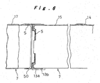
- Fig. 6 is a cross-sectional view with part broken away showing major parts of a battery module;
- Fig. 7 is an exploded perspective view of a battery power source device;
- Fig. 8 is a cross-sectional view showing a battery power source device;
- Fig. 9 is a cross-sectional view to a larger scale showing major parts of a battery power source device;
- Fig. 10 is a front view of a first end plate seen from the side of the inner surface;
- Fig. 11A is a cross-sectional view to a larger scale along the line A-A of Fig. 10 and Fig. 11B is a front view thereof;
- Fig. 12 is a cross-sectional view to a larger scale along the line B-B of Fig. 10;
- Fig. 13 is a front view of a second end plate seen from the side of the outer surface;
- Fig. 14 is a cross-sectional view to a larger scale along the line C-C of Fig. 13;
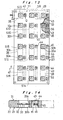
- Fig. 15 is a diagram showing how a battery module is connected;
- Fig. 16 is a diagram showing how a PTC sensor is connected;
- Fig. 17 is a cross-sectional view of a battery pack unit; and
- Fig. 18 is an exploded perspective view of a battery pack unit.
-
- Fig. 1 shows a hybrid type automobile whose locomotive drive source is constituted by combining an internal combustion engine and a battery driven motor. In this hybrid type automobile, the internal combustion engine is operated under optimum conditions and when output is insufficient for the running conditions, this output deficiency is made up by the output of the battery driven motor; and by performing regenerative power absorption during deceleration the distance of travel per unit of fuel is enormously increased in comparison with an automobile in which an ordinary internal combustion engine is used on its own.
- As the electric power source of the battery driven motor, nickel-hydrogen secondary cells are employed, these being accommodated in a
battery pack unit 1 shown in Fig. 1 and Fig. 2. Thisbattery pack unit 1 is arranged in the space between the rear seat 2 and the boot 3 behind it. -
Battery pack unit 1 comprises anoutside casing 4 consisting of a resin moulding, afan 5 arranged therein, and a pair of left and right batterypower source devices outer casing 4. In each batterypower source device 6, there are provided 126 electrically . series-connected single cells (also called battery cells) constituted by nickel-hydrogen secondary cell units; this enables power supply of voltage about 125 V. Left and right batterypower source devices - Fig. 3 shows a battery power source assembly 8 constituted of a left and right pair of battery
power source devices - Each battery
power source device 6 is constructed by holding within aholder casing 10 a total of 21battery modules 9 arranged in parallel in three rows transversely and seven rows vertically, each module being constituted by connecting electrically and mechanically in series a row of sixsingle cells 7. - As shown in Fig. 4, Fig. 5 and Fig. 6, in a
battery module 9, series connection is effected betweensingle cells 7 using spot welds S, by means ofmetal connecting rings 50. Also,square nuts 11 provided withseats 11a are connected tosingle cells 7 at the plus electrode end using spot welding by means of connectingrings 50, at the plus electrode end ofbattery module 9. Furthermore,hexagonal nuts 12 are connected tosingle cells 7 at the minus electrode end using spot welding by means of connectingrings 50 at the minus electrode end ofbattery module 9. The dimension between the opposite sides ofsquare nut 11 and the dimension between the opposite sides ofhexagonal nut 12 are made the same so that there is no possibility of thesenuts square holding recess 30a or ahexagonal holding recess 30b, to be described. Insulatingrings rings insulating rings - A PTC (Positive Temperature Coefficient)
sensor 14 is connected to the side circumferential face of eachsingle cell 7. This PTC sensor is a temperature sensor in which abnormality is detected by an abrupt increase of electrical resistance which occurs when the temperature of asingle cell 7 rises due to some internal abnormality. For example a sensor may be employed whose electrical resistance rises abruptly when a temperature of 80°C is reached. A PTC sensor may also be called a "poly sensor". Sensors other than PTC sensors may of course be used forsuch temperature sensor 14. SixPTC sensors 14 are connected in series by. connectingwire 15, and aterminal element 16 consisting of bendable metal plate is mounted at both ends of these. The twoterminal elements battery module 9. - The outer peripheral surface of
battery module 9 is covered by means of anouter tube 17 made of resin such as polyvinyl chloride having electrical insulation and heat shrinkage properties.PTC sensor 14 and its connectingwire 15 are protected bysingle cell 7 andouter tube 17.Square nut 11 constituting the plus electrode,hexagonal nut 12 constituting the minus electrode and the twoterminal elements outer tube 17. - As shown in Fig. 3, Fig. 7 and Fig. 8,
holder casing 10 is chiefly constituted bymain casing body 18,first end plate 19,second end plate 20, three coolingfin plates anti-vibration rubber sheets -
Main casing body 18 consists of a unitary resin moulding formed in the shape of a cuboidal box whose upper and lower faces are open. Thespace 26 formed within the twoend walls side walls spaces partitions end walls fin plates 21 are inserted from above so as to be positioned in the middle respectively of firstpartitioned space 26a on the side nearest thesecond end plate 20, secondpartitioned space 26b in the middle, and thirdpartitioned space 26c on the side nearestfirst end plate 19, being arranged parallel to the twoend walls main casing body 18. - A total of 21
insertion apertures battery modules 9 are arranged in the same corresponding positions inend walls partitions cooling fin plates insertion apertures battery modules 9. -
First end plate 19 is screw-fixed to endwall 23 at one end ofmain casing body 18, by utilising screw holes 70 at its four corners. 27 is a frame part formed at the periphery ofend wall 23 ofmain casing body 18 so as to receivefirst end plate 19 fitting within it.Second end plate 20 is releasably held onend wall 23 at the other end ofmain casing body 18. Specifically,second end plate 20 is held fitted in a movable condition on aframe 27 formed at the other end ofmain casing body 18. - As shown in Fig. 7 ∼ Fig. 12,
first end plate 19 is constituted by a resin plate and has abus bar 28 embedded and fixed in this resin plate by insertion moulding. On theinside face 29 of the resin plate there are provided square-shaped holding recesses 30a for holding, fitted therein, thesquare nut 11 constituting the plus electrode terminal of abattery module 9 and hexagonal-shaped holding recesses 30b for holding, fitted therein, thehexagonal nut 12 constituting the minus electrode terminal of abattery module 9. These holdingrecesses insertion apertures recess holding recess 30a while the other is a minus-side hexagonal-shapedholding recess 30b. Holdingrecesses nuts battery module 9 fit thereinto, sosquare nut 11 can only be held insquare holding recess 30a and the possibility of its being accidentally held inhexagonal holding recess 30b can be forestalled. - A total of 21
locking recesses outside face 31 offirst end plate 19 in positions corresponding to holdingrecesses recesses recesses 32a are of exactly the same shape as square holdingrecesses 30a described above and hexagonal locking recesses 32b are of exactly the same shape as hexagonal holding recesses 30b described above. As shown in Fig. 10, ahexagonal locking recess 32b is provided behind square holdingrecess 30a and asquare locking recess 32a is provided behindhexagonal holding recess 30b, respectively. The purpose of this construction is to make it possible to use in common respective identicalfirst end plates power source devices power source device 6 is employed,first end plate 19 is assembled intomain casing body 18 in a condition as described above but, when a right-side batterypower source device 6 is employed,first end plate 19 is assembled intomain casing body 18 with recesses corresponding to lockingrecesses recesses - Metal bus bars 28 that effect electrical connection between the terminals of
battery modules 9 are embedded and fixed by insertion moulding such as to be positioned in the middle in the thickness direction of the resin plate offirst end plate 19. Bus bars 28 are exposed to the outside at portions surrounded by holdingrecesses recesses - Through-
holes 33 are provided in the middle of such exposed portions. -
Nuts battery module 9, in a condition in which they are held fitted into holdingrecesses bolt 34 that is inserted through through-hole 33. from the side of lockingrecesses bolts 34,nuts bus bar 28. Sincesquare nut 11 that constitutes the plus electrode ofbattery module 9 is held fitted into the plus-side square holdingrecess 30a without any possibility of confusion, the plus electrode ofbattery module 9 is reliably connected to the plus portion ofbus bar 28. Likewise,hexagonal nut 12 constituting the minus electrode ofbattery module 9 is held fitted in, without any possibility of confusion, in the minus-sidehexagonal holding recess 30b, so the minus electrode of battery module. 9 is reliably connected to the minus portion of abus bar 28.. Also, sincenuts recesses bolt 34 can proceed smoothly. - As shown in Fig. 8, Fig. 13 and Fig. 14, like
first end plate 19,second end plate 20 is constituted of a resin plate and abus bar 28 is embedded and fixed in the resin plate by insertion moulding. Itsinside face 29 is provided with holdingrecesses outside face 31 is provided with lockingrecesses first end plate 19,nuts battery modules 9 are electrically and mechanically locked tobus bar 28 by means ofbolts 34. Hexagonal holding recesses 30b ofsecond end plate 20 are of course arranged in locations facing square holding recesses 30a offirst end plate 19, while square holding recesses 30a ofsecond end plate 20 are arranged in locations facing hexagonal holding recesses 30b offirst end plate 19. - The 21
battery modules 9 which are arranged in parallel in batterypower source devices 6 are electrically connected in series by means ofbus bars 28 offirst end plate 19 andbus bars 28 ofsecond end plate 20. The bus bars 28 embedded and fixed infirst end plate 19 are eleven in number, and are indicated in Fig. 10 by S1 S3, S5, S7, S9, S1 S13, S15, S17, S19, and S21. The bus bars 28 that are embedded in fixed insecond end plate 20 are eleven in number are indicated in Fig. 13 by S2, S4, S6, S8, S10, S12, S14, S16, S18, S20, and S22. The connection relationship of these withbattery modules 9 is shown in Fig. 15. - Strictly speaking, the bus bars indicated by 31 and S22 should be called a minus terminal bar in the case of the former or a plus terminal bar in the case of the latter, rather than bus bars. Although this is not included in the concept of a bus bar according to the present invention, for convenience in description of this embodiment, they are called bus bars and will be described below. The bus bars indicated by S2 ∼ S21 have a contact with the plus electrode and a contact with the minus electrode of the
battery modules 9 that are electrically adjacent in series; thus theseadjacent battery modules 9 are electrically connected in series. For example as shown in Fig. 15, the bus bar indicated by S2 is provided with aplus electrode contact 2a and a minus electrode contact 2b, while the bus bar indicated by S21 is equipped with aplus electrode contact 21a andminus electrode contact 21b. The contact indicated by 1ab in Fig. 15 is the minus terminal for the entire battery power source assembly 8. To this is connected connectingend ring 35a (see Fig. 7) ofmotive power cable 35 connected to the battery driven motor. Also, the contact indicated by 22ab in Fig. 15 is the plus terminal of one of the batterypower source devices 6. To this is connected the connecting end of a connection cable 36 (see Fig. 3) connected to the minus terminal .of the other batterypower source device 6. The voltage between the two contacts 1ab and 22ab is about 125V. Connecting cable 36 has flexibility so that electrical connection between the two batterypower source devices second end plate 20 due to thermal expansion/contraction ofbattery modules 9. - As shown in Fig. 7, Fig. 10, Fig. 12 and Fig. 15, in
first end plate 19, leads 37 for measurement of the voltage between the terminals of the units of the twobattery modules bus bars 28 indicated by S1, S3, S5, S7, S9, S11, S13, S15, S17, S19, and S21 such that the voltage V1-3 between bus bars S1 and S3 for example or the voltage V19-21 between bus bars S19 and S21 can be measured. Voltage V1-3 indicates the voltage between the twobattery modules single cells 7 while the voltages V3-5, V5-7, ..., V19-21 shown in Fig. 15 likewise indicate the voltage between the twobattery modules single cells 7 belonging to the corresponding twobattery modules - Leads 37 are arranged as shown in Fig. 10 within the resin plate of
first end plate 19 and are collected into a single location on one side offirst end plate 19, where they are brought together and extracted to the outside. As shown in Fig. 7, leads 37 are fixed to aresin sheet 38 in the form of a tape and lead to a voltage measurement unit. - As shown in Fig. 10 and Fig. 11, excess current in leads 37 is prevented by mounting
fuses 39 at the junction ofleads 37 and bus bars 28. These fuses 39 are mounted by after-fixing to extensions (fuse mounting elements) 40 for lead connection provided unitarily with bus bars 28. A construction is adopted whereby the front and rear faces of the middle ofextension 40 are exposed to the outside byapertures extension 40 in after-processing,fuse 39 is mounted so as to electrically connect both sides of the disconnected portion (the disconnected portion is shown by an imaginary line in Fig. 11B).Resin moulding 39a is then applied toapertures - The wiring of
leads 37 is only provided infirst end plate 19, while no wiring at all is provided insecond end plate 20. - As shown in Fig. 7, Fig. 10 and Fig. 12, a holding
element 43 for connectingterminal element 16 of connectingwire 15 whereby six of theaforesaid PTC sensors 14 are connected in series is fixed to the resin plate by insertion moulding infirst end plate 19. - Holding
element 43 is provided with ascrew hole 45 exposed at a through-hole aperture 44 provided infirst end plate 19. Then, after insertingterminal element 16 into through-hole aperture 44, it is bent and, next, using ascrew 46, as shown in Fig. 12,terminal element 16 is electrically and mechanically connected to holdingelement 43. - Holding
element 43 is provided at both ends with twoscrew holes terminal elements wires 15. However, a holding element indicated by P in Fig. 10 and Fig. 16 has only asingle screw hole 45 and acts solely as the minus terminal. - A holding
element 43 as described above is also fixed insecond end plate 20 in the resin plate by insert forming as shown in Fig. 13. The holdingelement 43 of thissecond end plate 20 is also provided with twoscrew holes single screw hole 45 and serves solely as a plus terminal. - Fig. 16 shows a condition in which
PTC sensors 14 connected to all 126single cells 7 that are provided in batterypower source device 6 are connected electrically in series by means of holdingelements 43 offirst end plate 19 andsecond end plate 20. Since this is the same as the case wherebattery modules 9 shown in Fig. 15 are connected electrically in series usingbus bars 28, a detailed description is omitted. - Respective external lead-out
wires element 43 constituting the minus terminal and indicated by P and to holdingelement 43 constituting the plus terminal and indicated by Q and are connected to aresistance measurement device 49. As a result of the enormous increase in resistance ofPTC sensor 14 connected to asingle cell 7 when there is an abnormal rise in temperature in one of the aforementioned 126single cells 7, this abnormality can be detected byresistance measurement device 49. Consequently, by means of a straightforward construction in which the number of external lead-outwires single cells 7 ofbattery power source 6. A like arrangement is provided in the other batterypower source device 6 constituting battery power source assembly 8. - As shown in Fig. 3, Fig. 7, Fig. 8 and Fig. 9, both ends of 21
battery modules 9 are fixed and supported in thefirst end plate 19 andsecond end plate 20 in theholder casing 10 of batterypower source device 6. Also,battery modules 9 are supported ininsertion holes 25a of thepartitions anti-vibration rubber sheet 22 in such a way that they project from its front surface.Anti-vibration rubber sheet 22, which is provided with 21 anti-vibration rings 51 is mounted along one face ofpartition 25 by pressing in all the anti-vibration rings 51 intoinsertion holes 25a ofpartition 25. - As already described,
holder casing 10 is partitioned into three spaces by means of twopartitions second end plate 20 to thefirst end plate 19, these are firstpartitioned space 26a, secondpartitioned space 26b, and thirdpartitioned space 26c. In the middle of each partitionedspace adjustment fin plate 21 is inserted from above and fixed tomain casing body 18. Fig. 8 and Fig. 17 show the relationship of cooling adjustment fins 52 (includingfirst stage fin 52a,second stage fin 52b,third stage fin 52c,fourth stage fin 52d,fifth stage fin 52e,sixth stage fin 52f,seventh stage fin 52g, andeighth stage fin 52h) that are formed on coolingadjustment fin plate 21 andbattery modules 9 that are freely inserted ininsertion holes 21a of coolingadjustment fin plate 21. As is well known, means are required in batterypower source device 6 for cooling the batteries in order to prevent abnormal rise in temperature produced by evolution of heat by the batteries. In this embodiment, the lower aperture ofholder casing 10 constitutes anair introduction section 53 while its upper aperture constitutes anair extraction section 54. Cooling of thebattery modules 9, which are arranged horizontally in seven vertical rows and three transverse rows is performed by means of an air current flowing from the bottom (upstream side) to the top (downstream side). - The cooling structure of
battery modules 9 will be described taking as an example second partitionedspace 26b which is located in the middle. As shown in Fig. 7 and Fig. 8, coolingadjustment fins 52 project in both directions from themain plate body 21 of coolingadjustment fin plate 21 and extend to a positionadjacent partitions first stage fin 52a is provided that is arcuate in cross-section about the bottom side of threerespective insertion holes 21a I (the seven insertion holes from the first stage to the seventh stage are respectively indicated by I ∼ VII in Fig. 17) of the lowest stage (also called the first stage), as shown in Fig. 17, so as to severely reduce the ratio of the amount of air directly incident on to first-stage battery module 9. - A second-
stage fin 52b,third stage fin 52c, andfourth stage fin 52d of flat H-shape with an interruption section in cross-section are provided in vertically intermediate positions between corresponding insertion holes in, respectively, first stage three insertion holes I and the second stage three insertion holes II thereabove, second stage three insertion holes II and the third stage threeinsertion holes III thereabove, and third stage three insertion holes III and the fourth stage three insertion holes IV thereabove.Second stage fin 52b is formed with interrupting sections t, t on both sides of the portion of H-shaped cross-section;third stage fin 52c is formed with an interrupting portion t1 in the middle of the portion of H-shaped cross-section; andfourth stage fin 52d is formed with an interrupting portion t2 of greater width in the middle of the portion of H-shaped cross-section. In this way, the ratio of air directly striking secondstage battery module 9 is increased from that in the case of firststage battery module 9; the ratio of air directly striking thirdstage battery module 9 is increased from that of secondstage battery module 9; and the ratio of air directly strikingfourth battery module 9 is increased from that of thirdstage battery module 9. - Between the three insertion holes IV of the fourth stage and the three insertion holes V of the fifth stage on top of these, there are provided
fifth stage fins 52e consisting of four fins arranged next to each other transversely and consisting of two fins of vertically elongate elliptical cross-sectional shape (those shown in Fig. 17 are hollow in cross-section in order to reduce weight, but fins which are not hollow could be employed) and two fins of vertically elongate semi-elliptical cross-section (which could be hollow or not). The two fins of vertically elongate elliptical cross-section that are positioned in the middle are arranged at the centre-points of the four insertion holes IV, IV, V, V in the vertical and horizontal directions of their respective peripheries, while the two fins of vertically elongate semi-elliptical cross-section that are positioned at both ends are located on the outside vertically in the middle of corresponding vertical insertion apertures IV and V, so as to make contact with the side edge of main plate andbody section 21b. Between the three insertion holes V of the fifth stage and the three insertion holes VI of the sixth stage on top of these and between the three insertion holes VI of the sixth stage and the three insertion holes VII of the seventh stage on top of these, there are provided sixstage fins 52f and sevenstage fins 52g consisting of four fins in the same relative positions and of practically the same shape asfins 52e of the fifth stage. Further, in positions above the three insertion holes VII of the uppermost stage (which may also be called the seventh stage), there are providedeighth stage fins 52h consisting of four fins in the same positional ' relationship asseventh stage fins 52g, being fins of a shape wherein the upper half of the fins ofseventh stage fins 52g is omitted. The cross-sectional area of the fins ofsixth stage fins 52f is larger than the cross-sectional area of the fins offifth stage fins 52e and the cross-sectional areas of the fins ofseventh stage fins 52g is larger than the cross-sectional area of the fins ofsixth stage fins 52f. By thus making the cross-sectional areas of coolingadjustment fins battery module 9 andcooling adjustment fins 52 is throttled as one goes further in the upwards direction, so that the flow rate of air flowing through the peripheral region ofbattery module 9 of the fifth stage is larger than the flow rate of air flowing through the peripheral region ofbattery module 9 of the fourth stage, the flow rate of air flowing through the peripheral region of sixthstage battery module 9 is increased from the flow.rate of air flowing through the peripheral region of the battery .module 9 of the fifth stage, and the flow rate of air flowing through the peripheral region of the seventh stage battery module is greater than the flow rate of air flowing through the peripheral region ofbattery module 9 of the sixth stage. This utilises the fact that, when the flow rate of an air current increases, its cooling effect increases in proportion to the square root. - The air cooling structure of
battery modules 9 was described above taking as example the case of secondpartitioned space 26b; however, the air cooling structure in the other, namely, the firstpartitioned space 26a and thirdpartitioned space 26c is constructed in the same way. In each case, of the large number ofbattery modules 9 arranged in multiple stages in parallel in a direction at right angles to the air current flowing upwards from below, regarding thebattery modules 9 belonging to the lower-stage side groups (in the case shown in Fig. 17, those arranged instages 1 to 4) the bottom sides ofbattery modules 9 are covered by screeningfins 52a ∼ 52d that adjust the quantity of air that is directly incident onbattery modules 9 and the quantity of air strikingbattery modules 9 is arranged to progressively increase as one goes from the lowest stage (stage 1) to the upper stages (second stage, third stage, fourth stage). In this way, over-cooling ofbattery modules 9 in the lowest stage is prevented and the amount of air strikingbattery modules 9 is increased going towards the upper stages so as to compensate for the lowering in cooling effect of the air produced by the gradual rise in temperature due to the heat evolved by the batteries. Cooling ofbattery modules 9 of each stage (stage 1 ∼ stage 4) can be thus arranged to be performed practically evenly. - As shown in Fig. 17, most of the air that cools the
battery modules 9 belonging to the lower group rises throughpassages right battery modules 9 and thepassages battery modules 9 andside wall 24. Some of it is extracted tobattery modules 9 and is then again merged withpassages stage battery modules 9. Next, the air current is employed to coolbattery modules 9 belonging to the upper-stage group (in the case shown in Fig. 17, those modules which are arranged in the fifth to seventh stages); however, since it has already cooled thebattery modules 9 of the four stages belonging to the lower group, the air temperature is fairly high, so the cooling effect is lowered. In order to compensate for this, for cooling of thebattery modules 9 belonging to the upper-stage group, the air current is throttled, so as to raise the flow speed of the air current aroundbattery modules 9. Abovepassages type fins 52e ∼ 52h in order to raise the flow speed of the air current by narrowing the gaps betweenbattery modules 9, being arranged diagonally belowbattery modules 9 of the fifth, sixth and seventh stages and diagonally abovebattery modules 9 of the seventh stage. Also, these gaps are made progressively narrower going towards the upper stages (fifth stage, sixth stage and seventh stage) to raise the flow rate of the air current aroundbattery modules 9 so as to compensate for the loss of cooling effect of the air as it is gradually heated up as it rises: thus practically uniform cooling of thebattery modules 9 in each stage (fifth stage ∼seventh stage) can be achieved. - In this way, a construction is obtained in which all the
battery modules 9 are cooled practically uniformly from the lowest stage to the highest stage. It should be noted that although, in this embodiment, a construction was adopted in which practically uniform cooling of all thebattery modules 9 was achieved by usingscreening fins 52a ∼ 52d for the lower fourstage battery modules 9 and flow-path throttling fins 52e ∼ 52h for the upper threestage battery modules 9, adjustment of the air flow etc. would of course be possible by for example using screening fins for the lower threestage battery modules 9, providing no fins corresponding to thebattery modules 9 in the fourth, intermediate stage, and employing flow path throttling fins forbattery modules 9 in the upper three stages. - Since the batteries used in this embodiment are nickel-hydrogen secondary cells, it is necessary to devise safety measures in respect of hydrogen leakage in the event of abnormality from the battery cans. The air is fed into battery
power source device 6 by pressure feed by afan 5 equipped with a sirocco fan. However, it is in particular vital to give consideration to ensuring that hydrogen cannot be fed into the vicinity offan 5 and the interior of motor 57 that drives this and/or their vicinity. Accordingly, in this embodiment, as shown in Fig. 8, Fig. 17 and Fig. 18,fan 5 and motor 57 are arranged to the side and underneathholder casing 10 andfan aperture 58 is arranged belowholder casing 10, so that air.that is pressure-fed fromfan 5 passes throughair supply chamber 59 formed belowouter casing 4, and reachesair introduction section 53 at the bottom end ofholder casing 10, and then coolsbattery modules 9 by flowing through holder casing 10 from the bottom to the top, then issues fromair extraction section 54 ofholder casing 10, after which it passes throughair discharge chamber 60 formed aboveouter casing 4 and is discharged to the outside ofouter casing 4 from adischarge port 61 formed in the upper side end ofouter casing 4. By the adoption of this construction, even if hydrogen should escape frombattery modules 9 withinholder casing 10, delivery of hydrogen tofan 5 can be prevented. - Fig. 18 shows a construction in which cooling air is pressure-fed to left and right battery
power source devices single fan 5.Fan 5 is equipped with a pair of left and right sirocco fans andfan apertures air extraction port 62 and feeds air uniformly from the pair offan apertures air supply chambers -
Air supply chambers 59 are constituted by a space enclosed by abottom sheet part 4a ofouter casing 4, the front wall 4b that stands erect in a front position in Fig. 18 ofbottom sheet 4a, and the bottom face ofholder casing 10. At aninlet 63 facingfan aperture 58, there are provided a plurality of curved flow alignment guides 64a, 64b, 64c erected onbottom sheet 4a for guiding air. fromfan aperture 58 inwards and sideways.Inlet 63 is arranged in the middle in the width direction ofouter casing 4, being arranged so as to be positioned below firstpartitioned space 26a ofholder casing 10.Bottom sheet 4a is formed so that, withinair supply chamber 59, it has aslope 65 going gradually upwards towards the outside i.e. towards secondpartitioned space 26b and thirdpartitioned space 26c, and has aslope 66 going gradually upwards towards the inside.. An air current direction guide 67 of small height that leads the air upwards is provided at a position onslope 65 below the boundary of secondpartitioned space 26b and thirdpartitioned space 26c (see Fig. 8). - The air that is extracted from
inlet 63 is fed through two air passages formed in each space between the three flow alignment guides 64a, 64b and 64c into the inside and into second and thirdpartitioned spaces partitioned space 26a. In order to prevent that this air current goes straight through the air passage and there is insufficiency of the amount of air fed into firstpartitioned space 26a, there is provided an air current direction guide 68 that directs the air upwards in the vicinity of the inlet to the air passage nearestsecond end plate 20. Of the air that issues from the two air passages, some is fed into secondpartitioned space 26b while the remainder is fed to underneath the thirdpartitioned space 26c. Air current direction guide 67 is provided in order to ensure that there is no insufficiency in the amount of air that.is fed into secondpartitioned space 26b at this point. The air that is led to below thirdpartitioned Space 26c is then led into thirdpartitioned space 26c. - Thus, by providing flow alignment guides 64a, 64b, 64c and air current direction guides 67, 68, and slopes 65, 66, the amount of air that is introduced into partitioned
spaces single cells 7 arranged within the secondpartitioned space 26b are in the centre position ofbattery module 9, it is necessary to apply more cooling to them by means of the air current than in comparison with thesingle cells 7 arranged in first and thirdpartitioned spaces single cells 7 arranged in first and thirdpartitioned spaces - It is therefore desirable to design air current direction guide 67 such as to make the amount of air that is directed into second
partitioned space 26b rather larger than the amount of air that is directed into the otherpartitioned spaces - As shown in Fig.18 and Fig. 8,
outer casing 4 is provided with a holdercasing mounting seat 71 on itsbottom sheet 4a and the left andright holder casings foot portion 72 thereof by means of bolts and nuts 73. Also, aflange 74 is provided mounted on the main automobile body at the periphery ofouter casing 4. - In the above embodiment, as shown in Fig. 15, all the
battery modules 9 in batterypower source device 6 are constantly connected electrically in series. However, for purposes of safety during repair work etc. it is convenient to provide asafety plug 75 in order to cut off temporarily this series connection. For this purpose, as shown by the imaginary line in Fig. 15, a bypass may be provided whereby the locations indicated by 17a and 17b and anopenable safety plug 75 are connected by leads 76, 77 by for example severing S17 bus bars 28 at a location indicted by N in subsequent processing, after exposing these at an aperture provided infirst end plate 19. - With the present invention, uniform cooling can be performed of the battery modules which are arranged parallel to each other in large numbers in the holder casing, and cooling that is uniform as between the single cells constituting the battery modules can also be achieved.
- In particular, with the present invention, the problem that the cooling effect of the cooling air is lowered because of its increased temperature on the downstream side compared with the upstream side is solved, thereby making it possible to effect uniform cooling of the battery modules whether they are on the upstream side or downstream side. Furthermore, efficient utilisation of the air current can be achieved by preventing over-cooling of the battery modules on the upstream side.
- Furthermore, with the present invention, cooling of a battery power source employing nickel-hydrogen secondary cells can be performed whilst maintaining safety in regard to hydrogen.
- Moreover, cooling of a battery power source assembly comprising a pair of battery power source devices can be performed in a uniform manner for all the battery modules by using only a single pressure-feed fan.
Claims (9)
- A battery power source comprising a cooling device and a large number of battery modules (9) constituted by connecting a plurality of single cells (7) in a row electrically and mechanically in series are arranged parallel to each other and held in a holder casing (10) and air forcibly made to flow in one direction within said holding casing (10) thereby cooling the large number of battery modules (9) in said holder casing (10) wherein the direction of flow of the air is a direction at right angles to the longitudinal direction of said battery modules (9), and further wherein said single cells (7) are nickel hydrogen secondary cells.
- The battery power source device according to claim 1, in which said battery modules (9)are arranged horizontally and air is made to flow from bottom to top.
- The battery power source device according to claim 2, in which said battery modules (9) are held in said holder casing (10) arranged horizontally in matrix fashion on respective vertical and transverse straight lines.
- The battery power source device according to claim 1, in which means for forcible making air flow in one direction is a pressure-feed type fan (5) arranged on the upstream side of said holder casing (10).
- The battery power source according to claim 1, in which the two ends of battery modules (9) are supported in the two end plates (19,20) of said holder casing (10), a cooling adjustment fin plate (21) provided with insertion holes (21a) in which said battery modules (9) ae freely inserted is assembled with said holder casing (10) demountably and parallel with these an in intermediate location between the two end plates (19, 20), and fins (52) for the means for flow alignment and/or fins (52) for the means for screening are integrally provided on said cooling adjustment fin plate (21) .
- The battery power source comprising a cooling device and a pair of left and right battery power source devices (6) constituted by holding a large number of battery modules (9) consisting of a plurality of single cells (7) connected in a row electrically and mechanically in series arranged horizontally and parallel to each other in a holder casing (10), respective air supply chambers (59) being formed below said holder casings (10) and wherein air is fed to a lower aperture of the holder casing (10) of the respective battery power source devices (6) through left and right air supply chambers (59) from a pressure-feed fan (5) so that the battery module (9) is cooled by the air current that is discharged from an upper aperture after rising through said holder casings (10) wherein the pressure-feed fan (5) has two blowing ports (58) that supply air in the direction parallel to the end plates (19,20) into said respective battery power source devices (6) , these blowing ports (58) opening in positions close to a respective one end plate (19, 20) of the battery-power source devices (6), the bottom faces of the air supply chambers (59) being formed with a slope (65) whereby the cross-sectional area of the flow path gradually diminishes from the one end plate side towards the other end plate.
- The battery power source according to claim 6, in which, in the vicinity of the inlet (63) of an air supply chamber (59), there is provided a flow alignment guide (64a, 64b, 64c) that alters the direction of flow of the incoming air delivered from the blowing port (58) that opens in a position close to one . end plate towards the other end plate side.
- The battery power source device according to claim 6, in which, in the vicinity of the inlet (63) of an air supply chamber (59), there is provided a flow alignment guide (68) that guides the direction of flow of the incoming air delivered from the blowing port upwards.
- The battery power source according to claim 6, in which an air current direction guide (67) is provided that directs upwardly the direction of the flow of air at the slope (65) of the bottom face of the air supply chamber (59) and constructed so as to ensure that an adequate amount of air flow is delivered to a location positioned intermediate the two end plates (19,20) of said holder casing (10).
Applications Claiming Priority (6)
| Application Number | Priority Date | Filing Date | Title |
|---|---|---|---|
| JP6995797 | 1997-03-24 | ||
| JP6995697 | 1997-03-24 | ||
| JP06995697A JP3774977B2 (en) | 1997-03-24 | 1997-03-24 | Battery power unit and end plate used for it |
| JP06995797A JP3829396B2 (en) | 1997-03-24 | 1997-03-24 | Battery power cooling system |
| EP20000107969 EP1030390B1 (en) | 1997-03-24 | 1998-03-20 | Battery power source unit |
| EP19980302116 EP0892450B1 (en) | 1997-03-24 | 1998-03-20 | Battery power source unit |
Related Parent Applications (1)
| Application Number | Title | Priority Date | Filing Date |
|---|---|---|---|
| EP20000107969 Division EP1030390B1 (en) | 1997-03-24 | 1998-03-20 | Battery power source unit |
Publications (2)
| Publication Number | Publication Date |
|---|---|
| EP1376734A2 true EP1376734A2 (en) | 2004-01-02 |
| EP1376734A3 EP1376734A3 (en) | 2004-11-24 |
Family
ID=26411133
Family Applications (4)
| Application Number | Title | Priority Date | Filing Date |
|---|---|---|---|
| EP20030016666 Withdrawn EP1376734A3 (en) | 1997-03-24 | 1998-03-20 | Cooling device for battery power source |
| EP20000107969 Expired - Lifetime EP1030390B1 (en) | 1997-03-24 | 1998-03-20 | Battery power source unit |
| EP20000107968 Expired - Lifetime EP1030389B1 (en) | 1997-03-24 | 1998-03-20 | Battery housing with integrated cables for voltage measuring |
| EP19980302116 Expired - Lifetime EP0892450B1 (en) | 1997-03-24 | 1998-03-20 | Battery power source unit |
Family Applications After (3)
| Application Number | Title | Priority Date | Filing Date |
|---|---|---|---|
| EP20000107969 Expired - Lifetime EP1030390B1 (en) | 1997-03-24 | 1998-03-20 | Battery power source unit |
| EP20000107968 Expired - Lifetime EP1030389B1 (en) | 1997-03-24 | 1998-03-20 | Battery housing with integrated cables for voltage measuring |
| EP19980302116 Expired - Lifetime EP0892450B1 (en) | 1997-03-24 | 1998-03-20 | Battery power source unit |
Country Status (6)
| Country | Link |
|---|---|
| US (3) | US6111387A (en) |
| EP (4) | EP1376734A3 (en) |
| JP (1) | JP4487967B2 (en) |
| KR (3) | KR100360968B1 (en) |
| CN (5) | CN1181574C (en) |
| DE (3) | DE69821519T2 (en) |
Cited By (1)
| Publication number | Priority date | Publication date | Assignee | Title |
|---|---|---|---|---|
| US11424505B2 (en) | 2018-06-22 | 2022-08-23 | Charger Industries Canada Limited Partnership | Vibration-damped battery, battery container, and battery pack for use downhole |
Families Citing this family (188)
| Publication number | Priority date | Publication date | Assignee | Title |
|---|---|---|---|---|
| JP3343889B2 (en) * | 1997-10-13 | 2002-11-11 | トヨタ自動車株式会社 | Connection plate for battery holder |
| JP3343888B2 (en) * | 1997-10-13 | 2002-11-11 | トヨタ自動車株式会社 | Connection plate for battery holder and method of manufacturing the same |
| JP4122553B2 (en) * | 1997-11-21 | 2008-07-23 | 豊田合成株式会社 | Rod support box |
| JP4231127B2 (en) * | 1998-09-03 | 2009-02-25 | パナソニック株式会社 | Integrated battery temperature control method and apparatus |
| JP3707595B2 (en) | 1998-09-09 | 2005-10-19 | 矢崎総業株式会社 | Battery connection plate |
| JP3485162B2 (en) | 1998-10-09 | 2004-01-13 | 矢崎総業株式会社 | Battery connection plate and method of manufacturing the same |
| DE10002142B4 (en) | 1999-01-28 | 2004-04-29 | Sanyo Electric Co., Ltd., Moriguchi | Power supply containing rechargeable batteries |
| DE10003247B4 (en) * | 1999-01-29 | 2005-02-24 | Sanyo Electric Co., Ltd., Moriguchi | Power source, equipped with rechargeable batteries |
| US6410185B1 (en) * | 1999-02-15 | 2002-06-25 | Sony Corporation | Battery device for loading on moving body |
| JP4631118B2 (en) | 1999-02-15 | 2011-02-16 | ソニー株式会社 | Battery device for moving body |
| JP3553812B2 (en) * | 1999-02-19 | 2004-08-11 | 三洋電機株式会社 | Power supply |
| FR2790870B1 (en) * | 1999-03-11 | 2001-06-01 | Oldham France Sa | BOX FOR ELECTRICAL BATTERY ASSEMBLY |
| JP4425369B2 (en) * | 1999-04-23 | 2010-03-03 | 富士重工業株式会社 | Battery power supply |
| JP2000340195A (en) * | 1999-05-31 | 2000-12-08 | Sanyo Electric Co Ltd | Power supply device |
| DE10064648C2 (en) * | 1999-12-28 | 2003-09-18 | Honda Motor Co Ltd | battery unit |
| WO2001061822A2 (en) * | 2000-02-18 | 2001-08-23 | Liebert Corporation | Modular uninterruptible power supply |
| JP4046463B2 (en) * | 2000-08-03 | 2008-02-13 | 三洋電機株式会社 | Power supply |
| JP4717990B2 (en) * | 2000-09-13 | 2011-07-06 | パナソニック株式会社 | Battery pack |
| JP4118014B2 (en) * | 2000-10-31 | 2008-07-16 | 三洋電機株式会社 | Power supply |
| JP3805664B2 (en) * | 2001-11-01 | 2006-08-02 | 株式会社マキタ | Battery pack |
| US7014949B2 (en) * | 2001-12-28 | 2006-03-21 | Kabushiki Kaisha Toshiba | Battery pack and rechargeable vacuum cleaner |
| US6631071B2 (en) * | 2002-01-16 | 2003-10-07 | Matsushita Electric Industrial Co., Ltd. | Capacitor module |
| JP3671007B2 (en) | 2002-01-31 | 2005-07-13 | 三洋電機株式会社 | Power supply |
| KR20040082437A (en) * | 2002-02-19 | 2004-09-24 | 쓰리엠 이노베이티브 프로퍼티즈 컴파니 | Temperature control apparatus and method for high energy electrochemical cells |
| US6812656B2 (en) * | 2002-02-27 | 2004-11-02 | Railpower Technologies Corp. | Sequenced pulse width modulation method and apparatus for controlling and powering a plurality of direct current motors |
| US6677728B2 (en) | 2002-04-12 | 2004-01-13 | Honda Giken Kogyo Kabushiki Kaisha | Battery box and battery holder having detachable ring-shaped members |
| JP4243334B2 (en) * | 2002-06-11 | 2009-03-25 | パナソニック株式会社 | Assembled battery |
| JP4170714B2 (en) * | 2002-09-20 | 2008-10-22 | 松下電器産業株式会社 | Assembled battery |
| WO2004038821A2 (en) * | 2002-10-25 | 2004-05-06 | Jones William E M | Electric battery having autonomous watering and acid mixing systems |
| CA2411132A1 (en) * | 2002-11-05 | 2004-05-05 | Railpower Technologies Corp. | Direct turbogenerator |
| US7189473B2 (en) * | 2003-06-03 | 2007-03-13 | Eastway Fair Company Limited | Battery venting system |
| US7124691B2 (en) | 2003-08-26 | 2006-10-24 | Railpower Technologies Corp. | Method for monitoring and controlling locomotives |
| US20050064785A1 (en) * | 2003-09-16 | 2005-03-24 | New Bright Industrial Co., Ltd. | High performance rechargeable battery pack for toy vehicles |
| US6932651B2 (en) * | 2003-09-16 | 2005-08-23 | Honda Motor Co., Ltd. | Connecting structure for electric cells |
| US20050112457A1 (en) * | 2003-11-25 | 2005-05-26 | Dell Products L.P. | Information handling system including battery assembly having multiple separable subassemblies |
| KR100556101B1 (en) * | 2003-12-16 | 2006-03-03 | 주식회사 엘지화학 | Secondary battery module |
| US7846577B2 (en) * | 2004-01-20 | 2010-12-07 | Panasonic Corporation | Battery pack |
| US7084602B2 (en) * | 2004-02-17 | 2006-08-01 | Railpower Technologies Corp. | Predicting wheel slip and skid in a locomotive |
| US20050279242A1 (en) * | 2004-03-01 | 2005-12-22 | Railpower Technologies Corp. | Cabless hybrid locomotive |
| EP1723018A4 (en) * | 2004-03-08 | 2008-08-13 | Railpower Technologies Corp | Hybrid locomotive configuration |
| US7349797B2 (en) * | 2004-03-30 | 2008-03-25 | Railpower Technologies Corp | Emission management for a hybrid locomotive |
| WO2005114811A2 (en) * | 2004-05-17 | 2005-12-01 | Railpower Technologies Corp. | Design of a large battery pack for a hybrid locomotive |
| AU2005273975A1 (en) * | 2004-08-09 | 2006-02-23 | Railpower Technologies Corp. | Regenerative braking methods for a hybrid locomotive |
| US7304445B2 (en) * | 2004-08-09 | 2007-12-04 | Railpower Technologies Corp. | Locomotive power train architecture |
| US7565867B2 (en) * | 2004-09-03 | 2009-07-28 | Frank Wegner Donnelly | Multiple engine locomotive configuration |
| DE102004049298A1 (en) * | 2004-10-09 | 2006-04-13 | Bayerische Motoren Werke Ag | Motor vehicle with a hybrid drive |
| WO2007108851A2 (en) | 2006-03-16 | 2007-09-27 | Ford Global Technologies, Llc | Power supply temperature sensor and system |
| WO2006099602A2 (en) * | 2005-03-16 | 2006-09-21 | Ford Global Technologies, Llc | Power supply system |
| US7604896B2 (en) * | 2005-03-16 | 2009-10-20 | Ford Global Technologies, Llc | High voltage battery assembly for a motor vehicle |
| KR101042132B1 (en) * | 2005-03-23 | 2011-06-16 | 에스케이이노베이션 주식회사 | Case for high power rechargeable lithium battery |
| KR100857019B1 (en) * | 2005-04-19 | 2008-09-05 | 주식회사 엘지화학 | Mechanically and Electrically Connecting Member |
| US7906862B2 (en) * | 2005-04-25 | 2011-03-15 | Railpower, Llc | Multiple prime power source locomotive control |
| JP4694278B2 (en) * | 2005-04-28 | 2011-06-08 | 本田技研工業株式会社 | Battery unit structure |
| US20060261783A1 (en) * | 2005-05-23 | 2006-11-23 | Paul Gamboa | Electronic battery module (EBM) with bidirectional DC-DC converter |
| WO2007008494A2 (en) * | 2005-07-06 | 2007-01-18 | Liebert Corporation | Maximized battery run-time in a parallel ups system |
| JP4739867B2 (en) * | 2005-08-31 | 2011-08-03 | 三洋電機株式会社 | Assembled battery |
| US7367847B2 (en) * | 2005-09-02 | 2008-05-06 | Alcoa Fujikura Ltd | Integrated module connection for HEV battery |
| DE102005056972A1 (en) * | 2005-09-21 | 2007-03-22 | Temic Automotive Electric Motors Gmbh | Energy storage module for motor vehicle, especially with hybrid drive, comprises energy storage unit and electronic unit mounted on support |
| JP4663464B2 (en) * | 2005-09-22 | 2011-04-06 | 本田技研工業株式会社 | Power storage device equipped vehicle |
| KR100903182B1 (en) * | 2005-09-28 | 2009-06-17 | 주식회사 엘지화학 | Cooling System of Battery Pack for Vehicle |
| WO2007047809A2 (en) * | 2005-10-19 | 2007-04-26 | Railpower Technologies Corp. | Design of a large low maintenance battery pack for a hybrid locomotive |
| JP4569534B2 (en) * | 2006-07-19 | 2010-10-27 | トヨタ自動車株式会社 | Assembled battery |
| JP4390802B2 (en) * | 2006-12-15 | 2009-12-24 | トヨタ自動車株式会社 | In-vehicle battery cooling structure |
| KR100887796B1 (en) * | 2007-02-26 | 2009-03-09 | 현대자동차주식회사 | Storage device of battery module |
| US20080225483A1 (en) * | 2007-03-15 | 2008-09-18 | Paccar Inc | Frame mounted modular hybrid cooling system |
| JP4529991B2 (en) * | 2007-04-03 | 2010-08-25 | 株式会社デンソー | Battery cooling device |
| US20080280198A1 (en) * | 2007-05-07 | 2008-11-13 | Ajith Kuttannair Kumar | Battery mechanical packaging |
| US20080288132A1 (en) | 2007-05-16 | 2008-11-20 | General Electric Company | Method of operating vehicle and associated system |
| JP2009021223A (en) * | 2007-06-11 | 2009-01-29 | Panasonic Corp | Battery pack and equipment equipped with battery |
| US20090075163A1 (en) * | 2007-09-14 | 2009-03-19 | Ford Global Technologies, Llc | System and method for electrically connecting terminals of a battery |
| KR100949334B1 (en) * | 2007-11-12 | 2010-03-26 | 삼성에스디아이 주식회사 | Battery module |
| DE102007063195B4 (en) * | 2007-12-20 | 2013-08-29 | Daimler Ag | Battery with a housing and a heat conducting plate |
| DE102008010839A1 (en) * | 2008-02-23 | 2009-08-27 | Daimler Ag | Battery with a arranged in a battery housing heat conduction |
| JP4661895B2 (en) * | 2008-04-02 | 2011-03-30 | 株式会社デンソー | Battery cooling device |
| GB2458943B (en) * | 2008-04-03 | 2011-11-09 | Amberjac Projects Ltd | Improvements in or relating to battery systems |
| CN102037581B (en) * | 2008-06-11 | 2014-03-12 | 株式会社Lg化学 | U-type battery pack for electric bicycles |
| JP4713615B2 (en) * | 2008-06-19 | 2011-06-29 | 株式会社日立製作所 | Battery box and railway vehicle equipped with the same |
| JP2010003546A (en) * | 2008-06-20 | 2010-01-07 | Panasonic Corp | Battery pack |
| CN100568612C (en) | 2008-06-20 | 2009-12-09 | 重庆大学 | A kind of cooling system of Hybrid Vehicle Ni-MH battery group |
| US8486552B2 (en) * | 2008-06-30 | 2013-07-16 | Lg Chem, Ltd. | Battery module having cooling manifold with ported screws and method for cooling the battery module |
| US9759495B2 (en) * | 2008-06-30 | 2017-09-12 | Lg Chem, Ltd. | Battery cell assembly having heat exchanger with serpentine flow path |
| DE102008034882A1 (en) * | 2008-07-26 | 2010-01-28 | Daimler Ag | Battery, in particular vehicle battery |
| DE102008051085A1 (en) * | 2008-10-09 | 2010-04-15 | Dr.Ing.H.C.F.Porsche Aktiengesellschaft | battery assembly |
| JP5288971B2 (en) * | 2008-09-27 | 2013-09-11 | 三洋電機株式会社 | Battery system |
| US8153290B2 (en) * | 2008-10-28 | 2012-04-10 | Tesla Motors, Inc. | Heat dissipation for large battery packs |
| JP4935802B2 (en) * | 2008-12-10 | 2012-05-23 | パナソニック株式会社 | Battery module and assembled battery module using the same |
| JP5436850B2 (en) | 2008-12-19 | 2014-03-05 | 株式会社マキタ | Power tool battery pack |
| JP5442268B2 (en) * | 2009-01-28 | 2014-03-12 | 三洋電機株式会社 | Battery system |
| US20100295550A1 (en) * | 2009-02-20 | 2010-11-25 | National Semiconductor Corporation | Adaptive energy management terminal for a battery |
| JP5514578B2 (en) * | 2009-02-24 | 2014-06-04 | 矢崎総業株式会社 | Battery pack cooling structure |
| DE102009012180A1 (en) * | 2009-02-27 | 2010-09-02 | Andreas Stihl Ag & Co. Kg | Battery pack for a power tool |
| DE102009015351B4 (en) * | 2009-03-28 | 2022-02-03 | Bayerische Motoren Werke Aktiengesellschaft | Cooling arrangement for a storage cell arrangement for a vehicle |
| EP2426775A4 (en) * | 2009-04-28 | 2013-10-30 | Hitachi Ltd | Electricity storage module and electricity storage device with same |
| US20100275619A1 (en) * | 2009-04-30 | 2010-11-04 | Lg Chem, Ltd. | Cooling system for a battery system and a method for cooling the battery system |
| US8663829B2 (en) * | 2009-04-30 | 2014-03-04 | Lg Chem, Ltd. | Battery systems, battery modules, and method for cooling a battery module |
| US8403030B2 (en) * | 2009-04-30 | 2013-03-26 | Lg Chem, Ltd. | Cooling manifold |
| DE102009024514A1 (en) | 2009-06-08 | 2010-12-09 | Auto-Kabel Managementgesellschaft Mbh | Carrier matrix for battery cell connectors |
| KR101065926B1 (en) * | 2009-07-09 | 2011-09-19 | 삼성에스디아이 주식회사 | Secondary battery |
| KR101370238B1 (en) * | 2009-07-17 | 2014-03-14 | 파나소닉 주식회사 | Battery module and battery pack using the same |
| CN102272980B (en) * | 2009-07-17 | 2014-08-27 | 松下电器产业株式会社 | Battery connecting member and battery module using same |
| FR2948231B1 (en) * | 2009-07-17 | 2013-01-18 | Peugeot Citroen Automobiles Sa | MOTOR VEHICLE COMPRISING AN ELECTRIC MOTOR SUPPLIED BY A POWER SUPPLY MODULE |
| US8399118B2 (en) * | 2009-07-29 | 2013-03-19 | Lg Chem, Ltd. | Battery module and method for cooling the battery module |
| KR101143279B1 (en) * | 2009-08-20 | 2012-05-11 | 주식회사 엘지화학 | Battery Pack Having Novel Cooling Structure |
| US8399119B2 (en) * | 2009-08-28 | 2013-03-19 | Lg Chem, Ltd. | Battery module and method for cooling the battery module |
| US9070925B2 (en) * | 2009-08-31 | 2015-06-30 | Honda Motor Co., Ltd. | Battery charger and battery charger attaching structure |
| JP5537111B2 (en) * | 2009-09-30 | 2014-07-02 | 株式会社東芝 | Secondary battery device |
| TWI382577B (en) * | 2009-10-01 | 2013-01-11 | Apogee Power Inc | The battery module setting structure of the generator starting power supply unit |
| JP5433378B2 (en) * | 2009-10-29 | 2014-03-05 | 株式会社日立製作所 | Battery power supply |
| US8124263B2 (en) * | 2010-01-05 | 2012-02-28 | Tesla Motors, Inc. | Corrosion resistant cell mounting well |
| US20110221398A1 (en) * | 2010-03-15 | 2011-09-15 | Electronvault, Inc. | Impedence Balancer |
| US20110223468A1 (en) * | 2010-03-15 | 2011-09-15 | Electronvault, Inc. | Variable Energy System |
| US20110223458A1 (en) * | 2010-03-15 | 2011-09-15 | Electronvault, Inc. | Power Cell Array Receiver |
| JP2011216401A (en) * | 2010-04-01 | 2011-10-27 | Hitachi Vehicle Energy Ltd | Power storage module and power storage device |
| KR101137365B1 (en) * | 2010-05-20 | 2012-04-20 | 에스비리모티브 주식회사 | Battery pack |
| GB2481584B (en) * | 2010-06-28 | 2017-06-14 | Energy Control Ltd | A battery assembly |
| US8662153B2 (en) | 2010-10-04 | 2014-03-04 | Lg Chem, Ltd. | Battery cell assembly, heat exchanger, and method for manufacturing the heat exchanger |
| JPWO2012057322A1 (en) * | 2010-10-30 | 2014-05-12 | 三洋電機株式会社 | Battery pack and vehicle using the same |
| WO2012093452A1 (en) * | 2011-01-07 | 2012-07-12 | パナソニック株式会社 | Battery pack |
| EP2617081B1 (en) * | 2011-01-24 | 2014-10-01 | Guoan Feng | Power battery pack cooling apparatus |
| KR101243546B1 (en) * | 2011-03-02 | 2013-03-20 | 로베르트 보쉬 게엠베하 | Rechargeable battery and battery pack having the same |
| KR101815876B1 (en) * | 2011-04-28 | 2018-01-08 | 에스케이이노베이션 주식회사 | Battery pack with apparatus to prevent surge current |
| GB2492152B (en) * | 2011-06-24 | 2013-05-15 | Energy Control Ltd | Battery assembly structure |
| JP5145452B1 (en) | 2011-09-16 | 2013-02-20 | 日本航空電子工業株式会社 | Power storage device |
| KR101883915B1 (en) * | 2011-09-30 | 2018-08-02 | 삼성에스디아이 주식회사 | Battery module having support member |
| US9763349B2 (en) * | 2011-10-13 | 2017-09-12 | Keihin Corporation | Power supply control apparatus and manufacturing method of power supply control apparatus |
| JP5720544B2 (en) | 2011-11-23 | 2015-05-20 | 株式会社デンソー | Battery unit |
| KR101400085B1 (en) * | 2011-12-16 | 2014-05-28 | 주식회사 엘지화학 | Battery Module Having Insulating Connecting Member and Insulating Joint Member |
| WO2013114426A1 (en) * | 2012-01-30 | 2013-08-08 | トヨタ自動車株式会社 | Vehicle |
| US9379420B2 (en) | 2012-03-29 | 2016-06-28 | Lg Chem, Ltd. | Battery system and method for cooling the battery system |
| US9605914B2 (en) | 2012-03-29 | 2017-03-28 | Lg Chem, Ltd. | Battery system and method of assembling the battery system |
| US9105950B2 (en) | 2012-03-29 | 2015-08-11 | Lg Chem, Ltd. | Battery system having an evaporative cooling member with a plate portion and a method for cooling the battery system |
| US8852781B2 (en) | 2012-05-19 | 2014-10-07 | Lg Chem, Ltd. | Battery cell assembly and method for manufacturing a cooling fin for the battery cell assembly |
| JP6124121B2 (en) * | 2012-05-21 | 2017-05-10 | 株式会社Gsユアサ | Power storage device manufacturing method, spacer, and power storage device |
| JP5643468B2 (en) | 2012-05-31 | 2014-12-17 | 本田技研工業株式会社 | Storage module and storage structure of storage module |
| US9306199B2 (en) | 2012-08-16 | 2016-04-05 | Lg Chem, Ltd. | Battery module and method for assembling the battery module |
| JPWO2014068946A1 (en) * | 2012-10-30 | 2016-09-08 | 三洋電機株式会社 | Battery module |
| US9083066B2 (en) | 2012-11-27 | 2015-07-14 | Lg Chem, Ltd. | Battery system and method for cooling a battery cell assembly |
| JP5672294B2 (en) * | 2012-11-30 | 2015-02-18 | トヨタ自動車株式会社 | Battery pack and vehicle |
| US8852783B2 (en) | 2013-02-13 | 2014-10-07 | Lg Chem, Ltd. | Battery cell assembly and method for manufacturing the battery cell assembly |
| US9738976B2 (en) | 2013-02-27 | 2017-08-22 | Ioxus, Inc. | Energy storage device assembly |
| US9899643B2 (en) | 2013-02-27 | 2018-02-20 | Ioxus, Inc. | Energy storage device assembly |
| US9647292B2 (en) | 2013-04-12 | 2017-05-09 | Lg Chem, Ltd. | Battery cell assembly and method for manufacturing a cooling fin for the battery cell assembly |
| US9892868B2 (en) | 2013-06-21 | 2018-02-13 | Ioxus, Inc. | Energy storage device assembly |
| US9184424B2 (en) | 2013-07-08 | 2015-11-10 | Lg Chem, Ltd. | Battery assembly |
| US10062934B2 (en) * | 2013-07-25 | 2018-08-28 | Johnson Controls Technology Company | Cooling system and method for lithium-ion battery module |
| US9257732B2 (en) | 2013-10-22 | 2016-02-09 | Lg Chem, Ltd. | Battery cell assembly |
| US9444124B2 (en) | 2014-01-23 | 2016-09-13 | Lg Chem, Ltd. | Battery cell assembly and method for coupling a cooling fin to first and second cooling manifolds |
| US10084218B2 (en) | 2014-05-09 | 2018-09-25 | Lg Chem, Ltd. | Battery pack and method of assembling the battery pack |
| US10770762B2 (en) | 2014-05-09 | 2020-09-08 | Lg Chem, Ltd. | Battery module and method of assembling the battery module |
| WO2016017683A1 (en) * | 2014-07-30 | 2016-02-04 | 株式会社オートネットワーク技術研究所 | Power storage module |
| DE102014219353A1 (en) * | 2014-09-25 | 2016-03-31 | Bayerische Motoren Werke Aktiengesellschaft | Method for producing a motor vehicle battery module and motor vehicle battery module |
| DE102014114020A1 (en) * | 2014-09-26 | 2016-03-31 | Obrist Technologies Gmbh | battery system |
| US9484559B2 (en) | 2014-10-10 | 2016-11-01 | Lg Chem, Ltd. | Battery cell assembly |
| US9412980B2 (en) | 2014-10-17 | 2016-08-09 | Lg Chem, Ltd. | Battery cell assembly |
| US9786894B2 (en) | 2014-11-03 | 2017-10-10 | Lg Chem, Ltd. | Battery pack |
| US9627724B2 (en) | 2014-12-04 | 2017-04-18 | Lg Chem, Ltd. | Battery pack having a cooling plate assembly |
| DE102015202630A1 (en) * | 2015-02-13 | 2016-08-18 | Siemens Aktiengesellschaft | Electric energy storage |
| JP6249991B2 (en) | 2015-06-10 | 2017-12-20 | 矢崎総業株式会社 | Wiring module |
| US10868287B2 (en) | 2015-07-22 | 2020-12-15 | Ford Global Technologies, Llc | Battery pack endplate |
| DE102016104174A1 (en) | 2016-03-08 | 2017-09-14 | Dr. Ing. H.C. F. Porsche Aktiengesellschaft | Module for a traction battery and corresponding traction battery |
| WO2018003467A1 (en) * | 2016-06-29 | 2018-01-04 | パナソニックIpマネジメント株式会社 | Battery block and battery module |
| CN106129289B (en) * | 2016-07-21 | 2019-03-12 | 北京新能源汽车股份有限公司 | Power battery and automobile with it |
| DE102016219286A1 (en) * | 2016-10-05 | 2018-04-05 | Bayerische Motoren Werke Aktiengesellschaft | Electric energy storage with energy storage cells whose side surfaces are provided with a pattern |
| DE102016219284A1 (en) | 2016-10-05 | 2018-04-05 | Bayerische Motoren Werke Aktiengesellschaft | Electric energy storage with an emergency cooling device |
| DE102016219283A1 (en) | 2016-10-05 | 2018-04-05 | Bayerische Motoren Werke Aktiengesellschaft | Electric energy storage with cooling plates arranged between the cells for emergency cooling |
| JP6581958B2 (en) | 2016-12-09 | 2019-09-25 | 矢崎総業株式会社 | Voltage detection structure and voltage detection module |
| JP6524051B2 (en) * | 2016-12-09 | 2019-06-05 | 矢崎総業株式会社 | Conductor connection structure and conductive module |
| GB2561359B (en) * | 2017-04-10 | 2021-09-22 | Detroit Electric Ev Ltd | Sensor arrangement for battery unit of electrical vehicle |
| DE202017105488U1 (en) * | 2017-07-18 | 2018-10-24 | Mahle International Gmbh | Battery cell assembly |
| DE102017213554A1 (en) * | 2017-08-04 | 2019-02-07 | Mahle International Gmbh | Battery box for a traction battery |
| JP6691083B2 (en) * | 2017-08-30 | 2020-04-28 | 矢崎総業株式会社 | Bus bar, bus bar module, and battery pack |
| JP6470804B1 (en) * | 2017-08-31 | 2019-02-13 | 株式会社ソフトエナジーコントロールズ | Multi-channel charge / discharge power supply with contact function |
| US10816572B2 (en) * | 2018-01-12 | 2020-10-27 | Rohde & Schwarz Gmbh & Co. Kg | Radio frequency measuring device module and radio frequency measuring device |
| CN110137391A (en) * | 2018-02-08 | 2019-08-16 | 比亚迪股份有限公司 | Battery power draws integrated morphology, battery pack and vehicle |
| JP7099038B2 (en) * | 2018-05-10 | 2022-07-12 | トヨタ自動車株式会社 | Power storage device |
| CN111312975B (en) * | 2018-12-11 | 2023-04-07 | 太普动力新能源(常熟)股份有限公司 | Battery module and energy storage system comprising same |
| FI20186099A1 (en) * | 2018-12-17 | 2020-06-18 | L7 Drive Oy | Battery pack with integrated thermal management |
| TWI685999B (en) * | 2018-12-19 | 2020-02-21 | 大陸商太普動力新能源(常熟)股份有限公司 | Battery module and energy storage system containing the same |
| JP6780060B1 (en) * | 2019-06-04 | 2020-11-04 | 本田技研工業株式会社 | Battery pack |
| JP7223280B2 (en) * | 2019-09-13 | 2023-02-16 | トヨタ自動車株式会社 | battery module |
| US11588199B2 (en) * | 2020-03-10 | 2023-02-21 | Karma Automotive Llc | Vehicle battery system |
| JPWO2021201039A1 (en) * | 2020-04-01 | 2021-10-07 | ||
| US11652254B2 (en) * | 2020-09-04 | 2023-05-16 | Beta Air, Llc | System and method for high energy density battery module |
| CN112290148B (en) * | 2020-09-30 | 2021-12-14 | 东风汽车集团有限公司 | Power battery pack with anti-vibration structure |
| JP7444039B2 (en) * | 2020-12-09 | 2024-03-06 | トヨタ自動車株式会社 | electric vehicle |
| CN112874677B (en) * | 2021-03-01 | 2022-03-22 | 深圳酷骑童趣科技有限公司 | Electronic frog kick scooter of traveling stability on uneven highway section |
| CN113078402B (en) * | 2021-03-26 | 2022-08-12 | 张玉清 | New energy automobile is with radiating battery box of being convenient for |
| US11784369B1 (en) * | 2023-03-10 | 2023-10-10 | Dimaag-Ai, Inc. | Swappable battery modules comprising immersion-thermally controlled prismatic battery cells and methods of fabricating thereof |
Family Cites Families (20)
| Publication number | Priority date | Publication date | Assignee | Title |
|---|---|---|---|---|
| FR1267153A (en) * | 1958-12-19 | 1961-07-21 | Accumulateurs Fixes | Containers for elements of accumulators, electric cells or the like and method and device for their assembly |
| DE2835501A1 (en) * | 1978-08-12 | 1980-02-21 | Deutsche Automobilgesellsch | BATTERY |
| GB8715708D0 (en) * | 1987-07-03 | 1987-08-12 | Chloride Silent Power Ltd | Batteries |
| JPH0232007A (en) * | 1988-07-21 | 1990-02-01 | Shiseido Co Ltd | Hair tonic |
| US5015545A (en) * | 1990-01-03 | 1991-05-14 | General Motors Corporation | Method and apparatus for cooling an array of rechargeable batteries |
| US5187031A (en) * | 1991-08-07 | 1993-02-16 | Globe-Union Inc. | Anti-vibration plaque for a battery |
| US5204609A (en) * | 1991-12-16 | 1993-04-20 | Alisauski Daryl J | Battery cooling apparatus |
| JPH05307950A (en) * | 1992-04-28 | 1993-11-19 | Honda Motor Co Ltd | Combination battery |
| JP3242153B2 (en) * | 1992-06-08 | 2001-12-25 | 本田技研工業株式会社 | Battery module temperature control structure |
| US5304434A (en) * | 1992-06-15 | 1994-04-19 | Gnb Industrial Battery Co. | Modular cabinet for large-sized sealed lead-acid cells |
| JP2903913B2 (en) * | 1992-11-10 | 1999-06-14 | 松下電器産業株式会社 | Storage battery system |
| DE4326943A1 (en) * | 1993-08-11 | 1995-02-16 | Varta Batterie | Battery having a plurality of alkaline round cells |
| JP3235808B2 (en) * | 1993-12-27 | 2001-12-04 | 本田技研工業株式会社 | Temperature control method for battery of electric vehicle and battery box |
| US5585204A (en) * | 1993-12-27 | 1996-12-17 | Honda Giken Kogyo Kabushiki Kaisha | Temperature control structure for batteries and battery box for housing such batteries |
| JP3451142B2 (en) * | 1994-11-18 | 2003-09-29 | 本田技研工業株式会社 | Battery assembly with temperature control mechanism |
| TW325767U (en) * | 1994-12-07 | 1998-01-21 | Honda Motor Co Ltd | Assembled battery |
| US5578392A (en) * | 1995-02-17 | 1996-11-26 | Japan Storage Battery Co., Ltd. | Cylindrical cell, a cell pack, and a cell holder |
| JP3524237B2 (en) * | 1995-09-27 | 2004-05-10 | ソニー株式会社 | Electric vehicle battery structure |
| US5879833A (en) * | 1996-06-12 | 1999-03-09 | Matsushita Electric Industrial Co., Ltd. | Power supply unit and heat radiation method therefor |
| JP3724103B2 (en) * | 1997-03-11 | 2005-12-07 | トヨタ自動車株式会社 | Battery assembly |
-
1998
- 1998-03-20 EP EP20030016666 patent/EP1376734A3/en not_active Withdrawn
- 1998-03-20 DE DE1998621519 patent/DE69821519T2/en not_active Expired - Lifetime
- 1998-03-20 EP EP20000107969 patent/EP1030390B1/en not_active Expired - Lifetime
- 1998-03-20 DE DE1998610659 patent/DE69810659T2/en not_active Expired - Lifetime
- 1998-03-20 EP EP20000107968 patent/EP1030389B1/en not_active Expired - Lifetime
- 1998-03-20 EP EP19980302116 patent/EP0892450B1/en not_active Expired - Lifetime
- 1998-03-20 DE DE1998623745 patent/DE69823745T2/en not_active Expired - Lifetime
- 1998-03-23 KR KR19980009934A patent/KR100360968B1/en not_active IP Right Cessation
- 1998-03-23 US US09/046,416 patent/US6111387A/en not_active Expired - Lifetime
- 1998-03-24 CN CNB001046845A patent/CN1181574C/en not_active Expired - Lifetime
- 1998-03-24 CN CNB981051332A patent/CN1202589C/en not_active Expired - Lifetime
- 1998-03-24 CN CNB2005100551819A patent/CN1326284C/en not_active Expired - Lifetime
- 1998-03-24 CN CNB2004100589690A patent/CN1303722C/en not_active Expired - Lifetime
- 1998-03-24 CN CNB001046837A patent/CN1226153C/en not_active Expired - Lifetime
-
2000
- 2000-05-09 KR KR1020000024524A patent/KR100358619B1/en not_active IP Right Cessation
- 2000-05-09 KR KR1020000024522A patent/KR100358618B1/en not_active IP Right Cessation
- 2000-07-10 US US09/612,678 patent/US6211645B1/en not_active Expired - Lifetime
- 2000-07-10 US US09/613,069 patent/US6211646B1/en not_active Expired - Lifetime
-
2006
- 2006-04-03 JP JP2006102009A patent/JP4487967B2/en not_active Expired - Fee Related
Non-Patent Citations (1)
| Title |
|---|
| None * |
Cited By (1)
| Publication number | Priority date | Publication date | Assignee | Title |
|---|---|---|---|---|
| US11424505B2 (en) | 2018-06-22 | 2022-08-23 | Charger Industries Canada Limited Partnership | Vibration-damped battery, battery container, and battery pack for use downhole |
Also Published As
| Publication number | Publication date |
|---|---|
| DE69810659T2 (en) | 2003-09-18 |
| EP1376734A3 (en) | 2004-11-24 |
| EP0892450A3 (en) | 1999-02-03 |
| CN1202589C (en) | 2005-05-18 |
| DE69823745D1 (en) | 2004-06-17 |
| CN1226153C (en) | 2005-11-09 |
| CN1296298A (en) | 2001-05-23 |
| CN1595716A (en) | 2005-03-16 |
| JP2006196471A (en) | 2006-07-27 |
| EP1030390A1 (en) | 2000-08-23 |
| KR19980080555A (en) | 1998-11-25 |
| KR100358618B1 (en) | 2002-10-25 |
| CN1196307A (en) | 1998-10-21 |
| JP4487967B2 (en) | 2010-06-23 |
| EP1030389B1 (en) | 2003-01-08 |
| CN1681153A (en) | 2005-10-12 |
| EP0892450A2 (en) | 1999-01-20 |
| US6211645B1 (en) | 2001-04-03 |
| EP1030389A2 (en) | 2000-08-23 |
| CN1303722C (en) | 2007-03-07 |
| EP0892450B1 (en) | 2004-05-12 |
| KR100360968B1 (en) | 2003-01-15 |
| US6211646B1 (en) | 2001-04-03 |
| DE69823745T2 (en) | 2004-10-07 |
| DE69821519D1 (en) | 2004-03-11 |
| CN1181574C (en) | 2004-12-22 |
| CN1295950A (en) | 2001-05-23 |
| CN1326284C (en) | 2007-07-11 |
| DE69821519T2 (en) | 2004-12-23 |
| DE69810659D1 (en) | 2003-02-13 |
| KR100358619B1 (en) | 2002-10-25 |
| US6111387A (en) | 2000-08-29 |
| EP1030390B1 (en) | 2004-02-04 |
| EP1030389A3 (en) | 2000-09-06 |
Similar Documents
| Publication | Publication Date | Title |
|---|---|---|
| US6111387A (en) | End plate incorporated in battery power source unit, and cooling device for same | |
| KR102029407B1 (en) | Battery system | |
| JPH10270095A (en) | Battery power source cooling device | |
| EP1976050B1 (en) | Battery module | |
| US10944139B2 (en) | Air cooling battery module having guide vane | |
| US6479185B1 (en) | Extended life battery pack with active cooling | |
| KR100684770B1 (en) | Secondary battery module | |
| CN100349320C (en) | Rechargeable battery module | |
| EP0964470B1 (en) | Battery power supply | |
| KR100872147B1 (en) | Mounting structure of electrical equipment | |
| US9941554B2 (en) | Battery module having a cell tray with thermal management features | |
| US7858220B2 (en) | Battery array for cooling battery modules with cooling air | |
| KR100684768B1 (en) | Secondary battery module | |
| JPH10270094A (en) | Detecting method for abnormal temperature rise of battery and its device | |
| JP4747576B2 (en) | Assembled battery | |
| EP1376733A2 (en) | Cooling device for battery power source | |
| CN215070254U (en) | Battery module, power battery package and vehicle |
Legal Events
| Date | Code | Title | Description |
|---|---|---|---|
| PUAI | Public reference made under article 153(3) epc to a published international application that has entered the european phase |
Free format text: ORIGINAL CODE: 0009012 |
|
| 17P | Request for examination filed |
Effective date: 20030820 |
|
| AC | Divisional application: reference to earlier application |
Ref document number: 0892450 Country of ref document: EP Kind code of ref document: P Ref document number: 1030390 Country of ref document: EP Kind code of ref document: P |
|
| AK | Designated contracting states |
Kind code of ref document: A2 Designated state(s): DE FR GB |
|
| PUAL | Search report despatched |
Free format text: ORIGINAL CODE: 0009013 |
|
| AK | Designated contracting states |
Kind code of ref document: A3 Designated state(s): DE FR GB |
|
| RIC1 | Information provided on ipc code assigned before grant |
Ipc: 7H 01M 2/10 B Ipc: 7H 01M 10/50 B Ipc: 7H 01M 2/20 A |
|
| AKX | Designation fees paid |
Designated state(s): DE FR GB |
|
| RAP1 | Party data changed (applicant data changed or rights of an application transferred) |
Owner name: TOYOTA JIDOSHA KABUSHIKI KAISHA Owner name: PANASONIC CORPORATION |
|
| 17Q | First examination report despatched |
Effective date: 20120327 |
|
| RAP1 | Party data changed (applicant data changed or rights of an application transferred) |
Owner name: PANASONIC CORPORATION Owner name: TOYOTA JIDOSHA KABUSHIKI KAISHA |
|
| GRAP | Despatch of communication of intention to grant a patent |
Free format text: ORIGINAL CODE: EPIDOSNIGR1 |
|
| STAA | Information on the status of an ep patent application or granted ep patent |
Free format text: STATUS: GRANT OF PATENT IS INTENDED |
|
| RIC1 | Information provided on ipc code assigned before grant |
Ipc: H01M 10/48 19740701ALI20180509BHEP Ipc: H01M 10/625 20140101ALI20180509BHEP Ipc: H01M 10/643 20140101ALI20180509BHEP Ipc: H01M 10/652 20140101ALI20180509BHEP Ipc: H01M 2/10 19740701ALI20180509BHEP Ipc: H01M 10/6557 20140101ALI20180509BHEP Ipc: H01M 10/6563 20140101ALI20180509BHEP Ipc: H01M 10/6556 20140101ALI20180509BHEP Ipc: H01M 10/613 20140101ALI20180509BHEP Ipc: H01M 10/6566 20140101ALI20180509BHEP Ipc: H01M 2/20 19740701AFI20180509BHEP |
|
| INTG | Intention to grant announced |
Effective date: 20180613 |
|
| RIC1 | Information provided on ipc code assigned before grant |
Ipc: H01M 10/48 20060101ALI20180509BHEP Ipc: H01M 2/10 20060101ALI20180509BHEP Ipc: H01M 10/613 20140101ALI20180509BHEP Ipc: H01M 2/20 20060101AFI20180509BHEP Ipc: H01M 10/6557 20140101ALI20180509BHEP Ipc: H01M 10/6556 20140101ALI20180509BHEP Ipc: H01M 10/6566 20140101ALI20180509BHEP Ipc: H01M 10/625 20140101ALI20180509BHEP Ipc: H01M 10/6563 20140101ALI20180509BHEP Ipc: H01M 10/652 20140101ALI20180509BHEP Ipc: H01M 10/643 20140101ALI20180509BHEP |
|
| STAA | Information on the status of an ep patent application or granted ep patent |
Free format text: STATUS: THE APPLICATION IS DEEMED TO BE WITHDRAWN |
|
| 18D | Application deemed to be withdrawn |
Effective date: 20181024 |