EP1378223B1 - Drug solution container with a connector for communicating - Google Patents
Drug solution container with a connector for communicating Download PDFInfo
- Publication number
- EP1378223B1 EP1378223B1 EP20030014955 EP03014955A EP1378223B1 EP 1378223 B1 EP1378223 B1 EP 1378223B1 EP 20030014955 EP20030014955 EP 20030014955 EP 03014955 A EP03014955 A EP 03014955A EP 1378223 B1 EP1378223 B1 EP 1378223B1
- Authority
- EP
- European Patent Office
- Prior art keywords
- connecting part
- drug solution
- solution container
- injection needle
- penetrating member
- Prior art date
- Legal status (The legal status is an assumption and is not a legal conclusion. Google has not performed a legal analysis and makes no representation as to the accuracy of the status listed.)
- Expired - Fee Related
Links
Images


Classifications
-
- A—HUMAN NECESSITIES
- A61—MEDICAL OR VETERINARY SCIENCE; HYGIENE
- A61J—CONTAINERS SPECIALLY ADAPTED FOR MEDICAL OR PHARMACEUTICAL PURPOSES; DEVICES OR METHODS SPECIALLY ADAPTED FOR BRINGING PHARMACEUTICAL PRODUCTS INTO PARTICULAR PHYSICAL OR ADMINISTERING FORMS; DEVICES FOR ADMINISTERING FOOD OR MEDICINES ORALLY; BABY COMFORTERS; DEVICES FOR RECEIVING SPITTLE
- A61J1/00—Containers specially adapted for medical or pharmaceutical purposes
- A61J1/14—Details; Accessories therefor
- A61J1/20—Arrangements for transferring or mixing fluids, e.g. from vial to syringe
- A61J1/2096—Combination of a vial and a syringe for transferring or mixing their contents
-
- A—HUMAN NECESSITIES
- A61—MEDICAL OR VETERINARY SCIENCE; HYGIENE
- A61J—CONTAINERS SPECIALLY ADAPTED FOR MEDICAL OR PHARMACEUTICAL PURPOSES; DEVICES OR METHODS SPECIALLY ADAPTED FOR BRINGING PHARMACEUTICAL PRODUCTS INTO PARTICULAR PHYSICAL OR ADMINISTERING FORMS; DEVICES FOR ADMINISTERING FOOD OR MEDICINES ORALLY; BABY COMFORTERS; DEVICES FOR RECEIVING SPITTLE
- A61J1/00—Containers specially adapted for medical or pharmaceutical purposes
- A61J1/14—Details; Accessories therefor
- A61J1/20—Arrangements for transferring or mixing fluids, e.g. from vial to syringe
- A61J1/2003—Accessories used in combination with means for transfer or mixing of fluids, e.g. for activating fluid flow, separating fluids, filtering fluid or venting
- A61J1/2006—Piercing means
- A61J1/201—Piercing means having one piercing end
-
- A—HUMAN NECESSITIES
- A61—MEDICAL OR VETERINARY SCIENCE; HYGIENE
- A61J—CONTAINERS SPECIALLY ADAPTED FOR MEDICAL OR PHARMACEUTICAL PURPOSES; DEVICES OR METHODS SPECIALLY ADAPTED FOR BRINGING PHARMACEUTICAL PRODUCTS INTO PARTICULAR PHYSICAL OR ADMINISTERING FORMS; DEVICES FOR ADMINISTERING FOOD OR MEDICINES ORALLY; BABY COMFORTERS; DEVICES FOR RECEIVING SPITTLE
- A61J1/00—Containers specially adapted for medical or pharmaceutical purposes
- A61J1/14—Details; Accessories therefor
- A61J1/20—Arrangements for transferring or mixing fluids, e.g. from vial to syringe
- A61J1/2003—Accessories used in combination with means for transfer or mixing of fluids, e.g. for activating fluid flow, separating fluids, filtering fluid or venting
- A61J1/2068—Venting means
- A61J1/2075—Venting means for external venting
-
- A—HUMAN NECESSITIES
- A61—MEDICAL OR VETERINARY SCIENCE; HYGIENE
- A61J—CONTAINERS SPECIALLY ADAPTED FOR MEDICAL OR PHARMACEUTICAL PURPOSES; DEVICES OR METHODS SPECIALLY ADAPTED FOR BRINGING PHARMACEUTICAL PRODUCTS INTO PARTICULAR PHYSICAL OR ADMINISTERING FORMS; DEVICES FOR ADMINISTERING FOOD OR MEDICINES ORALLY; BABY COMFORTERS; DEVICES FOR RECEIVING SPITTLE
- A61J2200/00—General characteristics or adaptations
- A61J2200/10—Coring prevention means, e.g. for plug or septum piecing members
-
- A—HUMAN NECESSITIES
- A61—MEDICAL OR VETERINARY SCIENCE; HYGIENE
- A61M—DEVICES FOR INTRODUCING MEDIA INTO, OR ONTO, THE BODY; DEVICES FOR TRANSDUCING BODY MEDIA OR FOR TAKING MEDIA FROM THE BODY; DEVICES FOR PRODUCING OR ENDING SLEEP OR STUPOR
- A61M2205/00—General characteristics of the apparatus
- A61M2205/19—Constructional features of carpules, syringes or blisters
- A61M2205/192—Avoiding coring, e.g. preventing formation of particles during puncture
- A61M2205/195—Avoiding coring, e.g. preventing formation of particles during puncture by the needle tip shape
-
- A—HUMAN NECESSITIES
- A61—MEDICAL OR VETERINARY SCIENCE; HYGIENE
- A61M—DEVICES FOR INTRODUCING MEDIA INTO, OR ONTO, THE BODY; DEVICES FOR TRANSDUCING BODY MEDIA OR FOR TAKING MEDIA FROM THE BODY; DEVICES FOR PRODUCING OR ENDING SLEEP OR STUPOR
- A61M5/00—Devices for bringing media into the body in a subcutaneous, intra-vascular or intramuscular way; Accessories therefor, e.g. filling or cleaning devices, arm-rests
- A61M5/178—Syringes
- A61M5/1782—Devices aiding filling of syringes in situ
Definitions
- the present invention relates to a drug solution container with a connector for communicating that contains a drug solution having been charged therein. More particularly, it relates to a drug solution container with a connector for communicating that contains a drug solution having been charged therein, and that releasably has the connector for communicating, and the connector for communicating having a penetrating needle penetrating a sealing member at an opening part of a vial, and a vial guide.
- a medical drug that is difficult to maintain stability in preparation and medical benefits in the form of a drug solution has been used in such a manner that the drug is stored by housing in a vial or the like in the form of a solid preparation, a powder preparation or a freeze-dried preparation, and upon using the same, it is mixed with a resolvent using a syringe or the like to prepare a drug solution.
- a resolvent housed in a vial or an ampoule is aspirated to a syringe (in alternative, a metallic injection needle for resolution is attached to a so-called prefilled syringe having a resolvent charged therein), and a metallic injection needle of the syringe is penetrated through a rubber plug of the vial.
- the resolvent is injected from the syringe to the vial to mix the resolvent with the solid preparation to prepare a drug solution, and after completing the operation for preparation of the drug solution, the drug solution is again aspirated to the syringe.
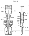
- a technique shown in Fig. 18 has been proposed (see JP2002-78798A).
- the interior of a main body of a container syringe 740 which also functions as a container, is sealed liquidtightly with two rubber stoppers of front-end 700 and back-end 710, and a drug solution is housed therein.
- a nozzle 761 of a nozzle head member 760 is provided, and an attachment part 771 of a penetrating needle member 770 is engaged in the nozzle 761.
- a liquid drug such as a resolvent
- a vial having a powder preparation or the like housed therein there is no possibility that a drug solution containing scraps of a rubber plug is injected to a body of a patient.
- the penetrating member 770 and the injection needle connecting part 761 of the nozzle head member 760 are connected only by screwing in this invention, in the case where, for example, the cartridge 750 containing the drug solution 720 without using the front-end rubber stopper 700 is subjected to autoclaving, there is such a possibility that the drug solution housed therein is leaked from the connected part.
- the drug solution 720 housed in the cartridge 750 is sealed with the front-end rubber stopper 700, but it requires such a nozzle head member 760 that forms a drug solution path 762 on an outer wall of the front-end rubber stopper upon use, so as to complicate the production process.
- a rubber material as a raw material for the rubber stoppers 700 and 710 is expensive to raise the production cost. Furthermore, due to the absence of a vial guide, a tricky operation is required on penetration to a sealing member at an opening of a vial, and coring is liable to occur in the case where it is penetrated slantwise into a rubber plug. Moreover, there is such a possibility that a tip end 772 of the penetrating member 770 is contaminated by touch with fingers or the like.
- US-A-5,584,819 describes a nested blunt/sharp injection assembly.
- a conventional sharp needle having a conventional syringe attachment adapter is nested inside a specially adapted blunt cannula which is provided with a sharp vial access tip.
- the above assembly is enclosed by a removable protective sheath, to protect the vial access tip and blunt cannula.
- the protective sheath is removed and the vial access tip is used to penetrate the elastomeric stopper which conventionally seals a medication vial, thus protecting both the blunt cannula and the sharp needle from contact with the elastomeric stopper.
- the vial access tip can be removable, so that it remains behind the medication vial after the syringe has been filled and the blunt cannula removed. The user can then selectively use either the blunt cannula or the sharp needle for the administration of the medication.
- EP 0 692 235 A1 depicts an apparatus for mixing liquid with material stored in a container having an opening sealed by a resilient plug.
- the apparatus comprises an adapter, a first and a second fitting and an injector.
- the adapter is shaped at one end to receive the container and the container plug facing towards a bore extending through the adapter.
- a first fitting having a passageway extending through it and a cannula sealed at one end of this passageway, is secured to the adapter, so that the cannula penetrates the plug of the container as it is inserted in the adapter.
- the first fitting is shaped to make a connection with a second fitting having a passageway through it.
- the second fitting is connected to an injector, which is inserted into the adapter, and thus, connected to a source of liquid with means for causing the liquid to flow into the container and mix with the material stored in it.
- EP 0 499 481 A1 describes a transfer adapter for use with a vial containing ingredients to be solved and a syringe containing a solvent.
- the distant end of a cannula for piercing a septum of a vial comprises a female receptor to receive the male exit nozzle of a syringe.
- a collar is provided between the proximal and distal ends of the cannula to prevent the adapter from passing entirely into the vial.
- This collar represents the bottom of a cannula shroud which extends below the lower end of the cannula and is provided with inwardly extending clips.
- An object of the invention is to provide such a drug solution container with a connector for communicating that can be connected at the connector for communicating to a drug container liquidtightly and removably in an ordinary sterilizing process, that causes no injury of an operator and no coring, and that promotes an operation of preparing a drug solution in a short period of time.
- the invention relates to a drug solution container with a connector for communicating containing a drug solution container having at a tip end thereof an injection needle connecting part, and a hollow connector for communicating attached to a tip end of the drug solution container; the connector for communicating containing a cylindrical guide part with a bottom capable of being slidably attached to an opening of a vial, and a hollow penetrating member provided at a center of the bottom of the guide part to penetrate the bottom; the penetrating member containing a penetrating needle at a tip end side with respect to the bottom, and a connecting part at a base end side with respect to the bottom; and the connecting part being connected to the injection needle connecting part.
- the connecting part of the penetrating member may be fitted on an outside of the injection needle connecting part, and the connecting part of the penetrating member may be adhered to the injection needle connecting part easily removably through a fragile portion.
- the connector for communicating may be easily removed from the drug solution container by rotating the connector for communicating relative to the drug solution container to remove the fragile portion.
- the connecting part of the penetrating member may be connected by screwing to the injection needle connecting part.
- a remaining part may be consecutively provided through a breaking part on the connecting part of the penetrating member at a base end side with respect to a screw forming part, the remaining part may be engaged with the injection needle connecting part, and the breaking part may be broken upon releasing the screwing of the connecting part of the penetrating member and the injection needle connecting part.
- the connecting part of the penetrating member may be connected by engaging to the injecting needle connecting part.
- a remaining part may be consecutively provided through a breaking part on a base part of the connecting part of the penetrating member, the remaining part may be engaged with the injection needle connecting part to connect the connecting part of the penetrating member to the injection needle connecting part, and the breaking part may be broken upon separating the connecting part of the penetrating member and the injection needle connecting part.
- a seal material may intervene between an inside of the connecting part of the penetrating member and a tip end of the injection needle connecting part.
- the drug solution container may comprise a barrel with an open base end having an injection needle connecting part at a tip end thereof, and a gasket inserted from the open base end of the barrel liquidtightly and slidably into the barrel.
- Fig. 1 is a vertical cross sectional view showing an embodiment of the invention, in which a fragile portion is formed with a mixture of materials forming a drug solution container and a connecting part of a penetrating member.
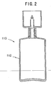
- Fig. 2 is a vertical cross sectional view showing another embodiment of the invention, in which a fragile portion is formed with a mixture of materials forming a drug solution container and a connecting part of a penetrating member, and a bottle is employed as the drug solution container.
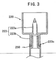
- Fig. 3 is a partial vertical cross sectional view showing still another embodiment of the invention, in which a fragile portion is formed with a mixture of materials forming a drug solution container and a connecting part of a penetrating member, and a part engaging with the fragile portion is provided on the connecting part.
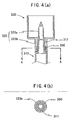
- Fig. 4 is a diagram showing a further embodiment of the invention.
- a fragile portion formed with at least one material selected from a thermoplastic elastomer, a silicone elastomer and butyl rubber is provided on an inside of a connecting part of a penetrating member.
- (a) of Fig. 4 is a partial vertical cross sectional view
- (b) of Fig. 4 is a cross sectional view on line A-A.
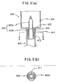
- Fig. 5 is a partial vertical cross sectional view showing a still further embodiment of the invention, in which a connector for communicating is entirely formed with at least one material selected from a thermoplastic elastomer, a silicone elastomer and butyl rubber, and an anchor is vertically provided from a backside of a bottom of a guide part.
- a connector for communicating is entirely formed with at least one material selected from a thermoplastic elastomer, a silicone elastomer and butyl rubber
- an anchor is vertically provided from a backside of a bottom of a guide part.
- Fig. 6 a partial vertical cross sectional view showing a still further embodiment of the invention, in which a fragile portion having a square ring shape formed with at least one material selected from a thermoplastic elastomer, a silicone elastomer and butyl rubber is provided on a base end of a connector for communicating.
- a) of Fig. 6 is a partial vertical cross sectional view
- (b) of Fig. 6 is a cross sectional view on line C-C.
- Fig. 7 is a partial vertical cross sectional view showing a still further embodiment of the invention, in which a connector for communicating and a drug solution container are connected by screwing.
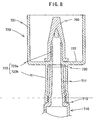
- Fig. 8 is a partial vertical cross sectional view showing a still further embodiment of the invention, in which a connector for communicating and a drug solution container are connected by screwing.
- Fig. 9 is a partial front view showing a still further embodiment of the invention
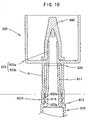
- Fig. 10 is a vertical cross sectional view of Fig. 9, in which a connector for communicating and a drug solution container are connected by screwing.
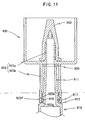
- Fig. 11 is a partial vertical cross sectional view showing a still further embodiment of the invention, in which a connector for communicating and a drug solution container are connected by screwing.
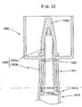
- Fig. 12 is a partial vertical cross sectional view showing a still further embodiment of the invention, in which a connector for communicating and a drug solution container are connected by engaging.
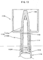
- Fig. 13 is a partial vertical cross sectional view showing a still further embodiment of the invention, in which a connector for communicating and a drug solution container are connected by engaging.
- Fig. 14 is a partial vertical cross sectional view showing a still further embodiment of the invention, in which a connector for communicating and a drug solution container are connected by engaging.
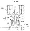
- Fig. 15 is a partial vertical cross sectional view showing a still further embodiment of the invention, in which a connector for communicating and a drug solution container are connected by screwing.
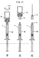
- Figs. 16 and 17 are cross sectional views showing the use of the drug solution container with a connector for communicating according to the invention.
- blocking means such a phenomenon that a thermoplastic elastomer, a silicone elastomer or butyl rubber and a polyolefin are adhered to each other, and they are difficult to be released.
- a drug solution container with a connector for communicating has a drug solution container 10 having an injection needle connecting part 11 at a tip end thereof, and a hollow connector for communicating 20 provided at the tip end of the drug solution container 10.
- the connector for communicating 20 has a cylindrical guide part 21 with a bottom 22 capable of being slidably attached to an opening of a vial, and a hollow penetrating member 23 provided at a center of the bottom 22 of the guide part 21 to penetrate the bottom 22.
- the penetrating member 23 has a penetrating needle 23a at a tip end side with respect to the bottom 22, and a connecting part 23b at a base end side with respect to the bottom 22, and the connecting part 23b is connected liquidtightly to the injection needle connecting part 11.
- such a syringe type drug solution container is preferably employed that contains a barrel 12 with an open base end having an injection needle connecting part 11 at a tip end thereof, and a gasket 30 inserted from the open base end of the barrel 12 liquidtightly and slidably into the barrel 12.
- the barrel 12 is generally a cylindrical member formed with a polyolefin resin, such as polypropylene and polyethylene, and a shoulder part 13 is formed from a base end of the injection needle connecting part 11 over an outer circumference of a tip end face of the barrel.
- a fingerhold flange 14 is provided at the base end of the barrel 12.
- the gasket 30 is formed with butyl rubber, a thermoplastic elastomer or the like, and inserted from a base end of the barrel 12 liquidtightly and slidably into the barrel 12.
- An engaging means such as a female screw 31, is provided at a base end of the gasket 30, and can be screwed with a male screw 41 provided at a tip end of a plunger 40.
- the drug solution container 110 may be a bottle 112 that is formed with a flexible material, such as polyethylene and polypropylene, and can be easily deformed by pressing, as shown in Fig. 2.
- the connector for communicating 20 is generally formed with polypropylene, an ABS resin, polyethylene, a mixture of polypropylene and polyethylene, or the like, and, as described above, contains the cylindrical guide part 21 with the bottom 22 capable of being slidably attached to the opening of the vial, and the hollow penetrating member 23 provided at the center of the bottom 22 of the guide part 21 to penetrate the bottom 22, and the penetrating member 23 contains the penetrating needle 23a at the tip end side with respect to the bottom 22, and the connecting part 23b at the base end side with respect to the bottom 22.
- An interior of the connecting part 23b has luer taper and is fitted on an outside of the injection needle connecting part 11 of the drug solution container 10, and a tip end of the connecting part 23b is adhered easily removably to the shoulder part 13 of the drug solution container 10 through a fragile portion 50.
- a connector for communicating According to the configuration, upon autoclaving the drug solution container with a connector for communicating according to the invention, invasion of water from the fitting part of the injection needle connecting part 11 and the connecting part 23b can be prevented. It is preferred that the fragile portion 50 is easily removed by applying rotation to the connector for communicating 20 relative to the drug solution container 10.
- the fragile portion 50 is formed generally, for example, with a mixed material of such a material that is poor compatibility with a material for forming the drug solution container 10 but is good compatibility with a material for forming the penetrating member 23, such as a mixed material of a material forming the drug solution container 10 and a material forming the penetrating member 23.
- the fragile portion 50 is formed with a material containing a mixture of polypropylene and polyethylene as a major component, whereby the drug solution container 10 and the penetrating member 23 are weakly welded together removably through the fragile portion 50.
- the fragile portion 50 thus formed is removed accompanied with the connector for communicating 20 from the drug solution container 10 upon rotating the connector for communicating 20 with respect to the drug solution container 10.
- the fragile portion 50 is formed with a material that is poor compatibility with a material for forming the penetrating member 23 to provide a weak adhesion force therebetween
- a structure shown in Fig. 3 may be employed in that an engaging part 223c is provided at a connecting part 223b of a penetrating member 223, whereby separation of a fragile portion 250 and a connector for communicating 220 is physically suppressed.
- the fragile portions 50 and 250 may be formed by insert molding or by two-color molding.
- a fragile portion 350 formed with at least one material selected from a thermoplastic elastomer, a silicone elastomer and butyl rubber is provided on an inside of a connecting part 323b of a penetrating member 323 of a connector for communicating 320, and a drug solution container 310 and the connector for communicating 320 are connected liquidtightly and removably by blocking of an injection needle connecting part 311 and a fragile portion 350.
- the fragile portion 350 may be formed by insert molding or by two-color molding, or in alternative, it may be separately molded and then fit inside the connecting part 323b.
- a connecting part 323b of a penetrating member 323 having provided with the fragile portion 350 formed with a thermoplastic elastomer, a silicone elastomer or butyl rubber is attached by insertion to an injection needle connecting part 311 of a drug solution container 310, so as to contact the fragile portion 350 closely to the injection needle connecting part 311, and then the whole assembly is subjected to autoclaving, for example, at 115°C for 30 minutes or at 121°C for 20 minutes, which are generally employed conditions upon production of drugs, whereby a thermoplastic elastomer, a silicone elastomer or butyl rubber forming the fragile portion 350 causes blocking with the injection needle connecting part 311 which is formed with a polyolefin resin to connect the connector for communicating 320 and the drug solution container 310 liquidtightly.
- the connector for communicating 320 Upon rotating the connector for communicating 320 relative to the drug solution container 310, the
- a connecting part 423b of a penetrating member 423 of a connector for communicating 420 is entirely formed with a thermoplastic elastomer, a silicone elastomer, butyl rubber or the like, and blocking is caused at an inside of the connecting part 423b and an outside and a shoulder part 413 of an injection needle connecting part 411, so as to connect the connecting part 423b, the injection needle connecting part 411 and the shoulder part 413 liquidtightly and removably.
- An anchor 424 is vertically provided from a backside of a bottom 422 of a guide part 421 into an interior of the connecting part 423b.
- the provision of the anchor 424 prevents, upon rotating the connector for communicating 420 relative to the drug solution container 410, the connector for communicating 420 from being removed by leaving only the connecting part 423b blocked with the injection needle connecting part 411 on the drug solution container 410.
- the anchor 424 shown in Figs. 5A and 5B is constituted with two members each having a partially cylindrical shape with an arc part, an anchor having an arbitrary shape may be employed as long as it locks the backside of the bottom of the guide part with the connecting part to prevent other parts of the connector for communicating than the connecting part from being removed from the drug solution container upon rotating the connector for communicating relative to the drug solution container.
- a fragile portion 550 having a square ring shape formed with at least one material selected from a thermoplastic elastomer, a silicone elastomer and butyl rubber is provided between an end tip of a connecting part 523b of a connector for communicating 520 and a shoulder part 513 of a drug solution container 510, and the connector for communicating 520 and the drug solution container 510 are connected liquidtightly and removably by blocking of the fragile portion 550 and the shoulder part 513.
- a protrusion 523d at a base end of the connecting part 523b, whereby upon rotating the connector for communicating 520 relative to the drug solution container 510 upon use, the fragile portion 550 is prevented from being removed from the connector for communicating 520 by a rotation force, so that the fragile portion 550 is rotated accompanied with the connector for communicating 520.
- a square ring is employed as a fragile portion in this embodiment, such other rings may also be employed that can connect the connector for communicating and the syringe liquidtightly and removably by blocking.
- the protrusion may also be provided on the side of the shoulder part.
- the material of the fragile portion 350 in Fig. 4, the connecting part 423b of the penetrating member 423 in Fig. 5, and the fragile portion 550 in a square ring shape in Fig. 6 are preferably a thermoplastic elastomer, a silicone elastomer or butyl rubber, as described in the foregoing, the material is not particularly limited as long as it can seal each of the injection needle connecting parts 311, 411 and 511 liquidtightly and removably by blocking.
- a connecting part 623b of a penetrating member 623 may be connected to an injection needle connecting part 611 by screwing liquidtightly and releasably.
- the connecting part 623b of the penetrating member 623 is not directly screwed in the injection needle connecting part 611, but they are screwed each other in the following manner. That is, a cylindrical wall 611 concentrically surrounding the injection needle connecting part 611 is provided at a shoulder part 613, and a male screw on an outside of the connecting part 623b is screwed in a female screw on an inside of the cylindrical wall 615.
- the inside of the connecting part 623b and the outside of the injection needle connecting part 611 are closely in contact with each other liquidtightly.
- a male screw on an outside of a base part of an injection needle connecting part 711 of a drug solution container 710 is screwed in a female screw on an inside of a base part of a connecting part 723b of a penetrating member 723.
- a seal material 730 examples of which include an O-ring and a packing, intervenes between a bottom 722 of a guide part 721 inner than the connecting part 723b and a tip end of the injection needle connecting part 711, whereby a connector for communicating 720 is connected to the injection needle connecting part 711 liquidtightly.
- FIG. 9 Another embodiment shown in Figs. 9 and 10 is a modified example of the embodiment shown in Fig. 8, in which a retention ring part 816 protruding to the radial outward direction is provided by integral molding on an injection needle connecting part 811 of a drug container 810 over the entire circumference thereof at a base end side with respect to the male screw forming part. Furthermore, a remaining part 823f is consecutively provided through a breaking part 823e on a connecting part 823b of a penetrating member 823 at a base end side with respect to the female screw forming part.
- the breaking part 823e is a narrow and thin member provided along the circumferential direction with constant intervals.
- a claw part 823g is provided as protruding from the remaining part 823f in the radial inward direction on a part or whole circumferential direction thereof, so as to engage (lock) a base end surface of the retention ring part 816.
- the breaking part 823e is broken, and the remaining part 823f and the claw part 823g remain on the side of the injection needle connecting part 811.
- the base end surface of the claw part 823g is slanted to the tip end side in the radial inward direction. According to the configuration, upon connecting by screwing the connecting part 823b of the penetrating member 823 to the injection needle connecting part 811 of the drug solution container 810, the claw part 823g easily overstrides the retention ring part 816 from the tip end side to engage the base end surface thereof. Upon overstriding, the remaining part 823f, the claw part 823g and the like suffer elastic deformation in the radial outward direction.
- FIG. 11 Another embodiment shown in Fig. 11 is a modified example of the embodiment shown in Figs. 9 and 10, in which a retention ring part 916 is formed separately from an injection needle connecting part 911 and is engaged with a circumferential groove 917 on an outside of the injection needle connecting part 911.
- a retention ring part 1016 protruding in the radial outward direction is formed by integral molding on a base part of an injection needle connecting part 1011 of a drug solution container 1010 over the entire circumferential direction thereof.
- a claw part 1023g is provided as protruding from a base part 1023b of a penetrating member 1023 in the radial inward direction on a part or whole circumferential direction thereof, so as to engage releasably a base end surface of the retention ring part 1016.
- FIG. 13 Another embodiment shown in Fig. 13 is a modified example of the embodiment shown in Fig. 12, in which a breaking part 1123e as a narrow and thin member and a remaining part 1123f are provided on a base part of a connecting part 1123b of a penetrating member 1123 in this order toward the base end side.
- a claw part 1123g is provided as protruding from the remaining part 1123f in the radial inward direction on a part or while circumferential direction thereof, so as to engage a base end surface of a retention ring part 1116.
- FIG. 14 Another embodiment shown in Fig. 14 is a modified example of the embodiment shown in Fig. 13, in which a retention ring part 1216 is formed separately from an injection needle connecting part 1211 and is engaged with a circumferential groove 1217 on an outside of the injection needle connecting part 1211.
- FIG. 15 is a modified example of the embodiment shown in Fig. 7, in which a male screw on an outside of a cylindrical wall 1315 is screwed in a female screw on an inside of a connecting part 1323b.
- the height of the cylindrical wall 1315 is set considerably lower than an injection needle connecting part 1311, and a ring-shaped fitting part 1323h formed on the connecting part 1323b is engaged therebetween.
- a seal material 1330 is engaged with a circumferential groove 1323i between the connecting part 1323b and the fitting part 1323h, and the seal material 1330 is in contact with a tip end of the cylindrical wall 1315, whereby the connecting part 1323b is liquidtightly connected to the injection needle connecting part 1311.
- a preferred embodiment of the drug solution container with a connector for communicating according to the invention is a syringe-type drug solution container having a drug solution having been charged therein, i.e., a so-called prefilled syringe P, as shown in Fig. 16.
- a penetrating needle of the connector for communicating is sealed liquidtightly or airtightly with a cap 60 formed with butyl rubber or a thermoplastic elastomer, as shown in Fig. 1.
- the drug solution container shown in Fig. 16 is substantially the same as that shown in Fig. 1.
- a preferred embodiment of the drug solution container of the invention i.e., a prefilled syringe P having a connector for communicating 20 connected liquidtightly and removably through a fragile portion 50 and a drug solution D1 (a resolvent in this case) having been charged therein, and a vial V having a drug D2 charged therein are prepared.
- a plunger 40 is connected to a gasket 30 of the prefilled syringe P.
- the prefilled syringe is then moved in the direction of the arrow A to slide an opening V1 of the vial V along a guide part 21 of the connector for communicating 20, whereby a rubber plug V2 of the vial V is penetrated with a penetrating needle 23a as shown in Fig. 162.
- the plunger 40 is pushed in the direction of the arrow B, and thus, the drug solution D1 housed in the prefilled syringe P is injected into the vial V.
- the drug solution D1 and the drug D2 are mixed by well shaking the prefilled syringe P and the vial V in this configuration, so as to make a drug solution MD.
- a connector for communicating and a drug solution container can be liquidtightly and removably connected to each other by an ordinary sterilizing process, and an operation for preparation of a drug solution can be easily carried out in a short period of time without causing injury of an operator or coring. Furthermore, an effort to separate a metallic needle and plastic members can be omitted since no metallic needle is used.
Description
- The present invention relates to a drug solution container with a connector for communicating that contains a drug solution having been charged therein. More particularly, it relates to a drug solution container with a connector for communicating that contains a drug solution having been charged therein, and that releasably has the connector for communicating, and the connector for communicating having a penetrating needle penetrating a sealing member at an opening part of a vial, and a vial guide.
- In general, a medical drug that is difficult to maintain stability in preparation and medical benefits in the form of a drug solution has been used in such a manner that the drug is stored by housing in a vial or the like in the form of a solid preparation, a powder preparation or a freeze-dried preparation, and upon using the same, it is mixed with a resolvent using a syringe or the like to prepare a drug solution.
- For example, in the case of a solid preparation housed in a vial, a resolvent housed in a vial or an ampoule is aspirated to a syringe (in alternative, a metallic injection needle for resolution is attached to a so-called prefilled syringe having a resolvent charged therein), and a metallic injection needle of the syringe is penetrated through a rubber plug of the vial. The resolvent is injected from the syringe to the vial to mix the resolvent with the solid preparation to prepare a drug solution, and after completing the operation for preparation of the drug solution, the drug solution is again aspirated to the syringe.
- In the procedures using a syringe, however, since a metallic injection needle is necessarily used on preparation of a drug solution, there is such a possibility that an operator injured with the metallic injection needle, and in the case where the metallic injection needle is penetrated slantwise into a rubber plug of a vial, there is also such a possibility of coring of the rubber plug. Furthermore, it is more important that the operation is complicated to consume a prolonged period of time for the preparation.
- In order to solve the problems, a technique shown in Fig. 18 has been proposed (see JP2002-78798A). In this invention, the interior of a main body of a
container syringe 740, which also functions as a container, is sealed liquidtightly with two rubber stoppers of front-end 700 and back-end 710, and a drug solution is housed therein. At a front end of acartridge 750 of the syringemain body 740, anozzle 761 of anozzle head member 760 is provided, and anattachment part 771 of a penetratingneedle member 770 is engaged in thenozzle 761. - It is said according to the invention that a liquid drug, such as a resolvent, can be easily and certainly injected from the container syringe to a vial having a powder preparation or the like housed therein, and there is no possibility that a drug solution containing scraps of a rubber plug is injected to a body of a patient.
- However, because the penetrating
member 770 and the injectionneedle connecting part 761 of thenozzle head member 760 are connected only by screwing in this invention, in the case where, for example, thecartridge 750 containing thedrug solution 720 without using the front-end rubber stopper 700 is subjected to autoclaving, there is such a possibility that the drug solution housed therein is leaked from the connected part. In order to prevent the problem, thedrug solution 720 housed in thecartridge 750 is sealed with the front-end rubber stopper 700, but it requires such anozzle head member 760 that forms adrug solution path 762 on an outer wall of the front-end rubber stopper upon use, so as to complicate the production process. A rubber material as a raw material for therubber stoppers tip end 772 of the penetratingmember 770 is contaminated by touch with fingers or the like. - US-A-5,584,819 describes a nested blunt/sharp injection assembly. In this device a conventional sharp needle having a conventional syringe attachment adapter is nested inside a specially adapted blunt cannula which is provided with a sharp vial access tip. The above assembly is enclosed by a removable protective sheath, to protect the vial access tip and blunt cannula. In use, the protective sheath is removed and the vial access tip is used to penetrate the elastomeric stopper which conventionally seals a medication vial, thus protecting both the blunt cannula and the sharp needle from contact with the elastomeric stopper. The vial access tip can be removable, so that it remains behind the medication vial after the syringe has been filled and the blunt cannula removed. The user can then selectively use either the blunt cannula or the sharp needle for the administration of the medication.
- EP 0 692 235 A1 depicts an apparatus for mixing liquid with material stored in a container having an opening sealed by a resilient plug. The apparatus comprises an adapter, a first and a second fitting and an injector. The adapter is shaped at one end to receive the container and the container plug facing towards a bore extending through the adapter. At the other side of the bore, a first fitting having a passageway extending through it and a cannula sealed at one end of this passageway, is secured to the adapter, so that the cannula penetrates the plug of the container as it is inserted in the adapter. The first fitting is shaped to make a connection with a second fitting having a passageway through it. The second fitting is connected to an injector, which is inserted into the adapter, and thus, connected to a source of liquid with means for causing the liquid to flow into the container and mix with the material stored in it.
- EP 0 499 481 A1 describes a transfer adapter for use with a vial containing ingredients to be solved and a syringe containing a solvent. The distant end of a cannula for piercing a septum of a vial comprises a female receptor to receive the male exit nozzle of a syringe. Between the proximal and distal ends of the cannula a collar is provided to prevent the adapter from passing entirely into the vial. This collar represents the bottom of a cannula shroud which extends below the lower end of the cannula and is provided with inwardly extending clips.
- As a result of earnest investigations made by the inventors to solve the problems associated with the conventional techniques, the invention has been completed.
- An object of the invention is to provide such a drug solution container with a connector for communicating that can be connected at the connector for communicating to a drug container liquidtightly and removably in an ordinary sterilizing process, that causes no injury of an operator and no coring, and that promotes an operation of preparing a drug solution in a short period of time.
- The above-mentioned object and other objects of the present invention will be clarified further more in the following description, and these objects are attained by the present invention comprising the constitution mentioned below.
- The invention relates to a drug solution container with a connector for communicating containing a drug solution container having at a tip end thereof an injection needle connecting part, and a hollow connector for communicating attached to a tip end of the drug solution container; the connector for communicating containing a cylindrical guide part with a bottom capable of being slidably attached to an opening of a vial, and a hollow penetrating member provided at a center of the bottom of the guide part to penetrate the bottom; the penetrating member containing a penetrating needle at a tip end side with respect to the bottom, and a connecting part at a base end side with respect to the bottom; and the connecting part being connected to the injection needle connecting part.
- The connecting part of the penetrating member may be fitted on an outside of the injection needle connecting part, and the connecting part of the penetrating member may be adhered to the injection needle connecting part easily removably through a fragile portion.
- The connector for communicating may be easily removed from the drug solution container by rotating the connector for communicating relative to the drug solution container to remove the fragile portion.
- The connecting part of the penetrating member may be connected by screwing to the injection needle connecting part.
- A remaining part may be consecutively provided through a breaking part on the connecting part of the penetrating member at a base end side with respect to a screw forming part, the remaining part may be engaged with the injection needle connecting part, and the breaking part may be broken upon releasing the screwing of the connecting part of the penetrating member and the injection needle connecting part.
- The connecting part of the penetrating member may be connected by engaging to the injecting needle connecting part.
- A remaining part may be consecutively provided through a breaking part on a base part of the connecting part of the penetrating member, the remaining part may be engaged with the injection needle connecting part to connect the connecting part of the penetrating member to the injection needle connecting part, and the breaking part may be broken upon separating the connecting part of the penetrating member and the injection needle connecting part.
- A seal material may intervene between an inside of the connecting part of the penetrating member and a tip end of the injection needle connecting part.
- The drug solution container may comprise a barrel with an open base end having an injection needle connecting part at a tip end thereof, and a gasket inserted from the open base end of the barrel liquidtightly and slidably into the barrel.
-
- Fig. 1 is a vertical cross sectional view showing an embodiment of the invention.
- Fig. 2 is a vertical cross sectional view showing another embodiment of the invention.
- Fig. 3 is a partial vertical cross sectional view showing another embodiment of the invention.
- Fig. 4 shows another embodiment of the invention, (a) of Fig. 4 is a partial vertical cross sectional view, and (b) of Fig. 4 is a cross sectional view on line A-A.
- Fig. 5 shows another embodiment of the invention, (a) of Fig. 5 is a partial vertical cross sectional view, and (b) of Fig. 5 is a cross sectional view on line B-B.
- Fig. 6 shows another embodiment of the invention, (a) of Fig. 6 is a partial vertical cross sectional view, and (b) of Fig. 6 is a cross sectional view on line C-C.
- Fig. 7 is a partial vertical cross sectional view showing another embodiment of the invention.
- Fig. 8 is a partial vertical cross sectional view showing another embodiment of the invention.
- Fig. 9 is a partial front view showing another embodiment of the invention.
- Fig. 10 is a vertical cross sectional view of Fig. 9.
- Fig. 11 is a partial vertical cross sectional view showing another embodiment of the invention.
- Fig. 12 is a partial vertical cross sectional view showing another embodiment of the invention.
- Fig. 13 is a partial vertical cross sectional view showing another embodiment of the invention.
- Fig. 14 is a partial vertical cross sectional view showing another embodiment of the invention.
- Fig. 15 is a partial vertical cross sectional view showing another embodiment of the invention.
- Fig. 16 is a cross sectional view showing the use of the drug solution container with a connector for communicating according to the invention.
- Fig. 17 is a cross sectional view showing the use of the drug solution container with a connector for communicating according to the invention.
- Fig. 18 is a cross sectional view showing a prior art.
- Embodiments of the invention are schematically described, and Fig. 1 is a vertical cross sectional view showing an embodiment of the invention, in which a fragile portion is formed with a mixture of materials forming a drug solution container and a connecting part of a penetrating member.
- Fig. 2 is a vertical cross sectional view showing another embodiment of the invention, in which a fragile portion is formed with a mixture of materials forming a drug solution container and a connecting part of a penetrating member, and a bottle is employed as the drug solution container.
- Fig. 3 is a partial vertical cross sectional view showing still another embodiment of the invention, in which a fragile portion is formed with a mixture of materials forming a drug solution container and a connecting part of a penetrating member, and a part engaging with the fragile portion is provided on the connecting part.
- Fig. 4 is a diagram showing a further embodiment of the invention. A fragile portion formed with at least one material selected from a thermoplastic elastomer, a silicone elastomer and butyl rubber is provided on an inside of a connecting part of a penetrating member. (a) of Fig. 4 is a partial vertical cross sectional view, and (b) of Fig. 4 is a cross sectional view on line A-A.
- Fig. 5 is a partial vertical cross sectional view showing a still further embodiment of the invention, in which a connector for communicating is entirely formed with at least one material selected from a thermoplastic elastomer, a silicone elastomer and butyl rubber, and an anchor is vertically provided from a backside of a bottom of a guide part. (a) of Fig. 5 is a partial vertical cross sectional view, and (b) of Fig. 5 is a cross sectional view on line B-B.
- Fig. 6 a partial vertical cross sectional view showing a still further embodiment of the invention, in which a fragile portion having a square ring shape formed with at least one material selected from a thermoplastic elastomer, a silicone elastomer and butyl rubber is provided on a base end of a connector for communicating. (a) of Fig. 6 is a partial vertical cross sectional view, and (b) of Fig. 6 is a cross sectional view on line C-C.
- Fig. 7 is a partial vertical cross sectional view showing a still further embodiment of the invention, in which a connector for communicating and a drug solution container are connected by screwing.
- Fig. 8 is a partial vertical cross sectional view showing a still further embodiment of the invention, in which a connector for communicating and a drug solution container are connected by screwing.
- Fig. 9 is a partial front view showing a still further embodiment of the invention, and Fig. 10 is a vertical cross sectional view of Fig. 9, in which a connector for communicating and a drug solution container are connected by screwing.
- Fig. 11 is a partial vertical cross sectional view showing a still further embodiment of the invention, in which a connector for communicating and a drug solution container are connected by screwing.
- Fig. 12 is a partial vertical cross sectional view showing a still further embodiment of the invention, in which a connector for communicating and a drug solution container are connected by engaging.
- Fig. 13 is a partial vertical cross sectional view showing a still further embodiment of the invention, in which a connector for communicating and a drug solution container are connected by engaging.
- Fig. 14 is a partial vertical cross sectional view showing a still further embodiment of the invention, in which a connector for communicating and a drug solution container are connected by engaging.
- Fig. 15 is a partial vertical cross sectional view showing a still further embodiment of the invention, in which a connector for communicating and a drug solution container are connected by screwing.
- Figs. 16 and 17 are cross sectional views showing the use of the drug solution container with a connector for communicating according to the invention.
- The term "blocking" used in this specification means such a phenomenon that a thermoplastic elastomer, a silicone elastomer or butyl rubber and a polyolefin are adhered to each other, and they are difficult to be released.
- As the invention is described in detail with reference to embodiments, in an embodiment shown in Fig. 1, a drug solution container with a connector for communicating according to the invention has a
drug solution container 10 having an injectionneedle connecting part 11 at a tip end thereof, and a hollow connector for communicating 20 provided at the tip end of thedrug solution container 10. The connector for communicating 20 has acylindrical guide part 21 with a bottom 22 capable of being slidably attached to an opening of a vial, and a hollow penetratingmember 23 provided at a center of the bottom 22 of theguide part 21 to penetrate the bottom 22. The penetratingmember 23 has a penetratingneedle 23a at a tip end side with respect to the bottom 22, and a connectingpart 23b at a base end side with respect to the bottom 22, and the connectingpart 23b is connected liquidtightly to the injectionneedle connecting part 11. - As the
drug solution container 10, such a syringe type drug solution container is preferably employed that contains abarrel 12 with an open base end having an injectionneedle connecting part 11 at a tip end thereof, and agasket 30 inserted from the open base end of thebarrel 12 liquidtightly and slidably into thebarrel 12. Thebarrel 12 is generally a cylindrical member formed with a polyolefin resin, such as polypropylene and polyethylene, and ashoulder part 13 is formed from a base end of the injectionneedle connecting part 11 over an outer circumference of a tip end face of the barrel. Afingerhold flange 14 is provided at the base end of thebarrel 12. Thegasket 30 is formed with butyl rubber, a thermoplastic elastomer or the like, and inserted from a base end of thebarrel 12 liquidtightly and slidably into thebarrel 12. An engaging means, such as a female screw 31, is provided at a base end of thegasket 30, and can be screwed with amale screw 41 provided at a tip end of aplunger 40. - The
drug solution container 110 may be abottle 112 that is formed with a flexible material, such as polyethylene and polypropylene, and can be easily deformed by pressing, as shown in Fig. 2. - As the connector for communicating 20 shown in Fig. 1 is described in detail, the connector for communicating 20 is generally formed with polypropylene, an ABS resin, polyethylene, a mixture of polypropylene and polyethylene, or the like, and, as described above, contains the
cylindrical guide part 21 with the bottom 22 capable of being slidably attached to the opening of the vial, and the hollow penetratingmember 23 provided at the center of the bottom 22 of theguide part 21 to penetrate the bottom 22, and the penetratingmember 23 contains the penetratingneedle 23a at the tip end side with respect to the bottom 22, and the connectingpart 23b at the base end side with respect to the bottom 22. An interior of the connectingpart 23b has luer taper and is fitted on an outside of the injectionneedle connecting part 11 of thedrug solution container 10, and a tip end of the connectingpart 23b is adhered easily removably to theshoulder part 13 of thedrug solution container 10 through afragile portion 50. According to the configuration, upon autoclaving the drug solution container with a connector for communicating according to the invention, invasion of water from the fitting part of the injectionneedle connecting part 11 and the connectingpart 23b can be prevented. It is preferred that thefragile portion 50 is easily removed by applying rotation to the connector for communicating 20 relative to thedrug solution container 10. - The
fragile portion 50 is formed generally, for example, with a mixed material of such a material that is poor compatibility with a material for forming thedrug solution container 10 but is good compatibility with a material for forming the penetratingmember 23, such as a mixed material of a material forming thedrug solution container 10 and a material forming the penetratingmember 23. More specifically, for example, in the case where thedrug solution container 10 is formed with polypropylene as a major component, and the penetratingmember 23 is formed with polyethylene as a major component, thefragile portion 50 is formed with a material containing a mixture of polypropylene and polyethylene as a major component, whereby thedrug solution container 10 and the penetratingmember 23 are weakly welded together removably through thefragile portion 50. Thefragile portion 50 thus formed is removed accompanied with the connector for communicating 20 from thedrug solution container 10 upon rotating the connector for communicating 20 with respect to thedrug solution container 10. In the case where thefragile portion 50 is formed with a material that is poor compatibility with a material for forming the penetratingmember 23 to provide a weak adhesion force therebetween, such a structure shown in Fig. 3 may be employed in that anengaging part 223c is provided at a connectingpart 223b of a penetratingmember 223, whereby separation of afragile portion 250 and a connector for communicating 220 is physically suppressed. - The
fragile portions - In another embodiment of the invention shown in Fig. 4, a
fragile portion 350 formed with at least one material selected from a thermoplastic elastomer, a silicone elastomer and butyl rubber is provided on an inside of a connectingpart 323b of a penetratingmember 323 of a connector for communicating 320, and adrug solution container 310 and the connector for communicating 320 are connected liquidtightly and removably by blocking of an injectionneedle connecting part 311 and afragile portion 350. Thefragile portion 350 may be formed by insert molding or by two-color molding, or in alternative, it may be separately molded and then fit inside the connectingpart 323b. - A method of connecting the
fragile portion 350 to the injectionneedle connecting part 311 by blocking in the embodiment shown in Fig. 4 will be described. A connectingpart 323b of a penetratingmember 323 having provided with thefragile portion 350 formed with a thermoplastic elastomer, a silicone elastomer or butyl rubber is attached by insertion to an injectionneedle connecting part 311 of adrug solution container 310, so as to contact thefragile portion 350 closely to the injectionneedle connecting part 311, and then the whole assembly is subjected to autoclaving, for example, at 115°C for 30 minutes or at 121°C for 20 minutes, which are generally employed conditions upon production of drugs, whereby a thermoplastic elastomer, a silicone elastomer or butyl rubber forming thefragile portion 350 causes blocking with the injectionneedle connecting part 311 which is formed with a polyolefin resin to connect the connector for communicating 320 and thedrug solution container 310 liquidtightly. Upon rotating the connector for communicating 320 relative to thedrug solution container 310, thefragile portion 350 is removed from the injectionneedle connecting part 311, and as a result, the connector for communicating 320 and thedrug solution container 310 can be separated from each other. - In another embodiment of the invention shown in Fig. 5, a connecting
part 423b of a penetratingmember 423 of a connector for communicating 420 is entirely formed with a thermoplastic elastomer, a silicone elastomer, butyl rubber or the like, and blocking is caused at an inside of the connectingpart 423b and an outside and ashoulder part 413 of an injectionneedle connecting part 411, so as to connect the connectingpart 423b, the injectionneedle connecting part 411 and theshoulder part 413 liquidtightly and removably. Ananchor 424 is vertically provided from a backside of a bottom 422 of aguide part 421 into an interior of the connectingpart 423b. The provision of theanchor 424 prevents, upon rotating the connector for communicating 420 relative to thedrug solution container 410, the connector for communicating 420 from being removed by leaving only the connectingpart 423b blocked with the injectionneedle connecting part 411 on thedrug solution container 410. While theanchor 424 shown in Figs. 5A and 5B is constituted with two members each having a partially cylindrical shape with an arc part, an anchor having an arbitrary shape may be employed as long as it locks the backside of the bottom of the guide part with the connecting part to prevent other parts of the connector for communicating than the connecting part from being removed from the drug solution container upon rotating the connector for communicating relative to the drug solution container. - In another embodiment of the invention shown in Fig. 6, a
fragile portion 550 having a square ring shape formed with at least one material selected from a thermoplastic elastomer, a silicone elastomer and butyl rubber is provided between an end tip of a connectingpart 523b of a connector for communicating 520 and ashoulder part 513 of adrug solution container 510, and the connector for communicating 520 and thedrug solution container 510 are connected liquidtightly and removably by blocking of thefragile portion 550 and theshoulder part 513. Furthermore, it is preferred to provide aprotrusion 523d at a base end of the connectingpart 523b, whereby upon rotating the connector for communicating 520 relative to thedrug solution container 510 upon use, thefragile portion 550 is prevented from being removed from the connector for communicating 520 by a rotation force, so that thefragile portion 550 is rotated accompanied with the connector for communicating 520. While a square ring is employed as a fragile portion in this embodiment, such other rings may also be employed that can connect the connector for communicating and the syringe liquidtightly and removably by blocking. The protrusion may also be provided on the side of the shoulder part. - While the material of the
fragile portion 350 in Fig. 4, the connectingpart 423b of the penetratingmember 423 in Fig. 5, and thefragile portion 550 in a square ring shape in Fig. 6 are preferably a thermoplastic elastomer, a silicone elastomer or butyl rubber, as described in the foregoing, the material is not particularly limited as long as it can seal each of the injectionneedle connecting parts - As shown in Fig. 7, instead of provision of a fragile portion, a connecting
part 623b of a penetratingmember 623 may be connected to an injectionneedle connecting part 611 by screwing liquidtightly and releasably. In Fig. 7, the connectingpart 623b of the penetratingmember 623 is not directly screwed in the injectionneedle connecting part 611, but they are screwed each other in the following manner. That is, acylindrical wall 611 concentrically surrounding the injectionneedle connecting part 611 is provided at a shoulder part 613, and a male screw on an outside of the connectingpart 623b is screwed in a female screw on an inside of thecylindrical wall 615. The inside of the connectingpart 623b and the outside of the injectionneedle connecting part 611 are closely in contact with each other liquidtightly. - In another embodiment shown in Fig. 8, a male screw on an outside of a base part of an injection
needle connecting part 711 of adrug solution container 710 is screwed in a female screw on an inside of a base part of a connectingpart 723b of a penetratingmember 723. Aseal material 730, examples of which include an O-ring and a packing, intervenes between a bottom 722 of aguide part 721 inner than the connectingpart 723b and a tip end of the injectionneedle connecting part 711, whereby a connector for communicating 720 is connected to the injectionneedle connecting part 711 liquidtightly. - Another embodiment shown in Figs. 9 and 10 is a modified example of the embodiment shown in Fig. 8, in which a
retention ring part 816 protruding to the radial outward direction is provided by integral molding on an injectionneedle connecting part 811 of adrug container 810 over the entire circumference thereof at a base end side with respect to the male screw forming part. Furthermore, a remainingpart 823f is consecutively provided through a breakingpart 823e on a connectingpart 823b of a penetratingmember 823 at a base end side with respect to the female screw forming part. The breakingpart 823e is a narrow and thin member provided along the circumferential direction with constant intervals. Aclaw part 823g is provided as protruding from the remainingpart 823f in the radial inward direction on a part or whole circumferential direction thereof, so as to engage (lock) a base end surface of theretention ring part 816. According to the configuration, in the case where the connector for communicating 820 and thedrug solution container 810 are separated from each other, i.e., in the case where the screwing between the connectingpart 823b of the penetratingmember 823 and the injectionneedle connecting part 811 of thedrug solution container 810 is released, the breakingpart 823e is broken, and the remainingpart 823f and theclaw part 823g remain on the side of the injectionneedle connecting part 811. The base end surface of theclaw part 823g is slanted to the tip end side in the radial inward direction. According to the configuration, upon connecting by screwing the connectingpart 823b of the penetratingmember 823 to the injectionneedle connecting part 811 of thedrug solution container 810, theclaw part 823g easily overstrides theretention ring part 816 from the tip end side to engage the base end surface thereof. Upon overstriding, the remainingpart 823f, theclaw part 823g and the like suffer elastic deformation in the radial outward direction. - Another embodiment shown in Fig. 11 is a modified example of the embodiment shown in Figs. 9 and 10, in which a
retention ring part 916 is formed separately from an injectionneedle connecting part 911 and is engaged with acircumferential groove 917 on an outside of the injectionneedle connecting part 911. - In another embodiment shown in Fig. 12, a
retention ring part 1016 protruding in the radial outward direction is formed by integral molding on a base part of an injectionneedle connecting part 1011 of adrug solution container 1010 over the entire circumferential direction thereof. Aclaw part 1023g is provided as protruding from abase part 1023b of a penetratingmember 1023 in the radial inward direction on a part or whole circumferential direction thereof, so as to engage releasably a base end surface of theretention ring part 1016. In this embodiment, upon separating the connector for communicating 1020 and thedrug solution container 1010 from each other, such a mechanical force is applied that is to separate the connectingpart 1023b of the penetratingmember 1023 relatively from the injectionneedle connecting part 1011 of thedrug solution container 1010, whereby the base part of the connectingpart 1023b suffers elastic deformation in the radial outward direction to release the engagement of theclaw part 1023g and theretention ring part 1016. - Another embodiment shown in Fig. 13 is a modified example of the embodiment shown in Fig. 12, in which a
breaking part 1123e as a narrow and thin member and a remainingpart 1123f are provided on a base part of a connectingpart 1123b of a penetratingmember 1123 in this order toward the base end side. Aclaw part 1123g is provided as protruding from the remainingpart 1123f in the radial inward direction on a part or while circumferential direction thereof, so as to engage a base end surface of aretention ring part 1116. In this embodiment, upon separating the connector for communicating 1120 and thedrug solution container 1110 from each other, such a mechanical force is applied that is to separate the connectingpart 1123b of the penetratingmember 1123 relatively from the injectionneedle connecting part 1111 of thedrug solution container 1110, whereby the breakingpart 1123e is broken, and the remainingpart 1123f and theclaw part 1123g remain on the side of the injectionneedle connecting part 1111. - Another embodiment shown in Fig. 14 is a modified example of the embodiment shown in Fig. 13, in which a
retention ring part 1216 is formed separately from an injectionneedle connecting part 1211 and is engaged with acircumferential groove 1217 on an outside of the injectionneedle connecting part 1211. - Another embodiment shown in Fig. 15 is a modified example of the embodiment shown in Fig. 7, in which a male screw on an outside of a
cylindrical wall 1315 is screwed in a female screw on an inside of a connectingpart 1323b. The height of thecylindrical wall 1315 is set considerably lower than an injectionneedle connecting part 1311, and a ring-shapedfitting part 1323h formed on the connectingpart 1323b is engaged therebetween. Furthermore, aseal material 1330 is engaged with acircumferential groove 1323i between the connectingpart 1323b and thefitting part 1323h, and theseal material 1330 is in contact with a tip end of thecylindrical wall 1315, whereby the connectingpart 1323b is liquidtightly connected to the injectionneedle connecting part 1311. - A preferred embodiment of the drug solution container with a connector for communicating according to the invention is a syringe-type drug solution container having a drug solution having been charged therein, i.e., a so-called prefilled syringe P, as shown in Fig. 16. In this case, a penetrating needle of the connector for communicating is sealed liquidtightly or airtightly with a
cap 60 formed with butyl rubber or a thermoplastic elastomer, as shown in Fig. 1. - Next, the use of the drug solution container according to the invention will be described with reference to Figs. 16 and 17. The drug solution container shown in Fig. 16 is substantially the same as that shown in Fig. 1.
- First, a preferred embodiment of the drug solution container of the invention, i.e., a prefilled syringe P having a connector for communicating 20 connected liquidtightly and removably through a
fragile portion 50 and a drug solution D1 (a resolvent in this case) having been charged therein, and a vial V having a drug D2 charged therein are prepared. As shown in Fig. 16 ①, aplunger 40 is connected to agasket 30 of the prefilled syringe P. The prefilled syringe is then moved in the direction of the arrow A to slide an opening V1 of the vial V along aguide part 21 of the connector for communicating 20, whereby a rubber plug V2 of the vial V is penetrated with a penetratingneedle 23a as shown in Fig. 16②. Thereafter, theplunger 40 is pushed in the direction of the arrow B, and thus, the drug solution D1 housed in the prefilled syringe P is injected into the vial V. The drug solution D1 and the drug D2 are mixed by well shaking the prefilled syringe P and the vial V in this configuration, so as to make a drug solution MD. The positions of the prefilled syringe P and the vial V are vertically reversed (inverted), and then theplunger 40 is pulled in the direction of the arrow (C) to aspirate the drug solution MD into the prefilled syringe P, as shown in Fig. 16③. Thereafter, as shown in Fig. 17④, the connector for communicating 20 is rotated in the direction of the arrow (D), and thus, the connector for communicating 20 is removed from the prefilled syringe P accompanied with thefragile portion 50 as shown in Fig. 17 ⑤. Finally, as shown in Fig. 17⑥, aninjection needle 70 is attached to an injectionneedle connecting part 11 at a tip end of the prefilled syringe P, and thus, the drug solution MD can be injected to a vein or the like of a patient. - As having been clarified by the foregoing descriptions, according to the invention, a connector for communicating and a drug solution container can be liquidtightly and removably connected to each other by an ordinary sterilizing process, and an operation for preparation of a drug solution can be easily carried out in a short period of time without causing injury of an operator or coring. Furthermore, an effort to separate a metallic needle and plastic members can be omitted since no metallic needle is used.
Claims (14)
- A drug solution container (10) with a connector (20) for communicating comprising;a drug solution container (10) having at a tip end thereof an injection needle connecting part (11), anda hollow connector (20) for communicating attached to a tip end of the drug solution container (10);wherein the connector (20) for communicating comprises a cylindrical guide part (21) provided with a bottom (22) and capable of being slidably attached to an opening (V1) of a vial (V), so that it encloses the opening (V1) of the vial(V), and a hollow penetrating member (23) provided at the center of the bottom (22) of the guide part (21) to penetrate the bottom (22); and
wherein the penetrating member (23) comprises a penetrating needle (23a) at a tip end side with respect to the bottom (22), and a connecting part (23b) at a base end side with respect to the bottom (22); and
wherein the connecting part (23b) of the penetrating member (23) is fitted on an outside of the injection needle connecting part (11), characterized in that the connecting part (23b) of the penetrating member (23) is adhered to the injection needle connecting part (11) easily removably through a fragile portion (50). - A drug solution container (10) as claimed in claim 1, wherein the fragile portion (50) is formed between a tip end of the connecting part (23b) of the penetrating member (23) and a shoulder part (13) of the drug solution container (10).
- A drug solution container (10) as claimed in claim 1, wherein the fragile portion (350) is formed between an inside of the connecting part (323b) of the penetrating member (323) and an outside of the injection needle connecting part (311).
- A drug solution container (10) as claimed in one of claims 1 to 3, wherein the fragile portion (50) is formed at least with a mixed material of a material forming the drug solution container (10) and a material forming the penetrating member (23).
- A drug solution container (10) as claimed in one of claims 1 to 3, wherein the fragile portion (350) is formed with at least one material selected from a thermoplastic elastomer, a silicone elastomer and butyl rubber.
- A drug solution container (10) as claimed in one of claims 1 to 5, wherein the connector (20) for communicating is easily removed from the drug solution container (10) by rotating the connector (20) for communicating relative to the drug solution container (10) to remove the fragile portion (50).
- A drug solution container (10) as claimed in claim 1, wherein the connecting part (623b) of the penetrating member (623) is connected by screwing to the injection needle connecting part (611).
- A drug solution container (810) as claimed in claim 7, wherein a remaining part (823f) is consecutively provided through a breaking part (823e) on the connecting part (823b) of the penetrating member at a base end side with respect to a screw forming part, the remaining part (823f) is engaged with the injection needle connecting part (811), and the breaking part (823e) is broken upon releasing the screwing of the connecting part (823b) of the penetrating member (823) and the injection needle connecting part (811).
- A drug solution container (1010) as claimed in claim 1, wherein the connecting part (1023b) of the penetrating member (1023) is connected by engaging to the injecting needle connecting part (1011).
- A drug solution container (1110) as claimed in claim 9, wherein a remaining part (1123f) is consecutively provided through a breaking part (1123e) on a base part of the connecting part (1123b) of the penetrating member (1123), the remaining part (1123f) is engaged with the injection needle connecting part (1111) to connect the connecting part (1123b) of the penetrating member (1123) to the injection needle connecting part (1111), and the breaking part (1123e) is broken upon separating the connecting part (1123b) of the penetrating member (1123) and the injection needle connecting part (1111).
- A drug solution container (1310) as claimed in one of claims 1 to 10, wherein a seal material (1330) intervenes between an inside of the connecting part (1323b) of the penetrating member (1323) and a tip end of the injection needle connecting part (1311).
- A drug solution container (10) as claimed in one of claims 1 to 11, wherein the drug solution container (10) comprises a barrel (12) with an open base end having an injection needle connecting part (11) at a tip end thereof, and a gasket (30) inserted from the open base end of the barrel (12) liquidtightly and slidably into the barrel (12).
- A drug solution container (110) as claimed in one of claims 1 to 12, wherein the drug solution container (110) comprises a bottle (112) capable of being easily deformed by pressing, having an injection needle connecting part (111) at a tip end thereof.
- A drug solution container (P) as claimed in one of claims 1 to 13, wherein the drug solution container (P) has a drug solution (D1) having been charged therein.
Applications Claiming Priority (4)
| Application Number | Priority Date | Filing Date | Title |
|---|---|---|---|
| JP2002193686 | 2002-07-02 | ||
| JP2002193686 | 2002-07-02 | ||
| JP2003099935A JP4427965B2 (en) | 2002-07-02 | 2003-04-03 | Chemical container with communication means |
| JP2003099935 | 2003-04-03 |
Publications (2)
| Publication Number | Publication Date |
|---|---|
| EP1378223A1 EP1378223A1 (en) | 2004-01-07 |
| EP1378223B1 true EP1378223B1 (en) | 2006-07-19 |
Family
ID=29720919
Family Applications (1)
| Application Number | Title | Priority Date | Filing Date |
|---|---|---|---|
| EP20030014955 Expired - Fee Related EP1378223B1 (en) | 2002-07-02 | 2003-07-01 | Drug solution container with a connector for communicating |
Country Status (5)
| Country | Link |
|---|---|
| US (1) | US6901975B2 (en) |
| EP (1) | EP1378223B1 (en) |
| JP (1) | JP4427965B2 (en) |
| CA (1) | CA2433769C (en) |
| DE (1) | DE60306851T2 (en) |
Cited By (1)
| Publication number | Priority date | Publication date | Assignee | Title |
|---|---|---|---|---|
| CN110545865A (en) * | 2017-04-04 | 2019-12-06 | 尼普洛株式会社 | Syringe-type discharge device |
Families Citing this family (92)
| Publication number | Priority date | Publication date | Assignee | Title |
|---|---|---|---|---|
| US10709850B2 (en) | 2018-06-15 | 2020-07-14 | James T. Doubet | Syringe adapter for medication |
| US11090444B2 (en) | 2018-06-15 | 2021-08-17 | James T. Doubet | Syringe adapter for medication |
| US11097058B2 (en) | 2018-06-15 | 2021-08-24 | James T. Doubet | Syringe adapter for medication |
| US11337894B2 (en) | 2018-06-15 | 2022-05-24 | James T. Doubet | Syringe adapter for animal medication |
| IL114960A0 (en) | 1995-03-20 | 1995-12-08 | Medimop Medical Projects Ltd | Flow control device |
| US20080009822A1 (en) * | 2003-12-18 | 2008-01-10 | Halkey-Roberts Corporation | Needleless access vial |
| IL161660A0 (en) * | 2004-04-29 | 2004-09-27 | Medimop Medical Projects Ltd | Liquid drug delivery device |
| GB0426479D0 (en) * | 2004-12-02 | 2005-01-05 | Glaxosmithkline Biolog Sa | Novel device |
| US8540686B2 (en) * | 2005-03-02 | 2013-09-24 | Covidien Ag | Blunt tip vial access cannula |
| DK1919432T3 (en) | 2005-08-11 | 2012-01-30 | Medimop Medical Projects Ltd | Liquid Medication Transfer Devices for Safe Safe Resting Connection on Medical Vials |
| US20070068594A1 (en) * | 2005-09-26 | 2007-03-29 | Fischer Dan E | Syringe locking structures |
| ITMI20051826A1 (en) * | 2005-09-29 | 2007-03-30 | Novachem S A | KIT FOR THE PARENTERAL ADMINISTRATION OF MEDICATIONS |
| FR2898812B1 (en) * | 2006-03-24 | 2008-06-13 | Technoflex Sa | LUER CONNECTOR, MEDICAL CONNECTOR AND TRANSFER SET COMPRISING SUCH A CONNECTOR |
| WO2008057361A2 (en) * | 2006-11-02 | 2008-05-15 | Inviro Medical Devices, Ltd. | Interchangeable retractable needle syringe with safety filling cannula |
| IL182605A0 (en) | 2007-04-17 | 2007-07-24 | Medimop Medical Projects Ltd | Fluid control device with manually depressed actuator |
| JP5549048B2 (en) * | 2007-08-16 | 2014-07-16 | 味の素株式会社 | Connection structure between drug vial and prefilled syringe |
| EP2188004A4 (en) | 2007-08-21 | 2015-06-17 | Yukon Medical Llc | Vial access and injection system |
| CN101918074B (en) | 2007-09-18 | 2013-02-27 | 麦迪麦珀医疗工程有限公司 | Medicament mixing and injection apparatus |
| IL186290A0 (en) | 2007-09-25 | 2008-01-20 | Medimop Medical Projects Ltd | Liquid drug delivery devices for use with syringe having widened distal tip |
| US8639387B2 (en) * | 2007-11-02 | 2014-01-28 | Vkr Holding A/S | Method, system and device for controlling a device related to a building aperture |
| WO2009060419A2 (en) * | 2007-11-08 | 2009-05-14 | Elcam Medical A.C.A..L. Ltd | Vial adaptor and manufacturing method therfor |
| WO2009146088A1 (en) * | 2008-04-01 | 2009-12-03 | Yukon Medical, Llc | Dual container fluid transfer device |
| US8382722B2 (en) | 2008-06-30 | 2013-02-26 | Covidien Lp | Blunt tip vial access cannula and method for manufacture |
| US20100016808A1 (en) * | 2008-07-17 | 2010-01-21 | Bioform Medical, Inc. | Thin-Walled Delivery System |
| EP2355770A1 (en) * | 2008-11-12 | 2011-08-17 | British Columbia Cancer Agency Branch | Vial handling and injection safety systems and connectors |
| US8556879B2 (en) * | 2008-11-25 | 2013-10-15 | Jms Co., Ltd. | Connector |
| USD641080S1 (en) | 2009-03-31 | 2011-07-05 | Medimop Medical Projects Ltd. | Medical device having syringe port with locking mechanism |
| USD630732S1 (en) | 2009-09-29 | 2011-01-11 | Medimop Medical Projects Ltd. | Vial adapter with female connector |
| JP2011072395A (en) * | 2009-09-29 | 2011-04-14 | Terumo Corp | Implement for mixing and injecting medicine into medical container |
| IL201323A0 (en) | 2009-10-01 | 2010-05-31 | Medimop Medical Projects Ltd | Fluid transfer device for assembling a vial with pre-attached female connector |
| IL202069A0 (en) | 2009-11-12 | 2010-06-16 | Medimop Medical Projects Ltd | Fluid transfer device with sealing arrangement |
| IL202070A0 (en) | 2009-11-12 | 2010-06-16 | Medimop Medical Projects Ltd | Inline liquid drug medical device |
| TW201129402A (en) * | 2009-12-16 | 2011-09-01 | Star Syringe Ltd | Syringes |
| BR112012021134B1 (en) | 2010-02-24 | 2020-01-21 | Medimop Medical Projects Ltd | fluid transfer set for use with a first vial and a second vial for reconstitution and liquid drug delivery |
| CN102781396B (en) | 2010-02-24 | 2015-01-07 | 麦迪麦珀医疗工程有限公司 | Liquid drug transfer device with vented vial adapter |
| WO2011132714A1 (en) * | 2010-04-22 | 2011-10-27 | 株式会社トクヤマデンタル | Ejection tool and filling method for filling material for ejection tool |
| USD655017S1 (en) | 2010-06-17 | 2012-02-28 | Yukon Medical, Llc | Shroud |
| USD669980S1 (en) | 2010-10-15 | 2012-10-30 | Medimop Medical Projects Ltd. | Vented vial adapter |
| IL209290A0 (en) | 2010-11-14 | 2011-01-31 | Medimop Medical Projects Ltd | Inline liquid drug medical device having rotary flow control member |
| JP5770857B2 (en) | 2010-12-16 | 2015-08-26 | ベクトン ディキンソン フランス | Drug delivery device |
| JP5670242B2 (en) * | 2011-03-29 | 2015-02-18 | テルモ株式会社 | Drug preparation tool |
| IL212420A0 (en) | 2011-04-17 | 2011-06-30 | Medimop Medical Projects Ltd | Liquid drug transfer assembly |
| WO2012166965A2 (en) * | 2011-05-31 | 2012-12-06 | Microlin, Llc | An apparatus and method for dermal delivery |
| USD681230S1 (en) | 2011-09-08 | 2013-04-30 | Yukon Medical, Llc | Shroud |
| US9125992B2 (en) | 2011-09-16 | 2015-09-08 | Melvin A. Finke | Fluid delivery device with filtration |
| US8945087B2 (en) | 2011-09-30 | 2015-02-03 | Covidien Lp | Pre-pierced IV access port |
| IL215699A0 (en) | 2011-10-11 | 2011-12-29 | Medimop Medical Projects Ltd | Liquid drug reconstitution assemblage for use with iv bag and drug vial |
| USD737436S1 (en) | 2012-02-13 | 2015-08-25 | Medimop Medical Projects Ltd. | Liquid drug reconstitution assembly |
| USD674088S1 (en) | 2012-02-13 | 2013-01-08 | Medimop Medical Projects Ltd. | Vial adapter |
| USD720451S1 (en) | 2012-02-13 | 2014-12-30 | Medimop Medical Projects Ltd. | Liquid drug transfer assembly |
| IL219065A0 (en) | 2012-04-05 | 2012-07-31 | Medimop Medical Projects Ltd | Fluid transfer device with manual operated cartridge release arrangement |
| CN102688538A (en) * | 2012-05-14 | 2012-09-26 | 中国人民解放军成都军区总医院 | Composite medicament administration method |
| CN103100128A (en) * | 2012-05-14 | 2013-05-15 | 中国人民解放军成都军区总医院 | Compound medicine administration method |
| USD769444S1 (en) | 2012-06-28 | 2016-10-18 | Yukon Medical, Llc | Adapter device |
| IL221634A0 (en) | 2012-08-26 | 2012-12-31 | Medimop Medical Projects Ltd | Universal drug vial adapter |
| IL221635A0 (en) | 2012-08-26 | 2012-12-31 | Medimop Medical Projects Ltd | Drug vial mixing and transfer device for use with iv bag and drug vial |
| EP2872100B1 (en) | 2012-09-13 | 2017-03-29 | Medimop Medical Projects Ltd | Telescopic female drug vial adapter |
| AU2013322638B2 (en) * | 2012-09-26 | 2017-09-14 | Transcoject Gmbh | Prefilled syringe |
| USD734868S1 (en) | 2012-11-27 | 2015-07-21 | Medimop Medical Projects Ltd. | Drug vial adapter with downwardly depending stopper |
| US20140257204A1 (en) * | 2013-03-05 | 2014-09-11 | Stuart Robert Lessin | Apparatus for reconstituting and dispensing drugs for topical application |
| IL225734A0 (en) | 2013-04-14 | 2013-09-30 | Medimop Medical Projects Ltd | Ready-to-use drug vial assemblages including drug vial and drug vial closure having fluid transfer member, and drug vial closure therefor |
| JP6199483B2 (en) | 2013-05-10 | 2017-09-20 | メディモップ・メディカル・プロジェクツ・リミテッド | Medical device comprising a vial adapter having an in-line dry drug module |
| USD765837S1 (en) | 2013-08-07 | 2016-09-06 | Medimop Medical Projects Ltd. | Liquid transfer device with integral vial adapter |
| USD767124S1 (en) | 2013-08-07 | 2016-09-20 | Medimop Medical Projects Ltd. | Liquid transfer device with integral vial adapter |
| CN205626622U (en) | 2013-08-07 | 2016-10-12 | 麦迪麦珀医疗工程有限公司 | Liquid transfer device that is used together with infusion container |
| EP2862587A1 (en) | 2013-10-15 | 2015-04-22 | Becton Dickinson France | Tip cap assembly for closing an injection system |
| USD757933S1 (en) | 2014-09-11 | 2016-05-31 | Medimop Medical Projects Ltd. | Dual vial adapter assemblage |
| WO2016110838A1 (en) | 2015-01-05 | 2016-07-14 | Medimop Medical Projects Ltd | Dual vial adapter assemblages with quick release drug vial adapter for ensuring correct usage |
| KR102507581B1 (en) * | 2015-01-19 | 2023-03-08 | 가부시끼가이샤 제이엠에스 | Medical body fluid injector |
| FR3031668A1 (en) * | 2015-01-20 | 2016-07-22 | Philippe Perovitch | DEVICE FOR DELIVERY OF ACTIVE PRINCIPLE BY PERMUCOSAL MOUTH. |
| CN113143759B (en) | 2015-07-16 | 2024-01-30 | 西部制药服务以色列有限公司 | Liquid drug transfer device for secure telescopic snap-fit on an injection vial |
| USD801522S1 (en) | 2015-11-09 | 2017-10-31 | Medimop Medical Projects Ltd. | Fluid transfer assembly |
| CN108366905A (en) | 2015-11-25 | 2018-08-03 | 西部制药服务以色列有限公司 | Include double bottle commutator components of the vial adapter of the inlet valve with automatic-sealed |
| BE1023649B1 (en) * | 2015-12-03 | 2017-06-06 | Trasis S.A. | PERFORATING NEEDLE FOR FLASK WITH SEPTUM |
| IL245803A0 (en) | 2016-05-24 | 2016-08-31 | West Pharma Services Il Ltd | Dual vial adapter assemblages including vented drug vial adapter and vented liquid vial adapter |
| IL245800A0 (en) | 2016-05-24 | 2016-08-31 | West Pharma Services Il Ltd | Dual vial adapter assemblages including identical twin vial adapters |
| IL246073A0 (en) | 2016-06-06 | 2016-08-31 | West Pharma Services Il Ltd | Fluid transfer devices for use with drug pump cartridge having slidable driving plunger |
| IL247376A0 (en) | 2016-08-21 | 2016-12-29 | Medimop Medical Projects Ltd | Syringe assembly |
| USD832430S1 (en) | 2016-11-15 | 2018-10-30 | West Pharma. Services IL, Ltd. | Dual vial adapter assemblage |
| IL249408A0 (en) | 2016-12-06 | 2017-03-30 | Medimop Medical Projects Ltd | Liquid transfer device for use with infusion liquid container and pincers-like hand tool for use therewith for releasing intact drug vial therefrom |
| US10532165B2 (en) | 2017-01-30 | 2020-01-14 | Medtronic Minimed, Inc. | Fluid reservoir and systems for filling a fluid reservoir of a fluid infusion device |
| US10500135B2 (en) * | 2017-01-30 | 2019-12-10 | Medtronic Minimed, Inc. | Fluid reservoir and systems for filling a fluid reservoir of a fluid infusion device |
| IL251458A0 (en) | 2017-03-29 | 2017-06-29 | Medimop Medical Projects Ltd | User actuated liquid drug transfer devices for use in ready-to-use (rtu) liquid drug transfer assemblages |
| IL254802A0 (en) | 2017-09-29 | 2017-12-31 | Medimop Medical Projects Ltd | Dual vial adapter assemblages with twin vented female vial adapters |
| USD890925S1 (en) | 2018-06-15 | 2020-07-21 | James T. Doubet | Syringe adapter for medication |
| US20190388625A1 (en) | 2018-06-15 | 2019-12-26 | James T. Doubet | Syringe adapter for medication |
| JP1630477S (en) | 2018-07-06 | 2019-05-07 | ||
| USD923812S1 (en) | 2019-01-16 | 2021-06-29 | West Pharma. Services IL, Ltd. | Medication mixing apparatus |
| JP1648075S (en) | 2019-01-17 | 2019-12-16 | ||
| JP7101900B2 (en) | 2019-01-31 | 2022-07-15 | ウェスト・ファーマ・サービシーズ・アイエル・リミテッド | Liquid transfer device |
| IL277446B2 (en) | 2019-04-30 | 2024-02-01 | West Pharma Services Il Ltd | Liquid transfer device with dual lumen iv spike |
| USD956958S1 (en) | 2020-07-13 | 2022-07-05 | West Pharma. Services IL, Ltd. | Liquid transfer device |
Family Cites Families (16)
| Publication number | Priority date | Publication date | Assignee | Title |
|---|---|---|---|---|
| US4128098A (en) | 1976-12-06 | 1978-12-05 | American Hospital Supply Corporation | Valved spike transfer device |
| US5211638A (en) | 1988-01-25 | 1993-05-18 | Baxter International Inc. | Pre-slit injection site |
| DE3820204A1 (en) | 1988-06-14 | 1989-12-21 | Axel Von Brand | Device for the filtered supply and removal of liquid to or from a container, especially a bottle |
| GB9103291D0 (en) | 1991-02-15 | 1991-04-03 | Waverley Pharma Ltd | Transfer adaptor |
| EP0692235A1 (en) | 1994-07-14 | 1996-01-17 | International Medication Systems (U.K.) Ltd. | Mixing & dispensing apparatus |
| US5584819A (en) | 1995-03-13 | 1996-12-17 | Kopfer; Rudolph J. | Nested blunt/sharp injection assembly |
| US5893397A (en) * | 1996-01-12 | 1999-04-13 | Bioject Inc. | Medication vial/syringe liquid-transfer apparatus |
| US6358236B1 (en) | 1998-08-06 | 2002-03-19 | Baxter International Inc. | Device for reconstituting medicaments for injection |
| DE19909824A1 (en) | 1999-03-05 | 2000-09-07 | Vetter & Co Apotheker | Syringe for medical purposes and assembly method |
| GB9907014D0 (en) * | 1999-03-27 | 1999-05-19 | Smithkline Beecham Biolog | Novel device |
| JP4372310B2 (en) | 2000-04-10 | 2009-11-25 | ニプロ株式会社 | Adapter for mixed injection |
| JP4472137B2 (en) | 2000-09-07 | 2010-06-02 | 株式会社アルテ | Container / Syringe |
| JP4156790B2 (en) | 2000-12-07 | 2008-09-24 | テルモ株式会社 | Prefilled syringe and prefilled syringe |
| JP4156791B2 (en) | 2000-12-08 | 2008-09-24 | テルモ株式会社 | Prefilled syringe and prefilled syringe |
| US6558365B2 (en) * | 2001-01-03 | 2003-05-06 | Medimop Medical Projects, Ltd. | Fluid transfer device |
| JP3763141B2 (en) | 2001-12-28 | 2006-04-05 | ニプロ株式会社 | Syringe type chemical container |
-
2003
- 2003-04-03 JP JP2003099935A patent/JP4427965B2/en not_active Expired - Fee Related
- 2003-06-27 CA CA 2433769 patent/CA2433769C/en not_active Expired - Fee Related
- 2003-06-30 US US10/608,547 patent/US6901975B2/en not_active Expired - Fee Related
- 2003-07-01 EP EP20030014955 patent/EP1378223B1/en not_active Expired - Fee Related
- 2003-07-01 DE DE2003606851 patent/DE60306851T2/en not_active Expired - Lifetime
Cited By (2)
| Publication number | Priority date | Publication date | Assignee | Title |
|---|---|---|---|---|
| CN110545865A (en) * | 2017-04-04 | 2019-12-06 | 尼普洛株式会社 | Syringe-type discharge device |
| CN110545865B (en) * | 2017-04-04 | 2022-08-23 | 尼普洛株式会社 | Syringe-type ejection device |
Also Published As
| Publication number | Publication date |
|---|---|
| US20040039365A1 (en) | 2004-02-26 |
| DE60306851T2 (en) | 2006-11-30 |
| CA2433769C (en) | 2011-01-04 |
| JP2004081819A (en) | 2004-03-18 |
| CA2433769A1 (en) | 2004-01-02 |
| DE60306851D1 (en) | 2006-08-31 |
| EP1378223A1 (en) | 2004-01-07 |
| JP4427965B2 (en) | 2010-03-10 |
| US6901975B2 (en) | 2005-06-07 |
Similar Documents
| Publication | Publication Date | Title |
|---|---|---|
| EP1378223B1 (en) | Drug solution container with a connector for communicating | |
| EP1323446B1 (en) | Syringe-type container for liquid medicine | |
| US4084588A (en) | Parenteral drug storage device with closure piercing coupling member | |
| CA2221434C (en) | Syringe filling and delivery device | |
| AU714392B2 (en) | Syringe filling and delivery device | |
| US6196998B1 (en) | Syringe and tip cap assembly | |
| EP1592381B1 (en) | Pharmaceutical delivery systems | |
| US5718690A (en) | Hypodermic injector system and method for maintaining the sterility thereof prior to use | |
| US20020095121A1 (en) | Syringe safety device | |
| US20010000347A1 (en) | Container closure system | |
| JPH1057503A (en) | Fluid transfer device for accessing fluid from vial and ampoule, and fluid transfer method using the device | |
| JP2000237278A (en) | Plug of container of drug having means of integrally inserting spike | |
| CN112105328B (en) | Connector for connecting a medical injection device to a container | |
| WO2013083673A1 (en) | Medical device having integrated sequence control | |
| JP6486276B2 (en) | Syringe outer cylinder with puncture function, syringe with puncture function and prefilled syringe with puncture function | |
| JP5416529B2 (en) | Drug administration device and drug administration device with drug container installed | |
| EP0820779B1 (en) | Syringe filling and delivery device | |
| EP3603603A1 (en) | Female syringe and syringe kit | |
| JP3294537B2 (en) | Fluid transfer device for accessing fluid from vials and ampules and method for transferring fluid using the device | |
| CA1256343A (en) | Medicine vial adaptor for needleless injector | |
| JP2005143677A (en) | Medical fluid container equipped with communication means | |
| EP0422657A1 (en) | Apparatus for storing, mixing, and using medication | |
| RU2729640C2 (en) | Device for connection of container with container and connecting unit containing such device |
Legal Events
| Date | Code | Title | Description |
|---|---|---|---|
| PUAI | Public reference made under article 153(3) epc to a published international application that has entered the european phase |
Free format text: ORIGINAL CODE: 0009012 |
|
| AK | Designated contracting states |
Kind code of ref document: A1 Designated state(s): AT BE BG CH CY CZ DE DK EE ES FI FR GB GR HU IE IT LI LU MC NL PT RO SE SI SK TR |
|
| AX | Request for extension of the european patent |
Extension state: AL LT LV MK |
|
| 17P | Request for examination filed |
Effective date: 20040618 |
|
| AKX | Designation fees paid |
Designated state(s): DE FR GB IT |
|
| 17Q | First examination report despatched |
Effective date: 20041029 |
|
| GRAP | Despatch of communication of intention to grant a patent |
Free format text: ORIGINAL CODE: EPIDOSNIGR1 |
|
| GRAS | Grant fee paid |
Free format text: ORIGINAL CODE: EPIDOSNIGR3 |
|
| GRAA | (expected) grant |
Free format text: ORIGINAL CODE: 0009210 |
|
| AK | Designated contracting states |
Kind code of ref document: B1 Designated state(s): DE FR GB IT |
|
| REG | Reference to a national code |
Ref country code: GB Ref legal event code: FG4D |
|
| REF | Corresponds to: |
Ref document number: 60306851 Country of ref document: DE Date of ref document: 20060831 Kind code of ref document: P |
|
| ET | Fr: translation filed | ||
| PLBE | No opposition filed within time limit |
Free format text: ORIGINAL CODE: 0009261 |
|
| STAA | Information on the status of an ep patent application or granted ep patent |
Free format text: STATUS: NO OPPOSITION FILED WITHIN TIME LIMIT |
|
| 26N | No opposition filed |
Effective date: 20070420 |
|
| REG | Reference to a national code |
Ref country code: FR Ref legal event code: PLFP Year of fee payment: 14 |
|
| REG | Reference to a national code |
Ref country code: FR Ref legal event code: PLFP Year of fee payment: 15 |
|
| REG | Reference to a national code |
Ref country code: FR Ref legal event code: PLFP Year of fee payment: 16 |
|
| PGFP | Annual fee paid to national office [announced via postgrant information from national office to epo] |
Ref country code: IT Payment date: 20180724 Year of fee payment: 16 Ref country code: FR Payment date: 20180725 Year of fee payment: 16 Ref country code: DE Payment date: 20180723 Year of fee payment: 16 |
|
| PGFP | Annual fee paid to national office [announced via postgrant information from national office to epo] |
Ref country code: GB Payment date: 20180719 Year of fee payment: 16 |
|
| REG | Reference to a national code |
Ref country code: DE Ref legal event code: R119 Ref document number: 60306851 Country of ref document: DE |
|
| GBPC | Gb: european patent ceased through non-payment of renewal fee |
Effective date: 20190701 |
|
| PG25 | Lapsed in a contracting state [announced via postgrant information from national office to epo] |
Ref country code: GB Free format text: LAPSE BECAUSE OF NON-PAYMENT OF DUE FEES Effective date: 20190701 Ref country code: DE Free format text: LAPSE BECAUSE OF NON-PAYMENT OF DUE FEES Effective date: 20200201 |
|
| PG25 | Lapsed in a contracting state [announced via postgrant information from national office to epo] |
Ref country code: FR Free format text: LAPSE BECAUSE OF NON-PAYMENT OF DUE FEES Effective date: 20190731 |
|
| PG25 | Lapsed in a contracting state [announced via postgrant information from national office to epo] |
Ref country code: IT Free format text: LAPSE BECAUSE OF NON-PAYMENT OF DUE FEES Effective date: 20190701 |