EP1387218B1 - Laser beam expansion without unchanged spatial coherence - Google Patents
Laser beam expansion without unchanged spatial coherence Download PDFInfo
- Publication number
- EP1387218B1 EP1387218B1 EP03017268A EP03017268A EP1387218B1 EP 1387218 B1 EP1387218 B1 EP 1387218B1 EP 03017268 A EP03017268 A EP 03017268A EP 03017268 A EP03017268 A EP 03017268A EP 1387218 B1 EP1387218 B1 EP 1387218B1
- Authority
- EP
- European Patent Office
- Prior art keywords
- reflector
- beam splitters
- light
- distance
- plane
- Prior art date
- Legal status (The legal status is an assumption and is not a legal conclusion. Google has not performed a legal analysis and makes no representation as to the accuracy of the status listed.)
- Expired - Fee Related
Links
Images


Classifications
-
- H—ELECTRICITY
- H01—ELECTRIC ELEMENTS
- H01S—DEVICES USING THE PROCESS OF LIGHT AMPLIFICATION BY STIMULATED EMISSION OF RADIATION [LASER] TO AMPLIFY OR GENERATE LIGHT; DEVICES USING STIMULATED EMISSION OF ELECTROMAGNETIC RADIATION IN WAVE RANGES OTHER THAN OPTICAL
- H01S3/00—Lasers, i.e. devices using stimulated emission of electromagnetic radiation in the infrared, visible or ultraviolet wave range
- H01S3/10—Controlling the intensity, frequency, phase, polarisation or direction of the emitted radiation, e.g. switching, gating, modulating or demodulating
-
- G—PHYSICS
- G02—OPTICS
- G02B—OPTICAL ELEMENTS, SYSTEMS OR APPARATUS
- G02B27/00—Optical systems or apparatus not provided for by any of the groups G02B1/00 - G02B26/00, G02B30/00
- G02B27/09—Beam shaping, e.g. changing the cross-sectional area, not otherwise provided for
- G02B27/0938—Using specific optical elements
- G02B27/0977—Reflective elements
-
- G—PHYSICS
- G02—OPTICS
- G02B—OPTICAL ELEMENTS, SYSTEMS OR APPARATUS
- G02B27/00—Optical systems or apparatus not provided for by any of the groups G02B1/00 - G02B26/00, G02B30/00
- G02B27/09—Beam shaping, e.g. changing the cross-sectional area, not otherwise provided for
-
- G—PHYSICS
- G02—OPTICS
- G02B—OPTICAL ELEMENTS, SYSTEMS OR APPARATUS
- G02B27/00—Optical systems or apparatus not provided for by any of the groups G02B1/00 - G02B26/00, G02B30/00
- G02B27/09—Beam shaping, e.g. changing the cross-sectional area, not otherwise provided for
- G02B27/0905—Dividing and/or superposing multiple light beams
-
- G—PHYSICS
- G02—OPTICS
- G02B—OPTICAL ELEMENTS, SYSTEMS OR APPARATUS
- G02B27/00—Optical systems or apparatus not provided for by any of the groups G02B1/00 - G02B26/00, G02B30/00
- G02B27/10—Beam splitting or combining systems
- G02B27/1006—Beam splitting or combining systems for splitting or combining different wavelengths
- G02B27/102—Beam splitting or combining systems for splitting or combining different wavelengths for generating a colour image from monochromatic image signal sources
-
- G—PHYSICS
- G02—OPTICS
- G02B—OPTICAL ELEMENTS, SYSTEMS OR APPARATUS
- G02B27/00—Optical systems or apparatus not provided for by any of the groups G02B1/00 - G02B26/00, G02B30/00
- G02B27/10—Beam splitting or combining systems
- G02B27/106—Beam splitting or combining systems for splitting or combining a plurality of identical beams or images, e.g. image replication
-
- G—PHYSICS
- G02—OPTICS
- G02B—OPTICAL ELEMENTS, SYSTEMS OR APPARATUS
- G02B27/00—Optical systems or apparatus not provided for by any of the groups G02B1/00 - G02B26/00, G02B30/00
- G02B27/10—Beam splitting or combining systems
- G02B27/1073—Beam splitting or combining systems characterized by manufacturing or alignment methods
-
- G—PHYSICS
- G02—OPTICS
- G02B—OPTICAL ELEMENTS, SYSTEMS OR APPARATUS
- G02B27/00—Optical systems or apparatus not provided for by any of the groups G02B1/00 - G02B26/00, G02B30/00
- G02B27/10—Beam splitting or combining systems
- G02B27/14—Beam splitting or combining systems operating by reflection only
- G02B27/144—Beam splitting or combining systems operating by reflection only using partially transparent surfaces without spectral selectivity
-
- G—PHYSICS
- G02—OPTICS
- G02B—OPTICAL ELEMENTS, SYSTEMS OR APPARATUS
- G02B27/00—Optical systems or apparatus not provided for by any of the groups G02B1/00 - G02B26/00, G02B30/00
- G02B27/10—Beam splitting or combining systems
- G02B27/14—Beam splitting or combining systems operating by reflection only
- G02B27/145—Beam splitting or combining systems operating by reflection only having sequential partially reflecting surfaces
-
- G—PHYSICS
- G02—OPTICS
- G02B—OPTICAL ELEMENTS, SYSTEMS OR APPARATUS
- G02B27/00—Optical systems or apparatus not provided for by any of the groups G02B1/00 - G02B26/00, G02B30/00
- G02B27/48—Laser speckle optics
-
- G—PHYSICS
- G03—PHOTOGRAPHY; CINEMATOGRAPHY; ANALOGOUS TECHNIQUES USING WAVES OTHER THAN OPTICAL WAVES; ELECTROGRAPHY; HOLOGRAPHY
- G03F—PHOTOMECHANICAL PRODUCTION OF TEXTURED OR PATTERNED SURFACES, e.g. FOR PRINTING, FOR PROCESSING OF SEMICONDUCTOR DEVICES; MATERIALS THEREFOR; ORIGINALS THEREFOR; APPARATUS SPECIALLY ADAPTED THEREFOR
- G03F7/00—Photomechanical, e.g. photolithographic, production of textured or patterned surfaces, e.g. printing surfaces; Materials therefor, e.g. comprising photoresists; Apparatus specially adapted therefor
- G03F7/70—Microphotolithographic exposure; Apparatus therefor
- G03F7/70483—Information management; Active and passive control; Testing; Wafer monitoring, e.g. pattern monitoring
- G03F7/7055—Exposure light control in all parts of the microlithographic apparatus, e.g. pulse length control or light interruption
- G03F7/70583—Speckle reduction, e.g. coherence control or amplitude/wavefront splitting
Definitions
- the invention relates to a system and method for expanding a laser beam without expanding its spatial coherence.
- the present invention relates to a light multiplexing device for expanding light emitted by a laser source into a plurality of beams of equal intensity as claimed in the preamble of claim 1.
- a light multiplexing device for expanding light emitted by a laser source into a plurality of beams of equal intensity as claimed in the preamble of claim 1.
- Such a device is already known from US-A-5 005 969 .
- lithography In lithography, or other environments (e.g., holography), expansion of an excimer laser beam or deep UV (DUV) excimer laser beam is necessary because an illumination system field is typically much bigger than the laser beam.
- laser beams are 10 mm x 10 mm or 5 mm x 20 mm, while an illumination field may be 120 mm x 25 mm.
- the laser beam is described as having a rectangular or square cross-section, various cross-sections of light can be used.
- lithography devices use an arrangement consisting of one reflector and one partial reflector (or beam splitter) to preliminarily expand the laser beam in an optical multiplexer before expanding the preliminarily expanded beam further in other parts of the lithography tool.
- an optical projection system for expanding an emitted light from a laser without changing spatial coherence of the light, without producing speckle patterns, and that eliminates the requirement for the "staircase" partial reflectors is needed.
- US 6,275,514 relates to the manufacture of printed circuit boards using quasi-CW UV radiation.
- This document discloses a multiplication device arranged to multiplex an incoming beam having intensity l o into four output beams, each output beam having the intensity l o /4.
- the multiplication device comprises partially reflective front surface mirrors. .
- EP 1304595 A represents a prior art document according to Article 54(3) and (4) EPC and discloses a horizontal reflective multiplexer comprising a plurality of beam splitters.
- US 6,219,179 B discloses a multiplexing device for multiplexing a laser beam into a two dimensional array of exit beams, the device comprising a first optical arrangement coupled to a second optical arrangement.
- the laser beam is first multiplexed in a first direction using the first optical arrangement after which the beam is multiplexed into the second direction using the second optical arrangement.
- the multiplexing device comprises a mirror and a plurality of beam splitters.
- the partially reflecting mirrors are spatially separated in planes parallel to the mirror.
- JP60150016 A discloses a system comprising an optical element holder, a detector and piezoelectric manipulators for positioning the optical element in a beam emitted by a laser.
- the present invention achieves its aim by providing an optical projection system using a light multiplexing device comprising the feature of claim 1.
- the present invention provides a light multiplexing device comprising a reflector and a plurality of spatially separated beam splitters positioned on a same side of and parallel to the reflector.
- the multiplexer expands light emitted by a laser source into a plurality of beams having light intensity substantially equal to each other without changing a spatial coherence of light emitted by laser.
- the optical system further comprises an illuminating optical system that focuses each of the plural beams and a projection optical system that projects an image of a mask illuminated with light output from illuminating optical system onto a substrate.
- a laser beam is expanded without changing its spatial coherence and without producing speckle patterns through the use of uniform partial reflectors that are much easier to manufacture and produce than "staircase" beam splitters.
- Another advantage is that it is less critical that the laser beam be accurately aligned with respect to beam splitters, which is critical in the previous devices.
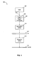
- FIG. 1 depicts an optical system according to an embodiment of the invention.
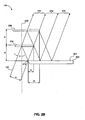
- FIGs. 2A-2B depict optical multiplexer elements and light travel within a portion of the optical system in FIG. 1 , according to embodiments of the present invention.
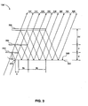
- FIG. 3 depicts optical multiplexer elements and light travel within a portion of the optical system in FIG. 1 , according to an embodiment of the present invention.
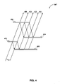
- FIG. 4 depicts optical multiplexer elements and light travel within a portion of the optical system in FIG. 1 , according to an embodiment of the present invention.
- FIG. 5 depicts an adjustment system and multiplexer elements within a portion of the optical system in FIG. 1 , according to an embodiment of the present invention.
- FIG. 1 A system 100 for expanding light 102 emitted from a laser 104 without changing spatial coherence of the light 102 and that substantially eliminates speckle patterns is shown in FIG. 1 .
- the laser 104 can be an excimer or deep UV excimer laser.
- the light 102 is received by a multiplexer 106 in a beam conditioner 108.
- the beam conditioner 108 outputs light to illumination optics 110, which in turn transmits light through a mask or reticle 112 onto a substrate 116 via projection optics 114.
- illumination optics 110 which in turn transmits light through a mask or reticle 112 onto a substrate 116 via projection optics 114.
- One embodiment for this system can be a lithography system, or the like.
- Another embodiment can be a holography system.
- multiplexer 106 can be a pre-expansion system or first expansion system that expands the light about four to six times, while further expansion can be carried out by other optics in system 100.
- pre-expansion system 106 speckle and other problems related to conventional expansion system can be substantially eliminated.
- the multiplexer 106 comprises a reflector 200 with a reflecting surface 202 that lies in a plane extending from the reflecting surface 202.
- First and second beam splitters 204 and 206 which can be 50/50 or any other ratio beam splitters having a multilayer dielectric coating than can produce expanded beams with about equal intensities, are located on a same side of the reflector 200 and lie in planes that are parallel to the plane extending from the reflecting surface 202.
- a distance d between the reflector 200 and the first beam splitter 204 is equal to a same distance d between the first beam splitter 204 and the second beam splitter 206.
- the temporal coherence length L of the laser 104 is defined by ⁇ 2 / ⁇ , where ⁇ is the spectral range of the radiation and ⁇ is the central wavelength of the laser 104.
- ⁇ is the spectral range of the radiation
- ⁇ is the central wavelength of the laser 104.
- wavelength's used in typical excimer lasers for microlithography are 248, 193, and 157 nm.
- Spectral range of radiation varies depending on the design of the lithographic tool and laser.
- the spectral range of radiation can be as small as 1 pm and as broad as 100pm.
- the range of coherence lengths L can be from .25mm to 40mm.
- the side of the width a used for calculations is based on which side of the laser beam 204 needs to be expanded.
- a light beam can be 5 mm x 20 mm.
- the width a is 5 mm and is expanded four times.
- expansion of width a can be 4 to 6 times.
- the temporal coherence length L is 20 mm, although L varies depending on spectral range, and the incident angle ⁇ is 10° (degrees).
- the light 102 emitted by the laser 104 is received at a predetermined angle ⁇ at the first beam splitter 204 that reflects a first portion of the light 102 toward the reflector 200 and transmits a second portion of the light toward the second beam splitter 206.
- the reflector 200 receives the first portion of the light 102 and reflects a third portion of the light 102 toward the second beam splitter 206.
- the second portion of the light 102 is received at the second beam splitter 206, which reflects a fourth portion of the light 102 toward the reflector 200 and transmits a fifth portion of the light 102 to produce a first output beam 212.
- the third portion of the light 102 is received at the second beam splitter 206, which reflects a sixth portion of the light 102 toward the reflector 200 and transmits a seventh portion of the light 102 to produce a second output beam 214.
- the reflector 200 receives the fourth portion of the light 102 and reflects an eighth portion of the light 102 to produce a third output beam 216.
- the reflector receives the sixth portion of the light 102 and reflects a ninth portion of the light 102 to produce a fourth output beam 218.
- the first through fourth output beams 212-218 can be equal in intensity, and are about 25% the intensity of the input beam 102. One way this can be done is using 50/50 beam splitters.
- another embodiment of the present invention includes the second beam splitter 206 being laterally shifted by 2b relatively to an edge 210 of the reflector 200 instead of the 4b lateral shift in FIG. 2A .
- the third beam of light only generates the second output 222 instead of being partially reflected and partially transmitted. Otherwise, similar to the light travel above, three output beams 220, 222, and 224 with about the same intensity are produced.
- the intensity of the output beams 220, 222, and 224 can be maintained through the use of a 66:33 beam splitter 204 and a 50:50 beam splitter 206.
- the multiplexer comprises a reflector 300 and first, second, and third beam splitters 302, 304, and 306, which can be 50/50 beam splitters.
- the relationship of the beam splitter parameters d , b , ⁇ , and L are as described above.
- the first beam splitter 302 is spaced a distance d away from a plane extending from a reflecting surface 308, the second beam splitter 304 is spaced a distance 2d , and the third beam splitter 306 is spaced a distance 4d .
- the first beam splitter 302 is laterally shifted a distance b from an edge 310 of the reflector 300, while the second beam splitter 304 is laterally shifted a distance 4b and the third beam splitter is laterally shifted a distance 10b .
- the light 102 is received at a predetermined angle ⁇ at the first beam splitter 302 that reflects a first portion of the light 102 toward the reflector 300 and transmits a second portion of the light 102 toward the second beam splitter 304.
- the second beam splitter 304 reflects a third portion of the light 102 toward the reflector 300 and transmits a fourth portion of the light 102 toward a third beam splitter 306.
- the first portion of the light 102 received at the reflector 300 is reflected as a fifth portion of the light 102 toward the second beam splitter 304.
- the beam splitter 304 reflects a sixth portion of the light 102 toward the reflector 300 and transmits a seventh portion of the light 102 toward the third beam splitter 306.
- the third portion of the light 102 is received at the reflector 300 and reflected as an eighth portion of the light 102 toward the third beam splitter 306.
- the fourth portion of the light 102 is received at the third beam splitter 306 and reflected as a ninth portion of the light 102 toward the reflector 300.
- the third beam splitter 306 transmits a tenth portion of the light 102to produce a first output beam 312.
- the reflector 300 receives the sixth portion of the light 102 and reflects an eleventh portion of the light 102 toward the third beam splitter 306.
- the third beam splitter 306 receives the seventh portion of the light 102 and reflects a twelfth portion of the light 102 toward the reflector 300 and transmits a thirteenth portion of the light 102 to produce a second output beam 314.
- the third beam splitter 306 receives the eighth portion of the light 102 and reflects a fourteenth portion of the light toward the reflector 300 and transmits a fifteenth portion of the light to produce a third output beam 316.
- the ninth portion of the light 102 is received by the reflector 300 that reflects a sixteenth portion of the light 102 to produce a fourth output beam 318.
- the eleventh portion of the light 102 is received at the third beam splitter 306 and reflected as a seventeenth portion of the light 102 toward the reflector 300 and transmitted as an eighteenth portion of the light 102 to produce a fifth output beam 320.
- the twelfth portion of the light 102 is received at the reflector 300 and reflected as a nineteenth portion of the light 102 to produce a sixth output beam 322.
- the reflector 300 receives the fourteenth portion of the light 102 and reflects a twentieth portion of the light 102 to produce a seventh output beam 324.
- the reflector 300 receives the seventeenth portion of the light 102 and reflects a twenty first portion of the light 102 to produce an eighth output beam 326. Therefore, through the arrangement shown in FIG. 3 , eight output beams 312-326 are produced each having approximately 1/8 the total intensity as the input beam 102.
- the k-th beam splitter is positioned at a distance (k-1)*d from a preceding beam splitter. Also, the first beam splitter is shifted laterally relatively to an edge of the reflector by b , where b is defined by equation (3) above. The k-th beam splitter is laterally shifted relative to the preceding beam splitter by (k-1)*3b.
- the ratio of reflection to transmission in the beam splitters can be altered slightly to account for light loss within the system 100. This is to compensate for absorption in material of the beam splitter, less than desired reflectivity, and scattering of light.
- the beam splitters are a predetermined thickness so that the lateral shift of the beam 102 inside the beam splitter body due to refraction is minimized. In lithography applications, for example, the predetermined thickness is between 1mm and 3mm. However, other thickness values can be used for other implementations of the present invention without departing from the scope of the present invention.
- the multiplexer 106" generates N times expansion of the light beam 102, as compared to 2 N times expansion of the light beam 102 in the embodiments discussed above.
- the multiplexer 106" comprises, in parallel, a first reflector 400, a first beam splitter 402, a second reflector 404, and a second beam splitter 406. Determination of the spacing between the elements is similar to that as described above.
- the light 102 is received at a predetermined angle ⁇ at a first beam splitter 402 that reflects a first portion of the light 102 toward a first reflector 400 and transmits a second portion of the light 102 toward a second beam splitter 406.
- the first portion of the light 102 received at the first reflector 400 is reflected as a third portion of the light 102 toward the second beam splitter 406.
- the second portion of the light 102 is received at the second beam splitter 406 and reflected as a fourth portion of the light 102 toward a second reflector 404 and transmitted as a fifth portion of the light 102 to produce a first output beam 408.
- the second beam splitter 406 receives the third portion of the light 102 and reflects a sixth portion of the light 102 toward the second reflector 404 and transmits a seventh portion of the light 102 to produce a second output beam 410.
- the fourth portion of the light 102 is received at the second reflector 404 and reflected as an eighth portion of the light 102 to produce a third output beam 412.
- the sixth portion of the light is received at the second reflector 404 and reflected as a ninth portion of the light to produce a fourth output beam 414.
- Each of said output beams 408-414 will have an intensity of about 25% of the incident beam 102.
- an adjusting system 500 for a multiplexer 106 is shown.
- a two beam splitter multiplexer 106 similar to that shown in FIG. 2 , can be the environment for the adjusting system 500.
- the multiplexer 106 is secured in a housing 502 that has beam splitter securing devices 504, a reflector securing device 506, and a detector securing device 508 for a detector 510.
- detection 510 can be a sectional detector (e.g., a quad detector) that more precisely determines characteristics of a detected beam.
- An adjustment device 512 is coupled to the securing devices 504, 506, and 508.
- the adjustment device 512 is also coupled to a controller 514 that controls adjustment of the securing devices 504, 506, and 508, with three degrees of freedom as shown by the arrows, based on signals received from the detector 510.
- the detector 510 In operation, the detector 510 generates a signal when the light 102 from the laser 104 falls outside of a non-detection area 516, which can result either from misalignment of the laser 104 or a distorted beam 102.
- the non-detection area 516 can be a width a of the light 102.
- the controller 514 sends a control signal to the adjustment device 512 to adjust the positioning of the beam splitters using the beam splitter securing devices 504.
- the beam splitter securing devices 504 can adjust the beam splitters in three degrees, as is shown by the arrows.
- the adjusting system 500 can be modified to accommodate any number of beam splitters and reflectors.
- the adjustment of the beam splitters or other elements within the multiplexer 106 can be done manually.
- a user would be alerted, based on a detector, that the light 102 is reaching areas of the multiplexer outside of a predetermined area. Then, the user would make mechanical adjustments to realign the light beam 102.
- Example embodiments of the present invention have been described herein. As noted elsewhere, these example embodiments have been described for illustrative purposes only, and are not limiting. Other embodiments are possible and are covered by the invention. Such embodiments will be apparent to persons skilled in the relevant art(s) based on the teachings contained herein. Thus, the breadth and scope of the present invention should not be limited by any of the above-described exemplary embodiments, but should be defined only in accordance with the following claims and their equivalence.
Description
- The invention relates to a system and method for expanding a laser beam without expanding its spatial coherence.
In particular, the present invention relates to a light multiplexing device for expanding light emitted by a laser source into a plurality of beams of equal intensity as claimed in the preamble of claim 1. Such a device is already known fromUS-A-5 005 969 . - In lithography, or other environments (e.g., holography), expansion of an excimer laser beam or deep UV (DUV) excimer laser beam is necessary because an illumination system field is typically much bigger than the laser beam. Typically, laser beams are 10 mm x 10 mm or 5 mm x 20 mm, while an illumination field may be 120 mm x 25 mm. Although the laser beam is described as having a rectangular or square cross-section, various cross-sections of light can be used. Generally, lithography devices use an arrangement consisting of one reflector and one partial reflector (or beam splitter) to preliminarily expand the laser beam in an optical multiplexer before expanding the preliminarily expanded beam further in other parts of the lithography tool. Unfortunately, expansion with typical optical devices (lenses, prisms) increases the spatial coherence of the laser and creates a speckle problem. Therefore, other optical devices can be used. The drawback of using the reflector/beam splitter arrangement is that it requires a complicated design of a "staircase" partial reflector, which consists of patches of coatings having a stepwise change in reflectivity based on predetermined parameters. Such a device is disclosed in
US-A-5 005 969 . This arrangement requires an exact match of the size and position of the laser beam and the "staircase" patch pattern. Also, a practical implementation of the "staircase" partial reflector leads to uncoated areas between the patches and the expanded beam, which results in a "zebra" pattern with dark areas cutting through bright areas of a beam cross section. Further, excimer lasers have a tendency to change the beam size and divergence over the time. - Therefore, an optical projection system for expanding an emitted light from a laser without changing spatial coherence of the light, without producing speckle patterns, and that eliminates the requirement for the "staircase" partial reflectors is needed.
-
US 6,275,514 relates to the manufacture of printed circuit boards using quasi-CW UV radiation. This document discloses a multiplication device arranged to multiplex an incoming beam having intensity lo into four output beams, each output beam having the intensity lo/4. The multiplication device comprises partially reflective front surface mirrors. . -
EP 1304595 A represents a prior art document according to Article 54(3) and (4) EPC and discloses a horizontal reflective multiplexer comprising a plurality of beam splitters. -
US 6,219,179 B discloses a multiplexing device for multiplexing a laser beam into a two dimensional array of exit beams, the device comprising a first optical arrangement coupled to a second optical arrangement. The laser beam is first multiplexed in a first direction using the first optical arrangement after which the beam is multiplexed into the second direction using the second optical arrangement. The multiplexing device comprises a mirror and a plurality of beam splitters. The partially reflecting mirrors are spatially separated in planes parallel to the mirror. -
JP60150016 A - The present invention achieves its aim by providing an optical projection system using a light multiplexing device comprising the feature of claim 1.
- The present invention provides a light multiplexing device comprising a reflector and a plurality of spatially separated beam splitters positioned on a same side of and parallel to the reflector. The multiplexer expands light emitted by a laser source into a plurality of beams having light intensity substantially equal to each other without changing a spatial coherence of light emitted by laser.
- The optical system further comprises an illuminating optical system that focuses each of the plural beams and a projection optical system that projects an image of a mask illuminated with light output from illuminating optical system onto a substrate.
- Some advantages provided by the embodiments of the invention are that a laser beam is expanded without changing its spatial coherence and without producing speckle patterns through the use of uniform partial reflectors that are much easier to manufacture and produce than "staircase" beam splitters. Another advantage is that it is less critical that the laser beam be accurately aligned with respect to beam splitters, which is critical in the previous devices.
- Further embodiments, features, and advantages of the present inventions, as well as the structure and operation of the various embodiments of the present invention, are described in detail below with reference to the accompanying drawings.
- The accompanying drawings, which are incorporated in and constitute a part of the specification, illustrate an embodiment(s) of the invention and, together with the description, explain the purpose, advantages, and principles of the invention.
-
FIG. 1 depicts an optical system according to an embodiment of the invention. -
FIGs. 2A-2B depict optical multiplexer elements and light travel within a portion of the optical system inFIG. 1 , according to embodiments of the present invention. -
FIG. 3 depicts optical multiplexer elements and light travel within a portion of the optical system inFIG. 1 , according to an embodiment of the present invention. -
FIG. 4 depicts optical multiplexer elements and light travel within a portion of the optical system inFIG. 1 , according to an embodiment of the present invention. -
FIG. 5 depicts an adjustment system and multiplexer elements within a portion of the optical system inFIG. 1 , according to an embodiment of the present invention. - In the drawings, most like reference numbers indicate the same or substantially the same elements. Furthermore, the left-most digit(s) of the reference numbers indicate the number of the drawing in which the reference number is first used.
- A
system 100 for expandinglight 102 emitted from alaser 104 without changing spatial coherence of thelight 102 and that substantially eliminates speckle patterns is shown inFIG. 1 . Thelaser 104 can be an excimer or deep UV excimer laser. Thelight 102 is received by amultiplexer 106 in abeam conditioner 108. Thebeam conditioner 108 outputs light toillumination optics 110, which in turn transmits light through a mask orreticle 112 onto asubstrate 116 viaprojection optics 114. One embodiment for this system can be a lithography system, or the like. Another embodiment can be a holography system. Although expansion is performed bymultiplexer 106,multiplexer 106 can be a pre-expansion system or first expansion system that expands the light about four to six times, while further expansion can be carried out by other optics insystem 100. By using thepre-expansion system 106, speckle and other problems related to conventional expansion system can be substantially eliminated. - Turning to
FIG. 2A , an embodiment of themultiplexer 106 is shown. Themultiplexer 106 comprises areflector 200 with a reflectingsurface 202 that lies in a plane extending from thereflecting surface 202. First andsecond beam splitters reflector 200 and lie in planes that are parallel to the plane extending from the reflectingsurface 202. A distance d between thereflector 200 and thefirst beam splitter 204 is equal to a same distance d between thefirst beam splitter 204 and thesecond beam splitter 206. The distance d is defined by an angle α, which is an angle thelight 102 intersects an axis ofsymmetry 208 of thefirst beam splitter 204, and a width a of thebeam 102 according to the following formula:
beam 102, and the temporal coherence length L of thelaser 104, are related according to the following formula:
first beam splitter 204 is laterally shifted by b and thesecond beam splitter 206 is laterally shifted by 4b relatively to anedge 210 of thereflector 200, where:
- The temporal coherence length L of the
laser 104 is defined by λ2/Δλ, where Δλ is the spectral range of the radiation and λ is the central wavelength of thelaser 104. As an example, wavelength's used in typical excimer lasers for microlithography are 248, 193, and 157 nm. Spectral range of radiation varies depending on the design of the lithographic tool and laser. The spectral range of radiation can be as small as 1 pm and as broad as 100pm. Thus, the range of coherence lengths L can be from .25mm to 40mm. - The side of the width a used for calculations is based on which side of the
laser beam 204 needs to be expanded. In one example of ranges for the different parameters a light beam can be 5 mm x 20 mm. Hence, the width a is 5 mm and is expanded four times. In other embodiments, expansion of width a can be 4 to 6 times. In this example the temporal coherence length L is 20 mm, although L varies depending on spectral range, and the incident angle α is 10° (degrees). Thus, in this example, d = 5mm/2*sin10 = 14.4 mm and b = 14.4 mm*tan(10)=2.54 mm. - In operation of the embodiment shown in
FIG. 2A , the light 102 emitted by thelaser 104 is received at a predetermined angle α at thefirst beam splitter 204 that reflects a first portion of the light 102 toward thereflector 200 and transmits a second portion of the light toward thesecond beam splitter 206. Thereflector 200 receives the first portion of the light 102 and reflects a third portion of the light 102 toward thesecond beam splitter 206. The second portion of the light 102 is received at thesecond beam splitter 206, which reflects a fourth portion of the light 102 toward thereflector 200 and transmits a fifth portion of the light 102 to produce afirst output beam 212. The third portion of the light 102 is received at thesecond beam splitter 206, which reflects a sixth portion of the light 102 toward thereflector 200 and transmits a seventh portion of the light 102 to produce asecond output beam 214. Thereflector 200 receives the fourth portion of the light 102 and reflects an eighth portion of the light 102 to produce athird output beam 216. Finally, the reflector receives the sixth portion of the light 102 and reflects a ninth portion of the light 102 to produce afourth output beam 218. The first through fourth output beams 212-218 can be equal in intensity, and are about 25% the intensity of theinput beam 102. One way this can be done is using 50/50 beam splitters. - As seen in
FIG. 2B , another embodiment of the present invention includes thesecond beam splitter 206 being laterally shifted by 2b relatively to anedge 210 of thereflector 200 instead of the 4b lateral shift inFIG. 2A . Through this arrangement of moving thesecond beam splitter 206 2b, the third beam of light only generates thesecond output 222 instead of being partially reflected and partially transmitted. Otherwise, similar to the light travel above, threeoutput beams beam splitter 204 and a 50:50beam splitter 206. - With reference now to
FIG. 3 , another embodiment of the multiplexer 106' is shown. In this embodiment, the multiplexer comprises areflector 300 and first, second, andthird beam splitters first beam splitter 302 is spaced a distance d away from a plane extending from a reflectingsurface 308, thesecond beam splitter 304 is spaced adistance 2d, and thethird beam splitter 306 is spaced a distance 4d. Also, thefirst beam splitter 302 is laterally shifted a distance b from anedge 310 of thereflector 300, while thesecond beam splitter 304 is laterally shifted adistance 4b and the third beam splitter is laterally shifted a distance 10b. - In operation of the embodiment shown in
FIG. 3 , the light 102 is received at a predetermined angle α at thefirst beam splitter 302 that reflects a first portion of the light 102 toward thereflector 300 and transmits a second portion of the light 102 toward thesecond beam splitter 304. Thesecond beam splitter 304 reflects a third portion of the light 102 toward thereflector 300 and transmits a fourth portion of the light 102 toward athird beam splitter 306. The first portion of the light 102 received at thereflector 300 is reflected as a fifth portion of the light 102 toward thesecond beam splitter 304. Thebeam splitter 304 reflects a sixth portion of the light 102 toward thereflector 300 and transmits a seventh portion of the light 102 toward thethird beam splitter 306. The third portion of the light 102 is received at thereflector 300 and reflected as an eighth portion of the light 102 toward thethird beam splitter 306. The fourth portion of the light 102 is received at thethird beam splitter 306 and reflected as a ninth portion of the light 102 toward thereflector 300. Thethird beam splitter 306 transmits a tenth portion of the light 102to produce afirst output beam 312. - The
reflector 300 receives the sixth portion of the light 102 and reflects an eleventh portion of the light 102 toward thethird beam splitter 306. Thethird beam splitter 306 receives the seventh portion of the light 102 and reflects a twelfth portion of the light 102 toward thereflector 300 and transmits a thirteenth portion of the light 102 to produce asecond output beam 314. Thethird beam splitter 306 receives the eighth portion of the light 102 and reflects a fourteenth portion of the light toward thereflector 300 and transmits a fifteenth portion of the light to produce athird output beam 316. - The ninth portion of the light 102 is received by the
reflector 300 that reflects a sixteenth portion of the light 102 to produce afourth output beam 318. The eleventh portion of the light 102 is received at thethird beam splitter 306 and reflected as a seventeenth portion of the light 102 toward thereflector 300 and transmitted as an eighteenth portion of the light 102 to produce afifth output beam 320. The twelfth portion of the light 102 is received at thereflector 300 and reflected as a nineteenth portion of the light 102 to produce asixth output beam 322. Thereflector 300 receives the fourteenth portion of the light 102 and reflects a twentieth portion of the light 102 to produce aseventh output beam 324. Finally, thereflector 300 receives the seventeenth portion of the light 102 and reflects a twenty first portion of the light 102 to produce aneighth output beam 326. Therefore, through the arrangement shown inFIG. 3 , eight output beams 312-326 are produced each having approximately 1/8 the total intensity as theinput beam 102. - Although not shown for convenience, it is to be appreciated that other embodiments of the present invention can be generalized for 2N times expansion or multiplexing of the light 102 from the
laser 104. This expansion of the light 102 is also called "multiplexing". The number of beam splitters, which can be 50/50 beam splitters or any other required for the embodiment, in each subsequent case must be equal to N. The angle α of thelight beam 102 relative to the first beam splitter in a general case is defined by equation (2) above. The beam splitters are numbered starting with the closest one to a reflector: 1, 2,...k,...N. A distance of the first beam splitter from the reflector is d, where d is defined by equation (1) above. The k-th beam splitter is positioned at a distance (k-1)*d from a preceding beam splitter. Also, the first beam splitter is shifted laterally relatively to an edge of the reflector by b, where b is defined by equation (3) above. The k-th beam splitter is laterally shifted relative to the preceding beam splitter by (k-1)*3b. - In other embodiments, the ratio of reflection to transmission in the beam splitters can be altered slightly to account for light loss within the
system 100. This is to compensate for absorption in material of the beam splitter, less than desired reflectivity, and scattering of light. Further, the beam splitters are a predetermined thickness so that the lateral shift of thebeam 102 inside the beam splitter body due to refraction is minimized. In lithography applications, for example, the predetermined thickness is between 1mm and 3mm. However, other thickness values can be used for other implementations of the present invention without departing from the scope of the present invention. - Now with reference to
FIG. 4 , another embodiment of themultiplexer 106" is shown. Thismultiplexer 106" generates N times expansion of thelight beam 102, as compared to 2N times expansion of thelight beam 102 in the embodiments discussed above. Themultiplexer 106" comprises, in parallel, afirst reflector 400, afirst beam splitter 402, asecond reflector 404, and asecond beam splitter 406. Determination of the spacing between the elements is similar to that as described above. - In operation, the light 102 is received at a predetermined angle α at a
first beam splitter 402 that reflects a first portion of the light 102 toward afirst reflector 400 and transmits a second portion of the light 102 toward asecond beam splitter 406. The first portion of the light 102 received at thefirst reflector 400 is reflected as a third portion of the light 102 toward thesecond beam splitter 406. The second portion of the light 102 is received at thesecond beam splitter 406 and reflected as a fourth portion of the light 102 toward asecond reflector 404 and transmitted as a fifth portion of the light 102 to produce afirst output beam 408. Thesecond beam splitter 406 receives the third portion of the light 102 and reflects a sixth portion of the light 102 toward thesecond reflector 404 and transmits a seventh portion of the light 102 to produce asecond output beam 410. The fourth portion of the light 102 is received at thesecond reflector 404 and reflected as an eighth portion of the light 102 to produce athird output beam 412. Finally, the sixth portion of the light is received at thesecond reflector 404 and reflected as a ninth portion of the light to produce afourth output beam 414. Each of said output beams 408-414 will have an intensity of about 25% of theincident beam 102. - Turning to
FIG. 5 , anadjusting system 500 for amultiplexer 106 is shown. Merely as an example, a twobeam splitter multiplexer 106, similar to that shown inFIG. 2 , can be the environment for theadjusting system 500. In thissystem 500, themultiplexer 106 is secured in ahousing 502 that has beamsplitter securing devices 504, areflector securing device 506, and adetector securing device 508 for adetector 510. In some embodiments,detection 510 can be a sectional detector (e.g., a quad detector) that more precisely determines characteristics of a detected beam. Anadjustment device 512 is coupled to the securingdevices adjustment device 512 is also coupled to acontroller 514 that controls adjustment of the securingdevices detector 510. - In operation, the
detector 510 generates a signal when the light 102 from thelaser 104 falls outside of anon-detection area 516, which can result either from misalignment of thelaser 104 or adistorted beam 102. Thenon-detection area 516 can be a width a of the light 102. When this signal from thedetector 510 is received at thecontroller 514, thecontroller 514 sends a control signal to theadjustment device 512 to adjust the positioning of the beam splitters using the beamsplitter securing devices 504. As described above, the beamsplitter securing devices 504 can adjust the beam splitters in three degrees, as is shown by the arrows. Once adjusted, thelight beam 102 again transmits through only thenon-detection area 516 of thedetector 510, which ensures that themultiplexer 106 will accurately produce expanded light beams. As can be appreciated, the adjustingsystem 500 can be modified to accommodate any number of beam splitters and reflectors. - It is to be appreciated that the adjustment of the beam splitters or other elements within the
multiplexer 106 can be done manually. In that embodiment, a user would be alerted, based on a detector, that the light 102 is reaching areas of the multiplexer outside of a predetermined area. Then, the user would make mechanical adjustments to realign thelight beam 102. Conclusion - Example embodiments of the present invention have been described herein. As noted elsewhere, these example embodiments have been described for illustrative purposes only, and are not limiting. Other embodiments are possible and are covered by the invention. Such embodiments will be apparent to persons skilled in the relevant art(s) based on the teachings contained herein. Thus, the breadth and scope of the present invention should not be limited by any of the above-described exemplary embodiments, but should be defined only in accordance with the following claims and their equivalence.
Claims (14)
- An optical projection system, comprising:a laser source (104);a multiplexing device (106) arranged to expand a beam of light emitted by said laser source into a plurality of beams having light intensities substantially equal to each other without changing spatial coherence comprisinga first reflector (200; 300; 400); anda plurality of beam splitters spatially separated in planes that are parallel to the plane extending from a reflecting surface of said first reflector and located on the same side of and parallel to said first reflector;an illuminating optical system (110) arranged to focus each of said plural beams; anda projection optical system (114) arranged to project an image of a mask onto a substrate when said mask is illuminated with light output from said illuminating optical system ,wherein said multiplexing device (106) is located in a housing (502) having individual securing devices (504, 506, 508) that individually secure said first reflector and each of said plurality of spatially separated beam splitters; andwherein said housing (502) further comprises an adjustment device (512, 514) that permits independent adjustment of each of said individual securing devices (504, 506, 508) based on signals from a detector (510) positioned proximate at least one of said plurality of spatially separated beam splitters.
- The system of claim 1, wherein said plurality of spatially separated beam splitters are 50/50 beam splitters.
- The system of claim 1, wherein said plurality of spatially separated beam splitters comprises two beam splitters (204, 206).
- The system of claim 3, wherein:a plane of a first one (204) of said two beam splitters is located parallel to and at a distance d from a plane extending from a reflecting surface (202) of said first reflector (200); anda plane of a second one (206) of said beam splitters is located parallel to and a at distance 2d apart from said plane of said first reflector (200);wherein d = a/(2*sin α), a is the width of said beam of light, and α is an illumination angle.
- The system of claim 3, wherein:a first one (204) of said two beam splitters is laterally shifted a distance b with to respect to an edge (210) of said first reflector (200) ; anda second one (206) of said two beam splitters is laterally shifted a distance 4b with respect to said edge (210) of said first reflector (200);wherein b = d*tan α, d is a distance from said first reflector, and α is an illumination angle.
- The system of claim 3, wherein:a first one (204) of said two beam splitters is laterally shifted a distance b with to respect to an edge (210) of said first reflector (200) ; anda second (206) one of said two beam splitters is laterally shifted a distance 2b with respect to said edge of said first reflector;wherein b = d*tan α , d is a distance from said first reflector, and α is an illumination angle.
- The system of claim 3, wherein said plural beams comprises four output beams.
- The system of claim 3, wherein said plural beams comprises three output beams.
- The system of claim 1, wherein said plurality of spatially separated beam splitters comprises three beam splitters (302, 304, 306).
- The system of claim 9, wherein:a plane of a first one (302) of said three beam splitters is located parallel to and at a distance d from a plane extending from a reflecting surface of said first reflector ;a plane of a second one (304) of said three beam splitters is located parallel to and at a distance 2d from said plane of said first reflector ; anda plane of a third one (306) of said three beam splitters is located parallel to and at a distance 4d from said plane of said first reflector ;wherein d = a/(2*sin α), a is the width of said beam of light, and α is an illumination angle.
- The system of claim 9, wherein:a first one (302) of said three beam splitters is laterally shifted a distance b with respect to an edge (310) of said first reflector (300);an edge of a second one (304) of said three beam splitters is laterally shifted a distance 4b with respect to said edge of said first reflector (300); anda third one (306) of said three beam splitters is laterally shifted a distance 10b with respect to said edge of said first reflector (300);wherein b = d*tan α, d is a distance from said first reflector, and α is an illumination angle.
- The system of claim 9, wherein said plural beams comprises eight output beams.
- The system of claim 1, wherein said multiplexing device (106) further comprises another reflector (404) parallel to said first reflector (400), wherein said another reflector is positioned between at least a first (402) and second one (406) of said beam splitters.
- The system of claim 13, wherein said plural beams comprises four output beams.
Priority Applications (1)
| Application Number | Priority Date | Filing Date | Title |
|---|---|---|---|
| EP08015487A EP1992991A3 (en) | 2002-07-31 | 2003-07-30 | System for laser beam expansion without expanding spatial coherence |
Applications Claiming Priority (2)
| Application Number | Priority Date | Filing Date | Title |
|---|---|---|---|
| US10/208,046 US6801299B2 (en) | 2002-07-31 | 2002-07-31 | System for laser beam expansion without expanding spatial coherence |
| US208046 | 2002-07-31 |
Related Child Applications (1)
| Application Number | Title | Priority Date | Filing Date |
|---|---|---|---|
| EP08015487A Division EP1992991A3 (en) | 2002-07-31 | 2003-07-30 | System for laser beam expansion without expanding spatial coherence |
Publications (2)
| Publication Number | Publication Date |
|---|---|
| EP1387218A1 EP1387218A1 (en) | 2004-02-04 |
| EP1387218B1 true EP1387218B1 (en) | 2008-09-03 |
Family
ID=30115198
Family Applications (2)
| Application Number | Title | Priority Date | Filing Date |
|---|---|---|---|
| EP08015487A Withdrawn EP1992991A3 (en) | 2002-07-31 | 2003-07-30 | System for laser beam expansion without expanding spatial coherence |
| EP03017268A Expired - Fee Related EP1387218B1 (en) | 2002-07-31 | 2003-07-30 | Laser beam expansion without unchanged spatial coherence |
Family Applications Before (1)
| Application Number | Title | Priority Date | Filing Date |
|---|---|---|---|
| EP08015487A Withdrawn EP1992991A3 (en) | 2002-07-31 | 2003-07-30 | System for laser beam expansion without expanding spatial coherence |
Country Status (8)
| Country | Link |
|---|---|
| US (2) | US6801299B2 (en) |
| EP (2) | EP1992991A3 (en) |
| JP (1) | JP3981048B2 (en) |
| KR (1) | KR100634918B1 (en) |
| CN (1) | CN100524025C (en) |
| DE (1) | DE60323303D1 (en) |
| SG (1) | SG108927A1 (en) |
| TW (1) | TWI324843B (en) |
Families Citing this family (21)
| Publication number | Priority date | Publication date | Assignee | Title |
|---|---|---|---|---|
| US6629641B2 (en) * | 2000-06-07 | 2003-10-07 | Metrologic Instruments, Inc. | Method of and system for producing images of objects using planar laser illumination beams and image detection arrays |
| US6819402B2 (en) | 2001-10-18 | 2004-11-16 | Asml Holding N.V. | System and method for laser beam expansion |
| US6801299B2 (en) * | 2002-07-31 | 2004-10-05 | Asml Holding N.V. | System for laser beam expansion without expanding spatial coherence |
| US7281807B2 (en) * | 2003-07-16 | 2007-10-16 | Honeywood Technologies, Llc | Positionable projection display devices |
| US7156522B2 (en) * | 2003-07-16 | 2007-01-02 | Plut William J | Projection-type display devices with reduced weight and size |
| GB0425419D0 (en) * | 2004-11-18 | 2004-12-22 | Sira Ltd | Interference apparatus and method and probe |
| US7244028B2 (en) * | 2004-12-14 | 2007-07-17 | Coherent, Inc. | Laser illuminated projection displays |
| US7355657B2 (en) * | 2004-12-14 | 2008-04-08 | Coherent, Inc. | Laser illuminated projection displays |
| GB0428185D0 (en) * | 2004-12-23 | 2005-01-26 | Micromass Ltd | Mass spectrometer |
| US7413311B2 (en) * | 2005-09-29 | 2008-08-19 | Coherent, Inc. | Speckle reduction in laser illuminated projection displays having a one-dimensional spatial light modulator |
| US7551359B2 (en) * | 2006-09-14 | 2009-06-23 | 3M Innovative Properties Company | Beam splitter apparatus and system |
| KR100860018B1 (en) * | 2007-07-04 | 2008-09-25 | 한국광기술원 | Speckle reduction method and apparatus |
| KR100911738B1 (en) * | 2007-08-30 | 2009-08-10 | 한국광기술원 | Speckle reduction method and apparatus |
| CN101394061B (en) * | 2008-09-23 | 2010-06-02 | 福州高意通讯有限公司 | Method for increasing output wire width of frequency doubling laser and construction thereof |
| KR101001338B1 (en) * | 2009-08-24 | 2010-12-14 | 씨엠아이텍주식회사 | Apparatus for identifying person's identity |
| WO2011115624A1 (en) * | 2010-03-19 | 2011-09-22 | Hewlett-Packard Development Company, L.P. | Optical star coupler |
| WO2015185152A1 (en) * | 2014-06-06 | 2015-12-10 | Trumpf Lasersystems For Semiconductor Manufacturing Gmbh | Device and method for monitoring a laser beam |
| JP6601098B2 (en) * | 2015-09-29 | 2019-11-06 | 株式会社Jvcケンウッド | Light source device and image projection device |
| US10078049B2 (en) * | 2016-05-18 | 2018-09-18 | The Boeing Company | Apparatus, system, and method for non-destructive testing of an object using a laser beam directed out of a plurality of apertures |
| JP6795811B2 (en) * | 2017-02-16 | 2020-12-02 | 国立大学法人埼玉大学 | Peeling substrate manufacturing method |
| CN111766711A (en) * | 2020-07-16 | 2020-10-13 | 华中科技大学 | Parallel flat plate-based equal-energy laser parallel beam splitting device, method and system |
Citations (3)
| Publication number | Priority date | Publication date | Assignee | Title |
|---|---|---|---|---|
| JPS60150016A (en) * | 1984-01-17 | 1985-08-07 | Ricoh Co Ltd | Adjusting and assembling device for lens system |
| US6219179B1 (en) * | 1999-02-05 | 2001-04-17 | Lavision Gmbh | Beam splitter device |
| EP1304595A1 (en) * | 2001-10-18 | 2003-04-23 | ASML US, Inc. | System and method for laser beam expansion |
Family Cites Families (14)
| Publication number | Priority date | Publication date | Assignee | Title |
|---|---|---|---|---|
| US2005A (en) * | 1841-03-16 | Improvement in the manner of constructing molds for casting butt-hinges | ||
| US4362361A (en) * | 1980-09-15 | 1982-12-07 | The United States Of America As Represented By The Administrator Of The National Aeronautics And Space Administration | Collimated beam manifold with the number of output beams variable at a given output angle |
| JPS6019101A (en) * | 1983-07-13 | 1985-01-31 | Hoya Corp | Beam splitter |
| US5165080A (en) * | 1987-09-11 | 1992-11-17 | British Telecommunications Public Limited Company | Optical distributor |
| JPH01287924A (en) * | 1988-03-30 | 1989-11-20 | Hitachi Ltd | Coherent control exposure device |
| JPH0778576B2 (en) * | 1988-05-17 | 1995-08-23 | 株式会社シンク・ラボラトリー | Light beam splitting method and light beam splitting modulation method |
| JPH0218518A (en) * | 1988-07-07 | 1990-01-22 | Think Lab Kk | Light beam splitter |
| US5089711A (en) * | 1990-01-19 | 1992-02-18 | California Jamar, Incorporated | Laser plasma X-ray source |
| DE4124311A1 (en) * | 1991-07-23 | 1993-01-28 | Zeiss Carl Fa | ARRANGEMENT FOR COHERENCE REDUCTION AND BEAM FORMING A LASER BEAM |
| US5224200A (en) * | 1991-11-27 | 1993-06-29 | The United States Of America As Represented By The Department Of Energy | Coherence delay augmented laser beam homogenizer |
| GB9324589D0 (en) * | 1993-11-30 | 1994-01-19 | Univ Southampton | Beam shaping device |
| KR100251052B1 (en) * | 1997-07-12 | 2000-05-01 | 윤종용 | An apparatus for separating color of light by using 2 flat plates with air gap and hybrid dichroic mirror and a method thereof |
| JP2002523905A (en) * | 1998-08-20 | 2002-07-30 | オルボテック リミテッド | Laser repetition rate multiplier |
| US6801299B2 (en) * | 2002-07-31 | 2004-10-05 | Asml Holding N.V. | System for laser beam expansion without expanding spatial coherence |
-
2002
- 2002-07-31 US US10/208,046 patent/US6801299B2/en not_active Expired - Lifetime
-
2003
- 2003-07-23 TW TW092120107A patent/TWI324843B/en not_active IP Right Cessation
- 2003-07-25 SG SG200303906A patent/SG108927A1/en unknown
- 2003-07-29 JP JP2003203218A patent/JP3981048B2/en not_active Expired - Fee Related
- 2003-07-30 DE DE60323303T patent/DE60323303D1/en not_active Expired - Lifetime
- 2003-07-30 EP EP08015487A patent/EP1992991A3/en not_active Withdrawn
- 2003-07-30 EP EP03017268A patent/EP1387218B1/en not_active Expired - Fee Related
- 2003-07-30 KR KR1020030052642A patent/KR100634918B1/en not_active IP Right Cessation
- 2003-07-31 CN CNB031523811A patent/CN100524025C/en not_active Expired - Fee Related
-
2004
- 2004-09-23 US US10/947,347 patent/US7027129B2/en not_active Expired - Fee Related
Patent Citations (3)
| Publication number | Priority date | Publication date | Assignee | Title |
|---|---|---|---|---|
| JPS60150016A (en) * | 1984-01-17 | 1985-08-07 | Ricoh Co Ltd | Adjusting and assembling device for lens system |
| US6219179B1 (en) * | 1999-02-05 | 2001-04-17 | Lavision Gmbh | Beam splitter device |
| EP1304595A1 (en) * | 2001-10-18 | 2003-04-23 | ASML US, Inc. | System and method for laser beam expansion |
Also Published As
| Publication number | Publication date |
|---|---|
| KR100634918B1 (en) | 2006-10-17 |
| EP1992991A3 (en) | 2008-11-26 |
| US20050036125A1 (en) | 2005-02-17 |
| US7027129B2 (en) | 2006-04-11 |
| JP2004128477A (en) | 2004-04-22 |
| KR20040012544A (en) | 2004-02-11 |
| US20040021842A1 (en) | 2004-02-05 |
| TW200402917A (en) | 2004-02-16 |
| CN100524025C (en) | 2009-08-05 |
| JP3981048B2 (en) | 2007-09-26 |
| SG108927A1 (en) | 2005-02-28 |
| EP1992991A2 (en) | 2008-11-19 |
| EP1387218A1 (en) | 2004-02-04 |
| US6801299B2 (en) | 2004-10-05 |
| TWI324843B (en) | 2010-05-11 |
| CN1487364A (en) | 2004-04-07 |
| DE60323303D1 (en) | 2008-10-16 |
Similar Documents
| Publication | Publication Date | Title |
|---|---|---|
| EP1387218B1 (en) | Laser beam expansion without unchanged spatial coherence | |
| US8111378B2 (en) | Exposure method and apparatus, and device production method | |
| US6160831A (en) | Wavelength calibration tool for narrow band excimer lasers | |
| KR101470769B1 (en) | Illumination system of a microlithographic projection exposure apparatus | |
| KR20010053240A (en) | Lighting system for microlithography, comprising a depolarizer | |
| EP2483720B1 (en) | Illumination optical unit for microlithography | |
| JP3175180B2 (en) | Exposure method and exposure apparatus | |
| KR100762751B1 (en) | System and method for laser beam expansion | |
| EP0127045A2 (en) | Apparatus for producing a light source of required shape | |
| KR101109354B1 (en) | System for reducing the coherence of laser radiation | |
| US5717483A (en) | Illumination optical apparatus and method and exposure apparatus using the illumination optical apparatus and method | |
| WO2010127831A1 (en) | Bandwidth narrowing module for setting a spectral bandwidth of a laser beam | |
| WO2022085146A1 (en) | Laser apparatus and manufacturing method for electronic device | |
| US20010053164A1 (en) | Laser imaging apparatus | |
| JPH1062710A (en) | Illumination optical system | |
| JP2631553B2 (en) | Laser wavelength controller | |
| KR20130069660A (en) | Illumination system of a microlithographic projection exposure apparatus | |
| CN115023656A (en) | Optical transmission unit, laser device, and method for manufacturing electronic device | |
| WO2023021622A1 (en) | Bypass device, laser apparatus, and method for manufacturing electronic device | |
| US20240030671A1 (en) | Apparatus for and method of optical component alignment | |
| JPH04250455A (en) | Arcuate illuminator | |
| JPH04252012A (en) | Arc illumination apparatus | |
| JPH04248556A (en) | Reduction stepper |
Legal Events
| Date | Code | Title | Description |
|---|---|---|---|
| PUAI | Public reference made under article 153(3) epc to a published international application that has entered the european phase |
Free format text: ORIGINAL CODE: 0009012 |
|
| AK | Designated contracting states |
Kind code of ref document: A1 Designated state(s): AT BE BG CH CY CZ DE DK EE ES FI FR GB GR HU IE IT LI LU MC NL PT RO SE SI SK TR |
|
| AX | Request for extension of the european patent |
Extension state: AL LT LV MK |
|
| RAP1 | Party data changed (applicant data changed or rights of an application transferred) |
Owner name: ASML HOLDING N.V. |
|
| 17P | Request for examination filed |
Effective date: 20040804 |
|
| AKX | Designation fees paid |
Designated state(s): DE FR GB IT NL |
|
| 17Q | First examination report despatched |
Effective date: 20041110 |
|
| 17Q | First examination report despatched |
Effective date: 20041110 |
|
| GRAP | Despatch of communication of intention to grant a patent |
Free format text: ORIGINAL CODE: EPIDOSNIGR1 |
|
| GRAS | Grant fee paid |
Free format text: ORIGINAL CODE: EPIDOSNIGR3 |
|
| GRAA | (expected) grant |
Free format text: ORIGINAL CODE: 0009210 |
|
| AK | Designated contracting states |
Kind code of ref document: B1 Designated state(s): DE FR GB IT NL |
|
| REG | Reference to a national code |
Ref country code: GB Ref legal event code: FG4D |
|
| REF | Corresponds to: |
Ref document number: 60323303 Country of ref document: DE Date of ref document: 20081016 Kind code of ref document: P |
|
| PLBE | No opposition filed within time limit |
Free format text: ORIGINAL CODE: 0009261 |
|
| STAA | Information on the status of an ep patent application or granted ep patent |
Free format text: STATUS: NO OPPOSITION FILED WITHIN TIME LIMIT |
|
| 26N | No opposition filed |
Effective date: 20090604 |
|
| GBPC | Gb: european patent ceased through non-payment of renewal fee |
Effective date: 20090730 |
|
| NLV4 | Nl: lapsed or anulled due to non-payment of the annual fee |
Effective date: 20100201 |
|
| PG25 | Lapsed in a contracting state [announced via postgrant information from national office to epo] |
Ref country code: GB Free format text: LAPSE BECAUSE OF NON-PAYMENT OF DUE FEES Effective date: 20090730 |
|
| PG25 | Lapsed in a contracting state [announced via postgrant information from national office to epo] |
Ref country code: IT Free format text: LAPSE BECAUSE OF NON-PAYMENT OF DUE FEES Effective date: 20090730 |
|
| PG25 | Lapsed in a contracting state [announced via postgrant information from national office to epo] |
Ref country code: NL Free format text: LAPSE BECAUSE OF NON-PAYMENT OF DUE FEES Effective date: 20100201 |
|
| REG | Reference to a national code |
Ref country code: FR Ref legal event code: PLFP Year of fee payment: 14 |
|
| PGFP | Annual fee paid to national office [announced via postgrant information from national office to epo] |
Ref country code: DE Payment date: 20160722 Year of fee payment: 14 |
|
| PGFP | Annual fee paid to national office [announced via postgrant information from national office to epo] |
Ref country code: FR Payment date: 20160721 Year of fee payment: 14 |
|
| REG | Reference to a national code |
Ref country code: DE Ref legal event code: R119 Ref document number: 60323303 Country of ref document: DE |
|
| REG | Reference to a national code |
Ref country code: FR Ref legal event code: ST Effective date: 20180330 |
|
| PG25 | Lapsed in a contracting state [announced via postgrant information from national office to epo] |
Ref country code: DE Free format text: LAPSE BECAUSE OF NON-PAYMENT OF DUE FEES Effective date: 20180201 |
|
| PG25 | Lapsed in a contracting state [announced via postgrant information from national office to epo] |
Ref country code: FR Free format text: LAPSE BECAUSE OF NON-PAYMENT OF DUE FEES Effective date: 20170731 |