BACKGROUND OF THE INVENTION
1. Field of the Invention
The present invention relates to a folding
portable information processing apparatus and a portable
information processing apparatus having a display on each
of the inner surface and the outer surface in a folded
condition thereof.
2. Description of the Related Art
There is known a cellular telephone comprising a
folding body, a first liquid crystal display and a second
liquid crystal display, which first liquid crystal
display is arranged on an inner surface of the folding
body in a closed condition thereof and which second
liquid crystal display is arranged in a location where
information can be checked without opening the body. On
such a cellular telephone, the body is opened to enter
predetermined information from the operation section (for
example, refer to Japanese Unexamined Patent Publication
JP-A 2002-141993 (2002)).
Fig. 29 is a perspective view of another cellular
telephone 1 viewed from one side as a related art
portable information processing apparatus. Fig. 30 is a
perspective view of the cellular telephone 1 viewed from
the other side. Fig. 29 shows the cellular telephone 1
in an open condition of the body thereof. Fig. 30 shows
the cellular telephone 1 in a closed condition of the
body thereof.
The cellular telephone 1 comprises a first movable
part 2 and a second movable part 3 connected movably in
relative angular displacement by a hinge 4, from a closed
condition where the movable parts are opposed to each
other to an open condition where the areas opposed in the
closed condition are exposed to the outside. In a closed
condition where the first and second movable parts 2, 3
are opposed to each other, an operation section 5 for
entering predetermined information is provided in an area
of the second movable part 3 opposed to the first movable
part 2, and an inner display 6 is provided in an area of
the first movable part 2 opposed to the second movable
part 3.
An outer display 7 is provided in an exposed area
of the first movable part 2 and behind the inner display
6 when the cellular telephone 1 is viewed from the inner
display 6 in a closed condition where the first and
second movable parts 2, 3 opposed to each other. On the
first movable part 2 is provided an imaging section 8 on
the same side as the side where the display face of the
outer display 7 faces.
The cellular telephone 1 can display a
predetermined display content, for example an image shot
with the imaging section 8, at least on one of the inner
display and the outer display in response to
predetermined information entered from the operation
section 5.
On the side of the first movable part 2 is
provided a shutter button 9. The cellular telephone 1
has a memory in its interior. When the operator presses
the shutter button 9, an image shot with the imaging
section 8 is stored into the memory.
According to the portable information processing
apparatus, it is impossible to operate the operation
section with the enclosure of the portable information
processing apparatus folded, so that a predetermined
display content desired by the operator cannot be
displayed on the second liquid crystal display.
On the related art cellular telephone 1, only the
shutter button 9 is provided in the area exposed to the
outside in a closed condition where the first and second
movable parts 2, 3 are opposed to each other. In the
condition where the first and second movable parts 2, 3
are opposed to each other, the operation section 5 is
covered by the first movable part 2 and not exposed to
the outside. Thus the operator cannot enter
predetermined information from the operation section 5.
As a result, like the portable information processing
apparatus, a predetermined display content desired by the
operator cannot be displayed on the outer display 7.
To display a predetermined display content desired
by the operator on the outer display 7, it is necessary
to unfold the first and second movable parts 2, 3 and
enter from the operation section 5 predetermined
information on the predetermined display content to be
displayed on the outer display 7. The operation section
5 is provided facing the side opposite to the outer
display 7 with the first and second movable parts 2, 3 in
an open condition. Thus it is difficult for the operator
to enter predetermine information from the operation
section 5 while watching the outer display 7. Even in
case a predetermined display content is displayed on the
outer display 7, it is necessary to face the operation
section 5 toward the operator. On the cellular telephone
1, in order to display a predetermined display content on
the outer display 7, it is necessary to unfold the first
and second movable parts 2, 3 and enter predetermined
information on the predetermined display content with the
operation section 5 facing the operator, resulting in
cumbersome operation. In case a predetermined
information is entered with the operation section 5
facing the operator, the operator cannot watch the outer
display 7 where the predetermined display content is
provided. It is thus necessary to flip over the cellular
telephone 1 in order to check the display content on the
outer display 7. This often results in a longer set time
for displaying the display content desired by the
operator on the outer display 7.
For example, in case it is necessary to enter
predetermined information on an image as a display
content to be displayed on the outer display 7 in setting
various functions during photographing such as exposure
correction setting, ZOOM/WIDE setting, image size setting
and image quality selection while an image shot with the
imaging section 8 is displayed on the outer display 7 and
the outer display 7 is used as a camera finder, the
operator must enter information on the operation section
5 facing the side opposite to the outer display 7 and has
difficulty in entering predetermined information while
watching the outer display 7. Thus, the operator must
flip over the cellular telephone 1 and has difficulty in
entering in entering predetermined information while
watching the outer display 7, which worsens operation of
the apparatus.
SUMMARY OF THE INVENTION
An object of the invention is to provide portable
information processing apparatus featuring enhanced
operability which is capable of readily displaying a
predetermined display content on a display provided in an
area exposed to the outside in a condition where a first
movable part and a second movable part fold closed while
opposed to each other.
The invention provides a portable information
processing apparatus comprising:
According to the invention, even in a closed
condition where the first and second movable parts are
opposed to each other, the outer operation section for
entering predetermined information on the predetermined
display content displayed on the outer display provided
in the exposed area of the first and second movable parts.
Thus it is possible to enter predetermined information
from the outer operation section to display a
predetermined display content on the outer display
without placing the portable information processing
apparatus in an open condition where the areas opposed
when the first and second movable parts fold closed are
exposed to the outside.
The outer operation section is provided in an area
other than the exposed area of at least one of the first
and second movable parts whichever comes behind the outer
display in a closed condition where the first and second
movable parts are opposed to each other. Thus the outer
operation section is arranged in an area where the
operator can perform operation while watching the outer
display. The operator can enter predetermined
information from the outer operation section while
watching the outer display so that it is possible to
display a display content desired by the operator on the
outer display.
According to the invention, even in a condition
where the first and second movable parts fold closed
while opposed to each other, it is possible to enter
predetermined information from the outer operation
section and display a predetermined display content on
the outer display provided in an area exposed to the
outside in a condition where the first and second movable
parts fold closed.
The outer operation section is arranged in an area
where the operator can perform operation while watching
the outer display. The operator can enter predetermined
information with ease from the outer operation section
while watching the outer display, thus the operator can
enter predetermined information from the outer operation
section while watching a predetermined display content
displayed on the outer display. This enhances the
operability and displays a display content desired by the
operator on the outer display in a brief interval of time.
According to the invention, the operator can enter
predetermined information from the outer operation
section while watching the outer display even in a
condition where the first and second movable parts fold
closed and readily display a predetermined display
content desired by the operator on the outer display,
thereby enhancing the convenience.
In the invention it is preferable that the
portable information processing apparatus further
comprises an imaging section disposed on the exposed area,
for shooting an image in response to predetermined
information entered from one of the inner operation
section and the outer operation section, the imaging
section being provided facing the same side as the side
where the display face of the outer display faces, and
that an image shot with the imaging section is displayed
on at lease one of the inner display and the outer
display corresponding to one of the inner operation
section and the outer operation section from which the
predetermined information used to shoot an image with the
imaging section was entered.
According to the invention, the imaging section
shoots an image in response to predetermined information
entered from one of the inner operation section and the
outer operation section. In case predetermined
information is entered from the inner operation section
for shooting with the imaging section, an image shot with
the imaging section is displayed at least on the inner
display corresponding to the inner operation section. In
case predetermined information is entered from the outer
operation section for shooting with the imaging section,
an image shot with the imaging section is displayed at
least on the outer display corresponding to the outer
operation section.
The imaging section is provided facing the same
side as the side where the display face of the outer
display faces. Thus, even in case the operator takes a
picture of the operator himself/herself, he/she can take
a picture while checking the range of photographing by
the imaging section by displaying on the outer display an
image to be shot with the imaging section. Thereby the
freedom of photographing is enhanced.
In the invention it is preferable that the
portable information processing apparatus further
comprises a condition detector for detecting a closed
condition and an open condition of the first and second
movable parts, and that wherein the inner operation
section is activated and the outer operation section is
deactivated in case the first and second movable parts
are in an open condition and the inner operation section
is deactivated and the outer operation section is
activated in case the first and second movable parts are
in a closed condition.
According to the invention, the inner operation
section is activated and the outer operation section is
deactivated in case the first and second movable parts
are in an open condition, while the inner operation
section is deactivated and the outer operation section is
activated in case the first and second movable parts are
in a closed condition. It is not necessary to enter,
from the inner operation section or outer operation
section, predetermined information for determining which
of the inner operation section or outer operation section
is used to enter information. It is possible to readily
choose the inner operation section or outer operation
section from which information is entered, by simply
moving the first and second movable parts in relative
angular displacement to place the first and second
movable parts in a closed condition or open condition.
When the first and second movable parts are placed
in an open condition in order to enter predetermined
information from the inner operation section, only input
from the inner operation section is valid so that input
operation is avoided even when the outer operation
section undesirably comes in contact with another object
thus preventing malfunction. When the first and second
movable parts are placed in a closed condition in order
to enter predetermined information from the outer
operation section, only input from the outer operation
section is valid. It is thus possible to enter
predetermined information from the outer operation
section without choosing one of the inner operation
section and the outer operation section.
According to the invention, it is possible to
readily determine which of the inner operation section or
outer operation section is used to enter information only
by moving the first and second movable parts in relative
angular displacement to place the first and second
movable parts in a closed condition or open condition.
Thus it is not necessary to operate the inner operation
section or outer operation section to choose the target
operation section thus enhancing the operability.
When the first and second movable parts are placed
in an open condition, only input from the inner operation
section is valid. When the first and second movable
parts are placed in a closed condition, only input from
the outer operation section is valid. This operation is
invalid even in case, during operation in one operation
section, any finger of the operator undesirably comes in
contact with the other operation section, thus preventing
malfunction.
In the invention it is preferable that at least
one of the inner operation section and the outer
operation section includes an operation selector for
activating one of the inner operation section and the
outer operation section and deactivating the other one of
the inner operation section and the outer operation
section.
According to the invention, it is possible to
activate one of the inner operation section and the outer
operation section and deactivate the other one of the
inner operation section and the outer operation section
by way of the operation selector included by at least one
of the inner operation section and the outer operation
section. Thus it is possible to readily choose the
operation section from which predetermined information is
entered. Further, by activating only one of the inner
operation section and the outer operation section, it is
possible to prevent the other one of the inner operation
section and the outer operation section from coming in
contact with another object and triggering malfunction.
In the invention it is preferable that the
condition detector comprises:
According to the invention, in a closed condition
where the first and second movable parts are opposed to
each other or in an open condition where the areas
opposed in a closed condition are exposed to the outside,
to the discrete contact section where one set of discrete
contacts and the other set of discrete contacts formed in
the shape of comb teeth are formed in engagement while
spaced from each other in the direction of the face of a
substrate is connected the common contact section which
mutually provides electric contact with each of the
discrete contacts. It is thus readily possible to detect,
by way of the open/closed condition of the contact
section, whether the first and second movable part are in
a closed condition or open condition.
The common contact section comes in contact with a
plurality of tongues of one or the other sets of discrete
contacts having a shape of comb teeth. Even in case some
of the plurality of tongues do not come into contact with
the common contact section, the other tongues remain in
contact with the common contact section. This secures
connection between one and the other sets of discrete
contacts. Even in an imperfect contact, it is possible
to detect the closed condition and the open condition of
the first and second movable parts without fail.
According to the invention, whether the first and
second movable parts are in a closed condition or an open
condition is detected by way of open/closed condition of
the contact section. The closed condition and the open
condition are detected by way of the physical contact.
It is thus possible to fabricate a condition detector by
using a simple configuration as well as to perform
reliable detection.
The common contact section connects to the
plurality of tongues of one and the other sets of
discrete contacts having a shape of comb teeth. This
secures detection of the closed condition and the open
condition of the first and second movable parts even in
an imperfect contact condition, thus preventing
malfunction of the apparatus.
In the invention it is preferable that the
portable information processing apparatus further
comprises:
According to the invention, the imaging section
shoots an image in response to the predetermined
information entered from one of the inner operation
section and the outer operation section. The imaging
section is provided while externally oriented in the area
exposed when the first and second movable parts are in a
closed condition. Thus it is possible to shoot a desired
image even in a closed condition.
According to the invention, by associating the
inner operation section to the inner display and the
outer operation section to the outer display, it is
possible to enter predetermined information from the
inner operation section or outer operation section while
watching the inner display or outer display and checking
the image shot with the imaging section. Thus, it is
possible to enter predetermined information on the
setting of the imaging section such as exposure
correction setting, ZOOM/WIDE setting, image size setting
and image quality selection while watching the display,
thereby enhancing the operability of the apparatus.
In the invention it is preferable that the
controller sets the outer operation section to a command
input function capable of inputting a command related to
photographing, while displaying the image shot by the
imaging section on the outer display.
According to the invention, the controller sets
the outer operation section to a command input function
capable of inputting a command related to photographing,
such as a command to modify the magnification of
photographing by the imaging section while displaying the
image shot by the imaging section on the outer display.
This allows the outer operation section to modify the
setting on for example photographing while the image shot
by the imaging section is being displayed on the outer
display, thereby enhancing the convenience.
According to the invention, it is possible to use
the outer operation section to modify the setting on
photographing, for example setting on the magnification
of photographing while the image shot by the imaging
section is being displayed on the outer display. Thus,
it is not necessary to modify the setting on
photographing after changing the display state of the
outer display. Setting on photographing is available via
simple operation, which enhances the convenience.
In the invention it is preferable that the
controller displays a plurality of function display
buttons for setting a desired function selected from
among a plurality of functions related to photographing
on one of the inner display and the outer display, and
a plurality of function setting operation buttons
corresponding to the plurality of function display
buttons are respectively provided in the inner operation
section and the outer operation section.
According to the invention, the plurality of
function display buttons for setting a function desired
by the operator from among the plurality of functions
related to photographing are displayed on one of the
inner display or the outer display. By operating a
function setting operation button in the inner operation
section, it is possible to set a function corresponding
to the function display button displayed on the inner
display. Also, by operating a function setting operation
button in the outer operation section, it is possible to
set a function corresponding to the function display
button displayed on the outer display.
According to the invention, it is possible to use
the function setting operation buttons formed by way of
hardware such as the inner operation section and the
outer operation section to choose function display
buttons displayed on the inner display and the outer
display and formed by way of software and to set
functions corresponding to the function display buttons.
This approach reduces the number of function setting
operation buttons. Thus the hardware configuration of
the apparatus is simplified and the number of parts is
reduced to facilitate assembling of the apparatus.
In the invention it is preferable that the
controller displays the function setting display buttons
on the outer display in a state where settable functions
are restricted in comparison with the plurality of
function display buttons displayed on the inner display.
According to the invention, the controller may
display a limited number of target function display
buttons on the outer display. For example, setting of a
self-timer duration may be set to a predetermined
duration. In this way, it is possible to display a
limited level of the settable functions on the outer
display.
According to the invention, a plurality of
function display buttons on the inner display are used to
make detailed setting while a plurality of function
display buttons on the outer display are used to make
simple setting. This reduces the number of function
setting buttons displayed on the outer display compared
with the inner display, which facilitates simple setting.
As a result, it is possible to make setting with
the portable information processing apparatus closed if
detailed setting is not made. It is not necessary to
unfold the apparatus in order to make setting, which
simplifies the operation procedure and reduces the
setting time.
In the invention it is preferable that the
portable information processing apparatus comprises a
setting information storage section for storing
information set with the function setting operation
button.
According to the invention, information set with
the function setting operation button is stored into the
information setting storage section so that the
information once set is maintained.
According to the invention, the information once
set is maintained thus eliminating the complexity of
changing the setting per photographing occasion, thus
enhancing the convenience.
BRIEF DESCRIPTION OF THE DRAWINGS
Other and further objects, features, and
advantages of the invention will be more explicit from
the following detailed description taken with reference
to the drawings wherein:
DETAILED DESCRIPTION OF THE PREFERRED EMBODIMENTS
Now referring to the drawings, preferred
embodiments of the invention are described below.
Fig. 1 is a perspective view of portable
information processing apparatus 11 according to an
embodiment of the invention viewed from one side. Fig. 2
is a perspective view of the portable information
processing apparatus 11 viewed from the other side. Fig.
1 shows the portable information processing apparatus 11
in an open condition. Fig. 2 shows the portable
information processing apparatus 11 in a closed condition.
The portable information processing apparatus 11
according to this embodiment is a communications terminal
and in particular a cellular telephone. In the invention,
imaging has the same meaning as photographing.
The portable information processing apparatus 11
comprises a first movable part and a second movable part
12, 13 connected movably in relative angular displacement
from a closed condition where the movable parts are
opposed to each other to an open condition where the
areas opposed in the closed condition are exposed to the
outside, an inner operation section 14 for entering
predetermined information, an inner display 15 for
displaying a predetermined display content in response to
predetermined information entered from the inner
operation section 14, an outer display 16 for displaying
a predetermined display content, an outer operation
section 17 for entering predetermined information on the
predetermined display content displayed on the outer
display, an imaging section 18, and an antenna 19.
The first and the second movable parts 12, 13 are
approximately formed into a hollow box. The base end 21
of the first movable part 12 and the base end 22 of the
second movable part 13 are connected movably in relative
angular displacement by a hinge 23. The first and the
second movable parts 12, 13 are movable about the hinge
23 in relative angular displacement from a closed
condition where the first and the second movable parts 12,
13 are opposed to each other to a position where an angle
formed between a virtual plane including the hinge 23 and
the free end 24 of the first movable part 12 and a
virtual plane including the hinge 23 and the free end 25
of the second movable part 13 reaches approximately 180
degrees.
The inner operation section 14 is a first
operation section and is provided in an area of the
second movable part 13 opposed to the first movable part
12 in a closed condition where the first and second
movable parts 12, 13 are opposed to each other. The
inner operation section 14 has a plurality of operation
keys for entering predetermined information such as
numerical data, text data, and an instruction to the
portable information processing apparatus 11. The inner
operation section 14 supplies an instruction signal
corresponding to each key to a controller 31 mentioned
later by way of operation of the operation keys.
To any one of the plurality of operation keys of
the inner operation section 14 is assigned an operation
selector key 26 for activating one of the inner operation
section 14 and the outer operation section 17 and
deactivating the other one of the inner operation section
14 and the outer operation section 17.
The inner display 15 is provided in an area of the
first movable part 12 opposed to the second movable part
13 in a closed condition where the first and second
movable parts 12, 13 are opposed to each other. The
inner display 15 is implemented by a translucent half-reflecting
liquid crystal display device which enables
color display.
By providing the inner display 15 and the inner
operation section 14 in the areas of the first and second
movable parts 12, 13 opposed to each other, the operator
can enter predetermined information from the inner
operation section 14 while watching the inner display 15
with the first and second movable parts 12, 13 in an open
condition. The open condition in this embodiment refers
to a condition where areas opposed to each other in a
closed condition with the first and second movable parts
12, 13 opposed to each other are exposed to the outside.
In this condition, the operator can watch the inner
display 15 and operate the inner operation section 14 at
the same time.
The outer display 16 is provided in the exposed
area of at least one of the first and second movable
parts 12, 13 in a closed condition where the first and
second movable parts 12, 13 are opposed to each other.
In this embodiment, the outer display 16 is provided in
an area exposed to the outside, of the first movable part
12 and behind the inner display 15 when the first movable
part 12 is viewed from the inner display 15. Thus the
display face of the inner display 15 and the display face
of the outer display 16 moves in departing directions
from each other. The outer display 16 is implemented by
a translucent half-reflecting liquid crystal display
device which enables color display.
While the inner display 15 and the outer display
16 may be implemented by any one of a translucent half-reflecting
liquid crystal display device which enables
color display, they may be implemented by a translucent
liquid crystal display device which enables color display
or monochrome display, a reflecting liquid crystal
display device, an Electro Luminescent (EL) device, and a
translucent half-reflecting liquid crystal display device
which enables monochrome display in other embodiments of
the invention. In this embodiment, The display face of
the outer display 16 is formed smaller than the display
face of the inner display 15.
The outer operation section 17 is a second
operation section and is provided in an area other than
the exposed area of the first or second movable part
whichever comes behind the outer display 16 in a closed
condition where the first and second movable parts 12, 13
are opposed to each other. As mentioned earlier, in
configuration where the outer display 16 is provided,
assuming that the area where the outer display 16 of the
portable information processing apparatus 11 is provided
in a closed condition where the first and second movable
parts 12, 13 are opposed to each other is the front side,
the outer operation section 17 is provided on one of the
side face and free end face of the second movable part 13
and the front face, side face and free end face of the
first movable part 12, not the rear face of the portable
information processing apparatus 11. In this embodiment,
assuming that the area where the outer display 16 of the
portable information processing apparatus 11 is provided
in a closed condition where the first and second movable
parts 12, 13 are opposed to each other is the front face,
the outer operation section 17 is provided between the
outer display 16 and a hinge 23 on the front of the first
movable part 12. The outer operation section 17 has a
plurality of operation keys for entering predetermined
information such as an instruction to the portable
information processing apparatus 11. The outer operation
section 17 supplies an instruction signal corresponding
to each key to a controller 31 mentioned later by way of
operation of the operation keys.
The imaging section 18 is provided while oriented
externally in an area exposed to the outside in a closed
condition. In particular, the imaging section 18 is
provided facing the same side as the side where the
display face of the outer display 16 faces. By arranging
the imaging section 18 in this way, it is possible to
shoot a desired image with the imaging section 18 even in
a closed condition. The imaging section 18 converts an
incident light to an electric signal and generates image
data. The imaging section 18 is provided on the free end
24 of the first movable part 12, in a closer location
than the outer display 16. The imaging section 18 has an
imaging lens, an image pickup device such as a Charge
Coupled Device (CCD) image sensor and a Complementary
Metal Oxide Semiconductor (CMOS) image sensor, color
filters of three colors, Red (R), Green (G) and Blue (B),
and a micro-lens array. The imaging section 18 produces
three-color lights of R, G, B through color filters from
a light reflected on a subject and incident on the
imaging lens, and converts each of the three-color lights
of R, G, B to an electric signal by way of the image
pickup device.
The antenna 19 is provided on the first movable
part 12. The antenna 19 is a telescopic rod antenna.
When the antenna 19 is retracted, most of the antenna 19
is housed inside the first movable part 12 and its tip
protrudes from the free end 24 of the first movable part
12. When the antenna 19 is extended, most of the antenna
19 protrudes from the first movable part 12.
Fig. 3 is a block diagram showing the electrical
configuration of the portable information processing
apparatus 11. The portable information processing
apparatus 11 comprises a controller 31, an image
processor 32, a first memory 33, a second memory 34, a
first display driver 35, a second display driver 36, a
first backlight unit 37, a second backlight unit 38, a
condition detecting switch 39, a radio section 40, a
communication controller 41, a voice input section 42 and
a voice output section 43, as well as the first and
second movable parts 12, 13, the inner operation section
14, the inner display 15, the outer display 16, the outer
operation section 17, the imaging section 18 and the
antenna 19.
The controller 31 includes a Central Processing
Unit (CPU) and performs control of each section of the
portable information processing apparatus 11 based on its
internally stored control program. The controller 31
supplies a control signal to each section of the portable
information processing apparatus 11 to control operation
of each section in response to the predetermined
information entered from the inner operation section 14
and the outer operation section 17 and the condition
detecting switch 39 mentioned later. The control program
includes a program to transmit/receive electronic mails.
The controller 31 can transmit an electronic mail to a
predetermined destination or receive an incoming
electronic mail via the communication controller 41 and
the radio section 40 mentioned later.
The image processor 32 includes an amplifier, an
analog/digital (A/D) converter and a signal processor.
The amplifier amplifies an electric signal corresponding
to each of the three-color lights of R, G, B supplied
from the imaging section 18 and supplies the resulting
electric signal to the A/D converter. The A/D converter
converts the analog electric signal corresponding to each
of the lights R, G, B amplified by the amplifier to
generate image data, and then supply the image data to a
signal processor.
The signal processor performs signal processing
such as interpolation of pixels on the image data
supplied from the A/D converter. The signal processor
supplies signal-processed image data to the first memory
33 based on the control signal supplied from the
controller 31.
The first memory 33 is storage means for
temporarily storing image data continuously supplied from
the image processor 32. The first memory 33 stores image
data of a plurality of screens. Of the image data stored
into the first memory 33, chronologically old image data
is erased or overwritten with the chronologically newest
image data so that image data is temporarily stored into
the first memory 33. The first memory 33 is implemented
by a volatile memory such as the Static Random Access
Memory (SRAM).
The second memory 34 is storage means. In case
predetermined information entered from the inner
operation section 14 or outer operation section 17, in
this example an instruction to store an image shot with
the imaging section 18 is input, the second memory 34
stores predetermined image data of the image data stored
in the first memory 33 based on a control signal supplied
by the controller 31 in response to this instruction.
The second memory 34 stores predetermined information
such as text data entered from the inner operation
section 14 as well as image data and text data received
via the communication controller 41 mentioned later. The
second memory 34 is implemented by a nonvolatile memory
such as a flash memory.
To any one of the plurality of operation keys in
the inner operation section 14 is assigned a shutter key
used to enter predetermined information for storing an
image shot with the imaging section 18 into the second
memory 34. The operator operates the shutter key to
store an image shot with the imaging section 18 into the
second memory 34.
To any one of the plurality of operation keys of
the outer operation section 17 is assigned a shutter key
used to enter predetermined information for storing an
image shot with the imaging section 18 into the second
memory 34. The operator operates the shutter key to
store an image shot with the imaging section 18 into the
second memory 34.
The controller 31, in response to predetermined
information for photographing with the imaging section 18
entered from one of the inner operation section 14 and
the outer operation section 17, displays an image shot
with the imaging section 18 on the inner display 15
corresponding to the inner operation section 14 in case
the predetermined information for photographing with the
imaging section 18 is entered from the inner operation
section 14. The controller 31 displays an image shot
with the imaging section 18 on the outer display 16
corresponding to the outer operation section 17 in case
the predetermined information for photographing with the
imaging section 18 is entered from the outer operation
section 17. Thus, the operator can enter predetermined
information from the inner operation section 14 or outer
operation section 17 while watching the inner display 15
or outer display 16 and checking the condition of the
image shot with the imaging section 18. This enhances
the operability.
In case the predetermined information for
photographing with the imaging section 18 is entered from
the inner operation section 14, the controller 31
supplies the image data stored into the first memory 33
to at least the first driver 35. In case the
predetermined information for photographing with the
imaging section 18 is entered from the outer operation
section 17, the controller 31 supplies the image data
stored into the first memory 33 to at least the second
driver 36.
The first and second drivers 35, 36 apply a
driving voltage to each pixel electrode of the first and
second displays 32, 33 based on at least one of the image
data and text data temporarily stored into the first
memory 33 or stored into the second memory 34 and
displayed on the first and second displays 32, 33. As a
result, a predetermined display content is displayed at
least on one of the first and second displays 32, 33,
that is, the first display 32, the second display 33, or
the first and second displays 32, 33.
The first display driver 35 is a driving circuit
for the inner display 15. The first display driver 35
applies a driving voltage to each pixel electrode of the
inner display 15 based on the image data supplied from
the first memory 33 or at least either the image data and
text data supplied from the second memory 34. The second
display driver 36 is a driving circuit for the outer
display 16. The second display driver 36 applies a
driving voltage to each pixel electrode of the outer
display 16 based on the image data supplied from the
first memory 33 or at least one of the image data and
text data supplied from the second memory 34.
The inner display 15, driven by the first display
driver 35, displays at least an image shot with the
imaging section 18. The outer display 16, driven by the
second display driver 36, displays at least an image shot
with the imaging section 18.
The first backlight unit 37 is provided on the
back of the inner display 15 as viewed from the display
face and irradiates a light onto the inner display 15.
The second backlight unit 38 is provided on the back of
the outer display 16 as viewed from the display face and
irradiates a light onto the outer display 16. The first
and second backlight units 37, 38 are so-called side-light-type
backlight unit and each comprises a light-emitting
device such as a light-emitting diode and a
light guide plate including an optical filter. The first
and second backlight units 37, 38 each arranges the
light-emitting device on the side of the light guide
plate in a direction perpendicular to the direction of
thickness of the light guide plate, guides a light
emitted by the light-emitting device toward the display
face by way of a pattern formed on the light guide plate
and irradiates the display face as a back light. A
control signal is supplied by the controller 31 to the
first and second backlight units 37, 38 for turning
on/off the light-emitting device and brightness control.
By providing the first and second backlight units 37, 38,
a predetermined display content at least on one of the
inner display 15 and the outer display 16 is made easier-to-see,
even when the periphery of the portable
information processing apparatus 11 is dark, thereby
enhancing the visibility.
The first and second backlight units 37, 38 are
independently controlled by the controller 31. In case a
predetermined display content is displayed on the inner
display 15, the controller 31 turns on the light-emitting
device of the first backlight unit 37. In case a
predetermined display content is displayed on the outer
display 16, the controller 31 turns on the light-emitting
device of the second backlight unit 38. Each light-emitting
device of the first and second backlight units
37, 38 remains turned on until predetermined information
for turning off the light-emitting device is entered by
the operator from the inner operation section 14 or outer
operation section 17. In a further embodiment of the
invention, each light-emitting device of the first and
second backlight units 37, 38 may be turned off by the
controller 31 when a predetermined interval of time has
elapsed since it started to illuminate.
The condition detecting switch 39 is a part of a
condition detector for detecting a closed condition and
an open condition of the first and second movable parts
12, 13. The condition detector comprises a protrusion
145 provided on the first movable part 12, a hole 46
formed in the second movable part 13, the condition
detecting switch 39, and the controller 31.
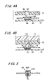
Figs. 4A and 4B are sectional views of the
condition detecting switch 39. Fig. 4A is a sectional
view of the condition detecting switch 39 assumed when
the first and second movable parts 12, 13 are in an open
condition. Fig. 4B is a sectional view of the condition
detecting switch 39 assumed when the first and second
movable parts 12, 13 are in a closed condition.
The protrusion 145 is provided between the inner
display 15 and a hinge 23 in close proximity to the hinge
23 of the first movable part 12 and protrudes toward the
second movable part 13 in a closed condition where the
first and second movable parts 12, 13 are opposed to each
other.
The hole 46 is provided in an area facing the
protrusion 145 in close proximity to the hinge 23 of the
second movable part 13 in a closed condition where the
first and second movable parts 12, 13 are opposed to each
other, and formed through the interior and the exterior
of the first movable part 12 in the hollow box shape.
The condition detecting switch 39 is provided on a
substrate 47 comprising an electric insulation material
provided inside first movable part 12. The condition
detecting switch 39 has a pattern contact section as a
discrete contact section 44 comprising a conductive
material, a common contact section 48 comprising a
conductive material such as carbon, and a support 49 for
supporting the common contact section 48. The support 49
comprises an elastic body such as rubber and supports the
discrete contact section 45 with the common contact
section 44 and the discrete contact section 45 spaced at
a predetermined distance between the hole 46 and the
discrete contact section 45.
One set of discrete contacts 44A and the other set
of discrete contacts 44B of the discrete contact section
44 are electrically connected to the controller 31 in
separate fashion by a lead formed on the substrate 47.
When the portable information processing apparatus
11 is placed in a closed condition where the first and
second movable parts 12, 13 are opposed to each other,
the protrusion 145 of the first movable part 12 is
inserted into the hole 46 of the second movable part 13.
The tip 51 of the protrusion 45 presses the common
contact section 48 supported by the support 49 of the
condition detecting switch 39 against the discrete
contact section 44 thereby electrically conducting the
one set of discrete contacts 44A and the other set of
discrete contacts 44B of the discrete contact section 44
via the common contact section 48. This causes an
electric current to flow across the discrete contacts.
The controller 31 detects a current flowing across
the discrete contacts and on detection of a current,
determines that the first and second movable parts 12, 13
are in a closed condition where the first and second
movable parts 12, 13 are opposed to each other.
In case the first and second movable parts 12, 13
are in an open condition, the protrusion 145 of the first
movable part 12 departs from the common contact section
48, which in turn departs from the discrete contact
section 44 by way of the elastic force of the support 49.
In this practice, it is impossible to cause a current to
flow across discrete contacts so that the controller 31
determines that the first and second movable parts 12, 13
are not in an open condition, that is, the first and
second movable parts 12, 13 are in a closed condition.
In this way, on the portable information processing
apparatus 11, with a simple configuration, the controller
31 can readily detect the open condition or closed
condition of the first and second movable parts 12, 13,
that is, whether the first and second movable parts 12,
13 are in an open condition or in a closed condition,
based on the state of the condition detecting switch 39.
Fig. 5 is a plan view of the discrete contact
section 44 of the condition detecting switch 39. The
discrete contact section 44 is formed so that one set of
discrete contacts 44A and the other set of discrete
contacts 44B formed in the shape of comb teeth are spaced
from each other in the direction of the face of the
substrate 47 to be engaged. The common contact section
48 comes in contact with a plurality of tongues 52 of one
or the other sets of discrete contacts 44A, 44B having a
shape of comb teeth. Even in case some of the plurality
of tongues 52 do not come into contact with the common
contact section 48, the other tongues 52 remain in
contact with the common contact section 48. This secures
electrical connection between one and the other sets of
discrete contacts 44A, 44B, thereby preventing possible
poor contact of the discrete contact section 44 and the
common contact section 48 while the press of the
protrusion 145 against the common contact section 48 is
imperfect. Thus the controller 31 can detect, with a
simple configuration, detect the closed condition and the
open condition of the first and second movable parts 12,
13 without fail.
In another embodiment of the invention, the
condition detecting switch 39 is not limited to the
aforementioned configuration but may be for example a
membrane switch. The configuration of the condition
detector including the condition detecting switch 39 is
not limited to the aforementioned configuration but may
be any configuration as long as it is possible to detect
the closed condition and the open condition of the first
and second movable parts 12, 13.
The antenna 19 transmits/receives voice data, text
data and image data by way of radio communications with a
base station over radio waves.
The radio section 40 demodulates text data, image
data and voice data received from the base station via
the antenna 19 and modulates and amplifies text data,
image data and voice data transmitted from the
communication controller 41 mentioned later and transmits
the resulting data to the base station via the antenna 19.
The communication controller 41 transmits received
data such as text data and image data demodulated by the
radio section 40 to the controller 31 based on a
predetermined communications protocol and transmits voice
data demodulated by the radio section 40 to a voice
output section 43. Data such as text data and image data
received from the distant party via the radio section 40
and the communication controller 41 is stored into the
second memory 34. The communication controller 41
transmits the send data such as text data and image data
stored into the second memory 34 and voice data input
from the voice input section 42 mentioned later to the
radio section 40.
The voice input section 42 is implemented for
example by a microphone and used to input voice data.
The voice input section 42 is provided in the inner space
of the second movable part 13 in the center of a free end
25. In a closed condition where the first and second
movable parts 12, 13 are opposed to each other, at the
free end 25 in an area of the second movable part 13
opposed to the first movable part 12 is formed a through
hole 54 which penetrates the inner space and the outer
space of the second movable part 13 where the voice input
section 42 is provided.
The voice output section 43 is implemented for
example by a loudspeaker and sounds based on the voice
data supplied from the radio communication section 41.
The voice output section 43 is provided in the inner
space of the first movable part 12 in the center of a
free end 24. In a closed condition where the first and
second movable parts 12, 13 are opposed to each other, at
the free end 24 in an area of the first movable part 12
opposed to the second movable part 13 is formed a through
hole 53 which penetrates the inner space and the outer
space of the first movable part 12 where the voice output
section 43 is provided.
Fig. 6 shows the display content of an image shot
with an imaging section 18 on an outer display 16. In
case an image shot with the imaging section 18 is
displayed on the outer display 16 and the outer display
16 is used as a camera finder, the image shot with the
imaging section 18 is displayed on the outer display 16
and a content 55 showing the setting on photographing is
displayed at the end of the display screen. In this
embodiment, the free end 24 of the first movable part 12
is assumed as top and the hinge 23 as bottom.
The content 55 showing the setting on
photographing shows for example shooting mode setting,
exposure correction setting and ZOOM/WIDE setting,
arranged in this order at the top end of the outer
display 16. Setting of shooting mode is the character N
(Normal) for a standard setting. Exposure correction
setting is for example 0 as a default and the numeric
value+N (N being a positive integer) for a setting
brighter than the default, and the numeric value-N (N
being a positive integer) for a setting darker than the
default. The exposure correction setting is adjustable
in predetermined steps. A numeric value representing the
exposure setting on the display is incremented by 1 each
time the setting becomes brighter by one step, and
decremented by 1 each time the setting becomes darker by
one step. For the ZOOM/WIDE setting, the numeric value ×N
(N being a zoom magnification) is displayed in the zoom
setting while the character W is displayed in the wide
angle setting where photographing is made using a wide
angle lens. The user references the content 55 showing
the setting on photographing to check and clearly grasp
the current setting.
The operation keys in the outer operation section
17 comprises an UP key 61 positioned in the upper portion,
a DOWN key 62 positioned in the lower portion, a LEFT key
63 positioned in the left portion, RIGHT key 64
positioned in the right portion, viewed from the side of
the outer operation section 17, and a CENTER key 65
positioned in the center of the UP key 61, DOWN key 62,
LEFT key 63 and RIGHT key 64, and the keys are arranged
in the shape of a cross. By pressing each operation key,
it is possible to enter predetermined information
corresponding to each operation key. In this embodiment,
each key in the outer operation section 17 is a push key
for entering predetermined information by pushing.
For example, by pressing the UP key 61 or DOWN key
62, exposure correction setting is modified. By pressing
the LEFT key 63 or RIGHT key 64, ZOOM/WIDE setting is
modified. For example, by holding down the CENTER key 65
for a predetermined interval of time, a function menu
screen 68 mentioned later can be displayed on the outer
display 16. For example, by holding down the CENTER key
65 for a shorter interval than the predetermined interval
of time, an image shot with the imaging section 18 can be
stored in the second memory 34, that is, the CENTER key
65 functions as a shutter key. The operation keys are
assigned so that predetermined information is entered in
response to respective operation keys.
The portable information processing apparatus 11
comprises the outer operation section 17. Even in a
closed condition where the first and second movable parts
12, 13 are opposed to each other, it is possible to
readily enter information on a predetermined display
content on the outer display 16, the image shot with the
imaging section 18 in this case, for example the
information on the setting related to photographing,
while checking the image shot with the imaging section 18.
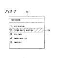
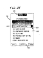
Fig. 7 shows a function menu screen 68 displayed
on the outer display 16. The function menu screen 68 is
displayed on the outer display 16 by holding down the
CENTER key 65 for a predetermined interval of time. The
function menu screen 68 displays function setting items
including: Item 1. Size Selection; Item 2. Picture
Quality Selection; Item 3. Self-timer; Item 4. Camera
Image List; and Item 5. Image Edit. The operator can
choose each item from the outer operation section 17.
When "Item 1. Size Selection" is chosen, the size
of an image to be shot with the imaging section 18 is
selected from among a plurality of sizes. When "Item 2.
Picture Quality Selection" is chosen, the number of gray
scale levels of an image shot with the imaging section 18
is modified and the image data size is modified also.
When "Item 3. Self-timer" is chosen, the data of an image
shot with the imaging section 18 is automatically stored
into the second memory 34 with a predetermined interval
of time being having elapsed. The image is stored into
the second memory 34 even if operator does not press the
CENTER key 65 as a shutter key. When "Item 4. Camera
Image List" is chosen, the image data stored into the
second memory 34 is listed. When "Item 5. Image Edit" is
chosen, the image data stored into the second memory 34
is erased.
Setting of the functions displayed on the function
menu screen 68 is made from the outer operation section
17. The functions are set to allow entry of
predetermined information in correspondence to the
operation keys, so that, in case the function menu screen
68 is displayed on the outer display 16, it is possible
to move a cursor 69 displayed on the function menu screen
68 to choose an item by pressing the UP key 61 or DOWN
key 62, and that, it is possible to validate or cancel
the item chosen with the cursor 69 by pressing the CENTER
key 65.
Even in case an image shot with the imaging
section 18 is displayed on the inner display 15, as in
the case where the image is displayed on the outer
display 16 as shown in Fig. 6, setting of functions on
photographing is displayed. In the inner operation
section 14, as is the case with the outer operation
section 17, operation keys for entering information
concerning the setting on photographing are provided.
The controller 31 switches the display to display
an image which is based on the image data temporarily
stored in the first memory 33 based on the state of the
condition detecting switch 39 during photographing with
the imaging section 18. That is, having detected that
the first and second movable parts 12, 13 are in an open
condition, the controller 31 supplies a control signal to
the first memory 33 so as to supply the image data stored
in the first memory 33 to the first display driver 35 and
displays the image which is based on the image data on
the inner display 15.
As mentioned earlier, the imaging section 18 is
provided in an exposed area to the outside in a closed
condition where the first and the second movable parts 12,
13 are opposed to each other. The operator, if wishing
to shoot a subject other than the operator with the
imaging section 18, unfolds the portable information
processing apparatus 11 to perform photographing with the
imaging section 18 oriented in a direction departing from
the operator. This allows the controller 31 to detect
that the portable information processing apparatus 11 is
in an open condition and the image shot with the imaging
section 18 to be displayed on the inner display 15. This
makes it possible to use the inner display 15 as a camera
finder.
The operator, if wishing to shoot himself/herself
with the imaging section 18, performs photographing with
the imaging section 18 facing the operator in a closed
condition where the first and second movable parts 12, 13
are opposed to each other. This allows the controller 31
to detect that the portable information processing
apparatus 11 is in a closed condition and the image shot
with the imaging section 18 to be displayed on the outer
display 16. This makes it possible to use the outer
display 16 as a camera finder.
Switchover of the camera finder display from the
inner display 15 to the outer display 16 is made by the
controller 31 when the portable information processing
apparatus 11 is placed into a closed condition where the
first and second movable parts 12, 13 are opposed to each
other from an open condition where the inner display 15
is used as a camera finder. The switchover also takes
place when the operator operates specifically assigned
operation keys in the inner operation section 14.
Switchover of the camera finder display from the
outer display 16 to the inner display 15 is made by the
controller 31 when the portable information processing
apparatus 11 is placed into an open condition from a
closed condition where the first and second movable parts
12, 13 are opposed to each other. The switchover also
takes place when the operator operates specifically
assigned operation keys in the inner operation section 14
in case the outer display 16 is used as a camera finder
in an open condition.
In this way, on the portable information
processing apparatus 11, the operator can readily select
whether the image shot with the imaging section 18 is to
be displayed on the inner display 15 or outer display 16.
Thus, the operator can promptly display an image shot
with the imaging section 18 on a display which the
operator can watch, in case the imaging section 18 is
placed into a condition where the imaging section 18 is
oriented in a direction departing from the operator for
photographing from a condition where the imaging section
18 faces the operator for photographing, or vice versa.
The controller 31 detects the state of the
condition detecting switch 39 and activates one of the
inner operation section 14 and the outer operation
section 17 and deactivates the other one of the operation
section 14 and the outer operation section 17 based on
this detection results to switch the operation section
from which predetermined information is to be entered.
The controller 31, when it is detected that the
portable information processing apparatus 11 is in a
closed condition, deactivates the inner operation section
14 and invalidates the input with each operation key in
the inner operation section 14, and activates the outer
operation section 17 and validates the input with each
operation key in the outer operation section 17. The
controller 31, when it is detected that the portable
information processing apparatus 11 is in an open
condition, activates the inner operation section 14 and
validates the input with each operation key in the inner
operation section 14, and deactivates the outer operation
section 17 and invalidates the input with each operation
key in the outer operation section 17.
The input with each operation key in the inner
operation section 14 and the outer operation section 17
is invalidated by: mechanically fixing the inner
operation section 14 and the outer operation section 17
to prevent operation by the operator; inhibiting output
of an instruction signal from the inner operation section
14 and the outer operation section 17 to the controller
31 without mechanically fixing the inner operation
section 14 and the outer operation section 17; or
inhibiting processing of the instruction signal supplied
from the inner operation section 14 and the outer
operation section 17 by the controller 31.
As mentioned earlier, in case an image shot with
the imaging section 18 is displayed on the inner display
15 and the inner display 15 is used as a camera finder,
it is detected by the controller 31 that the first and
second movable parts 12, 13 are in an open condition and
the inner operation section 14 is activated. This
validates the input with an operation key assigned to
modify the setting on photographing. Thus, the operator
can enter predetermined information with the inner
operation section 14 arranged on the same side as the
inner display 15 while watching the image shot with the
imaging section 18 displayed on the inner display 15. In
this practice, the controller 31 deactivates the outer
operation section 17 thus preventing the outer operation
section 17 from undesirably coming into contact with an
object thereby avoiding malfunction.
As mentioned earlier, in case an image shot with
the imaging section 18 is displayed on the outer display
16 and the outer display 16 is used as a camera finder,
it is detected by the controller 31 that the first and
second movable parts 12, 13 are in a closed condition and
the outer operation section 17 is activated. This
validates the input with an operation key assigned to
modify the setting on photographing. Thus, the operator
can enter predetermined information with the outer
operation section 17 arranged on the same side as the
outer display 16 while watching the image shot with the
imaging section 18 displayed on the outer display 16.
In the inner operation section 14 is provided an
operation selector key for activating one of the inner
operation section 14 and the outer operation section 17
and deactivating the other one of the inner operation
section 14 and the outer operation section 17. The
operation selector key is implemented by assigning one of
the plurality of key switches in the inner operation
section 14 to particular one. By providing an operation
selector key, it is possible to modify the setting on
whether the input from the inner operation section 14 or
input from the outer operation section 17 is validated.
This allows input of predetermined information from the
outer operation section 17 even in a condition where the
first and second movable parts 12, 13 unfold, which
enhances the operability.
In another embodiment of the invention, the
operation selector key may be provided in the outer
operation section 17, or in each of the inner operation
section 14 and the outer operation section 17.
The protrusion 145, hole 46 and condition
detecting switch 39 are provided in close proximity to
the hinge 23. Thus, the state of the condition detecting
switch 39 changes even by a slight angle displacement
about the hinge 23 from a closed condition of the first
and second movable parts 12, 13. In the use condition
where the first and second movable parts 12, 13 unfold by
90 degrees or more and 180 degrees or less about the
hinge from a closed condition, setting in the operation
section to activate the inner operation section 14 and
deactivate the outer operation section 17 is complete.
In case the first and second movable parts 12, 13 are
placed in a closed condition from an open condition,
response of switchover of the operation section is quick.
In case the first and second movable parts 12, 13 are
placed into an open condition from a closed condition,
the operation section is not switched promptly thus
preventing malfunction.
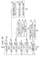
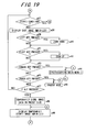
Fig. 8 is a flowchart showing the processing
operation of a controller 31 assumed when photographing
is made with an imaging section 18. Execution proceeds
from step S1 to step S2 where it is determined whether a
first and a second movable parts 12, 13 are in an open
condition based on the state of the condition detecting
switch 39. In case it is determined that the first and
second movable parts 12, 13 are in an open condition in
step S2, execution proceeds to step S3. When it is
determined that the first and second movable parts 12, 13
are not in open condition in step S2, execution proceeds
to step S11.
In step S3, an inner operation section 14 is
activated and an outer operation section 17 is
deactivated. This validates only the input from the
inner operation section 14.
In step S4, a camera shooting mode is started.
That is, a control signal is supplied to an image
processor 32 to cause a first memory 33 to store image
data. Execution then proceeds to step S5.
In step S5, a control signal is supplied to the
first memory 33 to cause image data stored in the first
memory 33 to be supplied to a first display driver 38.
Then the image shot with the imaging section 18 is
displayed on the inner display 15. Execution then
proceeds to step S6. This allows the inner display 15 to
be used as a camera finder.
In step S6, it is determined whether a shutter
button for inputting an instruction to store image data
of an image generated with the imaging section 18 into a
second memory 34 has been operated. In case it is
determined that the shutter button has been operated in
step S6, execution proceeds to step S7. In case it is
determined that the shutter button has not been operated
in step S6, execution proceeds to step S10.
In step S7, a control signal is supplied to the
second memory 34 to cause image data of an image shot
with the imaging section 18 to be stored into the second
memory 34, and execution proceeds to step S8. In step S8,
it is determined whether an instruction to quit the
shooting mode has been issued, that is, an instruction to
stop photographing with the imaging section 18 has been
input from the inner operation section 14. In case it is
determined that an instruction to quit the shooting mode
has been issued in step S8, execution proceeds to step S9
where processing is terminated. In case it is determined
that an instruction to quit the shooting mode has not
been issued in step S8, execution proceeds to step S4.
The instruction to quit the shooting mode is issued for
example when the operator operates the shooting
termination key assigned to any one of the operation keys
in the inner operation section 14.
In step S10, it is determined whether the display
for displaying an image shot with the imaging section 18
on the outer display 16 has been switched over.
Switchover of the display from the inner display 15 to
the outer display 16 is determined based on whether the
state of the condition detecting switch 39 has changed or
whether a display selector key provided in the inner
display 15 has been operated. In case it is determined
that the display has been switched over in step S10,
execution proceeds to step S11. In case it is determined
that the display has not been switched over in step S10,
execution proceeds to step S5.
In step S11, the outer operation section 17 is
activated and the inner operation section 14 is
deactivated. This validates only the input from the
outer operation section 17.
In step S12, the camera shooting mode is started,
that is, a control signal is supplied to the image
processor 32 to cause the first memory 33 to store image
data, and photographing is performed by the imaging
section 18. Execution then proceeds to step S13. In
step S13, a control signal is supplied to the first
memory 33 to cause image data stored in the first memory
33 to be supplied to a second display driver 36. Then
the image which is based on the image data generated by
the imaging section 18 is displayed on the outer display
16. Execution then proceeds to step S14. This allows
the outer display 16 to be used as a camera finder.
In step S14, a control signal is supplied to the
second memory 34 and it is determined whether a shutter
button for inputting an instruction to store image data
of an image shot with the imaging section 18 into the
second memory 34 has been operated. In case it is
determined that the shutter button has been operated in
step S14, execution proceeds to step S15. In case it is
determined that the shutter button has not been operated
in step S14, execution proceeds to step S17.
In step S15, the data of an image shot with the
imaging section 18 is stored into the second memory 34
and execution proceeds to step S16. In step S16, it is
determined whether an instruction to quit the shooting
mode has been issued, that is, an instruction to stop
photographing with the imaging section 18 has been input
from the outer operation section 17. In case it is
determined that an instruction to quit the shooting mode
has been issued in step S16, execution proceeds to step
S9 where processing is terminated. In case it is
determined that an instruction to quit the shooting mode
has not been issued in step S16, execution proceeds to
step S12. The instruction to quit the shooting mode with
the imaging section 18 is issued for example when the
operator continuously presses the CENTER key 65 in the
outer operation section 17.
In step S17, it is determined whether the display
for displaying an image shot with the imaging section 18
on the inner display 15 has been switched over.
Switchover of the display from the outer display 16 to
the inner display 15 is determined based on whether the
state of the condition detecting switch 39 has changed or
whether the display selector key provided in the inner
display 15 has been operated. In case it is determined
that the display has been switched over in step S17,
execution proceeds to step S3. In case it is determined
that the display has not been switched over in step S17,
execution proceeds to step S13.
The inner operation section 14 is covered by the
first movable part 12 when the first and second movable
parts 12, 13 are in a closed condition so that the
operator cannot operate the inner operation section 14.
In another embodiment of the invention, the inner
operation section 14 may remain activated in step S3
mentioned earlier.
In another embodiment of the invention, the outer
operation section 17 may not be deactivated but may be
activated in case the first and second movable parts 12,
13 are in an open condition. In this case, it is
possible to enter predetermined information from any one
of the inner operation section 14 and the outer operation
section 17.
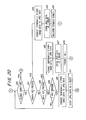
Fig. 9 is a perspective view of portable
information processing apparatus 71 according to another
embodiment of the invention. The portable information
processing apparatus 71 comprises a first movable part
and a second movable part 12, 13 connected movably in
relative angular displacement from a closed condition
where the movable parts are opposed to each other to an
open condition where the areas opposed in the closed
condition are exposed to the outside, an inner operation
section for entering predetermined information, an inner
display for displaying a predetermined display content in
response to predetermined information entered from the
inner operation section, an outer display 16 for
displaying a predetermined display content, an outer
operation section 72 for entering predetermined
information on the predetermined display content
displayed on the outer display, an imaging section 18,
and an antenna 19. The portable information processing
apparatus 71 according to this embodiment has the same
configuration as that of the aforementioned embodiment
except that the outer operation section 72 is used
instead of the outer operation section 17. The same
components of the portable information processing
apparatus 71 shown in Fig. 9 as those of the portable
information processing apparatus 11 are given the same
numerals and signs and the corresponding description is
omitted. In this embodiment, the free end 24 of the
first movable part 12 is assumed as a top and the hinge
23 as a bottom.
The outer operation section 72 is provided on the
side of the first movable part 12. The outer operation
section 72 has the same configuration as the outer
operation section 17 of the portable information
processing apparatus 11 according to the aforementioned
embodiment and comprises a plurality of operation keys
including an UP key 61, a DOWN key 62 and a CENTER key 65.
For example, by pressing the UP key 61 or DOWN key 62, it
is possible to modify exposure correction setting and
ZOOM/WIDE setting.
The outer operation section 72 is arranged on the
right-hand side as viewed from the outer display 16.
When the operator orients the imaging section 18 toward
himself/herself while holding the portable information
processing apparatus 71 in his/her right hand, the
operator can operate the outer operation section 17 with
his/her thumb while holding the entire apparatus. This
enhances the operability and prevents the portable
information processing apparatus 71 from dropping
undesirably.
Fig. 10 is a perspective view of portable
information processing apparatus 81 according to another
embodiment of the invention. The portable information
processing apparatus 81 comprises a first movable part 12
and a second movable part 13 connected movably in
relative angular displacement from a closed condition
where the movable parts are opposed to each other to an
open condition where the areas opposed in the closed
condition are exposed to the outside, an inner operation
section for entering predetermined information, an inner
display for displaying a predetermined display content in
response to predetermined information entered from the
inner operation section, an outer display 16 for
displaying a predetermined display content, an outer
operation section 82 for entering predetermined
information on the predetermined display content
displayed on the outer display, an imaging section 18,
and an antenna 19. The portable information processing
apparatus 81 according to this embodiment has the same
configuration as that of the aforementioned embodiment
except that the outer operation section 72 is used
instead of the outer operation section 17. The same
components of the portable information processing
apparatus 81 shown in Fig. 10 as those of the portable
information processing apparatus 11 are given the same
numerals and signs and the corresponding description is
omitted. In this embodiment, the free end 24 of the
first movable part 12 is assumed as a top and the hinge
23 as a bottom.
The outer operation section 82 is provided on the
side of the second movable part 13. The outer operation
section 72 has the same configuration as the outer
operation section 17 of the portable information
processing apparatus 11 according to the aforementioned
embodiment and comprises a plurality of operation keys
including an UP key 61, a DOWN key 62 and a CENTER key 65.
For example, by pressing the UP key 61 or DOWN key 62, it
is possible to modify exposure correction setting and
ZOOM/WIDE setting.
The outer operation section 82 is arranged to the
right-hand side of the second movable part 12 as viewed
from the outer display 16 in a closed condition where the
first and second movable parts 12, 13 fold closed while
opposed to each other. When the operator orients the
imaging section 18 toward himself/herself while holding
the portable information processing apparatus 81 in
his/her right hand, the operator can operate the outer
operation section 17 with his/her thumb while holding the
entire apparatus. This enhances the operability and
prevents the portable information processing apparatus 81
from dropping undesirably.
While the inner display 15 and the outer display
16 are provided on the first movable part in the
aforementioned embodiments, the inner display 15 may be
provided in an area where the first and second movable
parts 12, 13 are opposed to each other in a closed
condition where the first and second movable parts 12, 13
fold closed. The outer display 16 may be provided in an
area exposed to the outside in a closed condition where
the first and second movable parts 12, 13 fold closed.
While the imaging section 18 is arranged closer to
the free end 24 than the outer display 16 provided on the
free end 24 of the movable part 12 in the aforementioned
embodiments, the imaging section 18 may be arranged
closer to the hinge 23 than the outer display 16. While
the antenna 19 is arranged on the first movable part 12
in the aforementioned embodiments, the antenna 19 may be
provided on the second movable part 13.
Fig. 11 shows a relationship between the outer
display 16 and the keys on the back of the outer
operation section 17 of portable information processing
apparatus 100 according to another embodiment of the
invention. Fig. 12 shows a surface including the imaging
section 18 of the portable information processing
apparatus 100 in a closed condition. Fig. 13 is a
drawing of the portable information processing apparatus
100 in an open condition seen from one side in the
direction of thickness. Fig. 14 is a side view of the
portable information processing apparatus 100 in a closed
condition. Fig. 15 is another side view of the portable
information processing apparatus 100 in a closed
condition. The portable information processing apparatus
100 according to this embodiment has the same
configuration as that of the portable information
processing apparatus 11 according to the aforementioned
embodiment except that they are different partially. The
same components are given the same numerals and signs and
the corresponding description is omitted.
This embodiment shows an example.of the portable
information processing apparatus 100 applied to a folding
cellular telephone with a small camera mounted. The
portable information processing apparatus 100 may be also
applied a variety of cellular telephones including a
sliding-type cellular telephone where the first movable
part 12 is displaced slidably relative to and
approximately in parallel with the second movable part 13,
a rotation-type cellular telephone where the first
movable part 12 is rotated in displacement about an axis
parallel with the direction of thickness of the first
movable part 12 with respect to the second movable part
13, and a cellular telephone having a selected
combination of the structure of a folding, sliding-type
and rotation type.
On the first movable part 12, the outer operation
section 17 is provided on each of the back of the inner
display 15 (see Fig. 11) and one side of the first
movable part 12 (see Fig. 14). In other words, the outer
operation section 17 is provided in an area exposed to
the outside on the first movable part 12 in a closed
condition where the first and second movable parts 12, 13
fold closed. The outer operation section 17 comprises a
key operation section 109 provided on the back and a
shutter key 110 (see Fig. 14) provided on the side.
The key operation section 109 comprises three back
keys 109a, 109b, 109c which are arranged with an
appropriate interval among them. Each back key 109a,
109b, 109c shown in Fig. 11 corresponds to an operation
piece. One back key 109a among the back keys 109a, 109b,
109c is arranged close to the free end of the first
movable part 12, in close proximity to the midpoint of
one side 112 of a rectangular display area in the outer
display 16. The back key 109a is defined as a CENTER key
109a. Another back key 109b is arranged in close
proximity to one of the four corners of the rectangular
display area, that is, the intersection of the side 112
and one side 113 adjacent thereto. The back key 109b is
defined as a LEFT key 109b. The remaining back key 109c
is arranged in close proximity to one of the four corners
of the rectangular display area, that is, the
intersection of the side 112 and one side 114 adjacent
thereto. The back key 109c is defined as a RIGHT key
109c. As mentioned later, by selectively operating the
CENTER key 109a, LEFT key 109b, RIGHT key 109c, and
shutter key 110, it is possible to zoom up/down a shot
image, temporarily store image data or store image data,
register a standby display screen, and transmit
electronic mails. The CENTER key 109a is provided
slightly closer to the free end 25 of the first movable
part 12 than the LEFT key 109b and the RIGHT key 109c.
When the CENTER key 109a is operated, this prevents the
fingers of the operator from undesirably coming in
contact with the LEFT key 109b and the RIGHT key 109c.
The back keys 109a, 109b, 109c correspond to function
setting operation buttons.
On the second movable part 13, an imaging section
18 and an antenna 19 are provided at the back of the
inner operation section 14. The imaging section 18 is
provided, while externally oriented, in an area exposed
to the outside in a closed condition where the first and
second movable parts 12, 13 fold closed, that is, in an
area other than the areas where the first and second
movable parts 12, 13 are opposed in a closed condition.
The imaging section 18 is provided close to the hinge 23
of the second movable part 13, facing the side opposite
to the display face of the outer display 16 in a closed
condition. That is, the imaging lens 18 of the imaging
section 18 is provided facing the side opposite to the
inner operation section 14.
A shutter key 110 is provided on one side of the
second movable part 13 in this embodiment. The shutter
key 110 may be provided on one side of the first movable
part 12 in another embodiment of the invention. By
providing the shutter key 110 on one side of the portable
information processing apparatus 100, it is possible to
take a picture while holding the portable information
processing apparatus 100 in a closed condition, one side
facing upward and the other side facing downward. This
enhances the operability.
In close proximity to the imaging section 18 is
provided a light-emitting section 201. The light-emitting
section 201 facing the side opposite to the
display face of the outer display 16 emits a light in the
closed condition to illuminate the area shot with the
imaging section 18. In the other side of the second
movable part 13 is formed a detachable memory slot 202
for attaching a detachable memory.
Operation keys 14a in the inner operation section
14 includes for example at least a LEFT key 129, a RIGHT
key 130, an F key 131, a mail key 133, a camera key 134,
a power key 135 and a clear key 136. The LEFT key 129,
the RIGHT key 130, the F key 131, the mail key 133, the
camera key 134, the power key 135 and the clear key 136
are provided close to the hinge 23 of the second movable
part 13. On the left of the F key 131 is provided the
LEFT key 129. On the right of the F key 131 is provided
the RIGHT key 130.
Fig. 16 is a block diagram showing the electrical
configuration of the portable information processing
apparatus 100. The portable information. processing
apparatus 100 comprises a light-emitting section 201 and
a detachable memory connector 203 as well as the
aforementioned first and second movable parts 12, 13, the
inner operation section 14, the inner display 15, the
outer display 16, the outer operation section 17, the
imaging section 18, the antenna 19, a controller 31, the
image processor 32, the first memory 33, the second
memory 34, the first display driver 35, the second
display driver 36, the first backlight unit 37, the
second backlight unit 38, the condition detecting switch
39, the radio section 40, the communication controller 41,
the voice input section 42 and the voice output section
43.
The light-emitting section 201 emits a light based
on a control signal supplied by the controller 31. The
light-emitting section 201 is a light which helps
photographing when the surrounding is dark. Thereafter,
there is a case where the light-emitting section 201 is
called a picture light. The light-emitting section 201
is implemented for example by a Light Emitting Diode
(LED).
The detachable memory connector 203 is an
interface for attaching a detachable memory in a
detachable fashion. The detachable memory is implemented
for example by a nonvolatile recording medium such as a
semiconductor memory. The semiconductor memory is for
example a flash memory. The detachable memory connector
203 is electrically connected to the controller 31. The
controller 31 stores predetermined information including
for example image data obtained through the imaging
section 18 into a detachable memory attached to the
detachable memory connector 203. Or, the controller 31
reads predetermined information from the detachable
memory 18. The detachable memory inserted into the
detachable memory slot 202 is attached to the detachable
memory connector 203 in a detachable fashion in relation
to each other.
By storing the image shot into a detachable memory
connected to the detachable memory connector 203, it is
readily possible to increment the image data items to be
stored and transfer image data to another unit via a
detachable memory, which enhances the convenience.
The controller 31 has a setting information
storage section 204 implemented for example by a
nonvolatile storage medium such as a flash memory. Into
the setting information storage section 204 is stored
information on the setting of portable information
processing apparatus such as information on the
magnification of photographing, a standby screen, and a
location for storing shot images.
Fig. 17 through Fig. 22 are flowcharts showing the
operation on photographing of the portable information
processing apparatus 100. The outer display 16 is
represented as a sub-LCD in Fig. 17 and Fig. 21 and the
inner display 15 is represented as a main LCD in Fig. 19
and Fog. 22. Operation shown in the flowchart of Figs.
17 through Fig. 22 is executed based on a program
previously stored in the processor 31. The program is
executed by a central processing unit (CPU).
When the operator operates the shutter key 110 for
a predetermined interval of time, to be specific, presses
the shutter key 110 for two seconds in a standby mode
awaiting a call or an electronic mail, execution proceeds
from step a0 to step a1 in the flowchart of Fig. 17.
In step a1, the controller 31 places the portable
information processing apparatus 100 into a camera mode
or shooting mode. The controller 31 starts the imaging
section 18 and supplies a control signal to an image
processor 32 and a first memory 32 to start photographing
with the imaging section 18. When the processing in step
a1 is complete, execution proceeds to step a2.
In step a2, the controller 31 determines whether
the portable information processing apparatus is in a
closed condition based on the state of a condition
detecting switch 39. In case it is determined that the
portable information processing apparatus is in a closed
condition, execution proceeds to step a3. The controller
31 displays an image obtained through the imaging section
18 on the outer display 16. Hereinafter, an image
obtained through the imaging section 18 is also refereed
to as a shot image.
Fig. 23 shows a display screen 150 of the outer
display 16 in a camera mode. Fig. 23 shows the display
screen 150 in the initial setting or default state.
Below the display screen 150 shown in Fig. 23 are
provided the back keys 109a, 109b, 109c. In an end area
of the display screen 150 close to the hinge 23 is
provided a condition display area 151 for displaying the
condition of the portable information processing
apparatus 100. In the condition display area 151 is
shown the condition of the portable information
processing apparatus 100 by way of predetermined images
and symbols. An image or a symbol to represent the
condition of the portable information processing
apparatus 100 is also referred to as a pictogram. The
pictogram represents for example magnification of
photographing or a location where a shot image is stored.
In the bottom area of the display screen 150, that
is, in the end area close to the back keys 109 is
displayed an operation key description area 152 including
the description on the LEFT key 109b, the RIGHT key 109c
and the CENTER key 109a which belong to the back keys 109.
In the operation key description area 152 are displayed
the characters "Zoom Down", "Zoom Up", and "Menu". The
"Zoom Down" is displayed in close proximity to the LEFT
key 109b. "Zoom Up" is displayed in close proximity to
the RIGHT key 109c. "Menu" is displayed in close
proximity to the CENTER key 109a. In this way,
corresponding characters are displayed in the display
area of the outer display 16 in close proximity to each
key. Thus the operator can operate a desired key while
checking the characters displayed. In this embodiment, a
shot image display area 153 is provided in an area
between the condition display area 151 and the operation
key description area 152. The controller 31 displays a
shot image shot with the imaging section 18 in the shot
image display area 153. The shot image displayed in the
shot image display area 153 is updated at predetermined
intervals based on the image data supplied from the
imaging section 18.
In the shot image display area 153, a
photographing magnification display bar 154 to show the
current magnification of photographing is displayed close
to the operation key description area 152. The
photographing magnification display bar 154 extends in
parallel with one side 112 of the rectangular display
area, that is, in parallel with the lateral direction in
Fig. 23. For example, one end 155 of the photographing
magnification display bar 154 is associated with the
minimum magnification of photographing and the other end
156 with the maximum magnification of photographing.
Then, the area from one end or the other end to the
section is displayed for example in a color different
from that of the other areas as shown in Fig. 23. This
allows the operator to immediately understand the current
magnification of photographing.
In step a3, the controller 31 sets the LEFT key
109b and the RIGHT key 109c to the command input function
to input a command to modify the magnification of
photographing as a function on photographing, while
displaying the image shot with the imaging section 18 on
the outer display 16.
Execution then proceeds to step a4. The
controller 31 determines whether the operator has
operated the LEFT key 109b used by the operator to enter
a Zoom Down command. In case it is determined that the
LEFT key 109b has been operated, execution proceeds to
step a5. In case it is determined that the LEFT key 109b
has not been operated, execution proceeds to step a6.
In step a5, the controller 31 displays in zoom
down fashion part of the shot image shot with the imaging
section 18 on the outer display 16. That is, the
controller 31 decreases the magnification of
photographing. On the portable information processing
apparatus 100, the operator can zoom down a shot image in
steps each time he/she operates the LEFT key 109b. The
operator can hold down the LEFT key 109b to continuously
zoom down the shot image. When the operator holds down
the LEFT key 109b for a predetermined interval of time
(for example about two seconds), the controller 31
determines that the LEFT key 109b has been held down.
The predetermined interval of time is not limited to two
seconds.
When the processing in step a5 is complete,
execution proceeds to step a6. In step a6, the
controller 31 determines whether the operator has
operated the RIGHT key 109c corresponding to Zoom Up
function. In case it is determined that the RIGHT key
109c has been operated, execution proceeds to step a7.
In case it is determined that the RIGHT key 109c has not
been operated, execution proceeds to step a8.
In step a7, the controller 31 displays in zoom up
fashion part of the shot image shot with the imaging
section 18 on the outer display 16. That is, the
controller 31 increases the magnification of
photographing. On the portable information processing
apparatus 100, the operator can zoom up a shot image in
steps each time he/she operates the RIGHT key 109c. The
operator can hold down the RIGHT key 109c to continuously
zoom up the shot image. When the operator holds down the
RIGHT key 109c for a predetermined interval of time (for
example about two seconds), the controller 31 determines
that the RIGHT key 109c has been held down. The
predetermined interval of time is not limited to two
seconds.
When the processing in step a7 is complete,
execution proceeds to step a8. In step a8, the
controller 31 determines whether the operator has
operated the CENTER key 109a used by the operator to
display a menu on the outer display 16. In case it is
determined that the CENTER key 109a has been operated,
execution proceeds to step a9. In step a9, the
controller 31 determines whether the CENTER key 109a has
been released. In other words, the controller 31
determines whether the operator has canceled the
operation of the CENTER key 109a. In case it is
determined that the CENTER key 109a has been released,
execution proceeds to step a10 (a subroutine in Fig. 21).
When the processing in step a10 is complete, execution
proceeds to step a1.
In case the processor 31 determines that the
CENTER key 109a has not been released in step a9,
execution proceeds to step a11. The controller 31
determines whether a predetermined interval of time (for
example about five seconds) has elapsed in step a11. The
predetermined interval of time is not limited to five
seconds. In case it is determined that the predetermined
interval of time has not elapsed, execution proceeds to
step a9. In case it is determined that the predetermined
interval of time has elapsed, execution proceeds to step
a12, where the portable information processing apparatus
100 is placed into the standby mode awaiting a call or an
electronic mail.
In case the controller 31 determines that the
RIGHT key 109a has not been operated in step a8,
execution proceeds to step a13. In step a13, the
controller 31 determines whether the operator has
operated the shutter key 110. In case it is determined
that that the shutter key 110 has not been operated,
execution proceeds to step a2. In case it is determined
that that the shutter key 110 has been operated,
execution proceeds to step a14.
In step a14, the controller 31 determines whether
the operator has pressed the shutter 110 halfway. The
"halfway" refers to a condition where the shutter key 110
is pressed half the amount of the full travel of the
operation piece, or the shutter key 110 is pressed once.
In this embodiment, the condition where the shutter key
110 is pressed half the amount of the full travel of the
operation piece is defined as pressing halfway.
In step a14, in case the controller 31 determines
that the shutter key 110 has been pressed halfway,
execution proceeds to step a15 In step a15 the
controller 31 displays a focus-locked image on the outer
display 16.
Fig. 24 shows the display screen 150 of the outer
display 16 assumed after the focus is locked. With a
focus lock, an image shot with the imaging section 18 is
displayed on the outer display 16. In the operation key
description area 152 of the display screen 150 are
displayed the characters "Zoom Down" and "Zoom Up". The
"Zoom Down" is displayed in close proximity to the LEFT
key 109b. "Zoom Up" is displayed in close proximity to
the RIGHT key 109c. The image displayed in the shot
image display area 153 is a image displayed on the outer
display 16 when the shutter key 110 is pressed. From now
on, image data supplied from the imaging section 18 will
not be displayed on the outer display 16.
Execution then proceeds to step a16. The
controller 31 determines whether the operator has
operated the LEFT key 109b used by the operator to enter
a Zoom Down command. In case it is determined that the
LEFT key 109b has been operated, execution proceeds to
step a17 In case it is determined that the LEFT key
109b has not been operated, execution proceeds to step
a18.
In step a17, the controller 31 displays on the
outer display 16 in zoom down fashion part of the shot
image displayed on the outer display 16. That is, the
controller 31 decreases the magnification of
photographing. On the portable information processing
apparatus 100, the operator can zoom down a shot image in
steps each time he/she operates the LEFT key 109b. The
operator can hold down the LEFT key 109b to continuously
zoom down the shot image. When the operator holds down
the LEFT key 109b for a predetermined interval of time
(for example about two seconds), the controller 31
determines that the LEFT key 109b has been held down.
The predetermined interval of time is not limited to two
seconds.
When the processing in step a17 is complete,
execution proceeds to step a18. In step a18, the
controller 31 determines whether the operator has
operated the RIGHT key 109c used by the operator to enter
a Zoom Up command. In case it is determined that the
RIGHT key 109c has been operated, execution proceeds to
step a19. In case it is determined that the RIGHT key
109c has not been operated, execution proceeds to step
a20.
In step a19, the controller 31 displays on the
outer display 16 in zoom up fashion part of the shot
image displayed on the outer display 16. That is, the
controller 31 increases the magnification of
photographing. On the portable information processing
apparatus 100, the operator can zoom up a shot image in
steps each time he/she operates the RIGHT key 109c. The
operator can hold down the RIGHT key 109c to continuously
zoom up the shot image. When the operator holds down the
RIGHT key 109c for a predetermined interval of time (for
example about two seconds), the controller 31 determines
that the RIGHT key 109c has been held down. The
predetermined interval of time is not limited to two
seconds.
When the processing in step a19 is complete,
execution proceeds to step a20. In step a20, the
controller 31 determines whether the operator has pressed
the shutter 110 all the way in. The "all the way in"
refers to a condition where the shutter key 110 is
pressed all the amount of the full travel of the
operation piece, or the shutter key 110.is pressed twice.
In this embodiment, the condition where the shutter key
110 is pressed all the amount of the full travel of the
operation piece is defined as pressing all the way in.
In step a20, in case the controller 31 determines
that the shutter key 110 has been pressed all the way in,
execution proceeds to step a21. In step a20, in case the
controller 31 determines that the shutter key 110 has not
been pressed all the way in, execution proceeds to step
a16. In step a14, in case the controller 31 determines
that the shutter key 110 has not been pressed halfway,
execution proceeds to step a21.
In step a21, the controller 31 temporarily stores
image data obtained through the imaging section 18 in a
preset size into the first memory 33. Information on the
size of the image data is previously stored in the
setting information storage section 204 of the controller
31.
In this way, it is possible to readily modify the
magnification of photographing by simply operating the
LEFT key 109b or RIGHT key 109c so that the operability
of photographing is enhanced. The magnification of
photographing can be modified after focus lock. Thus,
the magnification of photographing of an image shot under
a preset magnification can be readily modified thereby
enhancing the freedom of photographing.
When the processing in step a21 is complete,
execution proceeds to step a22. In step a22, the
controller 31 displays the shot image temporarily stored
in step a21 on the outer display 16.
Fig. 25 shows the display screen 150 of the outer
display 16 assumed after a temporarily stored shot image
is displayed. By way of the processing in step a21, the
image which is based on the temporarily stored image data
is displayed on the display screen 150 of the outer
display 16. In the operation key description area 152
are displayed the characters "Send Mail", "Store", and
"Screen Setting". The "Send Mail" is displayed in close
proximity to the LEFT key 109b. "Store" is displayed in
close proximity to the CENTER key 109a. "Screen Setting"
is displayed in close proximity to the RIGHT key 109c.
When the processing in step a22 is complete,
execution proceeds to step a23 shown in Fig. 18. In step
a23, the controller 31 determines whether the portable
information processing apparatus 100 is in a closed
condition based on the state of the condition detecting
switch 39. In case it is determined that the portable
information processing apparatus is not in a closed
condition, execution proceeds to step a49 shown in Fig.
19. In step a23, in case it is determined that the
portable information processing apparatus 100 is in a
closed condition, execution proceeds to step a24. In
step a24, the controller 31 determines whether the RIGHT
key 109c has been operated. In step a24, the RIGHT key
109c serves as a standby display screen registration key.
In step a24, in case it is determined that that
RIGHT key 109c has been operated, execution proceeds to
step a25. The controller 31 compresses the image data
temporarily stored in the step a21 by way of a
predetermined compression method. In this embodiment,
JPEG (Japanese Photographic Experts Group) is used as the
compression method to convert the temporarily stored
image data to JPEG data. The step of converting to JPEG
data is the same as the step of fixing the compression
ratio based on the image data size obtained through the
imaging section 18 and the send data size which can be
transmitted by the communication section 40 and using the
compression ratio to convert the temporarily stored image
data to JPEG data.
Next, execution proceeds to step a26. The
controller 31 stores as a library the JPEG data obtained
by the processing in step a25 for example into the second
memory 34 or detachable memory based on the setting
information stored in the setting information storage
section 204. Execution then proceeds to step a27, where
a standby display screen on the inner display 15, that is,
a standby image is registered, then execution proceeds to
step a12 in Fig. 17. In a closed condition and in a
standby mode, the controller 31 displays the image
registered as a shot standby image on the outer display
16. The controller 31 has a setting information storage
section 204 implemented for example by a nonvolatile
memory such as a flash memory and stores the information
on the image registered as a standby image into the
setting information storage section 204.
In case the controller 31 determines that the
RIGHT key 109c has not been operated in step a24,
execution proceeds to step a28. In step a28, the
controller 31 determines whether the operator has
operated the LEFT key 109b. In step a28, the LEFT key
109b corresponds to a JPEG data storage key and a main
send key. In case it is determined that the LEFT key
109b has been operated, execution proceeds to step a29.
The controller 31 converts the image data temporarily
stored in step a21 to for example JPEG data. Execution
then proceeds to step a23. The controller 31 stores as a
library the JPEG data obtained by the processing in step
a23 for example into the second memory 34 or detachable
memory based on the setting information stored in the
setting information storage section 204. Execution then
proceeds to step a31, where the image data stored in the
second memory 34 in step a23 is attached to an electronic
mail and transmitted to a predetermined destination.
Execution then proceeds to step a12 in the flowchart of
Fig. 17. The predetermined destination is stored in the
setting information storage section 204. The operator
can use the inner operation section 14 to register the
predetermined destination to the setting information
storage section 204. In this way, with simple operation
of the RIGHT key 109c, it is possible to transmit a shot
image to a predetermined destination, thereby enhancing
the scope of use of the shot image.
In case the controller 31 determines that the
RIGHT key 109a has not been operated in step a28,
execution proceeds to step a32. In step a32, the
controller 31 determines whether the operator has
operated the CENTER key 109a. In step a32, the CENTER
key 109a corresponds to a JPEG data storage key and a
return to photographing key. In case it is determined
that the CENTER key 109a has not been operated, execution
proceeds to step a23. In case it is determined that the
CENTER key 109a has been operated in step a32, execution
proceeds to step a33. In step a33, the controller 31
determines whether the CENTER key 109a has been released.
In case the controller 31 determines that the operator
has released the CENTER key 109a, execution proceeds to
step a34.
In step a34, the image data temporarily stored in
step a21 is converted to for example JPEG data.
Execution then proceeds to step a35. The controller 31
stores as a library the JPEG data obtained in step a34
for example into the second memory 34 or detachable
memory based on the setting information stored in the
setting information storage section 204. When the
processing of step a35 is complete, execution proceeds to
step a1 in the flowchart of Fig. 17.
In case the processor 31 determines that the
CENTER key 109a has not been released in step a33,
execution proceeds to step a36. The controller 31
determines whether a predetermined interval of time has
elapsed in step a36. The predetermined interval of time
is for example about five seconds although it is not
limited to five seconds. In case it is determined that
the predetermined interval of time has not elapsed,
execution returns to step a33. In step a36, in case it
is determined that the predetermined interval of time has
elapsed, execution proceeds to step a12 in the flowchart
of Fig. 17.
In case it is determined that the portable
information processing apparatus 100 is not in a closed
condition in step a2 in the flowchart of Fig. 17,
execution proceeds to step a37 in the flowchart of Fig.
19. Here, the controller 31 determines whether the
portable information processing apparatus 100 is in a
closed condition again. In case it is determined that
the portable information processing apparatus 100 is in a
closed condition in step a37, execution proceeds to step
a2 in the flowchart of Fig. 17. In case the controller
31 determines that the portable information processing
apparatus 100 is not in a closed condition, that is, the
portable information processing apparatus 100 is in an
open condition, execution proceeds to step a38.
In the step a38, the controller 31 displays a shot
image on the inner display 15. Execution then proceeds
to step a39. The controller 31 determines whether the
operator has operated a LEFT key 129 included in the
operation key 14a used by the operator to enter a Zoom
Down command. In case it is determined that the LEFT key
129 has been operated, execution proceeds to step a40.
The controller 31 displays in zoom down fashion a shot
image, or a reduced shot image on the inner display 15.
Execution then proceeds to step a41. The
controller 31 determines whether the operator has
operated the RIGHT key 130 used by the operator to enter
a Zoom UP command. In case it is determined that the
RIGHT key 130 has been operated, execution proceeds to
step a42. The controller 31 displays in zoom up fashion
a shot image on the inner display 15. Execution then
proceeds to step a43. The controller 31 determines
whether the operator has operated a camera key 134 (see
Fig. 13) included in the operation key 14a. In case it
is determined by the controller 31 that the camera key
134 has been operated, execution proceeds to step a44 (a
subroutine in Fig. 22).
In case the controller 31 determines that the
camera key 134 has not been operated in step a43,
execution proceeds to step a45. In step a45, the
controller 31 determines whether the operator has
operated a power key 135 included in the operation key
14a. In case the controller 31 determines that the power
key 135 has been operated, execution proceeds to step a46.
In step a46, the portable information processing
apparatus 100 is placed in a standby mode awaiting a call
or an electronic mail.
In case the controller 31 determines that the
power 135 has not been operated in step a45, execution
proceeds to step a47. In step a47, the controller 31
determines whether the operator has operated an F key 131
included in the operation key 14a. In case the
controller 31 determines that the F key 131 has not been
operated, execution proceeds to step a37. In case the
controller 31 determines that the F key 131 has been
operated, execution proceeds to step a48.
In step a48, the controller 31 temporarily stores
image data generated in a preset size into the first
memory 33. Execution then proceeds to step a49. The
controller 31 displays the temporarily stored shot image
on the inner display 15.
Execution then proceeds to step a50 shown in Fig.
20. The controller 31 determines whether the portable
information processing apparatus 100 is in a closed
condition based on the state of a condition detecting
switch 39. In case it is determined that the portable
information processing apparatus 100 is in a closed
condition, execution proceeds to step a22 in the
flowchart of Fig. 17. In case it is determined that the
portable information processing apparatus 100 is not in a
closed condition, execution proceeds to step a51. In
step a51, the controller 31 determines whether the
operator has operated a camera key 134.
In case it is determined that the camera key 134
has been operated, execution proceeds to step s52. The
controller 31 converts the image data temporarily stored
in step a48 to for example JPEG data. Execution then
proceeds to step a53. The controller 31 stores as a
library the JPEG data obtained in step a52 for example
into the second memory 34 or detachable memory based on
the setting information stored in the setting information
storage section 204. Execution then proceeds to step a54.
The standby display screen on the outer display 16, that
is, a standby image is registered, then execution
proceeds to step a46 in the flowchart of Fig. 19. In an
open condition and in a standby mode, the controller 31
displays the image registered as a shot standby image on
the inner display 15. The information on the image
registered as a standby image is stored into the setting
information storage section 204.
In step a51, in case the controller 31 determines
that the camera key 134 has not been operated, execution
proceeds to step a55. In step a55, the controller 31
determines whether the operator has operated a mail key
133 included in the key operation section 14a. The mail
key 133 corresponds to a JPEG data storage key and a mail
transmission shift key. In case it is determined that
the mail key 133 has been operated in step s48, execution
proceeds to step a56. The controller 31 converts the
image data temporarily stored in step a48 to for example
JPEG data. Execution then proceeds to step a57. The
controller 31 stores as a library the JPEG data obtained
in step a56 for example into the second memory 34 or
detachable memory based on the setting information stored
in the setting information storage section 204.
Execution then proceeds to step a58, where the image data
stored in the second memory 34 in step a57 is attached to
an electronic mail and transmitted to a predetermined
destination. Execution then proceeds to step a1 in the
flowchart of Fig. 17.
In case the controller 31 determines that the mail
key 133 has not been operated in step a55, execution
proceeds to step a59. The controller 31 determines
whether the operator has operated an F key 131. The F
key 131 corresponds to a JPEG data storage key and a
return to photographing key. In case it is determined
that the F key 131 has not been operated, execution
proceeds to step a50. In case it is determined that the
F key 131 has been operated in step a59, execution
proceeds to step a60. In step a60, the controller 31
converts the image data temporarily stored in step a48 to
for example JPEG data. Execution then proceeds to step
a61. The controller 31 stores as a library the JPEG data
obtained in step a60 for example into the second memory
34 or detachable memory based on the setting information
stored in the setting information storage section 204.
Execution then proceeds to step a1 in the flowchart of
Fig. 17.
Fig. 21 is a flowchart showing a subroutine of a
photographing sub-menu in step a10 in Fig. 17. When
execution proceeds from step a9 to a photographing sub-menu
in step a10 in the flowchart shown in Fig. 19,
execution proceeds to step a70 through step a71. In step
a71, the controller 31 displays a sub-menu 301 on the
outer display 16.
Figs. 26 and 27 show the display screen 150 of the
outer display 16 with a sub-menu 301 being displayed.
The sub-menu 301 is displayed in the shot image display
area 153 of the display screen 150. The sub-menu 301
includes a plurality of items. The plurality of items
are function setting buttons for setting desired
functions from among the plurality of functions related
to photographing. The plurality of functions are
arranged in order in a vertical direction on the display
screen as a default, in other words a direction from the
hinge 23 to the free end 24 of the first movable part 12.
In the operation key description area 152 are
displayed the characters "UP", "DOWN" and "ENTER". The
"UP" is displayed in close proximity to the LEFT key 109b.
"DOWN" is displayed in close proximity to the RIGHT key
109c. "ENTER" is displayed in close proximity to the
CENTER key 109a. In this way, corresponding characters
are displayed in the display area of the outer display 16
in close proximity to each key. Thus the operator can
operate a desired key while checking the characters
displayed.
Execution then proceeds to step a72. The
controller 31 determines whether the portable information
processing apparatus 100 is in a closed condition based
on the state of the condition detecting switch 39. In
case it is determined that the portable information
processing apparatus 100 is not in a closed condition,
execution proceeds to step the photographing main menu in
step a44 in the flowchart shown in Fig. 19. In case it
is determined that the portable information processing
apparatus 100 is in a closed condition, execution
proceeds to step a73. The controller 31 chooses a
desired item from among the plurality of items. Any one
of the plurality of items is highlighted by a cursor 157
for discrimination from other items. This allows the
operator to understand the target item among the
plurality of items.
The controller 31, in response to command
information input by way of operation of the LEFT key
109b or RIGHT key 109c, moves the cursor 157. As shown
in Fig- 26 and Fig. 27, all of the plurality of items of
the sub-menu 301 cannot be displayed on the display
screen 150 at one time in this embodiment. However, by
moving the cursor 157, it is possible to display, on the
display screen 150 shown in Fig. 27, the items not found
on the display screen 150 shown in Fig. 26.
In this embodiment, the plurality of items
include: (1) Finder Direction; (2) Shooting Mode; (3)
Continuous Shooting; (4) Self-timer; (5) Picture Light
Setting; (6) Memory; (7) Pictogram Display; (8) Button
Operation List; and (9) Shooting End.
"(1) Finder Direction" is an item for setting of
display in a vertical direction or a horizontal direction.
A display content on a display is set in a vertical
direction as a default. When the display content on the
display is set in a vertical direction, the vertical
direction of characters displayed on the outer display 16
coincides with the vertical direction in case a hinge 23
is assumed as top and the free end 24 of a first movable
part 12 as bottom. When the display content on the
display is set in a horizontal direction, the vertical
direction of characters displayed on the outer display 16
coincides with the vertical direction in case one side of
a first movable part 12 is assumed as top and the other
side as bottom.
"(2) Shooting Mode" is an item for switchover
between shooting of a still picture and shooting of a
moving picture. When the shooting mode is set to a
moving picture, it is possible to shoot moving picture
for a predetermined interval of time by operating the
shutter button 110 or camera key 134. In case a moving
picture is shot, the controller 31 uses for example the
MPEG system to compress the image data obtained through
the imaging section 18 and stores the resulting data as a
library into a second memory 34 or detachable memory.
"(3) Continuous Shooting" is an item for choosing
the number of continuous shots obtained by operating the
shutter button 110. For example, in case continuous
shooting is set, a single operation of the shutter button
110 can shoot a predetermined number of images. The
predetermined number of continuous shots is for example
six as a default.
"(4) Self-timer" is an item for turning ON/OFF the
self-timer. For example, in case the self-timer is
switched ON, the shutter key 110 automatically operates
when a predetermined interval of time has elapsed after
setting.
"(5) Picture Light Setting" is an item for causing
the light-emitting section 201 to emit a light or not.
"(6) Memory" is an item for choosing the second
memory 34 as a built-in memory of the portable
information processing apparatus 100 or a detachable
memory attached to a detachable memory connector 203 in a
detachable fashion as a storage destination of the data
of an image shot with the imaging section 18.
"(7) Pictogram Display" is an item for setting of
whether to display a pictogram showing the condition of
the portable information processing apparatus 100.
"(8) Button Operation List" is an item for
choosing whether to display information on the operation
of the back keys 109a, 109b, 109c.
"(9) Shooting End" is an item for choosing the end
of shooting with the imaging section 18.
Next, execution proceeds to step a74. The
controller 31 determines whether the operator has
operated a CENTER key 109a corresponding to the ENTER key.
In case the controller 31 determines that the CENTER key
109a has not been operated, execution proceeds to step
a72. In case the controller 31 determines that the
CENTER key 109a has been operated, execution proceeds to
step a75. Here, the controller 31 determines whether the
CENTER key 109a has been released. In case the
controller 31 determines that the CENTER key 109a has
been released in step a75, execution proceeds to step a76.
In step a76, the controller 31 determines whether
the item "(9) Shooting End" is chosen in step a73. In
case the controller 31 determines that the item "(9)
Shooting End" is chosen in step a76, execution proceeds
to step a12 in the flowchart shown in Fig. 17. In case
the controller 31 determines that the item "(9) Shooting
End" is not chosen in step a76, execution proceeds to
step a77, where setting of the item chosen in step a76 is
modified. As mentioned earlier, the controller 31 has a
setting information storage section 204 implemented for
example by a nonvolatile storage medium such as a flash
memory. In step a77, the controller 31 stores the
setting information into the setting information storage
section 204. In this way, the setting information is
stored so that it is not necessary to modify setting
information each time photographing takes place, thereby
enhancing the convenience.
In case "(1) Finder Direction" is chosen in step
a73, a horizontal direction is set when the display is in
a vertical direction and a vertical direction is set when
the display is in a horizontal direction in step a77.
Fig. 28 shows the display screen 150 of the outer
display 16 assumed after setting of display is modified.
For example, in case setting of display is modified in
step a77, display shifts from the display in Fig. 26 to
that in Fig. 28. The display is maintained even in a
camera mode. Thus setting of display can be modified,
which enhances the freedom in photographing.
In case "(2) Shooting Mode" is chosen in step a73,
the shooting mode is set to the moving picture in case
the shooting mode is the still picture and to the still
picture in case the shooting mode is the moving picture
in step a77.
In case "(3) Continuous Shooting" is chosen in
step a73, a predetermined number of continuous shots is
set in case the number of continuous shots is one and the
number of continuous shots is set to one in case a
predetermined number of continuous shots is set.
In case "(4) Self-timer" is chosen in step a73,
the self-timer is switched OFF in case it is set to ON
and the self-timer is switched ON in case it is set to
OFF in step a77.
In case "(5) Picture Light Setting" is chosen in
step a74, the light-emitting section 201 is switched OFF
in case it is set to ON and the light-emitting section
201 is switched ON in case it is set to OFF in step a77.
This turns ON/OFF the light-emitting section 201.
In case "(6) Memory" is chosen in step a74,
setting is made to store the image data generated with
the imaging section 18 into a detachable memory in case
setting is made to store the data into a second memory 34
and setting is made to store the image data generated
with the imaging section 18 into the second memory 34 in
case setting is made to store the data into the
detachable memory in step a77.
In case "(7) Pictogram Display" is chosen in step
a74, setting is made to inhibit the display of the
pictogram in case the pictogram is displayed and setting
is made to allow the display of the pictogram in case the
pictogram is not displayed in step a77.
In case "(8) Button Operation List" is chosen in
step a74, information on the description of button
operation is displayed in case the information is not
displayed in step a77.
When the processing in step a77 is complete,
execution proceeds to step a78 and the subroutine is
terminated, then execution proceeds to step a1 in the
flowchart shown in Fig. 1. In case the processor 31
determines that the CENTER key 109a has not been released
in step a75, execution proceeds to step a79. The
controller 31 determines whether a predetermined interval
of time (for example about five seconds) has elapsed in
step a79. In case the controller 31 determines that the
predetermined interval of time has not elapsed, execution
proceeds to step a75. In case the controller 31
determines that the predetermined interval of time has
elapsed in step a79, execution proceeds to step a78,
where the subroutine is terminated and execution proceeds
to step a1 in the flowchart shown in Fig. 1.
Fig. 22 is a flowchart showing the subroutine of
the photographing main menu. When execution proceeds to
a photographing main menu in step a44 in the flowchart
shown in Fig. 19, execution proceeds from step a80 to
step a81 shown in Fig. 22. In step a81, the controller
31 displays a main menu on the inner display 15. The
main menu is similar to the sub-menu 301.
Execution then proceeds to step a82. The
controller 31 determines whether the portable information
processing apparatus 100 is in a closed condition based
on the state of a condition detecting switch 39. In case
it is determined that the portable information processing
apparatus 100 is in a closed condition, execution
proceeds to the photographing sub-menu in step a10 in the
flowchart shown in Fig. 17. In step a82, in case it is
determined that the portable information processing
apparatus 100 is not in a closed condition, execution
proceeds to step a83. In step a83, the controller 31
chooses a desired item from among the plurality of items
included in the main menu based on command information
input from the inner operation section 14.
As is the case with the items displayed on the
outer display 16, the plurality of items displayed on the
inner display 15 include: (1) Finder Direction; (2)
Shooting Mode; (3) Continuous Shooting; (4) Self-timer;
(5) Picture Light Setting; (6) Memory; (7) Pictogram
Display; (8) Button Operation List; and (9) Shooting End.
Execution then proceeds to step a84. The
controller 31 determines whether the operator has
operated a clear key 136 included in the operation key
14a. In case the controller 31 determines that the clear
key 136 has been operated, execution proceeds to step a1
in the flowchart shown in Fig. 17. The controller 31
places the portable information processing apparatus 100
into a camera mode or shooting mode. In case the
controller 31 determines that the clear key 136 has not
been operated in step a84, execution proceeds to step a85.
In step a85, the controller 31 determines whether the
operator has operated the F key 131.
In case the controller 31 determines that the F
key 131 has not been operated in step a85, execution
proceeds to step a82. In case the controller 31
determines that the F key 131 has been operated,
execution proceeds to step a86. In step a86, the
controller 31 determines whether "(9) Shooting End" is
chosen in item choice in step a83. In case the
controller 31 determines that "(9) Shooting End" is
chosen in step a86, execution proceeds to step a97 then
step a46 in the flowchart shown in Fig. 19.
In case the controller 31 determines that "(9)
Shooting End" is not chosen in step a86, execution
proceeds to step a87. In step a87, the controller 31
determines whether a lower-rank menu is present. The
lower-rank menu includes a plurality of items for
detailed setting of functions corresponding to the items
of the main menu.
In case the controller 31 determines that a lower-rank
menu is not present in step a87, execution proceeds
to step a88. Setting of functions corresponding to the
items chosen in step a83 is modified. Execution then
proceeds to step a1 in the flowchart shown in Fig. 17.
In case the controller 31 determines that a lower-rank
menu is present in the step a87, execution proceeds
to step a91. The lower-rank menu is displayed on the
inner display 15. As a lower-rank menu, the controller
31 displays choice buttons for making detailed setting of
the functions. For example, in the lower-rank menu of
"(3) Continuous Shooting", the number of continuous shots
is displayed. That is, for example, function display
buttons corresponding to the number of continuous shots
such as two, nine and 25 are displayed. For example, in
the lower-rank menu of "(4) Self-timer", the timer
duration is displayed. That is, for example, function
display buttons corresponding to the timer durations such
as five seconds, 10 seconds and 15 seconds are displayed.
Execution then proceeds to step a92. In step a92,
the controller 31 determines whether the portable
information processing apparatus 100 is in a closed
condition based on the state of the condition detecting
switch 39. In case it is determined that the portable
information processing apparatus 100 is in a closed
condition, execution proceeds to the photographing sub-menu
in step a1 shown in Fig. 17. In case it is
determined that the portable information processing
apparatus 100 is not in a closed condition in step a92,
execution proceeds to step a93, where the controller 31
chooses a desired item from among the plurality of items
based on command information input from the outer
operation section 17.
Execution then proceeds to step a94. The
controller 31 determines whether the operator has
operated a clear key 136 included in the operation key
14a. In case the controller 31 determines that the clear
key 136 has been operated, execution proceeds to step a81.
In case the controller 31 determines that the clear key
136 has not been operated in step a94, execution proceeds
to step a95. In step a95, the controller 31 determines
whether the operator has operated the F key 131.
In case the controller 31 determines that the F
key 131 has not been operated in step a95, execution
proceeds to step a92. In case the controller 31
determines that the F key 131 has been operated,
execution proceeds to step a96. In step a96, setting of
functions corresponding to the items chosen in step a93
is modified. In this way, the controller 31 can modify
the detailed setting of the functions set with function
choice buttons displayed on the outer display 16, by way
of function display buttons displayed on the inner
display 15. The setting information modified is stored
into the setting information storage section 204.
Execution then proceeds to step a97 and to step a1 in the
flowchart shown in Fig. 17.
Table 1 shows the commands corresponding to
operation keys in the
outer operation section 17 in each
of the conditions: a condition where an image shot with
the
imaging section 18 in the camera mode is displayed on
the
outer display 16; a condition where the
sub-menu 301
is displayed on the
outer display 16; and a condition of
preview after photographing, that is, a temporarily
stored image is displayed on the
outer display 16.
For example, by operating the LEFT key 109b in the
camera mode, it is possible to supply a Zoom Down command
to the controller 31.
According to the portable information processing
apparatus 100, the key operation section 19 is used to
choose at least part of all the shot images. In this way,
it is possible to choose part of all the shot images
desired by the operator, thus enhancing the freedom in
photographing. According to the portable information
processing apparatus 100, the outer operation section 17
includes back keys 109a, 109b, 109c as operation pieces.
By way of the back keys 109a, 109b, 109c, it is possible
to issue a storage command for storing an image and a
standby display command for setting a shot image as a
standby display screen almost as the same time. By using
the back keys 109a, 109b, 109c, it does not need to
separately issue a storage command and a standby display
command. This simplifies the setting of the standby
display screen.
While the three back keys 109a, 109b, 109c are
arranged at arbitrary intervals, other configuration are
also available. One of the three back keys 109a, 109b,
109c may be arranged in close proximity to one side of a
rectangular display area and another back key may be
arranged in close proximity to another side adjacent to
the one side of a rectangular display area. By
increasing the intervals between the back keys 109a, 109b,
109c, undesirable operation of other back keys can be
avoided. In another embodiment of the invention, an item
in a lower-rank menu may include a lower-rank menu.
According to this embodiment, it is possible to
use the function setting operation buttons formed by way
of hardware such as the inner operation section 14 and
the outer operation section 17 to choose function display
buttons displayed on the inner display 15 and the outer
display 16 and formed by way of software and to set
functions corresponding to the function display buttons.
This approach reduces the number of function setting
operation buttons. Thus the hardware configuration of
the apparatus is simplified and the number of parts is
reduced to facilitate assembling of the apparatus.
The controller 31 displays items on the outer
display 16 in a state where settable function are
restricted in comparison with items displayed on the
inner display 15. For detailed setting, a plurality of
function display buttons on the inner display 15 are used.
For simple setting, a plurality of function display
buttons on the outer display 16 are used.
Thus, in case detailed setting is not made,
setting is available with the enclosure of the portable
information processing apparatus 100 in a closed
condition. It is not necessary to place the enclosure
into an open condition from a closed condition, which
simplifies the operation procedure as well as reduces the
setting time. Setting is made using the outer display 16
whose display face is smaller than that of the inner
display 15, thereby promptly reducing the power
consumption of the portable information processing
apparatus 100. Thus it is possible to drive the portable
information processing apparatus 100 for a longer
interval of time by using power such as a battery to feed
power to each section of the portable information
processing apparatus 100. The controller 31 may display
a limited number of target function display buttons on
the outer display 16, compared with the inner display 15.
While the operation key description area 152 is
provided in the display screen 150 in this embodiment as
shown in Fig. 23, the operation key description area 152
may not be provided in another embodiment of the
invention. In this case, the size of the operation key
description area 153 may be enlarged and the operator can
check a shot image with ease.
While image data is converted to JPEG data in this
embodiment, it is not limited thereto, the image data may
be converted to for example PNG (Portable Network
Graphics) data also. Various partial modifications may
be made to the foregoing embodiments without departing
from the spirit and scope of the claims of the invention.
While a cellular telephone is described as an
example of portable information processing apparatus in
the foregoing embodiments of the invention, the portable
information processing apparatus may be for example a
laptop personal computer or a Personal Digital Assistant
(PDA).
The invention may be embodied in other specific
forms without departing from the spirit or essential
characteristics thereof. The present embodiments are
therefore to be considered in all respects as
illustrative and not restrictive, the scope of the
invention being indicated by the appended claims rather
than by the foregoing description and all changes which
come within the meaning and the range of equivalency of
the claims are therefore intended to be embraced therein.