EP1390742B1 - Air quality monitoring systems and methods using expert systems - Google Patents
Air quality monitoring systems and methods using expert systems Download PDFInfo
- Publication number
- EP1390742B1 EP1390742B1 EP02713555A EP02713555A EP1390742B1 EP 1390742 B1 EP1390742 B1 EP 1390742B1 EP 02713555 A EP02713555 A EP 02713555A EP 02713555 A EP02713555 A EP 02713555A EP 1390742 B1 EP1390742 B1 EP 1390742B1
- Authority
- EP
- European Patent Office
- Prior art keywords
- air
- air monitoring
- data
- monitoring system
- expert system
- Prior art date
- Legal status (The legal status is an assumption and is not a legal conclusion. Google has not performed a legal analysis and makes no representation as to the accuracy of the status listed.)
- Expired - Lifetime
Links
Images


Classifications
-
- G—PHYSICS
- G01—MEASURING; TESTING
- G01N—INVESTIGATING OR ANALYSING MATERIALS BY DETERMINING THEIR CHEMICAL OR PHYSICAL PROPERTIES
- G01N33/00—Investigating or analysing materials by specific methods not covered by groups G01N1/00 - G01N31/00
- G01N33/0004—Gaseous mixtures, e.g. polluted air
- G01N33/0009—General constructional details of gas analysers, e.g. portable test equipment
- G01N33/0027—General constructional details of gas analysers, e.g. portable test equipment concerning the detector
- G01N33/0031—General constructional details of gas analysers, e.g. portable test equipment concerning the detector comprising two or more sensors, e.g. a sensor array
- G01N33/0034—General constructional details of gas analysers, e.g. portable test equipment concerning the detector comprising two or more sensors, e.g. a sensor array comprising neural networks or related mathematical techniques
-
- G—PHYSICS
- G01—MEASURING; TESTING
- G01N—INVESTIGATING OR ANALYSING MATERIALS BY DETERMINING THEIR CHEMICAL OR PHYSICAL PROPERTIES
- G01N1/00—Sampling; Preparing specimens for investigation
- G01N1/02—Devices for withdrawing samples
- G01N1/22—Devices for withdrawing samples in the gaseous state
- G01N1/26—Devices for withdrawing samples in the gaseous state with provision for intake from several spaces
-
- G—PHYSICS
- G01—MEASURING; TESTING
- G01N—INVESTIGATING OR ANALYSING MATERIALS BY DETERMINING THEIR CHEMICAL OR PHYSICAL PROPERTIES
- G01N33/00—Investigating or analysing materials by specific methods not covered by groups G01N1/00 - G01N31/00
- G01N33/0004—Gaseous mixtures, e.g. polluted air
- G01N33/0009—General constructional details of gas analysers, e.g. portable test equipment
- G01N33/0073—Control unit therefor
- G01N33/0075—Control unit therefor for multiple spatially distributed sensors, e.g. for environmental monitoring
-
- E—FIXED CONSTRUCTIONS
- E05—LOCKS; KEYS; WINDOW OR DOOR FITTINGS; SAFES
- E05Y—INDEXING SCHEME RELATING TO HINGES OR OTHER SUSPENSION DEVICES FOR DOORS, WINDOWS OR WINGS AND DEVICES FOR MOVING WINGS INTO OPEN OR CLOSED POSITION, CHECKS FOR WINGS AND WING FITTINGS NOT OTHERWISE PROVIDED FOR, CONCERNED WITH THE FUNCTIONING OF THE WING
- E05Y2800/00—Details, accessories and auxiliary operations not otherwise provided for
- E05Y2800/20—Combinations of elements
- E05Y2800/22—Combinations of elements of not identical elements of the same category, e.g. combinations of not identical springs
-
- G—PHYSICS
- G01—MEASURING; TESTING
- G01N—INVESTIGATING OR ANALYSING MATERIALS BY DETERMINING THEIR CHEMICAL OR PHYSICAL PROPERTIES
- G01N1/00—Sampling; Preparing specimens for investigation
- G01N1/02—Devices for withdrawing samples
- G01N1/22—Devices for withdrawing samples in the gaseous state
- G01N1/2273—Atmospheric sampling
-
- G—PHYSICS
- G01—MEASURING; TESTING
- G01N—INVESTIGATING OR ANALYSING MATERIALS BY DETERMINING THEIR CHEMICAL OR PHYSICAL PROPERTIES
- G01N1/00—Sampling; Preparing specimens for investigation
- G01N1/02—Devices for withdrawing samples
- G01N1/22—Devices for withdrawing samples in the gaseous state
- G01N1/24—Suction devices
-
- G—PHYSICS
- G01—MEASURING; TESTING
- G01N—INVESTIGATING OR ANALYSING MATERIALS BY DETERMINING THEIR CHEMICAL OR PHYSICAL PROPERTIES
- G01N1/00—Sampling; Preparing specimens for investigation
- G01N1/02—Devices for withdrawing samples
- G01N2001/021—Correlating sampling sites with geographical information, e.g. GPS
-
- Y—GENERAL TAGGING OF NEW TECHNOLOGICAL DEVELOPMENTS; GENERAL TAGGING OF CROSS-SECTIONAL TECHNOLOGIES SPANNING OVER SEVERAL SECTIONS OF THE IPC; TECHNICAL SUBJECTS COVERED BY FORMER USPC CROSS-REFERENCE ART COLLECTIONS [XRACs] AND DIGESTS
- Y10—TECHNICAL SUBJECTS COVERED BY FORMER USPC
- Y10S—TECHNICAL SUBJECTS COVERED BY FORMER USPC CROSS-REFERENCE ART COLLECTIONS [XRACs] AND DIGESTS
- Y10S706/00—Data processing: artificial intelligence
- Y10S706/902—Application using ai with detail of the ai system
- Y10S706/928—Earth science
- Y10S706/93—Environment
Landscapes
- Chemical & Material Sciences (AREA)
- Engineering & Computer Science (AREA)
- Life Sciences & Earth Sciences (AREA)
- Health & Medical Sciences (AREA)
- Physics & Mathematics (AREA)
- Immunology (AREA)
- Analytical Chemistry (AREA)
- Pathology (AREA)
- General Physics & Mathematics (AREA)
- General Health & Medical Sciences (AREA)
- Biochemistry (AREA)
- Medicinal Chemistry (AREA)
- Combustion & Propulsion (AREA)
- Food Science & Technology (AREA)
- Evolutionary Computation (AREA)
- Artificial Intelligence (AREA)
- Mathematical Physics (AREA)
- Biomedical Technology (AREA)
- Molecular Biology (AREA)
- Air Conditioning Control Device (AREA)
- Investigating Or Analyzing Materials By The Use Of Fluid Adsorption Or Reactions (AREA)
- Investigating Or Analyzing Materials By The Use Of Electric Means (AREA)
Description
- This invention relates to air quality monitoring systems and methods. More particularly, this invention relates to an air monitoring system that is customized for a specific structure, such as a building or a home, and/or the occupants. Still more particularly, the air monitoring system measures certain air quality parameters and may provide an analysis of the data collected and may make recommendations for improving the air quality parameters.
- Over time people have become more energy-conscious. Because of this, the construction industry started building structures that are far "tighter" than their predecessors, with respect to air leakage. Buildings are now carefully designed to provide occupants with a precisely metered exchange between indoor and outdoor air. The exchange between indoor and outdoor air is selected to provide a healthy quality of indoor air, with a minimum of energy usage for heating or cooling the outdoor air introduced into the building. However, inevitably the tradeoff sometimes results in unacceptable indoor air quality. Moreover, the use of new building materials having many superior and desirable properties in both renovations of old buildings and new construction sometimes aggravates the air quality problems because the building materials outgas undesirable substances.
- With respect to air quality in the home or in schools, incidence rate of asthma, which is often triggered by poor indoor air quality, is growing exponentially. It has more than doubled since the eighties, with the current level of 17 million American sufferers projected to double again in two decades. A recent national survey reported that 56% of all households now contain at least one member with allergies or asthma. In all, over 90 million Americans are reported sufferers of asthma or allergies, with direct costs of about $19 billion annually for medical care, pharmaceuticals, and asthma and allergy products. For example, air cleaners are now one of the fastest growing household products, with over 16 million households using at least one unit. Particular aspects of indoor air quality are a concern, such as toxic molds, dust mites, carbon monoxide poisoning, allergens, and various chemical pollutants.
- With respect to air quality in commercial or industrial environments, the U.S. Environmental Protection Agency (EPA) estimates that one-third of the 4.5 million commercial buildings in the U.S. offer less than acceptable air quality. The EPA has also stated that indoor air quality is one of the top five environmental health risks of our time. Business Week in its lead cover story of June 5th, 2000, "Is Your Office Killing You? The dangers of sick buildings", reported that U.S. companies could save as much as $258 billion annually by preventing sick-building illnesses and improving worker performance by creating offices with better indoor air.
- Thus, indoor air quality is an issue of great importance in residential, commercial and industrial environments. Before the air quality in these environments can be improved, it should be first measured and evaluated to determine if a problem exists and then diagnosed to evaluate the nature of the problem. Unfortunately, it is currently very expensive to obtain a customized indoor air quality assessment of a building plus a customized set of recommendations to solve any potential air quality problems uncovered. To accomplish this today requires the use of costly, hard to apply instruments and the expertise of relatively expensive industrial hygiene professionals.
- As an affordable alternative, building owners and occupants can explore books and websites having generalized information on air quality. However, without indoor air quality expertise to evaluate a specific building's situation, this generalized information is of only limited value. Similarly, instruments can be rented to take specific measurements, but this can be very time consuming and expensive. Moreover, useless data can be generated without properly taking into account building specific data and information to properly set up the instruments and determine where and when to run a test. Furthermore, without monitoring, analyzing and adapting the data taking process in real time, based on the real time data from the instruments, important events and trends can easily be missed. Additionally, problems in the instruments or their locations can render a whole series of measurements useless. These functions are traditionally supplied by the industrial hygiene professional, who provides a personalized assessment of the indoor air environment.
- Beyond the use of an industrial hygienist employing sophisticated air measurement instruments, there have been only limited options to help the building owner or occupant obtain information about the air quality of their environment. One such device is described in
U.S. Patent No. 5,553,006 . This patent discloses a system that is limited to gathering air quality data and transmitting the data through a network, serial interface or phone line to a user. There are also systems, as discussed inU.S. Patent No. 5,892,690 , that gather air quality data from a building and then send the data through the Internet to a customer accessible website, where it is archived and available to the customer in graphically displayed form. Although convenient for a customer, there is no analysis of the data, nor is there any way for the system to adapt its operation or to be customized automatically based on the specific building being measured or the data that is gathered.U.S. Patent No. 6,125,710 discloses a networked air measurement system and describes a method for inexpensively gathering air quality or environmental data. However, it does not describe any methods for customizing the data taking process to a given building or analyzing the data that is taken. - Some available devices measure and data log some environmental air parameters and then send emails to a customer based on predetermined levels being exceeded, but do not take into account anything more sophisticated in their analysis of the data. Nor do these devices employ any method to reprogram or modify the testing program remotely.
-
U.S. Patent No. 4,226,115 describes an outdoor air monitoring device, held aloft by a balloon, that employs remote radio wave communication for triggering the taking of a sample of ambient air. However, this device is not designed for indoor use, requires intervention of a trained operator to decide when to take the sample and involves expensive technology with limited range due to the use of radio wave communication for transmission to the device. - The use of expert systems for processing signals from outdoor air monitoring devices is known from publications like Leyden et al. (Advances in Instrumentation and control, 48 (1993), 1443-1454), Karatzas et al. (Environmental Monitoring and Assessment, 65 (2000), 451-458) and Kiyonori et al. (Hitachi Review, 41 (1992), 51-58).
- The air monitoring system of the invention may be a portable or installed system, or may have one or more permanently installed components and one or more portable components. The air monitoring system includes an air monitoring unit. The air monitoring unit may be a portable unit, such as a handheld unit or a reasonably portable unit, containing one or more sensors for acquiring data on certain air quality parameters. The unit may be moved indoors to acquire data on certain air quality parameters in desired locations in a building. The portable unit may log the sensor data and communicate it to the user through a direct local interface or through the Internet.
- The installed system may be an air monitoring unit that is installed in a building to monitor one or more spaces. If monitoring multiple spaces, the air monitoring unit may use one or more individual sensor units which contain one or more different sensors that are distributed inside or outside a building to monitor environmental and other air quality parameters of interest. These remotely distributed sensor units communicate with a central unit through a digital network or other communication link such as a power line or wireless communication. The central unit logs the sensor data and communicates the data to the user through a direct local interface or through the Internet.
- Alternatively, the air monitoring unit may contain sensors, and a multiple tube and vacuum system may be used to transport samples of air to the air monitoring unit from one or more remotely located sampling locations. This air monitoring system may involve a star based tube structure or "octopus" type arrangement that uses many tubes each making a "home run" from the sampling location to the air monitoring unit. Another option is to use a networked air sampling system that includes a common centrally located air monitoring unit containing one or more sensors. This system, as described in
U.S. Patent No. 6,125,710 and incorporated herein by reference, involves a common backbone tube with branches, so that multiple packets of air are routed through the same backbone from multiple locations. - As stated previously, the air monitoring unit may be connected to the direct local interface or to the Internet. The connection of the air-monitoring unit to the Internet can be achieved in one of several ways. A direct local connection to the building's data network, assuming the building has such a network, can be used. A common network in use within commercial facilities is an Ethernet system. Assuming this network has a connection to the Internet, the network may be used as a connection to the Internet. Another method employs a local wireless connection or other systems that are commonly used in cordless phones. This involves a base unit transceiver that connects to a local phone line in the building and another transceiver in the air monitoring unit. When the unit needs to send or receive data, the unit checks the phone line to determine if it is busy, and if not the unit makes a call and sends or receives data through a local Internet Service Provider (ISP). Another method is to use a cellular phone to directly access a local or remote ISP. Finally, the monitoring unit may connect to a building control network in the building, which is connected to the Internet. It will be understood that any method of connecting to the Internet may be used.
- A portable unit may incorporate Global Positioning System (GPS) technology. This allows the precise location of the air monitoring unit to be determined. Use of GPS technology eliminates the need for the operator to input the unit location, and permits the location data to be stored and associated with the proper building and room within that building. The test location is one type of information used to customize the analysis of the air monitoring system, so that the analysis applies to the specific building that is being monitored.
- The air monitoring system uses an expert system to analyze air quality information analyze the results of tests with respect to a specific building or room. The expert system includes a program or a combination of programs that uses rule based, case based or pattern recognition methods or a combination of these methods to analyze data and make decisions and recommendations based on user supplied information, environmental data, such as weather, and measured air quality data. Alternatively, or in addition, the expert systems, sometimes referred to as artificial intelligence (AI) systems, may use fuzzy logic, neural networks or other AI techniques to analyze data or make decisions. The basis of the rules on which the expert system is founded may be a combination of knowledge supplied by experts and experience that the system achieves through feedback as to the accuracy of its analysis or decisions.
- The Internet may be used to download information from a website to the air monitoring unit to change its program, operation, and/or setup based on specific information obtained about the building, its occupants and its surrounding environment. This customization of the unit may be achieved by an expert system located remotely or in the air monitoring unit. Preferably, customization of the unit is achieved through the Internet due to the ease and simplicity of using a web browser on an Internet website. This aspect of the invention may involve the user answering questions about the building on the website. The information may then be used to create a customized monitoring program to analyze the specific building, particularly upon initial setup of the air monitoring system. This program is then downloaded into the memory of the monitoring unit to control its operation.
- The expert system is used to analyze the data in real time and to modify the monitoring protocol in order to trigger the taking of a grab sample based on a real time analysis of the acquired data.
- A modular structure for an air monitoring unit may utilize centrally located sensors. For example, the unit may use a card cage or sensor bay configuration, with the sensors mounted on cards that slide into a card cage or sensor bay in the air monitoring unit. Depending on specific needs or potential problems in a building, the unit may be customized with various sensors. The selection of the sensors may be based on a reported problem, questions answered by the user or may be generated by the expert system using more sophisticated analysis of additional information.
- For better understanding of the overall quality of air in a building or in its immediate surrounding, an "IAQ Index" that involves a weighted combination of more than one air quality parameter can be used. The score of the particular building may be compared to the scores of other buildings of like type or in a similar environment or location to give a percentage score from 0 to 100% that indicates where the specified building falls in comparison to the other buildings in the comparison set. Information can then be provided to help a user increase the score with specific recommendations that will provide solutions to improving those air quality parameters on which the specified building had a low score.
- The invention is defined in
claim 1. Further improvements are defined by the features of the dependent claims. -
- FIG. 1A and 1B is a schematic block diagram of an air monitoring system
- FIG. 2 is a schematic block diagram of an air monitoring system
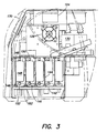
- FIG. 3 is a cross-sectional side view of a portable air monitoring unit
- FIG. 4 is a front perspective view of a sensor card
- FIG. 5 is a perspective view of a shroud used on a sensor card
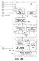
- FIG. 6 is a schematic block diagram of an expert system
- FIG. 7A and 7B is a schematic block diagram of an air monitoring system
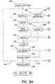
- FIG. 8A and 8B is a schematic block diagram of an air monitoring system including a grab sampler
- Referring to:FIG. 1A and 1B, a schematic block diagram of one embodiment of an
air monitoring system 100 according to the present invention is shown. The air monitoring system may be a portable or an installed system, or a system having a combination of portable and installed components. Theair monitoring system 100 includes anair monitoring unit 102. In a portable system, theair monitoring unit 102 may be hand held of reasonably portable. The air monitoring unit includes asensor unit 103 having at least onesensor 104 and acontrol unit 106. In a portable system the air to be sampled, orsample locations 108, may be taken from the area immediately surrounding the air monitoring unit or through a tube (not shown) from one or more remote sample locations. - An installed system may have many different configurations. The installed system may include an
air monitoring unit 102 installed in a building to monitor one or more spaces within the building. Referring to Fig. 2, the installed system may use one ormore sensor units 110 to monitorsample locations 108, where eachsensor unit 110 has one ormore sensors 104 for monitoring desired air quality parameters. Eachsensor unit 110 may, for example, have the configuration ofsensor unit 103 shown in Fig. 1 A and 1B. The sensor units may be distributed in desired locations inside the building. Thesensor units 110 connect through anetwork connection 112 to a central computer andcontroller interface control unit 116, which then connects to the central computer andcontroller controller network connection 112 used to connect the sensor units to the central unit may be a digital communication network of either proprietary design or open systems design such as a Lonworks or BACNet protocol. Thenetwork connection 112 may also be part of a building control network or part of an Ethernet system used for the building's information system communication network. A twisted pair network, an optical fiber, a power line, or wireless technology may be used for implementation. - FIG. 1A and 1B shows an implementation of the
air monitoring system 100 where onesensor unit 103 is connected to controlunit 106 through asensor interface card 122 without need for a distributed digital network. This approach may be used for a portableair monitoring unit 102 to monitor onesample location 108, or may be used in an installed system to monitormany sample locations 108 with the addition of extra installed equipment that brings air from multiple sample locations to theair monitoring unit 102 in sequential fashion. A star based system of tubes and centrally located solenoid valves may be used to sequentially pull air samples from remote sample locations to the air monitoring unit. Alternatively, a networked air sampling system, as described inU.S. Patent No. 6,125,710 , may utilize a central backbone with branches to route multiple packets of air from multiple sample locations through the same backbone. Distributed switches, such as air solenoid valves, in the branches are controlled by a digital control network to bring air samples through the common backbone tube to the air monitoring unit, such that the packets of air may be monitored by thesensors 104 and thecontrol unit 106 may store the air quality parameter data generated by the sensors. - For both the portable and the installed implementations, the
air monitoring system 100, including thecentral unit 106 and thesensor unit 103, may be used in a portable fashion and may be moved from building to building to monitor different buildings or structures over time on either an as needed or on a periodic basis. For the installed system of Fig. 2, the central computer andcontroller 118 may be moved from building to building, and the distributed system components, such as thesensor units 110, may be installed permanently or semi-permanently. Typically in the system of Fig. 1A and 1B, theair monitoring unit 102, including thesensor unit 103 and thecontrol unit 106, may be moved from building to building, and the tubing and controls may be installed permanently or semi-permanently. As a consequence, at least thecontrol unit 106 of Fig. 1A and 1B, and the central computer andcontroller 118 of Fig. 2 may need to be reprogrammed and customized whenever the device is used to monitor a different building. - Referring to the
air monitoring unit 102 of FIG. 1A and 1B, the air to be sampled is first brought into amanifold 124. The manifold is an air conduit inside thesensor unit 103. Frommanifold 124, the air is routed to one ormore sensors 104. The air may be routed usingswitches 342, such as solenoid valves or pumps or other such devices. As shown in FIG. 1A and 1B, the manifold itself may contain sensors, such as on amanifold sensor card 126, to measure environmental or air quality parameters, such as temperature, humidity, barometric pressure or ozone level, which can change after the air enters the air monitoring unit . For example, as the air travels through the air monitoring unit the temperature may increase or ozone may react with the walls of the tubing in the unit, thereby reducing the accuracy of the measurement. These parameters are preferably measured soon after the air is brought into theair monitoring unit 102. - From the manifold, air may be routed to
various sensors 104. As shown in Fig. 1A and 1B, the air is routed to into aradon detector 128, aparticle detector 132 and agrab sampling unit 130. Theradon detector 128 may be a continuously detecting instrument that may use one of various methods for detecting the presence of Radon gas. One possible method is to trap air particles that may be contaminated by the Radon gas in a piece of filter paper next to a radiation softened DRAM memory chip. Daughter decay elements from the Radon gas that are trapped in the filter paper emit alpha particles into the memory chip. This memory chip is filled with data and any changes in the state of the data indicate that an alpa particle has hit the memory chip. The number of counts of these alpha particles over time gives a reading of the amount of Radon gas present in an area. Alternative approaches for measuring radon gas continuously, such as with Geiger detector type systems or other approaches, may also be used. - The
particle detector 132 may use particle sensing or particle counting technology. Particle sensing systems are based on measuring air parameters that give an indication of the total mass of the particles in the air. Such systems may be based on ionization detectors as mentioned inU.S. Patent No. 5,982,690 or mass based light scattering approaches, such as the DataRAM product manufactured by MIE Instruments of Bedford MA. These products have been used in multiple parameter sensing instruments as mentioned in the above patent. Although these sensors are useful, it is becoming more apparent that from a health and safety standpoint that the number of particles, and in particular the number of fine particles under 2.5 microns, in size may be more relevant for indoor air quality measurements, since the smaller the particle the deeper into the lung the particle will go and the greater its potential health impact. In fact, recent medical! studies have correlated the presence of large numbers of fine particles with increased occurrences of heart disease. Particle counting sensors are used to count the number of particles of a given size and can discriminate between different sized particles. As such, they are potentially more useful for indoor air quality monitoring in comparison to total particle mass sensors. Particle counting detectors typically operate by sending a small high speed stream of air through the beam of a laser diode. Light that is scattered, reflected or refracted by any particles in the subject stream of air is collected by various mirrors and optics and then measured by a sensitive light detector. The amount and magnitude of the pulses of light from the detector may then be used to count and sort the sizes of particles in the air stream. Other techniques may also be used to count the quantities of various size particles. Other sensors are available to count ultra-fine particles of size less than 1 microns such as the P-Track Model 8525 from TSI Inc. of St. Paul, MN. - The
grab sampling unit 130 may include filter cartridges to capture particulate material and/or sorbent tubes to capture Volatile Organic Compounds (VOC's). Additionally, thegrab sampling unit 130 may store air in Suma canisters, Tedlar bags or other inert storage canisters. The operation of thegrab sampler unit 130 is explained in further detail below. Any type of sensor may be used insensor unit 104, although as mentioned below sensors that use particles as part of the measuring process are preferably placed next in the air sampling path. - The air sample may be routed through only one sensor, no sensor via the
bypass 343, which may include aswitch 342, such as a solenoid or a pump, or may travel simultaneously in parallel through two or more sensors as controlled by theswitch 342 as commanded by the central computer andcontroller 162. Since the radon and particle detectors' and grab sampling units' measurements are preferably based on a known quantity of air passing through the sensor, that the air flow may be accurately controlled through these sensors. Consequently anairflow sensor 344 may be used in series with the pump to measure the air monitoring unit's airflow. The pump's air flow rate can then be controlled via a variable speed pump control or some variable damper, orifice, or restriction device. The central computer andcontroller 162 or some other control unit such as an analog control circuit, located for example on thesensor interface card 122, may also be used to control the pump's airflow rate. If the pump's air flow rate is controlled and the flow rate is controlled through only one of thesensors 104, then their air flow rate is controlled. Moreover, if the air flow passes through two sensors simultaneously the split of air flow between these sensors may need to be fixed through some restrictive and potentially adjustable orifices or other flow adjusting device to accurately adjust the split of air between the two sensors. In this latter case, the air flow of the pump may be increased to set the air flow through these devices if two or more devices are operating in parallel. Alternatively, flow controlled pumps may be used for theswitch 342 for controlling flow rate individually through each of thesensors 104. This flow rate control and balancing is not critical for thegas sensors 134 since their measurement is much less dependent on the flow rate through them. - Typically, the radon detector, particle detector or counters, and the grab sampling units are the next sensors to come in contact with the air sample after the manifold sensor and, since these sensors are detecting particulate matter in the air and fewer bends may avoid trapping and losing particles before these sensors. Additionally, filter 341 may be used in front of the
gas sensors 134 to protect these sensors from being fouled by dust. Thus, these particle related sensors are typically provided in front of the gas sensors and dust or particulate filters. Additionally, these three types of sensors are not typically placed in series with each other. The air may pass through the particle detector, however some of the particles may be temporarily captured in the particle detector itself and released over time. Also, any bends in the tubing between sensors could cause particles to be lost in the tubing. - Air from the
radon detector 128,particle detector 132 and/or thegrab sampling units 130 may then pass intoadditional gas sensors 134, or the air may come directly from the manifold 124 to thegas sensors 134. Thegas sensors 134 may include one or more sensors to detect gases such as carbon monoxide, carbon dioxide, Total VOC's (TVOC's), Nitric Oxide (NO), Nitrogen Dioxide (NO2), Ammonia, air acidity or alkalinity, specific VOC's such as formaldehyde, or any other gases that are of interest to the user of the system. After passing through the gas sensors, the air may pass through afilter 136, such as a HEPA particle filter or a gas filter, to remove hazardous or undesirable gases. Lastly, the air exits the system through anexhaust 138. Avacuum pump 140 may be used to pull air through the air monitoring unit. - An optional feature of the air monitoring unit described above is the use of a sensor bay or
card cage 141 having removable cards to allow the easy and rapid reconfiguration of the air monitoring unit by a user to customize the air monitoring unit for a specific location or building. For example, a laboratory building requires different sensors, such as an air acidity sensor, from a classroom building where carbon dioxide is of greater importance for ventilation measurements. Preferably, a closed air path is provided to the sensors to minimize response time and to maintain sample integrity as the air moves through the air monitoring unit. As shown in FIG. 3, acard rack 142 is used to holdsensor cards 144. The sensor cards slide into the rack viaslots 146 and are easily removable. - A sensor may include a
sensing element 154 that is exposed to the air being monitored andsensor circuitry 155 or other components required for operation of the sensor. As shown in Fig. 4, thesensing element 154 and thecircuitry 155 may be mounted oncard 144.Sensor circuitry 155 may provide sensor signals to the central controller through aconnector 158. Ashroud 148 may be provided that substantially covers thesensor element 154 and defines an air flow path. Theshroud 148 preferably has anintake port 150 and anexhaust port 152 to allow air flow through the shroud. Theshroud 148 may form an air tight enclosure around thesensing element 154 to form a closed air path. Quick disconnect ports may be provided for the intake andexhaust ports screen 156 or perforated plate may be mounted withinshroud 148 to create a pressurized volume at the intake port that produces a laminar flow across thesensing element 154 to theexhaust port 152. The laminar flow from the intake end of theshroud 148 to the exhaust end creates a displacement ventilation effect and minimizes dead spots and recirculation inside the shroud. Air contaminants are thus flushed through theshroud 148 with minimal retention or capture by the shroud. - The removable sensor cards may use a standardized interface protocol and
cable connector 158 as shown in FIG. 4, such that the cards can be quickly replaced in the air monitoring unit. To facilitate rapid setup of the unit, the information describing the type of sensor or multiple sensors on the card, in addition to calibration information and other pertinent information about the card can be stored on the card itself in nonvolatile memory. In this manner, the central computer andcontroller 162 through thesensor interface card 122 can immediately recognize and start taking data from the sensor card without need for user interaction or setup programming. - In a preferred embodiment, the
sensor bay 141 includes asensor interface board 122 in Fig. 1A and 1B to support electrical connections for the sensor cards within the sensor bay. The sensor interface board may recognize any sensor card that is plugged into the sensor bay. The sensor card may include configuration information, such as sensor type and calibration. The configuration information may be stored in an EEPROM on the sensor card, such as Microchip Technology's 25C320 EEPROM. Use of a computer for the sensor bay may not be necessary when using the EEPROM. The sensor interface board may read the configuration information in order to recognize the sensor and properly interface with the sensor card related sensor data interface. The configuration information and the sensor data interface are accessed using a serial bus connection, such as an SPI, provided at the connection of the sensor cards to the sensor bay. - A pin connector, provided at the electrical connections, may be used to connect the sensor cards to the sensor bay for power and communications purposes. A control pin on the pin connector may be a power enable pin. The logic signal provided on the control pin may be used to selectively enable power to be applied to the
sensor circuitry 155 on each sensor card. Thus, the application of power to the sensors may be controlled, for example for power efficiency purposes. If the unit is operated on battery power, conservation of power may be useful. Moreover, some sensors may dissipate a relatively large amount of power, and it may not be desirable to run those sensors continuously. Furthermore, ambient temperature within the air monitoring unit may be reduced by selectively running the sensors. Power to each sensor may be controlled individually. The sensors may be turned on as needed and/or may be turned on at certain time intervals, such as every one or five minutes. Moreover, power to the sensor may be turned off and/or reduced to a lower level of consumption as desired. - Referring to FIG. 1A and 1B, the
control unit 106 stores the air quality parameter data measured by the sensors. Thecontrol unit 106 may also convert analog sensor data to digital data for storage. As shown in FIG. 1A and 1B, asensor interface card 122 may be used to convert the analog data to digital data for storage. Thecontrol unit 106 preferably includes la central computer andcontroller 162 that controls the functions of theair monitoring unit 102. Those functions may include, but are not limited to, controlling the flow of air throughsensor unit 103 and acquisition of sensor data, storage of sensor data in some type of nonvolatile memory or storage media, processing sensor data to provide air quality information and communicating with a remotely located control center, such as awebsite 166. Alocal display 170 may be provided on theair monitoring unit 102. Preferably, thedisplay 170 includes a touch screen, such that the user can input information into the control unit. - The
air monitoring unit 102 performs data logging while keeping track of different locations of an air sampling sequence. A sampling sequence may be preprogrammed into theair monitoring unit 102. A preferred method of tracking the locations associated with the data logging process is to rely on the user of the air monitoring system to specify the locations before starting a sampling sequence. To enable this function to be performed in an intuitive way, the air monitoring unit is configured in advance with various customized user data. The customized data may be obtained when the user opens an air monitoring system account, such as throughwebsite 166. The website is designed to coordinate the user's account with the data that is communicated from theair monitoring unit 102 to the website. Data sent from theair monitoring unit 102 to thewebsite 166 may include sensor data, air quality information derived from the sensor data, location data and/or any other data required for operation of the system. - The portable
air monitoring unit 102 may incorporate a Global Positioning System (GPS)system 176. This allows the precise location of theair monitoring unit 102 to be determined. Use ofGPS system 176 eliminates the need for the operator to input the air monitoring unit location each time the air monitoring unit is moved or to program a sequence of locations. Once the operator tells the unit the name of a given location the computer can correlate that name with GPS location information for that location so that subsequent testing of that location will be identified with it's appropriate name and data location. As a result, the monitoring location information is used to customize the air monitoring system, such that the resulting information from future testing of that location is associated with the specific building or room that is being monitored without need for further user input. - The
air monitoring unit 102 may be connected to a local network or to theInternet 178. The connection of theair monitoring unit 102 to the Internet can be achieved in several ways using various communications control andmedia interface 168 interacting withvarious communication media 180. A local connection into the building's data network, assuming the building has such a network, may be used. A common network in use within commercial facilities is an Ethernet system running at 10 MHz or more. Assuming this network has a connection to the Internet, the network may be used for access to the Internet. Another method is a local wireless connection involving a 900 MHz spread spectrum or other transmission technique commonly used in cordless phones. This technique utilizes a base unit transceiver that connects to a local phone line and another transceiver in theair monitoring unit 106. When the air monitoring unit needs to send or receive data, the unit checks the phone line to determine if it is busy, and if not the unit makes a call and sends or receives data through a local Internet Service Provider (ISP). Another method is to use a cellular phone to directly access a local or remote ISP. Finally, the air monitoring unit may connect to a building control system, which is connected to the Internet to provide data to the building control system for use by this system and to connect to the Internet. It will be understood that any method of connection to the Internet may be used. - As shown in FIG. 1A and 1B, the
website 166 includesremote web servers 182, adatabase 174, website programs andpage generation software 172 and anexpert system 186. Thewebsite 166 stores the air quality parameter data in thedatabase 174 for recordkeeping and/or analysis. The data may be published onwebsite 166 for access by the user via the account that the user sets up through the website and accesses through a computer andweb browser 184. - The Internet may be used to download information to the
air monitoring unit 102 to initialize or modify its program, operation, and/or setup based on specific information obtained about the building, its occupants, its surrounding environment and known or suspected problems. This customization of the unit may be achieved byexpert system 186 located remotely inwebsite 166 or, alternatively, in the air monitoring unit. Preferably, customization of theair monitoring unit 102 is achieved through the Internet. This aspect of the invention may involve the user answering questions about the building on the website. In particular, the user may utilize auser computer 184 to accesswebsite 166. The website may present to the user a series of questions, possibly determined byexpert system 186, which permit theair monitoring unit 102 to be customized for a specific application. The questions may be a fixed set of questions, or questions later in the session may be modified depending on answers given earlier in the session. The information obtained from the user may be used to create a customized monitoring program to analyze a specific building. The program is downloaded from thewebsite 166 through theInternet 178 via thecommunications media 180 and communications control andmedia interface 168 into the memory of the central computer andcontroller 162 to control its operation. - The
expert system 186 may generate programs and parameters for operating the air monitoring unit and may analyze the results of the measurements with respect to a specific building or room. The expert system includes a program or a combination of programs that uses rule based, case based or pattern recognition methods, or a combination of these methods to analyze data and make decisions and recommendations based on user supplied information, environmental data, such as weather, and measured air quality parameter data. Alternatively, or in addition, the expert systems, sometimes referred to as artificial intelligence (AI) systems, may use fuzzy logic, neural networks or other AI techniques to analyze data or make decisions. The basis of the rules on which the expert system is founded may be a combination of knowledge supplied by experts or by experience that the expert system achieves through feedback as to the accuracy of its analysis or decisions. - The expert system may capture and automate the knowledge necessary to diagnose indoor air problems and to recommend solutions to those problems. The expert system, using reported complaints, may diagnose likely causes and possible remedies. The expert system may also assess the likelihood of complaints in the future, given the attributes of a building. The expert system, using a prior diagnosis, may recommend a testing/monitoring regime to improve or corroborate the prior diagnosis. Moreover, the expert system may use previous diagnoses and recommendations to provide an audit trail of feedback from the user as to the effectiveness of the expert system's conclusions and may factor this information into future diagnoses.
- The expert system may accept different kinds of input, such as human observations and data transmitted from the air monitoring unit. Human observations may include information entered into the user's account. The expert system may function with either or both types of input.
- Referring to Fig. 6, a flow chart of one embodiment of the expert system is shown. The
expert system 186 is designed to act in a manner similar to a professional consultant. The expert system may proactively monitor 188 a structure for indoor air problems by controlling theair monitoring unit 102. Theexpert system 186 may also reactively diagnose 190 indoor air problems as suggested by symptoms disclosed by the user or occupant When the expert system is operating in a proactive mode, data from the air monitoring unit may be utilized in the analysis. In contrast, information regarding symptoms may be more important in the reactive mode. The proactive and the reactive methodologies lead to diagnoses and recommendations. These activities are followed by an audit trail activity in which users report on the effectiveness of the recommendations. This feedback may be used to track user satisfaction and/or to provide input to an automated learning mechanism in the expert system. User records may be updated to reflect the inputs, diagnoses, recommendations, and feedback for an entire session. - The
expert system 186 may configure theair monitoring unit 102 for testing a building or structure. Configuration regime variables include which rooms to monitor, the total number of rooms/floors to monitor, duration of sample collection, and whether allergen or special purpose tests should be conducted. Theexpert system 186 may recommend differential weightings on the different sensors. For example, theexpert system 186 may recommend that certain sensors be given more airflow or sampled more frequently than others. - With either a proactive or a reactive methodology, the user first orders an indoor air analysis such as through the
website 166 instep 192. When theexpert system 186 is used in the reactive mode, a user or occupant may report symptoms instep 194, and then the expert system may generate a report issuing a preliminary diagnosis instep 196 on the likelihood that indoor air quality is causing those symptoms, as opposed to organic or other causes. Theexpert system 186 may also report the likelihood of specific kinds of causes, e.g., VOCs, Fungi, etc. Although symptom information drives the preliminary diagnosis ofstep 196, information about building characteristics, occupant characteristics, ongoing activities within the building, recent events and surrounding context can also be used. This information may be generated by having the user answer questions when opening their user account. Theexpert system 186 then suggests issues to be looked at instep 198 to help verify preliminary hypothesis generated instep 196. Sensor data is automatically analyzed relating to these issues instep 200, and anintegrated diagnosis 202 is generated instep 202. Once the integrated diagnosis is generated, recommendations are made instep 204 for improving air quality in the building being analyzed. - The
expert system 186 may also be used when symptoms aren't being experienced by building occupants. The expert system may provide a forecast of the future likelihood of indoor air-related symptoms within the building, given relevant information such as building characteristics, occupant characteristics, ongoing activities, events, and context. - In the proactive mode,
expert system 186 may recommend a test configuration and procedure instep 210 that defines among other aspects, which areas to be tested, for how long, with what sensors, and under what conditions. In particular, the expert system triggers the taking of grab samples. The air monitoring unit may then issue a preliminary diagnosis instep 212 based on sensor air quality parameter data received from theair monitoring unit 102, and theexpert system 186 suggests issues to be looked at instep 214 based on analysis of the sensor air quality parameter data. The user may enter data regarding the occupants of the building and the building itself instep 216 and an integrated diagnosis is performed instep 218. The expert system then makes recommendations instep 204 for improving air quality in the building being analyzed. - The
expert system 186 may receive feedback instep 206 on the effectiveness of its prior diagnoses insteps step 204. The user's record is then updated instep 208. This feedback instep 206 may allow theexpert system 186 to track a user over time and to therefore provide "customized" servicing of that user. Moreover, this feedback may drive an AI-based learning mechanism in which theexpert system 186 alters its processing based on an assessment of its previous decisions. - The
expert system 186 may contain many kinds of knowledge. One kind of knowledge the expert system may have is knowledge of theair monitoring unit 102 from which the expert system receives air quality parameter data. Since theexpert system 186 knows about theair monitoring unit 102, the expert system may detect anomalies in the air monitoring unit and recommend self-checks on the air monitoring unit. - Sensor-driven air monitoring units, even when functioning perfectly, may occasionally send erroneous data. The expert system may be designed to know what kinds of data should be received and to detect when anomalous data is present. It is also possible for users to "game" the air monitoring unit, e.g., by breathing into it or by sending cigarette smoke directly into it. The expert system may be able to detect these kinds of situations as well. When the expert system detects tampered or faulty data, the tampered or faulty data may be discarded. If data is missing, the missing data may be filled in with average values or ignored.
- Referring to Fig. 7A and 7B, the
expert system 186 is shown connected to thecontrol unit 106 of theair monitoring unit 102. As shown, the expert system may be provided locally within the control unit. - The expert system may be "self-contained". The expert system may be embedded within a series of web pages, but still may not be part of the main website and may be a mini-website relative to the main site. The mini-website of the
expert system 186 may have its own IP address and may be invoked directly from a Web browser. Preferably, controls may be put in place to prevent the mini-website from being accessible under normal circumstances. Instead, it is preferable that users interact with the main website and request expert system services as desired. One or more databases may support the expert system. The databases may hold data regarding an occupant, a building, current and historical air monitoring data and previous diagnosis, recommendations and user feedback, as well as other associated variables pertaining to a user. - The expert system may use any type of reasoning apparent to one of skill in the art, such as deductive reasoning, reasoning by analogy and fuzzy reasoning over patterns. With deductive reasoning, the expert system may infer the likelihood that various indoor air problems exist, given user data. Deductions may occur along a chain of "if-then" rules, the rules being the standard form of knowledge representation within expert systems. When using reasoning by analogy, the expert system may consult a database of standard Indoor Air Quality (IAQ) cases and find those cases that are similar to that of the user. This kind of reasoning is called "by analogy" or "case-based" and the knowledge that underlies it "cases". With fuzzy reasoning over patterns, the expert system may consult a library of anomalous patterns and compare those patterns to the air quality parameter data and grab samples. IAQ problems are inferred to exist within the data to the extent that the anomalous patterns fit the data. Perfect fits are not expected. The degree to which the patterns fit the data using techniques of fuzzy set theory are assessed.
- All three types of reasoning or expert may exist separately or together for a given user. Each type of reasoning results in a probabilistic assessment of IAQ problems within user and sensor data. The results of each assessment under each type of reasoning may be combined into an overall assessment. This integration occurs via an AI architectural technique known as "Blackboarding". A blackboard is an event-driven data structure. The purpose of the blackboard is to allow each of the three reasoning methods to "post" its intermediate results to a common locale. In this way, each reasoning method can use the results of the other two methods, if desired. Other reasoning methodologies may be added to the expert system.
- The
expert system 186 may use the Web session as the "Blackboard". Results from all the reasoning methodologies, which are commonly referred to as "experts" are posted to the Web session and are available for use by the other experts. Use of the Web session as the expert system blackboard is possible due to the use of AI libraries to model expertise, such that common I/O operations run across libraries, meaning that different experts can speak to each other even if they use different knowledge representation techniques. Objects may persist across Web pages, such that the blackboard persists throughout the Web session. The Web session may opportunistically poll experts for answers, based on the dynamic gathering of information - The expert system may employ the knowledge of multiple experts or reasoning methods. These experts, due to the different methodologies they employ, may bring a diverse set of perspectives to the problem of assessing air quality. Thus, the expert system may be designed to incorporate multiple, cooperating experts, each of whom is expert yet approaches the same problem in different ways. From a process standpoint, each expert may be assigned to work on the entire indoor air quality problem versus having a different part of the problem be worked by a different expert or methodology.
- The exact sensor patterns that are diagnostic of IAQ problems may be revealed from the data itself and added to the library of anomalous patterns that are specified analytically. To effect this, the expert system may contain a data mining capability. User data, such as air quality parameter data, may be mined for significant patterns, and when such patterns are deemed to exist, they may be incorporated into the live expert system. Typically, this would not affect the use of the expert system, such as having to shut the system down to rebuild. Data that has previously been compared to the expert system pattern library may be reanalyzed with new patterns, making the system appear smart as well as providing new insights into nagging customer problems.
- Data mining is typically coupled with a learning mechanism. The expert system may mine for all new patterns but may only "learn" those patterns that are diagnostic of indoor air problems. For example, the audit trail facility in which users give feedback on prior diagnoses in
step 206 acts as a "teacher". In other words, the expert system may mine for new patterns and may correlate all mined patterns with feedback given by users. Mined patterns that are correlated with assertions of "good" diagnoses may be learned, while patterns that are correlated with feedback of "bad" diagnoses may be forgotten. The learning mechanism goes beyond sensor air quality parameter data patterns. In fact, all three kinds of knowledge-rules, cases, and patterns-may be learned over time. For each of the three types of knowledge, user feedback may act as a "teaching" mechanism. - The
expert system 186 may form the foundation of anIAQ scorecard 209. This scorecard may be analogous to the scorecards used by the mortgage industry. Within the mortgage industry, loan originators, the secondary mortgage market, and credit rating agencies all use scorecards to assess the credit worthiness of loan applicants. Scores produced by such scorecards are weighted combinations of credit attributes and therefore are a single number that represent credit worthiness. In a similar manner, an IAQ Scorecard may have a weighted combination of IAQ attributes. An example of an IAQ scorecard might include three subindices. The first may be a rating of comfort and ventilation using such parameters as temperature, relative humidity, and CO2. A second may be a measure of the healthiness of the space or conversely the level of pollutants or contaminants in the air. This measure may involve measurements of gases such as carbon monoxide, VOC's, allergens, mold, etc. A third area may be used to cover operational issues such as energy efficiency or the usage of outside air. These areas or others may be used individually or combined in some weighted manner to create a single number index. The attributes and their weights may be guessed at prior to collection of data but most likely will be determined empirically. As such, the expert system's data mining and learning capabilities may be critical to the construction of a scorecard that truly distinguishes "IAQ bad risks" from "IAQ good risks". Finally, the IAQ scorecard may also take the numbers that are generated and aggregate them with other similar numbers. After a large enough database is generated, each individual user's IAQ score can be compared to others to generate a percentile result of how the particular analyzed building or room compares to other buildings within the same area or across the country. Since there are no official guidelines on IAQ parameters, this kind of comparative analysis or score can be useful to know how a facility is doing relative to other similar buildings in providing good air to its occupants. The expert system may then also recommend approaches based on a low score that should allow a building's score to be raised. - One application of the
air monitoring unit 102 involves rental or lease to the general public, and this embodiment is discussed in detail below. Specifically, the application of a portableair monitoring unit 102 as shown in FIG. 1A and 1B is discussed. Over time, a unit may be assigned to many different users. Alternatively, one user who owns or rents the air monitoring unit may use it in multiple buildings or locations, or a service organization may use the air monitoring unit to provide indoor air quality audits for many different users. To support these functions, theair monitoring unit 102 may be designed to have its user information erased after each use. At the onset of commissioning, the air monitoring unit may contain only generic configuration information, such as sensor calibration data. Configuration data, such as information in the user's account database, may be downloaded to theair monitoring unit 102 once the unit is in the user's possession. This configuration information is preferably downloaded to the air monitoring unit via the Internet. Theair monitoring unit 102 takes on a "personality" that reflects the profile of the specific user's building and/or occupants. Any questions relevant to the evaluation of the indoor air quality for the building may be answered by the user on the website via the user'scomputer 184. The user's answers are located in the user's account, and are accessible by thewebsite program 172 andexpert system 186. Such questions may include questions about the building, the occupants and the building's surroundings. Many possible questions will be apparent to those of skill in the art. If the user is a homeowner, this configuration information may include customized room names assigned to a table of room numbers, as shown in Table 1 below.Table 1 Room 1: Basement Room 2: First Floor Bathroom Room 3: Sally's Room Room 4: Living Room Room 5: Kitchen Room 6: My Office Room Room 7: My Bedroom Room 8: My Bathroom - As air quality parameter data is transferred from the
air monitoring unit 102 to the user'saccount database 174 via theInternet 178, the data in the database may be associated with the customized names. This enables the user to easily interpret the data when viewing the data on thewebsite 166. Thewebsite 166 may generate customizedreports 203 on the user's indoor air quality that may be displayed on the website and may also be printed out in hard copy form off a printer. For example, if the data recorded forRoom 3 shows that VOC levels are high, a personalized report can be generated that specifically says "the VOC levels in Sally's room are high". - Another benefit of configuring the
air monitoring unit 102 with customized information is that it may substantially simplify the administration of the air sampling tests if the air monitoring unit is portable. Theair monitoring unit 102 presents to the user prompts that can be readily understood. For example, once the air monitoring unit is configured with the customized information, air sampling sequences can commence based on a predetermined script by room number. However, the user may be prompted based on the customized name assigned to each room number. Therefore, once the monitoring process forRoom 1, the "Basement", is complete, theair monitoring unit 102 can prompt the user to relocate the unit to the "First Floor Bathroom", orRoom 2. This enables theair monitoring unit 102 to be moved around the building in a relatively foolproof manner. If aGPS system 176 is included in the air monitoring unit, the GPS system can thereafter verify the location ofair monitoring unit 102 in a particular room. - The implementation of the
air monitoring unit 102 may be driven by the user's account, which is established by the user via the internet. Because the air monitoring units that may be rented will serve numerous customers, it is preferable that the method used to transfer the air quality parameter data to the user's account be highly reliable and secure. This may reduce the possibility of the accidental transfer of data to the wrong account, such as the account of the previous user. A preferred way of achieving reliability and security is to supply the user with a unique I.D. number after they open a user account via the Internet. This I.D. number is input into theair monitoring unit 102 by the user before the air monitoring unit accesses the Internet to obtain the personalized data from the user's account. An account name may be included with the I.D. number to further reduce the potential for accessing the wrong user account. Encryption of the communication between theair monitoring system 102 and thewebsite 166 can provide additional security. - Since one of the basic functions of the air monitoring unit is to periodically and automatically upload sampled air quality parameter data to the user account via the Internet, the mechanism by which the unit accesses a phone line should be highly flexible. The data transfer process to the Internet is preferably transparent to the user, as it would be highly inconvenient for the user to be manually involved in the process, given the frequency of the activity. The data transfer process may occur once an hour, or more or less frequently, depending on the nature of the application. One reason for such frequent data transfer is that the air quality parameter data may be used to provide rapid feedback to the user. A rapid response in the presentation of air quality parameter data from the
air monitoring unit 102 can be useful when the user is trying to determine the effectiveness of a change being implemented to remedy an air quality problem. For example, the user may want to assess the effectiveness of the application of a portable air cleaner to a room in the building. - To support the transparent transfer of data to the Internet, a preferred embodiment of the
air monitoring unit 102 includes a wireless data link to a phone line. Alternatively, a wireless data link to a building Local Area Network may be used. The method involves a second unit, the Telephone Base Unit (TBU) which is designed to physically connect to a phone jack and to provide 900MHz wireless communications to theair monitoring unit 102. This allows the air monitoring unit to "dial out" any time the phone line is available, while the unit is located in the building under evaluation. - In order to initially configure the
air monitoring unit 102, the user plugs the air monitoring unit into a power source. The air monitoring unit may be battery powered. The user would also connect a power source to the telephone base unit 171 (TBU), if it is not battery powered. At this point, when the air monitoring unit and TBU are being configured for use, the user may connect the TBU to an available phone line. As is the case with most modems, the TBU may have an RJ11 jack to allow the phone line connection to be shared between the TBU and some other device, like a telephone. - The user initiates a Test and Configuration Mode via the air monitoring unit
touch screen display 170. Theair monitoring unit 102 tests communications locally between the air monitoring unit and the TBU. When the phone line is free, the TBU dials out via a toll free number to an Internet Service Provider. Theair monitoring unit 102 sends the unique I.D. number for the user and links to the customer's database on thewebsite 166. Thewebsite 166 downloads information, such as a program and parameter information, so as to configure theair monitoring unit 102 for performing a test or a series of tests in a specific building. Thereafter, the commissioning process is complete, and theair monitoring unit 102 is ready for use. The user places the air monitoring unit in a desired location and selects the room to be tested using the touch screen display. The unit may verify the signal strength, and the unit may be relocated if the signal is poor. Alternatively, the unit may store air quality parameter data for later uploading to the Internet when the unit is moved back within range of the TBU. An Air Sampling Mode is initiated, and local data is displayed on the touch screen display. Air quality parameter data is transferred to thewebsite 166 on a periodic basis, such as once per hour or as frequently as desired, and the air monitoring unit may be reconfigured or information may be downloaded to the unit. - The air monitoring system may be configured to capture samples of air based upon the detection of various events that may be associated with indoor air conditions. The capability of triggering the capture of an air sample at a precise moment is helpful to diagnose and eventually resolve an indoor air quality problem, as these problems are often transient in nature.
- As shown in FIG. 8A and 8B,
air monitoring unit 102 includes a continuous or periodically sampledair parameter sensor 220 and grabsampler 130. The taking of a sample bygrab sampler 130 may be triggered by theair monitoring unit 102 itself, based on monitoring by theair parameter sensor 220. Alternatively, theair parameter sensor 220 may be monitored by thewebsite 166 through the Internet. A command transmitted from thewebsite 116 through theInternet 178 to theair monitoring unit 102 triggers the capture of an air sample so that a more detailed analysis of the air quality parameter can be performed. In either case, the taking of the grab sample is triggered when the parameter sensed bysensor 220 meets a predetermined criteria. It will be understood that the criteria for triggering the taking of the grab sample can be based on measurements by two or more sensors and/or on other information. - One embodiment of the invention involves using a broad sensor, for example a sensor used to detect Total Volatile Organic Compounds (TVOC's), as the measurement device or the
air parameter sensor 220 from which the taking of a grab sample may be triggered. By monitoring such a sensor, a grab sample can be triggered based on the presence of any one of a large number of VOC parameters to which the sensor is sensitive and/or at a predetermined concentration. In such an application, the "grab sample" device may be a sorbent tube filled with Tenax-G or Carbosieve-3 absorption material. The sorbent tube may be removed from the grab sampler after a sample has been taken and sent to a laboratory for analysis. The results can then be put into the user's website account and the expert system used to analyze this information in the context of other collected data and information. - Another embodiment involves the capture of particulate matter, using a particle sensor as the
air parameter sensor 220 and a filter cartridge, auger plate, petri dish, "sticky slide" or particle impaction device as shown inU.S. Patent No. 5,693,895 , or other suitable device on which to deposit a particulate sample in order to capture a sample for analysis. This approach uses the particle sensor to track the concentration of particulates in the indoor environment. The criteria for triggering a grab sample may include concentrations above the average concentration, above a predetermined threshold value, and/or by way of decisions made by an expert system on various user supplied information, and real time data, such as particle concentration data from the sensor. Grab sampling of particulate matter is a practical way of testing for mold, bacteria, and other viables, as well as pollen, dander, and other types of allergens. As is the case with grab sampling using sorbent tubes, grab sampling for particulate matter using the trigger mechanism allows events to be captured as they happen. For example, mold within households can create miserable conditions for inhabitants, yet these conditions may be present for short periods of time based on fluctuations in humidity. Therefore, identifying a mold problem and the type of mold present can be difficult unless the symptoms are persistent. However, a trigger based sampling method that captures mold spores while still in flight may provide conclusive evidence of the problem. This is especially true, given the fact that the samples captured on the filter or auger plate can be analyzed by a laboratory to identify the concentration and species of mold, pollen, etc. that was captured. - More generally the concept of utilizing an
air parameter sensor 220 to trigger a grab sample may apply to any sensor deployed to monitor a parameter or parameters of interest and may involve any type of suitable mechanism to trap a sample. For example, the grab sample may utilize absorption material, filter media, a canister, a particle impaction device or an Auger plate, but is not limited to these devices.
Claims (30)
- An air monitoring system (100) for monitoring air quality at indoor locations, comprising:an air monitoring unit (102) including at least one sensor (104) for acquiring air quality parameter data at a selected indoor location in a building, the building having a plurality of spaces intended for use by humans; and a computer (182) that receives the acquired air quality parameter data, whereinthe computer includes an expert system (186) for controlling at least the acquisition of data by the air monitoring unit based at least in part on the acquired air quality parameter data, and the expert system employs at least one ofcharacterised in that the air monitoring unit (102) further includes a grab samples (130) for acquiring an air sample and in thati) a rule-based method,ii) a case-based method andiii) a pattern recognition method using fuzzy reasoning over patterns,
the expert system includes means for issuing a command to the grab sampler to acquire an air sample in response to acquired sensor data meeting predetermined criteria. - The air monitoring system of claim 1, wherein the expert system is adapted to analyse data from the air monitoring unit based at least in part on the acquired air quality data and reaching a conclusion regarding air quality of the selected indoor location.
- The air monitoring system of any one of claims 1 to 2, further comprising:a source of environmental data representative of the outside of a building in which at least one indoor location is being monitored;wherein the expert system is adapted to provide an air quality analysis based at least in part on the acquired air quality-parameter data and the environmental data.
- The air monitoring system of any one of claims 1 to 3, wherein the expert system is adapted to configure a test to be performed by the air monitoring unit including at least the location of the test and the time duration for the test.
- The air monitoring system of any one of claims 1 to 4, wherein the expert system is adapted to provide a recommendation for improving the air quality parameter data.
- The air monitoring system of any one of claims 1 to 5, wherein the air monitoring unit includes a program for acquiring the air sample and the expert system is adapted to modify the program.
- The air monitoring system of any one of claims 1 to 6, wherein the expert system is adapted to analyze the acquired air quality parameter data and reach a conclusion regarding air quality of the selected indoor location.
- The air monitoring system of any one of claims 1 to 7, wherein the expert system is adapted to analyze information representative of the selected indoor location in reaching the conclusion.
- The air monitoring system of any one of claims 1 to 8, wherein the expert system comprises at least two experts adapted to determine intermediate results and an expert coordinator adapted to combine the intermediate results to reach the conclusion.
- The air monitoring system of any one of claims 1 to 9 , further comprising:a communication link between the computer and the air monitoring unit, the communication link including a data communication network that is adapted to handle communications between the computer and the air monitoring unit;wherein the computer comprising the expert system is remotely located from said air monitoring system.
- The air monitoring system of claim 10; wherein the communications link includes a building's data network, a building control system network, and/or a local arca network.
- The air monitoring system of any one of claims 10 and 11, wherein at least a portion of the communications between the computer and the air monitoring unit is encrypted.
- The air monitoring system of any one of claims 1 to 12, wherein the computer comprising the expert system is remotely located from said air monitoring system with communications between the expert system and the air monitoring system that at least includes information related to the air quality parameter data acquired by the air monitoring system.
- The air monitoring system of any one of claims 1 to 9, wherein the computer comprising the expert system is a local part of the air monitoring unit.
- The air monitoring system of any one of claims 1 to 14, wherein said expert system can make a recommendation for improving the air quality of the selected indoor location.
- The air monitoring system of any one of claims 1 to 15', wherein said expert system modifies the operation of the grab sampler in response to the acquired sensor data.
- The air monitoring system of any one of claims 1 to 16, wherein said air monitoring system comprises a portable air monitoring unit that is easily movable to different selected indoor locations.
- The air monitoring system of any one of claims 1 to 17, wherein said air monitoring system comprises an installed system for monitoring air quality in multiple indoor locations.
- The air monitoring system of any one of claims 1 to 18, wherein expert system is used at least in part to detect anomalies in the air monitoring system and/or to detect tampered or faulty data.
- The air monitoring system of any one of claims 1 to 19, wherein the expert system operates at least on one of occupant symptom data from the-indoor location, user supplied information about the indoor location, or historical indoor air quality data in addition to current indoor air quality data from the indoor location.
- The air monitoring system of any one of claims 1 to 20, wherein the expert system can learn or improve its effectiveness by accepting user feedback on the effectiveness of its conclusions.
- The air monitoring system of any one of claims 1 to 21, wherein data mining is used to assist the learning process.
- The air monitoring system of any one of claims 1 to 22, wherein the expert system uses two or more of rule, case, or pattern recognition based methods and combines their results to create an overall assessment of the air quality parameter data.
- The air monitoring system of any one of claims 1 to 23, wherein the expert system uses blackboarding techniques to combine multiple expert system methods.
- The air monitoring system of any one of claims 1 to 24, wherein a web session is used as the expert system blackboard.
- The air monitoring system of any one of claims 1 to 25, wherein said expert system uses a rule-based method to process the air quality parameter data.
- The air monitoring system of any one of claims 1 to 26, wherein said expert system uses a case-based method to process the air quality parameter data.
- The air monitoring system of any one of claims 1 to 27 wherein said expert system uses a pattern recognition method using fuzzy reasoning over patterns to process the air quality parameter data.
- The air monitoring system of any one of claims 1 to 28, wherein said air monitoring unit includes a carbon dioxide sensor, a particle sensor and a humidity sensor.
- The air monitoring system of any one of claims 1 to 28, wherein said air monitoring unit includes a carbon dioxide sensor and a TVOC sensor.
Applications Claiming Priority (3)
| Application Number | Priority Date | Filing Date | Title |
|---|---|---|---|
| US779379 | 2001-02-07 | ||
| US09/779,379 US7302313B2 (en) | 2001-02-07 | 2001-02-07 | Air quality monitoring systems and methods |
| PCT/US2002/003689 WO2002063294A2 (en) | 2001-02-07 | 2002-02-07 | Air quality monitoring systems and methods using expert systems |
Publications (2)
| Publication Number | Publication Date |
|---|---|
| EP1390742A2 EP1390742A2 (en) | 2004-02-25 |
| EP1390742B1 true EP1390742B1 (en) | 2007-11-07 |
Family
ID=25116256
Family Applications (1)
| Application Number | Title | Priority Date | Filing Date |
|---|---|---|---|
| EP02713555A Expired - Lifetime EP1390742B1 (en) | 2001-02-07 | 2002-02-07 | Air quality monitoring systems and methods using expert systems |
Country Status (6)
| Country | Link |
|---|---|
| US (3) | US7302313B2 (en) |
| EP (1) | EP1390742B1 (en) |
| JP (1) | JP2005504947A (en) |
| AU (1) | AU2002245399A1 (en) |
| DE (1) | DE60223357D1 (en) |
| WO (1) | WO2002063294A2 (en) |
Cited By (3)
| Publication number | Priority date | Publication date | Assignee | Title |
|---|---|---|---|---|
| TWI498553B (en) * | 2012-03-01 | 2015-09-01 | Univ Nat Taipei Technology | Wireless air quality monitoring system and air quality predicting methods |
| DE102018214936A1 (en) * | 2018-09-03 | 2020-03-05 | Robert Bosch Gmbh | Portable optical particle sensor device and corresponding particle measurement method |
| DE102018216527A1 (en) * | 2018-09-27 | 2020-04-02 | Robert Bosch Gmbh | Method, device and computer program for operating a particle counter of a mobile terminal |
Families Citing this family (299)
| Publication number | Priority date | Publication date | Assignee | Title |
|---|---|---|---|---|
| US7302313B2 (en) * | 2001-02-07 | 2007-11-27 | Aircuity, Inc. | Air quality monitoring systems and methods |
| US6925422B1 (en) * | 2001-07-05 | 2005-08-02 | Airqual | System and method for monitoring the performance of an indoor air environment product installation |
| US6782351B2 (en) * | 2001-09-11 | 2004-08-24 | Purechoice, Inc. | Air quality monitoring and space management system coupled to a private communications network |
| US10161923B1 (en) * | 2001-11-09 | 2018-12-25 | Lawrence Factor, Inc. | Remote gas sample analysis and monitoring system with an onsite onboard gas analyzer calibration system |
| US9134284B1 (en) | 2001-11-09 | 2015-09-15 | Lawrence Factor, Inc. | Remote gas sample analysis and monitoring system |
| US7183115B1 (en) * | 2001-11-09 | 2007-02-27 | Lawrence Factor, Inc. | Gas sample analysis system |
| JP2003254593A (en) * | 2002-03-01 | 2003-09-10 | Yamatake Corp | Indoor environment declaration system and its declaring method |
| US7317969B2 (en) * | 2002-09-30 | 2008-01-08 | Ctb Ip, Inc. | Method and system for managing and operating a plurality of farm houses |
| AU2003286587B2 (en) * | 2002-10-24 | 2009-04-23 | Clean Air Filter | Method and apparatus for leak testing an environmental enclosure |
| US20080288224A1 (en) * | 2003-02-14 | 2008-11-20 | Schwartz Lawrence A | System and method for assessing mold risk propensity and dampness index in structure |
| US7241218B2 (en) * | 2003-05-06 | 2007-07-10 | Ruskin Company | Fire/smoke damper control system |
| US20050005677A1 (en) * | 2003-05-30 | 2005-01-13 | Smith Kirk R. | Method and apparatus for environmental monitoring and data logging |
| US6991029B2 (en) * | 2003-06-06 | 2006-01-31 | Orfield Laboratories, Inc. | Architectural dynamic control: intelligent environmental control and feedback system for architectural settings including offices |
| NZ526815A (en) * | 2003-07-03 | 2005-09-30 | Agres Ltd | A method of and means for detecting the presence of a biosecurity threat in a confined environment |
| GB2404021B (en) * | 2003-07-17 | 2006-02-22 | Ecameter Ltd | Emissions meter |
| JP4604603B2 (en) * | 2003-08-26 | 2011-01-05 | ダイキン工業株式会社 | ENVIRONMENT PROVIDING SYSTEM, ENVIRONMENT PROVIDING DEVICE, CONTROL DEVICE, AND ENVIRONMENT PROVIDING METHOD |
| US7205891B1 (en) | 2003-09-19 | 2007-04-17 | Purdue Research Foundation | Real-time wireless video exposure monitoring system |
| US7119676B1 (en) | 2003-10-09 | 2006-10-10 | Innovative Wireless Technologies, Inc. | Method and apparatus for multi-waveform wireless sensor network |
| JPWO2005055164A1 (en) * | 2003-12-04 | 2007-12-06 | 株式会社Snt | Environmental monitoring method and system |
| US7191097B1 (en) | 2004-03-31 | 2007-03-13 | United States Of America | Method, apparatus, and system for assessing conditions |
| US20050233063A1 (en) * | 2004-04-15 | 2005-10-20 | Weiler Jeff L | Coating operation pollutant emission measurement and recording system and method |
| US7536232B2 (en) * | 2004-08-27 | 2009-05-19 | Alstom Technology Ltd | Model predictive control of air pollution control processes |
| KR20070054720A (en) * | 2004-09-28 | 2007-05-29 | 다이킨 고교 가부시키가이샤 | Environment management device, environment management system, environment management method, and environment management program |
| EP1802967A2 (en) * | 2004-10-04 | 2007-07-04 | Food Quality Sensor International, Inc. | Food quality sensor and methods thereof |
| CN101164028B (en) * | 2005-03-04 | 2011-04-20 | 纯净选择公司 | Air quality monitoring method and system |
| WO2006099125A2 (en) * | 2005-03-10 | 2006-09-21 | Aircuity, Inc. | Dynamic control of dilution ventilation in one-pass, critical environments |
| FR2888128B1 (en) * | 2005-07-11 | 2007-10-12 | Maintenance Securite Installat | METHOD FOR CONTROLLING THE LEAKAGE RATE OF ACTIVE COAL FILTERS |
| US20080281528A1 (en) * | 2005-08-03 | 2008-11-13 | Relle Jr Louis J | System and Method for Environmental Sampling and Diagnostic Evaluation |
| KR101120325B1 (en) * | 2005-08-18 | 2012-03-08 | 엘지전자 주식회사 | Abatar refrigerator |
| US7956719B2 (en) * | 2005-09-29 | 2011-06-07 | Siemens Industry Inc. | Building control system communication system timing measurement arrangement and method |
| US7421911B2 (en) | 2005-12-20 | 2008-09-09 | Desrochers Eric M | Duct probe assembly system for multipoint air sampling |
| JP2009527838A (en) * | 2006-02-21 | 2009-07-30 | ジー.アール.ジー パテント リミテッド | System and method for assessing and reducing air pollution by regulating air flow |
| US7369955B2 (en) * | 2006-02-23 | 2008-05-06 | Homesafe Inspection, Inc. | Method for residential indoor environmental quality inspection and monitoring |
| US20080126533A1 (en) * | 2006-11-06 | 2008-05-29 | Microsoft Corporation | Feedback based access and control of federated sensors |
| US20080148816A1 (en) * | 2006-12-22 | 2008-06-26 | Groves Bruce D | Air monitoring system and method |
| US8485019B2 (en) * | 2006-12-22 | 2013-07-16 | Bruce D. Groves | Methods and systems for analysis, reporting and display of environmental data |
| US20090090167A1 (en) * | 2006-12-22 | 2009-04-09 | Groves Bruce D | Methods and Systems for Analysis, Reporting and Display of Environmental Data |
| US8762060B2 (en) * | 2007-01-30 | 2014-06-24 | International Business Machines Corporation | Pervasive network for environmental sensing |
| WO2008151285A1 (en) * | 2007-06-05 | 2008-12-11 | The Trustees Of Columbia University In The City Of New York | Systems and devices for collecting time and space resolved air samples |
| EP2017597A1 (en) * | 2007-07-16 | 2009-01-21 | Paradigm Services Limited | Monitoring device and system of monitoring devices |
| US7788294B2 (en) * | 2007-08-17 | 2010-08-31 | Graywolf Sensing Solutions, Llc | Method and system for collecting and analyzing environmental data |
| CA2704577C (en) * | 2007-11-05 | 2015-10-27 | Sloan Valve Company | Restroom convenience center |
| US8555721B2 (en) * | 2007-12-27 | 2013-10-15 | Scott Taillet | Sound measuring device |
| US7940188B2 (en) * | 2008-02-07 | 2011-05-10 | Veltek Associates, Inc. | Air sampling system having a plurality of air sampling devices with their own flow switches |
| US20120152040A1 (en) | 2008-02-07 | 2012-06-21 | Rosario Calio | System and method for air sampling in controlled environments |
| CN101970990A (en) * | 2008-02-15 | 2011-02-09 | 佐治亚科技研究公司 | Systems and methods for providing environment monitoring |
| JP5335346B2 (en) * | 2008-09-26 | 2013-11-06 | 三洋電機株式会社 | Cooling system |
| JP5258479B2 (en) * | 2008-09-26 | 2013-08-07 | 三洋電機株式会社 | Cooling system |
| US9325573B2 (en) * | 2008-12-09 | 2016-04-26 | Schneider Electric Buildings Ab | Building control system |
| US8054188B2 (en) | 2009-01-05 | 2011-11-08 | Utc Fire & Security Americas Corporation, Inc. | Carbon monoxide detector, system and method for signaling a carbon monoxide sensor end-of-life condition |
| EP2411881B1 (en) * | 2009-03-27 | 2013-08-14 | ABB Research Ltd. | System for controlling at least a parameter of ambient air |
| US8154723B2 (en) | 2009-04-03 | 2012-04-10 | Sharp Laboratories Of America, Inc. | Method and systems for particle characterization using optical sensor output signal fluctuation |
| WO2010120771A1 (en) * | 2009-04-15 | 2010-10-21 | DiMi, Inc. | Remote building monitoring and controlling system and method |
| US8427309B2 (en) * | 2009-06-15 | 2013-04-23 | Qualcomm Incorporated | Sensor network management |
| US8478603B2 (en) * | 2009-06-24 | 2013-07-02 | International Business Machines Corporation | Method and system for monitoring and reporting to an operator greenhouse gas emission from a vehicle |
| WO2011005353A1 (en) | 2009-07-06 | 2011-01-13 | Exxonmobil Upstream Research Company | Method for seismic interpretation using seismic texture attributes |
| US8330605B2 (en) * | 2009-08-14 | 2012-12-11 | Accenture Global Services Limited | System for providing real time locating and gas exposure monitoring |
| US8451120B2 (en) * | 2009-08-14 | 2013-05-28 | Accenture Global Services Limited | System for relative positioning of access points in a real time locating system |
| CA2805851C (en) | 2009-10-08 | 2017-03-07 | Adam K. Fontecchio | Led lighting system |
| US20110087524A1 (en) * | 2009-10-14 | 2011-04-14 | International Business Machines Corporation | Determining travel routes by using fee-based location preferences |
| US8812352B2 (en) * | 2009-10-14 | 2014-08-19 | International Business Machines Corporation | Environmental stewardship based on driving behavior |
| US20110087430A1 (en) | 2009-10-14 | 2011-04-14 | International Business Machines Corporation | Determining travel routes by using auction-based location preferences |
| GB0920315D0 (en) * | 2009-11-20 | 2010-01-06 | Univ Bristol | A diagnostic apparatus |
| CN102812501B (en) * | 2009-12-29 | 2015-11-25 | 加利福尼亚大学董事会 | Multimodal Climate Sensor Network |
| US8584509B2 (en) * | 2009-12-31 | 2013-11-19 | Emilcott Associates, Inc. | Environmental monitoring system and method with a prefilter |
| US9075016B2 (en) | 2009-12-31 | 2015-07-07 | Emilcott Associates, Inc. | Automated control of analytical sampling with environmental monitoring system |
| US20110166958A1 (en) * | 2010-01-05 | 2011-07-07 | International Business Machines Corporation | Conducting route commerce from a central clearinghouse |
| EP2524201A1 (en) * | 2010-01-12 | 2012-11-21 | Fiducie Aeternum | Fluid sampling system |
| US9645112B2 (en) * | 2010-01-19 | 2017-05-09 | R2Cd Holdings Pte Ltd. | Auto-cleaning and auto-zeroing system used with a photo-ionization detector |
| DK2537148T3 (en) | 2010-02-18 | 2021-09-27 | Veltek Ass Inc | IMPROVED AIR SAMPLING SYSTEM |
| US20110218691A1 (en) * | 2010-03-05 | 2011-09-08 | Efficient Energy America Incorporated | System and method for providing reduced consumption of energy using automated human thermal comfort controls |
| US10021466B2 (en) * | 2010-04-01 | 2018-07-10 | FW Murphy Production Controls, LLC | Systems and methods for collecting, analyzing, recording, and transmitting fluid hydrocarbon production monitoring and control data |
| US10962678B2 (en) * | 2010-04-01 | 2021-03-30 | FW Murphy Production Controls, LLC | Systems and methods for collecting, displaying, analyzing, recording, and transmitting fluid hydrocarbon production monitoring and control data |
| US8594938B2 (en) * | 2010-04-01 | 2013-11-26 | Fw Murphy | Systems and methods for collecting, analyzing, recording, and transmitting fluid hydrocarbon production monitoring and control data |
| US8777171B2 (en) | 2010-04-06 | 2014-07-15 | Smart Air Technologies Llc | Airborne particle and microorganism collection system |
| TW201215871A (en) * | 2010-05-14 | 2012-04-16 | Access Business Group Int Llc | Hand held particle sensor device |
| GB2481214B (en) * | 2010-06-15 | 2013-01-02 | 4Energy Ltd | Air flow measurement |
| ES2377684B1 (en) * | 2010-06-25 | 2012-11-23 | Ingenieros Asesores, S.A. | SYSTEM OF MONITORING OF ENVIRONMENTAL PARAMETERS IN CONTINUOUS AND METHOD ASSOCIATED WITH THE SAME. |
| FR2962193B1 (en) | 2010-07-01 | 2012-08-24 | Somfy Sas | METHOD FOR CONTROLLING AT LEAST ONE MOTORIZED MEANS OF NATURAL VENTILATION OF A LOCAL ACCORDING TO A QUALITY OF THE AIR MEASURED IN SAID LOCAL, AND DEVICE FOR IMPLEMENTING SAID METHOD |
| US8683645B2 (en) | 2010-07-22 | 2014-04-01 | Sears Brands, L.L.C. | Vacuum cleaning device with air quality monitoring system |
| FR2963676B1 (en) * | 2010-08-05 | 2012-09-28 | Veolia Water Solutions & Tech | DEVICE FOR SAMPLING AN AMBIENT AIR BULB |
| WO2012023136A1 (en) | 2010-08-15 | 2012-02-23 | Airbase Systems Ltd. | Device, system and method for personal health monitoring based on multitude-points environmental data |
| US9322568B2 (en) | 2010-10-07 | 2016-04-26 | Field Controls, Llc | Whole house ventilation system |
| WO2012054643A1 (en) * | 2010-10-19 | 2012-04-26 | Tsi Incorporated | System and apparatus for using a wireless smart device to perform field calculations |
| US9202111B2 (en) | 2011-01-09 | 2015-12-01 | Fitbit, Inc. | Fitness monitoring device with user engagement metric functionality |
| US8475367B1 (en) | 2011-01-09 | 2013-07-02 | Fitbit, Inc. | Biometric monitoring device having a body weight sensor, and methods of operating same |
| US20120232879A1 (en) * | 2011-03-10 | 2012-09-13 | International Business Machines Corporation | Data center efficiency analyses and optimization |
| RU2463664C1 (en) * | 2011-05-25 | 2012-10-10 | Владимир Андреевич Куделькин | Method and system to maintain airport safety |
| CN103732995B (en) * | 2011-07-27 | 2016-08-17 | 三菱电机株式会社 | Air-conditioning equipment managing device, air-conditioning equipment management system and air-conditioning equipment management method |
| US20130085615A1 (en) * | 2011-09-30 | 2013-04-04 | Siemens Industry, Inc. | System and device for patient room environmental control and method of controlling environmental conditions in a patient room |
| DE102011119570A1 (en) * | 2011-11-28 | 2013-05-29 | Dräger Safety AG & Co. KGaA | Method of operating a gas concentration monitoring system, gas meter, central processing unit, gas concentration monitoring system and computer program product |
| KR101283170B1 (en) | 2011-12-15 | 2013-07-05 | 군산대학교산학협력단 | A system for processing heterogeneous data in a heterogeneous sensor network, a apparatus thereof and a method thereof |
| US20130158887A1 (en) * | 2011-12-20 | 2013-06-20 | Globisens Ltd. | Collaborative environment/experiment monitoring device and system |
| US20130166251A1 (en) * | 2011-12-23 | 2013-06-27 | Robert A. Latimer | Particle monitoring with secure data logging |
| US20130239660A1 (en) * | 2012-03-19 | 2013-09-19 | James P. Gunderson | Environment Sampling System |
| US9347678B2 (en) * | 2012-03-29 | 2016-05-24 | Honeywell International Inc. | Distributed indoor air quality control module and method |
| JP5907787B2 (en) * | 2012-04-10 | 2016-04-26 | アズビル株式会社 | Position measuring system for particle measuring apparatus and position recording method for particle measuring apparatus |
| US9274031B1 (en) * | 2012-04-19 | 2016-03-01 | Picarro, Inc. | Gas analysis system providing simultaneous analysis and multi-point sample acquisition |
| KR101345125B1 (en) * | 2012-04-30 | 2013-12-26 | 전자부품연구원 | HVAC Control Method and System to Improve Occupant Comfort and Energy Efficiency |
| FR2993364B1 (en) * | 2012-07-13 | 2015-02-27 | Diagnostics Air Et Gaz Ind | EQUIPMENT FOR CHARACTERIZING AIR QUALITY COMPRISING GAS CHARACTERIZATION SENSORS FITTED BY INDEPENDENT CHAMBERS |
| KR20150039789A (en) * | 2012-08-02 | 2015-04-13 | 쓰리엠 이노베이티브 프로퍼티즈 컴파니 | Portable electronic device and vapor sensor card |
| AU2013308871B2 (en) | 2012-08-28 | 2017-04-13 | Delos Living Llc | Systems, methods and articles for enhancing wellness associated with habitable environments |
| CN110764547A (en) * | 2012-09-12 | 2020-02-07 | 颗粒加公司 | Mixed particle induction automatic thermostat |
| DE102012019520A1 (en) * | 2012-10-05 | 2014-04-10 | Karl-Christian Bergmann | Air particle detection system and system and method for detecting airborne particles for determining the local particle load in the air |
| US9285792B2 (en) * | 2012-11-09 | 2016-03-15 | Veltek Associates, Inc. | Programmable logic controller-based control center and user interface for air sampling in controlled environments |
| US20140250975A1 (en) * | 2013-03-05 | 2014-09-11 | Michael John Kane | Handheld gas analyzer with sensor on chip |
| US9291608B2 (en) | 2013-03-13 | 2016-03-22 | Aclima Inc. | Calibration method for distributed sensor system |
| CN105393292A (en) * | 2013-03-13 | 2016-03-09 | 爱科环境公司 | Distributed sensor system with remote sensor nodes and centralized data processing |
| US9297748B2 (en) | 2013-03-13 | 2016-03-29 | Aclima Inc. | Distributed sensor system with remote sensor nodes and centralized data processing |
| WO2014138899A1 (en) * | 2013-03-14 | 2014-09-18 | Odotech Inc. | Systems and methods for monitoring and controlled capture of air samples for analysis |
| ITPZ20130003A1 (en) * | 2013-03-14 | 2014-09-15 | Ct Studi S R L | SYSTEM FOR DETERMINATION AND MONITORING OF POLLUTION LEVEL DUE TO CATALYABLE PHOTO AGENTS BY ACTIVE NANOTECHNOLOGY IN A DELIMITED AREA. |
| US9109981B2 (en) | 2013-03-15 | 2015-08-18 | Aircuity, Inc. | Methods and apparatus for indoor air contaminant monitoring |
| US20140266682A1 (en) | 2013-03-15 | 2014-09-18 | Leeo, Inc. | Environmental monitoring device |
| US9677990B2 (en) | 2014-04-30 | 2017-06-13 | Particles Plus, Inc. | Particle counter with advanced features |
| US10352844B2 (en) | 2013-03-15 | 2019-07-16 | Particles Plus, Inc. | Multiple particle sensors in a particle counter |
| US11579072B2 (en) | 2013-03-15 | 2023-02-14 | Particles Plus, Inc. | Personal air quality monitoring system |
| US9103805B2 (en) * | 2013-03-15 | 2015-08-11 | Leeo, Inc. | Environmental measurement display system and method |
| US20140358294A1 (en) * | 2013-05-30 | 2014-12-04 | Honeywell International Inc. | Perceived comfort temperature control |
| US9996091B2 (en) * | 2013-05-30 | 2018-06-12 | Honeywell International Inc. | Comfort controller with user feedback |
| US9651531B2 (en) | 2013-06-28 | 2017-05-16 | Aircuity, Inc. | Air sampling system providing compound discrimination via comparative PID approach |
| WO2015009350A1 (en) | 2013-07-16 | 2015-01-22 | Leeo, Inc. | Electronic device with environmental monitoring |
| US9116137B1 (en) | 2014-07-15 | 2015-08-25 | Leeo, Inc. | Selective electrical coupling based on environmental conditions |
| CN103346604A (en) * | 2013-07-22 | 2013-10-09 | 南京云创存储科技有限公司 | Data acquiring and monitoring device powered by solar energy |
| US9618224B2 (en) * | 2013-07-26 | 2017-04-11 | Honeywell International Inc. | Air quality based ventilation control for HVAC systems |
| US9366560B2 (en) | 2013-08-01 | 2016-06-14 | John Cacciola | Detector for detecting a change in a fluid level and generating a digital signal |
| US10393394B2 (en) | 2013-09-25 | 2019-08-27 | Vaidyanathan Anandhakrishnan | System, method and device to record personal environment, enable preferred personal indoor environment envelope and raise alerts for deviation thereof |
| IN2013CH04346A (en) | 2013-09-25 | 2015-08-21 | Vaidyanathan Anandhakrishnan | |
| CN103488792A (en) * | 2013-10-10 | 2014-01-01 | 南京云创存储科技有限公司 | PM2.5 monitoring, storing and processing method achieved through cloud computing |
| KR20150062675A (en) * | 2013-11-29 | 2015-06-08 | 서울바이오시스 주식회사 | portable apparatus for determining air quality |
| US10466217B1 (en) * | 2013-12-23 | 2019-11-05 | Aclima Inc. | Method to combine partially aggregated sensor data in a distributed sensor system |
| AU2013408845B2 (en) * | 2013-12-26 | 2017-08-03 | Landmark Graphics Corporation | Real-time monitoring of health hazards during hydraulic fracturing |
| WO2015130786A1 (en) | 2014-02-28 | 2015-09-03 | Delos Living Llc | Systems, methods and articles for enhancing wellness associated with habitable environments |
| CN103852563B (en) * | 2014-03-14 | 2016-08-24 | 北京超感时空科技有限公司 | A kind of indoor air chemical pollution equipment |
| US9999160B1 (en) * | 2014-03-31 | 2018-06-12 | Emc Corporation | Method and system for air contamination analysis for free air cooled data centers |
| US9857301B1 (en) | 2014-04-14 | 2018-01-02 | Carnegie Mellon University | Air quality sensor |
| WO2015159101A1 (en) * | 2014-04-17 | 2015-10-22 | Airbase Systems Ltd | A method and system for analysing environmental data |
| JP6403985B2 (en) | 2014-05-02 | 2018-10-10 | ローム株式会社 | Limit current type gas sensor, method for manufacturing the same, and sensor network system |
| US10429367B2 (en) * | 2014-05-07 | 2019-10-01 | Qatar University | Multi-parametric environmental diagnostics and monitoring sensor node |
| US9876653B1 (en) | 2014-05-13 | 2018-01-23 | Senseware, Inc. | System, method and apparatus for augmenting a building control system domain |
| US10833893B2 (en) * | 2014-05-13 | 2020-11-10 | Senseware, Inc. | System, method and apparatus for integrated building operations management |
| US10149141B1 (en) | 2014-05-13 | 2018-12-04 | Senseware, Inc. | System, method and apparatus for building operations management |
| US20210151195A1 (en) * | 2014-06-20 | 2021-05-20 | William E. Hayward | Estimating impact of property on individual health -- cognitive calculator |
| CN104122370A (en) * | 2014-06-27 | 2014-10-29 | 肇庆学院 | Wireless community-based air disease surveillance and prevention health care system |
| US9213327B1 (en) | 2014-07-15 | 2015-12-15 | Leeo, Inc. | Selective electrical coupling based on environmental conditions |
| US9372477B2 (en) | 2014-07-15 | 2016-06-21 | Leeo, Inc. | Selective electrical coupling based on environmental conditions |
| US9170625B1 (en) | 2014-07-15 | 2015-10-27 | Leeo, Inc. | Selective electrical coupling based on environmental conditions |
| US10422727B2 (en) * | 2014-08-10 | 2019-09-24 | Harry Leon Pliskin | Contaminant monitoring and air filtration system |
| JP6232355B2 (en) * | 2014-08-21 | 2017-11-15 | 本田技研工業株式会社 | Gas monitoring system |
| US9092060B1 (en) | 2014-08-27 | 2015-07-28 | Leeo, Inc. | Intuitive thermal user interface |
| US20160070276A1 (en) | 2014-09-08 | 2016-03-10 | Leeo, Inc. | Ecosystem with dynamically aggregated combinations of components |
| CN107530563B (en) * | 2014-09-12 | 2021-06-25 | 自由风股份有限公司 | System and method for air filtration monitoring |
| US9445451B2 (en) | 2014-10-20 | 2016-09-13 | Leeo, Inc. | Communicating arbitrary attributes using a predefined characteristic |
| US10026304B2 (en) | 2014-10-20 | 2018-07-17 | Leeo, Inc. | Calibrating an environmental monitoring device |
| US9851299B2 (en) | 2014-10-25 | 2017-12-26 | Isle Management Co. | Method of analyzing air quality |
| US20160161404A1 (en) * | 2014-12-05 | 2016-06-09 | Bacterioscan Ltd | System Using Laser-Scatter Measurement Instrument For Organism Identification And Related Network |
| WO2016102510A1 (en) | 2014-12-24 | 2016-06-30 | Koninklijke Philips N.V. | Systems and methods for monitoring air quality and events likely to affect air quality, and taking remedial action |
| AU2016202287B2 (en) | 2015-01-13 | 2021-04-01 | Delos Living Llc | Systems, methods and articles for monitoring and enhancing human wellness |
| US10222360B1 (en) | 2015-01-16 | 2019-03-05 | Airviz Inc. | Home air quality analysis and reporting |
| US10139384B1 (en) | 2015-01-16 | 2018-11-27 | Airviz Inc. | Data fusion for personal air pollution exposure |
| US10408482B2 (en) | 2015-02-11 | 2019-09-10 | Bitfinder, Inc. | Managing environmental conditions |
| US10948364B2 (en) | 2015-02-16 | 2021-03-16 | Tsi, Incorporated | Air and gas flow velocity and temperature sensor probe |
| IN2015CH01271A (en) * | 2015-03-13 | 2015-04-10 | Kotha Surya | |
| JP6484095B2 (en) * | 2015-04-17 | 2019-03-13 | アズビル株式会社 | CO2 sensor diagnostic apparatus and method |
| CN104850104A (en) * | 2015-05-15 | 2015-08-19 | 杭州科瑞特环境技术有限公司 | Operation real-time monitoring system for setting machine oil-smoke exhaust-gas treatment apparatus and method thereof |
| US11060754B2 (en) | 2015-06-05 | 2021-07-13 | Novinium, Inc. | Ventilation system for manhole vault |
| US10690641B2 (en) | 2015-06-17 | 2020-06-23 | Trane International Inc. | Sensor calibration systems and methods |
| US20160370023A1 (en) | 2015-06-19 | 2016-12-22 | Trane International Inc. | Fault detection and diagnostics system utilizing service personnel feedback for improved accuracy |
| US20160370338A1 (en) * | 2015-06-22 | 2016-12-22 | Aclima Inc. | Sensor data processing in a distributed sensor system |
| US20160370332A1 (en) * | 2015-06-22 | 2016-12-22 | International Business Machines Corporation | Generating fine resolution air pollution estimates |
| US10394199B2 (en) * | 2015-06-26 | 2019-08-27 | International Business Machines Corporation | Collaborative adjustment of resources within a managed environment |
| CN105067763A (en) * | 2015-07-21 | 2015-11-18 | 合肥智凯电子科技有限公司 | Air detecting and monitoring system based on cloud technology |
| US11095704B2 (en) | 2015-07-29 | 2021-08-17 | Avaya Inc. | Network-connected access point with environmental sensor, and related components, systems, and methods |
| WO2017023723A1 (en) * | 2015-08-06 | 2017-02-09 | Honeywell International Inc. | System and method for benchmarking, determining health indicator, and predictive analysis of gas data |
| CN105159164A (en) * | 2015-08-17 | 2015-12-16 | 合肥嘉伟装饰工程有限责任公司 | Window and air cleaning system linkage remote control system |
| CN108139099B (en) * | 2015-09-30 | 2020-07-17 | 皇家飞利浦有限公司 | Air purifier and method for controlling air purifier |
| WO2017068499A1 (en) * | 2015-10-21 | 2017-04-27 | Universidad De San Buenaventura Medellín | Mobile device for georeferencing and monitoring air quality and greenhouse gases |
| EP3163295B1 (en) * | 2015-11-02 | 2020-09-30 | Alpha M.O.S. | System and method for characterizing a gas sample |
| US10805775B2 (en) | 2015-11-06 | 2020-10-13 | Jon Castor | Electronic-device detection and activity association |
| US9801013B2 (en) | 2015-11-06 | 2017-10-24 | Leeo, Inc. | Electronic-device association based on location duration |
| US10444211B2 (en) | 2015-12-28 | 2019-10-15 | International Business Machines Corporation | Integrated air quality forecasting |
| CN105466825A (en) * | 2015-12-28 | 2016-04-06 | 常熟市矿山机电器材有限公司 | Dust remote detection system |
| PL3397957T3 (en) * | 2015-12-30 | 2021-10-18 | Koninklijke Philips N.V. | Tracking exposure to air pollution |
| FR3046462B1 (en) * | 2015-12-31 | 2021-01-22 | Engie | METHOD AND DEVICE FOR QUICK AND IN-SITU LOCATION OF A SOURCE OF POLLUTANT IN THE INDOOR ENVIRONMENT |
| WO2017120713A1 (en) * | 2016-01-11 | 2017-07-20 | 汤美 | Intelligent campus air detection and optimization system |
| KR102572499B1 (en) * | 2016-02-17 | 2023-08-30 | 코웨이 주식회사 | System and method of controlling air quality, and analyzing server |
| EP3217400B1 (en) * | 2016-03-10 | 2018-11-07 | Philips Lighting Holding B.V. | Pollution estimation system |
| CN107234936A (en) * | 2016-03-28 | 2017-10-10 | 福特环球技术公司 | Air pollution reaction system in vehicle |
| CA3019528C (en) | 2016-03-31 | 2022-10-11 | Novinium, Inc. | Smart system for manhole event suppression system |
| CN105911219A (en) * | 2016-04-08 | 2016-08-31 | 北京盈盛恒泰科技有限责任公司 | Monitoring and early warning system and method for pollution gas |
| CN105701952B (en) * | 2016-04-19 | 2019-02-12 | 北京小米移动软件有限公司 | The method and device of air abnormality alarming |
| HK1215919A2 (en) * | 2016-04-20 | 2016-09-23 | Meo Ltd | Air quality monitoring device |
| WO2017192185A1 (en) * | 2016-05-06 | 2017-11-09 | Esmart Tech, Inc. | Identifying inaccuracy in air quality detection |
| US9952189B1 (en) | 2016-12-20 | 2018-04-24 | Esmart Tech, Inc | Identifying inaccuracy in air quality detection |
| US11107090B2 (en) * | 2016-06-06 | 2021-08-31 | Epiance Software Pvt. Ltd. | System and method for automated content generation |
| KR102559596B1 (en) * | 2016-06-22 | 2023-07-26 | 한국전자통신연구원 | Portable gas detection apparatus for detecting gas in closed space and method for detecting gas using the same |
| US9869611B1 (en) * | 2016-08-19 | 2018-01-16 | Siemens Industry, Inc. | System and method for testing a building control system that controls and monitors environmental conditions in a building |
| WO2018039433A1 (en) | 2016-08-24 | 2018-03-01 | Delos Living Llc | Systems, methods and articles for enhancing wellness associated with habitable environments |
| US10467880B2 (en) * | 2016-09-16 | 2019-11-05 | Nypro Inc. | Apparatus, system and method for a portable personal air quality monitor |
| US10533981B2 (en) * | 2016-10-27 | 2020-01-14 | The Chinese University Of Hong Kong | Air quality measurement with modular sensor system and method |
| TWI627608B (en) * | 2016-11-10 | 2018-06-21 | 英業達股份有限公司 | Environment quality notification system and method for operating an environment quality notification system |
| WO2018091340A1 (en) * | 2016-11-16 | 2018-05-24 | Koninklijke Philips N.V. | Control device and operating method for air treatment apparatuses |
| KR102442058B1 (en) | 2016-12-09 | 2022-09-13 | 삼성전자주식회사 | Electronic device and controlling method thereof |
| US10627380B2 (en) | 2017-02-08 | 2020-04-21 | International Business Machines Corporation | Multi-source data assimilation for three-dimensional environmental monitoring |
| US11112395B2 (en) * | 2017-02-24 | 2021-09-07 | Particles Plus, Inc. | Networked air quality monitoring system |
| US10810869B2 (en) * | 2017-02-24 | 2020-10-20 | Particles Plus, Inc. | Crowdsourced air quality monitoring system |
| US10578448B2 (en) | 2017-02-28 | 2020-03-03 | International Business Machines Corporation | Monitoring air pollution using a mobile pollution detecting device |
| US10808955B2 (en) * | 2017-03-16 | 2020-10-20 | Eeshan Tripathii | Environmentally efficient smart home air-quality network system |
| WO2018175132A1 (en) * | 2017-03-24 | 2018-09-27 | Exxonmobil Research And Engineering Company | System and method for the ultrasonic autonomous detection of leaks |
| CN107063955B (en) * | 2017-04-18 | 2020-07-14 | 击风科技(北京)有限公司 | Air particulate matter detector calibration method and management system |
| KR101977330B1 (en) * | 2017-06-19 | 2019-05-10 | 박지현 | Indoor environmental quality monitoring and evaluation system reflecting user satisfaction and method thereof |
| US10563886B2 (en) | 2017-06-20 | 2020-02-18 | Grand Valley State University | Air quality sensor and data acquisition apparatus |
| TWI656517B (en) * | 2017-08-21 | 2019-04-11 | 研能科技股份有限公司 | Apparatus having actuating sensor module within |
| US11668481B2 (en) | 2017-08-30 | 2023-06-06 | Delos Living Llc | Systems, methods and articles for assessing and/or improving health and well-being |
| CN107764987A (en) * | 2017-09-05 | 2018-03-06 | 广州市微生物研究所 | A kind of air purifier removes the detection method of house dust mite antigen effect |
| US11460203B2 (en) | 2017-11-06 | 2022-10-04 | Measured Air Performance, LLC | Exhaust demand control system and methods |
| JP6845784B2 (en) * | 2017-11-08 | 2021-03-24 | 株式会社東芝 | Information processing equipment, information processing methods and programs |
| US10760803B2 (en) | 2017-11-21 | 2020-09-01 | Emerson Climate Technologies, Inc. | Humidifier control systems and methods |
| US10908561B2 (en) | 2017-12-12 | 2021-02-02 | Distech Controls Inc. | Environment controller and method for inferring one or more commands for controlling an appliance taking into account room characteristics |
| US10845768B2 (en) | 2017-12-12 | 2020-11-24 | Distech Controls Inc. | Environment controller and method for inferring via a neural network one or more commands for controlling an appliance |
| US10838375B2 (en) * | 2017-12-12 | 2020-11-17 | Distech Controls Inc. | Inference server and environment controller for inferring via a neural network one or more commands for controlling an appliance |
| US10895853B2 (en) | 2017-12-12 | 2021-01-19 | Distech Controls Inc. | Inference server and environment controller for inferring one or more commands for controlling an appliance taking into account room characteristics |
| CN109946419A (en) * | 2017-12-21 | 2019-06-28 | 智能城市网络有限公司 | For detecting the device and method of atmospheric environment sensor failure |
| US11047843B2 (en) * | 2017-12-21 | 2021-06-29 | Smartcitygrid Co., Ltd. | Atmospheric environment monitoring apparatus detecting failure of atmospheric environment sensor, and method for detecting failure of atmospheric environment sensor |
| KR102392601B1 (en) * | 2017-12-22 | 2022-05-02 | 주식회사 히타치엘지 데이터 스토리지 코리아 | Dust sensor |
| TWI661185B (en) * | 2018-01-08 | 2019-06-01 | 研能科技股份有限公司 | Gas detecting device |
| US11796524B1 (en) * | 2018-02-01 | 2023-10-24 | Massachusetts Mutual Life Insurance Company | Systems and methods for processing air particulate datasets |
| EP3762717A4 (en) * | 2018-03-06 | 2021-11-10 | Applied Particle Technology, Inc. | Wireless exposure monitor |
| US11499954B2 (en) * | 2018-03-06 | 2022-11-15 | Applied Particle Technology, Inc. | Wireless exposure monitor |
| EP3759399A4 (en) | 2018-03-29 | 2021-03-10 | Aura Smart Air Ltd | An air quality management device, an air quality control system, and a method for controlling air quality |
| WO2019204792A1 (en) | 2018-04-20 | 2019-10-24 | Emerson Climate Technologies, Inc. | Coordinated control of standalone and building indoor air quality devices and systems |
| WO2019204779A1 (en) | 2018-04-20 | 2019-10-24 | Emerson Climate Technologies, Inc. | Indoor air quality and occupant monitoring systems and methods |
| US11486593B2 (en) | 2018-04-20 | 2022-11-01 | Emerson Climate Technologies, Inc. | Systems and methods with variable mitigation thresholds |
| US11371726B2 (en) | 2018-04-20 | 2022-06-28 | Emerson Climate Technologies, Inc. | Particulate-matter-size-based fan control system |
| US11609004B2 (en) | 2018-04-20 | 2023-03-21 | Emerson Climate Technologies, Inc. | Systems and methods with variable mitigation thresholds |
| US11465755B1 (en) * | 2018-04-30 | 2022-10-11 | United States Of America As Represented By The Secretary Of The Air Force | Aircraft air quality testing system |
| GB2574045B (en) * | 2018-05-24 | 2022-03-09 | Vortex Iot Ltd | A system for detecting air pollution |
| CN108732314A (en) * | 2018-06-01 | 2018-11-02 | 浙江知瑞科技有限公司 | A kind of humidity sensor apparatus for detecting indoor humidity |
| ES2939725T3 (en) * | 2018-06-29 | 2023-04-26 | Carrier Corp | Multifunction air monitoring device |
| US11796198B2 (en) | 2018-07-24 | 2023-10-24 | Precision Systems Integration, Llc | System and method for monitoring air quality while cooling an outdoor electronic display assembly |
| EP3621050B1 (en) | 2018-09-05 | 2022-01-26 | Honeywell International Inc. | Method and system for improving infection control in a facility |
| US11466886B2 (en) * | 2018-09-12 | 2022-10-11 | Lg Electronics Inc. | Artificial intelligence device and artificial intelligence system for managing indoor air condition |
| US11649977B2 (en) | 2018-09-14 | 2023-05-16 | Delos Living Llc | Systems and methods for air remediation |
| US11144779B2 (en) | 2018-10-16 | 2021-10-12 | International Business Machines Corporation | Real-time micro air-quality indexing |
| US11676047B1 (en) * | 2018-10-25 | 2023-06-13 | 3M Innovative Properties Company | Air quality data servicing |
| US10978199B2 (en) | 2019-01-11 | 2021-04-13 | Honeywell International Inc. | Methods and systems for improving infection control in a building |
| US11844163B2 (en) | 2019-02-26 | 2023-12-12 | Delos Living Llc | Method and apparatus for lighting in an office environment |
| WO2020198183A1 (en) | 2019-03-25 | 2020-10-01 | Delos Living Llc | Systems and methods for acoustic monitoring |
| US11461671B2 (en) | 2019-06-03 | 2022-10-04 | Bank Of America Corporation | Data quality tool |
| EP3999784A1 (en) * | 2019-07-16 | 2022-05-25 | Airthinx, Inc. | Environment monitoring and management system and method |
| EP3974738B1 (en) * | 2019-08-14 | 2024-04-03 | Samsung Electronics Co., Ltd. | Electronic device and method for controlling electronic device |
| US11410018B2 (en) * | 2019-08-26 | 2022-08-09 | Lg Electronics Inc. | Method, apparatus, and system for inferring contaminated air exposure level based on operation information of wearable device or portable air purifier |
| AU2020256312B2 (en) * | 2019-11-05 | 2023-05-18 | Plf Agritech Pty Ltd | Air Quality measuring apparatus used in animal husbandry |
| CN110657841A (en) * | 2019-11-07 | 2020-01-07 | 成都旸谷信息技术有限公司 | Intelligent dust monitoring equipment for railway construction site |
| IT201900024886A1 (en) * | 2019-12-20 | 2021-06-20 | Ecosud S R L | Fuzzy system and related method for predictive monitoring of the territory |
| US20210207838A1 (en) * | 2020-01-03 | 2021-07-08 | AlgoLook, Inc. | Air particulate classification |
| CN111157682A (en) * | 2020-01-06 | 2020-05-15 | 上海应用技术大学 | Air quality monitoring and predicting system and method |
| US20210267481A1 (en) * | 2020-02-28 | 2021-09-02 | Picomole Inc. | Apparatus and method for controlling a flow of breath to a sorbent tube |
| US20220050074A1 (en) * | 2020-04-30 | 2022-02-17 | Richard Postrel | Instant Early Stage Disease Detection by Decoding Organic Compound Signatures |
| US11236920B2 (en) | 2020-06-03 | 2022-02-01 | Siemens Industry, Inc. | System and method for commissioning fresh air intake control |
| US10926209B1 (en) | 2020-06-05 | 2021-02-23 | Celios Corporation | Air filtration system, air filtration device, and air filtration module for use therewith |
| US11488457B2 (en) | 2020-06-08 | 2022-11-01 | Zurn Industries, Llc | Cloud-connected occupancy lights and status indication |
| US11620594B2 (en) | 2020-06-12 | 2023-04-04 | Honeywell International Inc. | Space utilization patterns for building optimization |
| US11914336B2 (en) | 2020-06-15 | 2024-02-27 | Honeywell International Inc. | Platform agnostic systems and methods for building management systems |
| US11783658B2 (en) | 2020-06-15 | 2023-10-10 | Honeywell International Inc. | Methods and systems for maintaining a healthy building |
| US11783652B2 (en) | 2020-06-15 | 2023-10-10 | Honeywell International Inc. | Occupant health monitoring for buildings |
| US11823295B2 (en) | 2020-06-19 | 2023-11-21 | Honeywell International, Inc. | Systems and methods for reducing risk of pathogen exposure within a space |
| US11184739B1 (en) | 2020-06-19 | 2021-11-23 | Honeywel International Inc. | Using smart occupancy detection and control in buildings to reduce disease transmission |
| US11619414B2 (en) | 2020-07-07 | 2023-04-04 | Honeywell International Inc. | System to profile, measure, enable and monitor building air quality |
| US11703818B2 (en) | 2020-08-03 | 2023-07-18 | Trane International Inc. | Systems and methods for indoor air quality based on dynamic people modeling to simulate or monitor airflow impact on pathogen spread in an indoor space and to model an indoor space with pathogen killing technology, and systems and methods to control administration of a pathogen killing technology |
| US11402113B2 (en) | 2020-08-04 | 2022-08-02 | Honeywell International Inc. | Methods and systems for evaluating energy conservation and guest satisfaction in hotels |
| US11828210B2 (en) | 2020-08-20 | 2023-11-28 | Denso International America, Inc. | Diagnostic systems and methods of vehicles using olfaction |
| US11881093B2 (en) | 2020-08-20 | 2024-01-23 | Denso International America, Inc. | Systems and methods for identifying smoking in vehicles |
| US11636870B2 (en) | 2020-08-20 | 2023-04-25 | Denso International America, Inc. | Smoking cessation systems and methods |
| US11760170B2 (en) | 2020-08-20 | 2023-09-19 | Denso International America, Inc. | Olfaction sensor preservation systems and methods |
| US11813926B2 (en) | 2020-08-20 | 2023-11-14 | Denso International America, Inc. | Binding agent and olfaction sensor |
| US11760169B2 (en) | 2020-08-20 | 2023-09-19 | Denso International America, Inc. | Particulate control systems and methods for olfaction sensors |
| US11932080B2 (en) | 2020-08-20 | 2024-03-19 | Denso International America, Inc. | Diagnostic and recirculation control systems and methods |
| AU2021346654A1 (en) * | 2020-09-22 | 2023-05-11 | Uhoo Pte Ltd | Apparatus and method for measuring air quality |
| US11894145B2 (en) | 2020-09-30 | 2024-02-06 | Honeywell International Inc. | Dashboard for tracking healthy building performance |
| CA3199775A1 (en) | 2020-10-30 | 2022-05-05 | Protect, LLC | System and method of measuring an environmental contaminant, and radon monitor for use with the same |
| US11153945B1 (en) | 2020-12-14 | 2021-10-19 | Zurn Industries, Llc | Facility occupancy detection with thermal grid sensor |
| TWI778474B (en) * | 2020-12-21 | 2022-09-21 | 研能科技股份有限公司 | Method of filtering indoor air pollution |
| US20220266186A1 (en) * | 2021-02-22 | 2022-08-25 | Arie Shimon Ben Kalifa | Apparatus and method for handling airborne substances and/or a multilayered structural member |
| US11372383B1 (en) | 2021-02-26 | 2022-06-28 | Honeywell International Inc. | Healthy building dashboard facilitated by hierarchical model of building control assets |
| US11662115B2 (en) | 2021-02-26 | 2023-05-30 | Honeywell International Inc. | Hierarchy model builder for building a hierarchical model of control assets |
| CN113035964B (en) * | 2021-03-08 | 2023-02-21 | 中电科技集团重庆声光电有限公司 | Standardized interface for repackaging sensor module |
| US11474489B1 (en) | 2021-03-29 | 2022-10-18 | Honeywell International Inc. | Methods and systems for improving building performance |
| US11906182B2 (en) * | 2021-04-02 | 2024-02-20 | Carrier Corporation | Scoring a building's atmospheric environment |
| US11543332B2 (en) * | 2021-04-23 | 2023-01-03 | Poppy Health, Inc. | System and method for characterizing, monitoring, and detecting bioaerosol presence and movement in an indoor environment |
| CN113777249B (en) * | 2021-11-15 | 2022-04-01 | 汶上县郭楼镇为民服务中心(汶上县郭楼镇退役军人服务站) | Internet of things-based home environment monitoring device and method |
| WO2023129644A1 (en) * | 2021-12-29 | 2023-07-06 | Airanswers, Inc. | Use of output of real time sensors to automatically trigger devices |
| US11543791B1 (en) | 2022-02-10 | 2023-01-03 | Zurn Industries, Llc | Determining operations for a smart fixture based on an area status |
| US11514679B1 (en) | 2022-02-18 | 2022-11-29 | Zurn Industries, Llc | Smart method for noise rejection in spatial human detection systems for a cloud connected occupancy sensing network |
| US11555734B1 (en) | 2022-02-18 | 2023-01-17 | Zurn Industries, Llc | Smart and cloud connected detection mechanism and real-time internet of things (IoT) system management |
| CN114689478B (en) * | 2022-04-08 | 2022-11-15 | 江苏锦测环保科技有限公司 | Air quality detection device and method |
| CN115032334B (en) * | 2022-05-12 | 2023-12-12 | 安徽恒信通智能科技股份有限公司 | Intelligent environmental air monitoring system for suburbs and device thereof |
| US11775132B1 (en) | 2022-05-18 | 2023-10-03 | Environments by LE, Inc. | System and method for the management and use of building systems, facilities, and amenities using internet of things devices and a metaverse representation |
| US20240102983A1 (en) * | 2022-09-22 | 2024-03-28 | Aircuity, Inc. | System and Method for Simultaneously Examining, Maintaining and Calibrating Multiple Sensors and Sensor Types |
| CN116294063B (en) * | 2023-05-22 | 2023-07-21 | 信达环境科技江苏有限公司 | Indoor air environment control system and method based on Internet of things |
Family Cites Families (75)
| Publication number | Priority date | Publication date | Assignee | Title |
|---|---|---|---|---|
| SE179806C1 (en) | 1955-06-13 | 1962-06-26 | Nopco Chem Co | Defoamer |
| US4090248A (en) | 1975-10-24 | 1978-05-16 | Powers Regulator Company | Supervisory and control system for environmental conditioning equipment |
| US4141006A (en) | 1976-07-14 | 1979-02-20 | Braxton Kenneth J | Security system for centralized monitoring and selective reporting of remote alarm conditions |
| US4123796A (en) | 1976-11-19 | 1978-10-31 | Powers Regulator Company | Controller for environmental conditioning apparatus |
| US4361832A (en) | 1977-01-28 | 1982-11-30 | Cole Martin T | Automatic centralized monitoring system |
| US4226115A (en) | 1978-06-30 | 1980-10-07 | The United States Of America As Represented By The Administrator Of The United States Environmental Protection Agency | Remote controlled air sampler |
| US4217646A (en) | 1978-12-21 | 1980-08-12 | The Singer Company | Automatic control system for a building |
| US4276925A (en) | 1979-09-19 | 1981-07-07 | Fuel Computer Corporation Of America | Electronic temperature control system |
| US4527247A (en) | 1981-07-31 | 1985-07-02 | Ibg International, Inc. | Environmental control system |
| US4742475A (en) | 1984-06-19 | 1988-05-03 | Ibg International, Inc. | Environmental control system |
| US4602343A (en) | 1982-03-19 | 1986-07-22 | Mcc Powers | Supervisory and control system having dynamic significant change of values |
| US4497031A (en) | 1982-07-26 | 1985-01-29 | Johnson Service Company | Direct digital control apparatus for automated monitoring and control of building systems |
| US4567557A (en) | 1983-02-23 | 1986-01-28 | Burns Martin J | Building intelligence system |
| US4430828A (en) | 1983-03-08 | 1984-02-14 | Oglevee Computer Systems | Plant oriented control system |
| US4616325A (en) | 1983-06-17 | 1986-10-07 | Johnson Service Company | Zone condition controller and method of using same |
| US4823290A (en) | 1987-07-21 | 1989-04-18 | Honeywell Bull Inc. | Method and apparatus for monitoring the operating environment of a computer system |
| US5103391A (en) | 1987-11-06 | 1992-04-07 | M. T. Mcbrian Inc. | Control system for controlling environmental conditions in a closed building or other conditions |
| US5311451A (en) | 1987-11-06 | 1994-05-10 | M. T. Mcbrian Company, Inc. | Reconfigurable controller for monitoring and controlling environmental conditions |
| NO303200B1 (en) | 1988-11-04 | 1998-06-08 | Merlin Gerin | Building engineering control unit with two-wire data and power supply line |
| US5191323A (en) | 1988-12-13 | 1993-03-02 | International Business Machines Corporation | Remote power on control device |
| JPH02178557A (en) * | 1988-12-28 | 1990-07-11 | Takasago Thermal Eng Co Ltd | Abnormal state diagnosis system for air conditioner facility |
| US5068798A (en) * | 1989-03-03 | 1991-11-26 | Precision Systems, Inc. | Process environment monitoring system |
| US5000052A (en) * | 1989-05-17 | 1991-03-19 | Sipin Anatole J | Controlled sampler |
| JPH0711802B2 (en) | 1990-03-20 | 1995-02-08 | 富士通株式会社 | Remote monitoring system data collection method |
| US5105366A (en) | 1990-05-03 | 1992-04-14 | Honeywell Inc. | Comfort control system and method factoring mean radiant temperature |
| US5265031A (en) | 1990-11-26 | 1993-11-23 | Praxair Technology, Inc. | Diagnostic gas monitoring process utilizing an expert system |
| US5259553A (en) | 1991-04-05 | 1993-11-09 | Norm Pacific Automation Corp. | Interior atmosphere control system |
| EP0518327B1 (en) | 1991-06-14 | 1998-01-21 | Matsushita Electric Industrial Co., Ltd. | Air quality conditioning system |
| IT1246618B (en) | 1991-06-14 | 1994-11-24 | Alenia Aeritalia & Selenia | INTEGRATED SYSTEM FOR THE DETECTION OF POLLUTION FROM URBAN TRAFFIC AND PROCEDURE FOR SAID |
| US5468968A (en) * | 1991-12-13 | 1995-11-21 | Nuclear Fuel Services, Inc. | Air quality monitoring system and process |
| JPH05187684A (en) * | 1992-01-10 | 1993-07-27 | Hitachi Ltd | Control system for living room environment, pseudo-experience system and recording medium using the same |
| US5267897A (en) | 1992-02-14 | 1993-12-07 | Johnson Service Company | Method and apparatus for ventilation measurement via carbon dioxide concentration balance |
| CA2130343C (en) * | 1992-02-21 | 2003-02-11 | The Secretary Of State For Defence In Her Britannic Majesty's Government Of The United Kingdom Of Great Britain And Northern Ireland | Analysis of particle characteristics |
| US5544036A (en) | 1992-03-25 | 1996-08-06 | Brown, Jr.; Robert J. | Energy management and home automation system |
| CA2069273A1 (en) | 1992-05-22 | 1993-11-23 | Edward L. Ratcliffe | Energy management systems |
| US5307667A (en) * | 1992-07-13 | 1994-05-03 | Ford Motor Company | Response time test apparatus for a mass air flow sensor |
| JP2651092B2 (en) * | 1992-10-23 | 1997-09-10 | 松下電器産業株式会社 | Air conditioner load prediction device |
| US5479359A (en) * | 1993-03-17 | 1995-12-26 | Metcalf & Eddy, Inc. | Automated data collection system for fugitive emission sources |
| US5381136A (en) | 1993-03-19 | 1995-01-10 | Northern Illinois Gas Company | Remote data collection and monitoring system for distribution line |
| US5917405A (en) | 1993-06-08 | 1999-06-29 | Joao; Raymond Anthony | Control apparatus and methods for vehicles |
| US5407129A (en) | 1993-08-30 | 1995-04-18 | Georgia Tech Research Corporation | Poultry environmental control systems and methods |
| US5491649A (en) | 1993-10-29 | 1996-02-13 | Carrier Corporation | Configurative control for HVAC systems |
| US5462485A (en) * | 1993-12-03 | 1995-10-31 | Extraction Systems, Inc. | Controlling air quality |
| US5742516A (en) * | 1994-03-17 | 1998-04-21 | Olcerst; Robert | Indoor air quality and ventilation assessment monitoring device |
| US5394934A (en) * | 1994-04-15 | 1995-03-07 | American Standard Inc. | Indoor air quality sensor and method |
| US5644686A (en) * | 1994-04-29 | 1997-07-01 | International Business Machines Corporation | Expert system and method employing hierarchical knowledge base, and interactive multimedia/hypermedia applications |
| US5553006A (en) | 1994-06-09 | 1996-09-03 | Chelsea Group Ltd. | Method and apparatus for building environmental compliance |
| US5510975A (en) * | 1994-07-01 | 1996-04-23 | Atlantic Software, Inc. | Method of logical operations in home automation |
| US5450999A (en) | 1994-07-21 | 1995-09-19 | Ems Control Systems International | Variable air volume environmental management system including a fuzzy logic control system |
| US5729474A (en) | 1994-12-09 | 1998-03-17 | Excel Energy Technologies, Ltd. | Method of anticipating potential HVAC failure |
| US5553508A (en) * | 1995-03-24 | 1996-09-10 | University Corporation For Atmospheric Research | Portable intelligent whole air sampling system |
| US5581478A (en) | 1995-04-13 | 1996-12-03 | Cruse; Michael | Facility environmental control system |
| US5818347A (en) | 1995-12-26 | 1998-10-06 | Carrier Corporation | Identification of HVAC systems in a communication network |
| US5905442A (en) | 1996-02-07 | 1999-05-18 | Lutron Electronics Co., Inc. | Method and apparatus for controlling and determining the status of electrical devices from remote locations |
| US6134004A (en) * | 1996-07-10 | 2000-10-17 | 3M Innovative Properties Company | Open air optical analysis apparatus and method regarding same |
| US5880677A (en) | 1996-10-15 | 1999-03-09 | Lestician; Guy J. | System for monitoring and controlling electrical consumption, including transceiver communicator control apparatus and alternating current control apparatus |
| AU4915397A (en) | 1996-10-18 | 1998-05-15 | Westinghouse Savannah River Company | Programmable atmospheric sampling systems and methods |
| JP3398676B2 (en) | 1996-11-26 | 2003-04-21 | 株式会社四国総合研究所 | Equipment management system |
| JPH10170053A (en) * | 1996-12-04 | 1998-06-26 | Matsushita Electric Ind Co Ltd | Load estimating device for air conditioner |
| US6096267A (en) * | 1997-02-28 | 2000-08-01 | Extraction Systems, Inc. | System for detecting base contaminants in air |
| US5892690A (en) | 1997-03-10 | 1999-04-06 | Purechoice, Inc. | Environment monitoring system |
| US6125710A (en) | 1997-04-15 | 2000-10-03 | Phoenix Controls Corporation | Networked air measurement system |
| US6144954A (en) * | 1998-01-27 | 2000-11-07 | Li; Chou H. | Automatic development of computer software |
| JP2002506962A (en) * | 1998-03-16 | 2002-03-05 | アシスト テクノロジーズ インコーポレイテッド | Intelligent mini environment |
| US6085576A (en) * | 1998-03-20 | 2000-07-11 | Cyrano Sciences, Inc. | Handheld sensing apparatus |
| US6033457A (en) | 1998-03-23 | 2000-03-07 | Oxynet, Inc. | Oxygen generator system and method of operating the same |
| US6275942B1 (en) * | 1998-05-20 | 2001-08-14 | Network Associates, Inc. | System, method and computer program product for automatic response to computer system misuse using active response modules |
| US6111501A (en) * | 1998-06-25 | 2000-08-29 | Southwest Research Institute | Hand-held environmental monitor |
| DE19850564B4 (en) | 1998-11-03 | 2005-12-29 | Minimax Gmbh & Co. Kg | Method for fire detection with gas sensors |
| US6157943A (en) | 1998-11-12 | 2000-12-05 | Johnson Controls Technology Company | Internet access to a facility management system |
| US6023223A (en) | 1999-03-18 | 2000-02-08 | Baxter, Jr.; John Francis | Early warning detection and notification network for environmental conditions |
| GB2360095A (en) | 2000-03-10 | 2001-09-12 | Marconi Applied Techn Ltd | Chemical sensor array system |
| US6442639B1 (en) * | 2000-04-19 | 2002-08-27 | Industrial Scientific Corporation | Docking station for environmental monitoring instruments |
| US6711470B1 (en) * | 2000-11-16 | 2004-03-23 | Bechtel Bwxt Idaho, Llc | Method, system and apparatus for monitoring and adjusting the quality of indoor air |
| US7302313B2 (en) * | 2001-02-07 | 2007-11-27 | Aircuity, Inc. | Air quality monitoring systems and methods |
-
2001
- 2001-02-07 US US09/779,379 patent/US7302313B2/en not_active Expired - Lifetime
-
2002
- 2002-02-07 EP EP02713555A patent/EP1390742B1/en not_active Expired - Lifetime
- 2002-02-07 AU AU2002245399A patent/AU2002245399A1/en not_active Abandoned
- 2002-02-07 JP JP2002562988A patent/JP2005504947A/en active Pending
- 2002-02-07 DE DE60223357T patent/DE60223357D1/en not_active Expired - Lifetime
- 2002-02-07 WO PCT/US2002/003689 patent/WO2002063294A2/en active IP Right Grant
-
2006
- 2006-03-28 US US11/391,105 patent/US7389158B2/en not_active Expired - Lifetime
- 2006-03-28 US US11/391,082 patent/US20060173579A1/en not_active Abandoned
Cited By (4)
| Publication number | Priority date | Publication date | Assignee | Title |
|---|---|---|---|---|
| TWI498553B (en) * | 2012-03-01 | 2015-09-01 | Univ Nat Taipei Technology | Wireless air quality monitoring system and air quality predicting methods |
| DE102018214936A1 (en) * | 2018-09-03 | 2020-03-05 | Robert Bosch Gmbh | Portable optical particle sensor device and corresponding particle measurement method |
| DE102018214936B4 (en) * | 2018-09-03 | 2021-03-04 | Robert Bosch Gmbh | Portable optical particle sensor device and corresponding particle measurement method |
| DE102018216527A1 (en) * | 2018-09-27 | 2020-04-02 | Robert Bosch Gmbh | Method, device and computer program for operating a particle counter of a mobile terminal |
Also Published As
| Publication number | Publication date |
|---|---|
| US20020144537A1 (en) | 2002-10-10 |
| US20060173580A1 (en) | 2006-08-03 |
| WO2002063294A2 (en) | 2002-08-15 |
| US7302313B2 (en) | 2007-11-27 |
| DE60223357D1 (en) | 2007-12-20 |
| JP2005504947A (en) | 2005-02-17 |
| US20060173579A1 (en) | 2006-08-03 |
| WO2002063294A3 (en) | 2003-12-11 |
| EP1390742A2 (en) | 2004-02-25 |
| US7389158B2 (en) | 2008-06-17 |
| AU2002245399A1 (en) | 2002-08-19 |
Similar Documents
| Publication | Publication Date | Title |
|---|---|---|
| EP1390742B1 (en) | Air quality monitoring systems and methods using expert systems | |
| AU2001295183B2 (en) | Docking station for environmental monitoring instruments | |
| CN1774679B (en) | Process control system and method for configuring a process control system | |
| US8626521B2 (en) | Public health surveillance system | |
| USRE38985E1 (en) | Environment monitoring system | |
| US8485019B2 (en) | Methods and systems for analysis, reporting and display of environmental data | |
| AU2001295183A1 (en) | Docking station for environmental monitoring instruments | |
| US7874198B2 (en) | Methods and systems for analysis, reporting and display of environmental data | |
| KR100828850B1 (en) | Building management system for monitoring site events at buildings | |
| RU2636007C2 (en) | Device and method of dynamic measurement of environmental quality indicator | |
| JP2009529684A (en) | Environmental monitoring method and apparatus | |
| CN104101053A (en) | Air conditioner monitoring method, device and system | |
| US7205891B1 (en) | Real-time wireless video exposure monitoring system | |
| US20180340701A1 (en) | Predictive detection, minimization and prevention of allergen, insect and mold particulates | |
| US20090090167A1 (en) | Methods and Systems for Analysis, Reporting and Display of Environmental Data | |
| US20210004910A1 (en) | Property damage risk evaluation | |
| CN113849774A (en) | Intelligent equipment maintenance platform based on life analysis and health monitoring | |
| US20090125241A1 (en) | Real time water analysis system for metals, chemicals, radiological and biological materials (cbrnme) within water | |
| US20190172164A1 (en) | Method and system for environmental analysis | |
| McCarthy et al. | Assessment of indoor air quality. | |
| Treitman et al. | Sampling and analysis of nitrogen dioxide and respirable particles in the indoor environment | |
| Lebowitz et al. | Workshop: Development of questionnaires and survey instruments | |
| US20230204555A1 (en) | Use of output of real time sensors to automatically trigger devices | |
| Alexandrov et al. | Design and Implementation of Hardware-Software Cloud System for Aero-Ion and Climate Monitoring with Data Consolidation | |
| CN220853686U (en) | Nuclear and biochemical integrated environment monitoring alarm |
Legal Events
| Date | Code | Title | Description |
|---|---|---|---|
| PUAI | Public reference made under article 153(3) epc to a published international application that has entered the european phase |
Free format text: ORIGINAL CODE: 0009012 |
|
| 17P | Request for examination filed |
Effective date: 20030908 |
|
| AK | Designated contracting states |
Kind code of ref document: A2 Designated state(s): AT BE CH CY DE DK ES FI FR GB GR IE IT LI LU MC NL PT SE TR |
|
| AX | Request for extension of the european patent |
Extension state: AL LT LV MK RO SI |
|
| RIN1 | Information on inventor provided before grant (corrected) |
Inventor name: FARRINGTON, DAVID, L. Inventor name: SHARP, GORDON, P. Inventor name: DESROCHERS, ERIC, M. Inventor name: BUZZEO, DAVID, J. Inventor name: SCHWARTZ, JEFFREY, P. |
|
| RIN1 | Information on inventor provided before grant (corrected) |
Inventor name: FARRINGTON, DAVID, L. Inventor name: SHARP, GORDON, P. Inventor name: BUZZEO, DAVID, J. Inventor name: SCHWARTZ, JEFFREY, P. Inventor name: DESROCHERS, ERIC, M. |
|
| 17Q | First examination report despatched |
Effective date: 20040329 |
|
| GRAP | Despatch of communication of intention to grant a patent |
Free format text: ORIGINAL CODE: EPIDOSNIGR1 |
|
| RBV | Designated contracting states (corrected) |
Designated state(s): CH DE FR GB LI SE |
|
| GRAS | Grant fee paid |
Free format text: ORIGINAL CODE: EPIDOSNIGR3 |
|
| GRAA | (expected) grant |
Free format text: ORIGINAL CODE: 0009210 |
|
| AK | Designated contracting states |
Kind code of ref document: B1 Designated state(s): CH DE FR GB LI SE |
|
| REG | Reference to a national code |
Ref country code: GB Ref legal event code: FG4D |
|
| REG | Reference to a national code |
Ref country code: CH Ref legal event code: EP |
|
| REF | Corresponds to: |
Ref document number: 60223357 Country of ref document: DE Date of ref document: 20071220 Kind code of ref document: P |
|
| PG25 | Lapsed in a contracting state [announced via postgrant information from national office to epo] |
Ref country code: LI Free format text: LAPSE BECAUSE OF FAILURE TO SUBMIT A TRANSLATION OF THE DESCRIPTION OR TO PAY THE FEE WITHIN THE PRESCRIBED TIME-LIMIT Effective date: 20071107 Ref country code: CH Free format text: LAPSE BECAUSE OF FAILURE TO SUBMIT A TRANSLATION OF THE DESCRIPTION OR TO PAY THE FEE WITHIN THE PRESCRIBED TIME-LIMIT Effective date: 20071107 Ref country code: SE Free format text: LAPSE BECAUSE OF FAILURE TO SUBMIT A TRANSLATION OF THE DESCRIPTION OR TO PAY THE FEE WITHIN THE PRESCRIBED TIME-LIMIT Effective date: 20080207 |
|
| REG | Reference to a national code |
Ref country code: CH Ref legal event code: PL |
|
| EN | Fr: translation not filed | ||
| PLBE | No opposition filed within time limit |
Free format text: ORIGINAL CODE: 0009261 |
|
| STAA | Information on the status of an ep patent application or granted ep patent |
Free format text: STATUS: NO OPPOSITION FILED WITHIN TIME LIMIT |
|
| 26N | No opposition filed |
Effective date: 20080808 |
|
| PG25 | Lapsed in a contracting state [announced via postgrant information from national office to epo] |
Ref country code: DE Free format text: LAPSE BECAUSE OF FAILURE TO SUBMIT A TRANSLATION OF THE DESCRIPTION OR TO PAY THE FEE WITHIN THE PRESCRIBED TIME-LIMIT Effective date: 20080208 Ref country code: FR Free format text: LAPSE BECAUSE OF FAILURE TO SUBMIT A TRANSLATION OF THE DESCRIPTION OR TO PAY THE FEE WITHIN THE PRESCRIBED TIME-LIMIT Effective date: 20080822 |
|
| PGFP | Annual fee paid to national office [announced via postgrant information from national office to epo] |
Ref country code: GB Payment date: 20210212 Year of fee payment: 20 |
|
| REG | Reference to a national code |
Ref country code: GB Ref legal event code: PE20 Expiry date: 20220206 |
|
| PG25 | Lapsed in a contracting state [announced via postgrant information from national office to epo] |
Ref country code: GB Free format text: LAPSE BECAUSE OF EXPIRATION OF PROTECTION Effective date: 20220206 |