BACKGROUND OF THE INVENTION
Field of the Invention
-
The present invention relates to a filter for rendering
input-output as unbalanced input (output)-balanced output
(input) used for a high-frequency circuit of wireless
applications and so on, and a high-frequency module, a
communication device and a filtering method utilizing it.
Related Art of the Invention
-
In recent years, small-sized and high-performance
filters are in increasing demand as the communication devices
are miniaturized. To realize them, ceramic laminated filters
suited to smaller sizes and lower profiles are increasingly
used.
-
An equivalent circuit of a laminated band-pass filter
(BPF) of an unbalanced input-output type as one of the laminated
filters is constituted as in FIG. 18.
-
According to this configuration, two stripline
resonators 181a and 181b substantially having the length of
1/4 wavelength (electrical length) of resonant frequencies
for mutually electromagnetic coupling are placed by shorting
one end thereof respectively. An open end of the stripline
resonator 181a has an unbalanced terminal 184a connected
thereto via a coupling capacitance 182a, and the open end of
the stripline resonator 181b has an unbalanced terminal 184b
connected thereto via a coupling capacitance 182b. An
inter-section coupling capacitance 183 is connected between
the open ends of the two 1/4- wavelength stripline resonators
181a and 181b so as to constitute the unbalanced input-output
type band-pass filter.
-
An example of rendering it as a laminated structure will
be described. As shown in FIG. 19, six dielectric layers 1901,
1902, 1903, 1904, 1905 and 1906 are laminated. A pair of
1/4- wavelength stripline electrodes 191a and 191b each having
a short circuit end are placed in the dielectric layer 1903
sandwiched between the dielectric layers 1901 and 1905 in which
shield conductors 195a and 195b are placed. As for the
dielectric layer 1904, input- output electrodes 192a and 192b
are placed on the open end sides of the respective
1/4- wavelength stripline electrodes 191a and 191b so as to
be electrostatically coupled thereto. As for the dielectric
layer 1902 , an inter-section coupling electrode 193 is placed
between the 1/4- wavelength stripline electrodes 191a and 191b
so as to be electrostatically coupled to the stripline
electrodes 191a and 191b respectively.
-
The pair of 1/4- wavelength stripline electrodes 191a and
191b mutually coupled electromagnetically, and each of the
input- output electrodes 192a, 192b and inter-section coupling
electrode 193 and an electrode opposing portion of the
1/4- wavelength stripline electrodes 191a and 191b are forming
parallel plate capacitors and the coupling capacitance
together. This coupling capacitance is corresponding to the
input- output coupling capacitance 182a, 182b and
inter-section coupling capacitance 183 in FIG. 18. The
inter-section coupling capacitance 183 is intended to have
an attenuation pole generated by a transmission characteristic.
Thus, the inter-section coupling between the stripline
resonators 181a and 181b is performed by a combination of the
electromagnetic coupling and electrostatic coupling.
-
As for this configuration, however, miniaturization of
the device is limited because the length of the stripline
resonators 181a and 181b is the 1/4-wavelength. In recent
years, there is a proposal, concerning this problem, of a
technique for lowering a resonant frequency as to the stripline
resonators of the same length by rendering loading capacity
electrodes 200a and 200b in FIG, 20 opposed to the open ends
of the stripline electrodes 191a and 191b and forming a loading
capacity. As shown in FIG. 21, there is also a proposal of
the technique for series-connecting at least two stripline
electrodes (SIR: Stepped Impedance Resonators) 217a and 218a
of different stripline widths, and series-connecting
stripline electrodes 217b and 218b so as to convert the
impedance of the resonators and lower the resonant frequency.
-
Next, a balun (unbalance-to-balance converter) for
mutually converting a balanced signal and an unbalanced signal
of the input or output will be described.
-
The balanced signal outputted from the balun has the
characteristic of ideally having an amplitude difference of
0 dB and a phase difference of 180 degrees in a necessary band
(refer to Japanese Patent Laid-Open No. 2003-60409, Japanese
Patent Laid-Open No. 2000-236227, Japanese Patent Laid-Open
No. 2002-353834 and Japanese Patent Laid-Open No. 2003-87008
for instance). Although a coaxial structure was adopted to
the balun in the past, it is miniaturized and shortened in
height by using the laminated structure in recent years. FIG .
22 shows an equivalent circuit diagram of such a balun.
-
In the configuration shown in FIG. 22, there are a
stripline resonator 2201 having substantial 1/2 wavelength
of the resonant frequency and two stripline resonators 2202a
and 2202b having substantial 1/4 wavelength of the resonant
frequency, and the stripline resonators 2202a and 2202b are
placed in parallel with the stripline resonator 2201 to be
electromagnetically coupled respectively. One end of the 1/2
wavelength stripline resonator 2201 is connected with an
unbalanced terminal 2203, the two 1/4 wavelength stripline
resonators 2202a and 2202b have short circuit ends formed by
ends thereof respectively and a pair of balanced terminals
2204a and 2204b connected to the other ends thereof
respectively. The signal inputted from an unbalanced
terminal 2203a is ideally rendered as the balanced signal of
the amplitude difference of 0 dB and phase difference of 180
degrees by the 1/2 wavelength stripline resonator 2201 and
two 1/4 wavelength stripline resonators 2202a and 2202b so
as to be outputted from the balanced terminals 2204a and 2204b
respectively.
-
FIG. 23 shows an example of the laminated structure of
the balun. In FIG. 23, one 1/2 wavelength stripline electrode
2301 and two 1/4 wavelength stripline electrodes 2302a and
2302b are formed in parallel therewith in a dielectric layer
2313 sandwiched between the dielectric layers 2311 and 2314
in which shield conductors 2308a and 2308b are placed, and
anunbalancedinput (output) electrode2303andbalancedoutput
(input) electrodes 2304a and 2304b are formed in a dielectric
layer 2312 . One end of the 1/2 wavelength stripline electrode
2301 is rendered as the open end, and the other end thereof
is connected to the unbalanced input (output) electrode 2303
via the coupling capacitance. One end of each of the 1/4
wavelength stripline electrodes 2302a and 2302b is connected
to a shield conductor 2308b via internal via conductors 2309a
and 2309b to form the short circuit ends, and the other end
of each of them is connected to balanced output (input)
electrodes 2304a and2304b via the coupling capacitance. The
1/2 wavelength stripline electrode 2301 and 1/4 wavelength
stripline electrodes 2302a and 2302b are mutually coupled
electromagnetically.
-
Next, an example of a filter configuration of the
unbalanced input (output) -balanced output (input) type in the
past will be described.
-
As shown in FIG. 24, in the unbalanced-balanced filter
configuration widely used in the high-frequency circuit of
the wireless applications and so on, a filter device 241 such
as an unbalanced input-output laminated filter is externally
connected to a balanced-unbalanced converter 242 such as a
laminated balun so as to constitute a desired filter.
-
According to the above configuration, however, there is
a limit to the miniaturization because, as it is constituted
by using the two devices of the laminated filter and balun
using the stripline resonators, the device size becomes large.
-
As described in Japanese Patent Laid-Open No. 2002-353834 ,
there is a proposal of the configuration wherein the filter
and balun are formed in a layered product so as to realize
the filter and balun functions with one device. Such a
configuration can certainly make the device size in a planar
direction smaller. However, the height is increased by
forming the two devices of the filter and balun in a laminated
direction. To be more specific, components of the two devices
of the filter and balun are laminated and used as the components
as-is, and so the overall volume cannot be rendered smaller.
As for the manufacturing process, both the lamination steps
of the filter and of the balun are required so that the overall
laminating process is not reduced.
-
Japanese Patent Laid-Open No. 2003-60409 describes the
balun wherein, in the pass band, the two signals outputted
from the balanced terminals ideally have the amplitude
difference of 0 dB and phase difference of 180 degrees and
its amplitude characteristic has an attenuation band in a
double wave area other than the pass band. At a glance, as
its characteristic, the balun seems to have the characteristic
of the filter. However, such a balun cannot have the
attenuation band or attenuation pole provided in a desired
frequency range. To obtain such an attenuation
characteristic, it is inevitable to externally connect a filter.
Or else, it is general to use a surface acoustic wave filter
having a function of converting from unbalance to balance.
-
Japanese Patent Laid-Open No. 2000-236227 describes the
balun wherein a low-pass filter is constituted on one of the
balanced terminals and a high-pass filter is constituted on
the other balanced terminal so that the phase difference of
180 degrees is realized by rotating the phase by 90 degrees
on each filter. This balun also has the pass band and the
characteristic like the filter, but it does not have the
attenuation pole. Therefore,itisinevitable,none theless,
to externally connect a filter in order to obtain the
attenuation characteristic in the desired frequency range.
-
In the case of connecting the balun and filter of the
past technology, there is a problem that, as each of them
includes a loss in the pass band, the loss is increased by
combining them.
SUMMARY OF THE INVENTION
-
In consideration of the problems, an obj ect of the present
invention is to provide the small-sized and high-performance
filterhavingthebalunfunction, andthehigh-frequencymodule,
communication device utilizing it and filtering method
thereof.
-
The 1
st aspect of the present invention is a filter
having:
- an unbalanced terminal;
- a first stripline resonator of which one end is connected
to said unbalanced terminal;
- a second stripline resonator placed to be
electromagnetically coupled and connected to said first
stripline resonator via at least one impedance element; and
- a balanced terminal which are connected to both ends of
said second stripline resonator, wherein said second stripline
resonator is a 1/2 wavelength resonator having substantial
1/2 length of a wavelength of a desired resonance frequency.
-
-
The 2
nd aspect of the present invention is the filter
according to the 1
st aspect of the present invention, wherein
said impedance elements are:
- a first capacity element for connecting a portion on said
first stripline resonator having a predetermined distance from
one end thereof to a portion on said second stripline resonator
having a predetermined distance from either one of both ends
thereof; and
- a second capacity element for connecting a portion on
said first stripline resonator having a predetermined distance
from the other end thereof to a portion on said second stripline
resonator having a predetermined distance from the other end
thereof;
- said unbalanced terminal and one end of said first
stripline resonator are connected via a first matching element;
- said balanced terminal and one end of said second stripline
resonator are connected via a second matching element;
- said balanced terminal and the other end of said second
stripline resonator are connected via a third matching element;
and
- said first capacity element and said second capacity
element have a capacity for forming an attenuation pole outside
a pass band thereof under said electromagnetic connection
between said first stripline resonator and said second
stripline resonator.
-
-
The 3
rd aspect of the present invention is the filter
according to the 1
st aspect of the present invention, wherein
said impedance elements are:
- a first inductive element for connecting the portion on
said first stripline resonator having the predetermined
distance from one end thereof to the portion on said second
stripline resonator having the predetermined distance from
either one of both ends thereof; and
- a second inductive element for connecting the portion
on said first stripline resonator having the predetermined
distance from the other end thereof to the portion on said
second stripline resonator having the predetermined distance
from the other end thereof;
- said unbalanced terminal and one end of said first
stripline resonator are connected via a first matching element;
- saidbalanced terminal and one end of said second stripline
resonator are connected via a second matching element;
- said balanced terminal and the other end of said second
stripline resonator are connected via a thirdmatching element;
and
- said first inductive element and said second inductive
element have an inductance for forming an attenuation pole
outside a pass band thereof under said electromagnetic
connection between said first stripline resonator and said
second stripline resonator.
-
-
The 4th aspect of the present invention is the filter
according to the 1st aspect of the present invention, wherein
it further has a third stripline resonator placed to be
electromagnetically connected to said second stripline
resonator, and said second stripline resonator and said third
stripline resonator are connected by at least one impedance
element.
-
The 5
th aspect of the present invention is the filter
according to the 4
th aspect of the present invention, wherein
said impedance elements for coupling said second stripline
resonator to said third stripline resonator are:
- a third capacity element for connecting a portion on said
second stripline resonator having a predetermined distance
from one end thereof to a portion on said third stripline
resonator having a predetermined distance from either one of
both ends thereof; and
- a fourth capacity element for connecting a portion on
said second stripline resonator having a predetermined
distance from the other end thereof to a portion on said third
stripline resonator having a predetermined distance from the
other end thereof, and
- said third capacity element and said fourth capacity
element have a capacity for forming an attenuation pole outside
a pass band thereof, in collaboration with at least one of
said impedance elements for connecting said first stripline
resonator to said second stripline resonator, under said
electromagnetic connection between said first stripline
resonator and said second stripline resonator and under said
electromagnetic connection between said second stripline
resonator and said third stripline resonator.
-
-
The 6
th aspect of the present invention is the filter
according to the 4
th aspect of the present invention, wherein
said impedance elements for coupling said second stripline
resonator to said third stripline resonator are:
- a third inductive element for connecting a portion on
said second stripline resonator having a predetermined
distance from one end thereof to a portion on said third
stripline resonator having a predetermined distance from
either one of both ends thereof; and
- a fourth inductive element for connecting a portion on
said second stripline resonator having a predetermined
distance from the other end thereof to a portion on said third
stripline resonator having a predetermined distance from the
other end thereof, and
- said third inductive element and said fourth inductive
element have an inductance for forming an attenuation pole
outside a pass band thereof, in collaboration with at least
one of said impedance elements for connecting said first
stripline resonator to said second stripline resonator, under
said electromagnetic connection between said first stripline
resonator and said second stripline resonator and under said
electromagnetic connection between said second stripline
resonator and said third stripline resonator.
-
-
The 7th aspect of the present invention is the filter
according to any one of the 2nd, the 3rd, the 5th and the 6th
aspects of the present invention, wherein said predetermined
distance is 0.2 times or less of a wavelength of a resonance
frequency.
-
The 8th aspect of the present invention is the filter
according to the 2nd or the 3rd aspects of the present invention,
wherein at least one of said first, second and third matching
elements can interrupt a DC component.
-
The 9
th aspect of the present invention is the filter
according to the 2
nd aspect of the present invention, wherein
said first stripline resonator and said second stripline
resonator are formed as electrodes on a surface of or inside
a third dielectric layer;
- said first capacity element is formed among a first
electrode placed on the surface of or inside a second dielectric
layer adjacent to said third dielectric layer, the electrode
forming said first stripline resonator and the electrode
forming said second stripline resonator;
- said second capacity element is formed among a second
electrode placed on the surface of or inside said second
dielectric layer, the electrode forming said first stripline
resonator and the electrode forming said second stripline
resonator;
- said first matching element is formed between a third
electrode placed on the surface of or inside said second
dielectric layer and the electrode forming said first stripline
resonator, said second matching element is formed between a
fourth electrode placed on the surface of or inside said second
dielectric layer and the electrode forming said second
stripline resonator, and said third matching element is formed
between a fifth electrode placed on the surface of or inside
said second dielectric layer and the electrode forming said
second stripline resonator;
- said third dielectric layer and said second dielectric
layer are sandwiched by a first dielectric layer having a first
shield conductor placed on the surface thereof or inside it
and a fourth dielectric layer having a second shield conductor
connected to said first shield conductor placed on the surface
thereof or inside it; and
- said first shield conductor and said second shield
conductor are connected by having a predetermined impedance.
-
-
The 10
th aspect of the present invention is the filter
according to the 9
th aspect of the present invention, wherein:
- said third dielectric layer is laminated on said first
dielectric layer;
- said fourth dielectric layer is laminated on said second
dielectric layer; and
- a longitudinal size of said second shield conductor is
larger than the length of said first stripline resonator to
the extent that, under said predetermined impedance, an
attenuation pole is formed outside its pass band.
-
-
The 11
th aspect of the present invention is the filter
according to the 1
st aspect of the present invention, wherein
said first stripline resonator and said second stripline
resonator are formed as electrodes on a surface of or inside
a third dielectric layer;
- said first capacity element is formed among a first
electrode placed on the surface of or inside a second dielectric
layer adjacent to said third dielectric layer, the electrode
forming said first stripline resonator and the electrode
forming said second stripline resonator;
- said second capacity element is formed among a second
electrode placed on the surface of or inside said second
dielectric layer, the electrode forming said first stripline
resonator and the electrode forming said second stripline
resonator;
- said first matching element is formed between a third
electrode placed on the surface of or inside said second
dielectric layer and the electrode forming said first stripline
resonator, said second matching element is formed between a
fourth electrode placed on the surface of or inside said second
dielectric layer and the electrode forming said second
stripline resonator, and said third matching element is formed
between a fifth electrode placed on the surface of or inside
said second dielectric layer and the electrode forming said
second stripline resonator;
- said third dielectric layer and said second dielectric
layer are sandwiched by a first dielectric layer having a first
shield conductor placed on the surface thereof or inside it
and a fourth dielectric layer having a second shield conductor
connected to said first shield conductor placed on the surface
thereof or inside it;
- said first shield conductor and said second shield
conductor are connected by having a predetermined impedance;
and
- said predetermined impedance is low enough to have no
attenuation pole formed inside or outside its pass band.
-
-
The 12th aspect of the present invention is a
high-frequency module wherein a semiconductor device for
performing a balance operation is laminated or internally
layered in the filter according to the 9th aspect of the present
invention.
-
The 13 th aspect of the present invention is a
communication device having an antenna, a transmitting circuit
connected to said antenna and a receiving circuit connected
to said antenna, wherein at least one of said transmitting
circuit and said receiving circuit has the filter according
to the 1st aspect of the present invention.
-
The 14
th aspect of the present invention is a filtering
method having:
- a step of conveying an unbalanced signal inputted to an
unbalanced terminal to a first stripline resonator;
- a step of electromagnetically conveying the signal
conveyed to said first stripline resonator to a second
stripline resonator placed adjacent to said first stripline
resonator;
- a step of conveying the signal conveyed to said first
stripline resonator to said second stripline resonator via
at least one impedance element; and
- a step of conveying as a balanced signal the signal
conveyed to said second stripline resonator to a balanced
terminal connected to both ends of said second stripline
resonator.
-
-
It can provide the small-sized and high-performance
filterhavingthebalunfunction, andthehigh-frequencymodule,
communication device utilizing it and filtering method
thereof.
BRIEF DESCRIPTION OF THE DRAWINGS
-
- FIG. 1 is an equivalent circuit diagram of an
unbalanced-balanced laminated band-pass filter according to
a first embodiment of the present invention;
- FIG. 2 is an exploded perspective view of the
unbalanced-balanced laminated band-pass filter according to
the first embodiment of the present invention;
- FIG. 3 (a) is a diagram showing a transmission
characteristic of an unbalanced-balanced laminated band-pass
filter according to the first embodiment of the present
invention;
- FIG. 3 (b) is a diagram showing a balance characteristic
of the unbalanced-balanced laminated band-pass filter
according to the first embodiment of the present invention;
- FIG. 3 (c)is a diagram showing a balance characteristic
of the unbalanced-balanced laminated band-pass filter
according to the first embodiment of the present invention;
- FIG. 4 is an equivalent circuit diagram of a three-section
unbalanced-balanced laminated band-pass filter according to
the first embodiment of the present invention;
- FIG. 5 (a) is an equivalent circuit diagram of the
unbalanced-balanced laminated band-pass filter for
controlling the frequency of an attenuation pole according
to the second embodiment of the present invention;
- FIG. 5 (b) is a laminated sectional view of the
unbalanced-balanced laminated band-pass filter for
controlling the frequency of the attenuation pole according
to the second embodiment of the present invention;
- FIG. 6 (a) is a diagram showing change in a frequency
of the attenuation pole of the unbalanced-balanced laminated
band-pass filter according to the second embodiment of the
present invention;
- FIG. 6 (b) is a diagram showing a transition of a degree
of balance (maximum amplitude difference) in the change in
the frequency of the attenuation pole of the
unbalanced-balanced laminated band-pass filter according to
the second embodiment of the present invention;
- FIG. 6 (c) is a diagram showing a transition of a degree
of balance (maximum phase difference) in the change in the
frequency of the attenuation pole of the unbalanced-balanced
laminated band-pass filter according to the second embodiment
of the present invention;
- FIG. 7 is an exploded perspective view of the
unbalanced-balanced laminated band-pass filter for
controlling the frequency of the attenuation pole according
to the second embodiment of the present invention;
- FIG. 8 is a first equivalent circuit diagram of the
unbalanced-balanced laminated band-pass filter according to
a third embodiment of the present invention;
- FIG. 9 is an exploded perspective view of the
unbalanced-balanced laminated band-pass filter according to
the third embodiment of the present invention;
- FIG. 10 is a second equivalent circuit diagram of the
unbalanced-balanced laminated band-pass filter according to
a fourth embodiment of the present invention;
- FIG. 11 is an equivalent circuit diagram of the
unbalanced-balanced laminated band-pass filter according to
the fourth embodiment of the present invention;
- FIG. 12 is a first equivalent circuit diagram of the
unbalanced-balanced laminated band-pass filter according to
a fifth embodiment of the present invention;
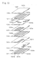
- FIG. 13 is a first exploded perspective view of the
unbalanced-balanced laminated band-pass filter according to
the fifth embodiment of the present invention;
- FIG. 14 is a second equivalent circuit diagram of the
unbalanced-balanced laminated band-pass filter according to
the fifth embodiment of the present invention;
- FIG. 15 is a third equivalent circuit diagram of the
unbalanced-balanced laminated band-pass filter according to
the fifth embodiment of the present invention;
- FIG. 16 is a block diagram showing that the
unbalanced-balanced laminated band-pass filter and a
semiconductor device can be directly connected according to
a sixth embodiment of the present invention;
- FIG . 17 is a perspective diagramwherein the semiconductor
device is mounted on the unbalanced-balanced laminated filter
according to the sixth embodiment of the present invention;
- FIG. 18 is an equivalent circuit diagram of the
conventional unbalanced laminated band-pass filter;
- FIG. 19 is an exploded perspective view of the conventional
unbalanced laminated band-pass filter;
- FIG. 20 is an exploded perspective view wherein a loading
capacity is used in a conventional laminated structure of the
unbalanced laminated band-pass filter;
- FIG. 21 is an exploded perspective view wherein SIR is
used in the conventional laminated structure of the unbalanced
laminated band-pass filter;
- FIG . 22 is an equivalent circuit diagram of a conventional
laminated balun;
- FIG. 23 is an exploded perspective view of the conventional
laminated balun;
- FIG. 24 is a block diagram of the conventional
unbalanced-balanced filter;
- FIG. 25 (a) is a diagram showing change in the frequency
of the attenuation pole of the unbalanced-balanced laminated
band-pass filter according to the second embodiment of the
present invention;
- FIG. 25 (b) is a diagram showing the change in the frequency
of the attenuation pole of the unbalanced-balanced laminated
band-pass filter according to the second embodiment of the
present invention;
- FIG. 26 shows a block diagram of a radio communication
device according to a seventh embodiment of the present
invention;
- FIG. 27 shows a block diagram of the radio communication
device according to the seventh embodiment of the present
invention;
- FIG. 28 is a diagram showing a deformed example of the
unbalanced-balanced laminated band-pass filter according to
the first embodiment of the present invention;
- FIG. 29 is a diagram showing a characteristic of the
unbalanced-balanced laminated band-pass filter of the present
invention shown in FIG. 28;
- FIG. 30 is an exploded perspective view of the
unbalanced-balanced laminated band-pass filter according to
the sixth embodiment of the present invention; and
- FIG. 31 is an exploded perspective view of the
unbalanced-balanced laminated band-pass filter according to
the sixth embodiment of the present invention.
-
Description of Symbols
-
- 101a, 101b 1/2 wavelength stripline resonators
- 102, 103a, 103b Input-output coupling capacitances
- 104a, 104b Inter-section coupling capacitances
- 105 Unbalanced terminal
- 106a, 106b Balanced terminals
- 201a, 201b 1/2 wavelength stripline electrodes
- 202, 203a, 203b Input-output stripline electrodes
- 204a, 204b Inter-section stripline electrodes
- 205, 206a, 206b, 207a, 207b External conductor electrodes
- 208a, 208b Shield conductors
- 211, 212, 213, 214, 215 Dielectric layers
- 401a, 401b, 401c 1/2 wavelength stripline resonators
- 402, 403a, 403b Input-output coupling capacitances
- 404a, 404b, 404c, 404d Inter-section coupling capacitances
- 405 Unbalanced terminal
- 406a, 406b Balanced terminals
- 500 Centerline of a 1/2 wavelength stripline resonator
- 511a, 511b 1/2 wavelength stripline resonators
- 514a, 514b Inter-section coupling capacitance electrodes
- 701a, 701b, 701c, 701d 1/4 wavelength stripline electrodes
- 702, 703a, 703b Input-output stripline electrodes
- 704a, 704b Inter-section stripline electrodes
- 705, 706a, 706b, 707a, 707b, 707c External conductors
- 708a, 708b, 708c Shield conductors
- 711, 712, 713, 714, 715, 716, 717, 718 Dielectric layers
- 801a 1/2 wavelength stripline resonator
- 821a, 821b 1/4 wavelength stripline resonators
- 802, 803a, 803b Input-output coupling capacitances
- 804a, 804b Inter-section coupling capacitances
- 805 Unbalanced terminal
- 806a, 806b Balanced terminals
- 901a 1/2 wavelength stripline electrode
- 921a, 921b 1/4 wavelength stripline electrodes
- 902, 903a, 903b Input-output stripline electrodes
- 904a, 904b Inter-section stripline electrodes
- 905, 906a, 906b, 907a, 907b External conductor electrodes
- 908a, 908b, 908c Shield conductors
- 909a, 909b Internal via conductors
- 911, 912, 913, 914, 915 Dielectric layers
- 1001a 1/2 wavelength stripline resonator
- 1021a, 1021b 1/4 wavelength stripline resonators
- 1002, 1003a, 1003b Input-output coupling capacitances
- 1004a, 1004b Inter-section coupling capacitances
- 1005 Unbalanced terminal
- 1006a, 1006b Balanced terminals
- 1101a 1/2 wavelength stripline resonator
- 1121a, 1121b 1/4 wavelength stripline resonators
- 1102, 1103a, 1103b Input-output coupling capacitances
- 1104a, 1104b Inter-section coupling capacitances
- 1105 Unbalanced terminal
- 1106a, 1106b Balanced terminals
- 1201b 1/2 wavelength stripline resonator
- 1231a 1/4 wavelength stripline resonator
- 1202, 1203a, 1203b Input-output coupling capacitances
- 1204a Inter-section coupling capacitance
- 1205 Unbalanced terminal
- 1206a, 1206b Balanced terminals
- 1301a, 1301b, 1331a 1/4 wavelength stripline electrodes
- 1302, 1303a, 1303b Input-output stripline electrodes
- 1304a Inter-section stripline electrode
- 1305, 1306a, 1306b, 1307a, 1307b, 1307c External conductor
electrodes
- 1308a, 1308b, 1308c Shield conductors
- 1311, 1312, 1313, 1314, 1315, 1316, 1317, 1318 Dielectric
layers
- 1401b 1/2 wavelength stripline resonator
- 1431a, 1431b 1/4 wavelength stripline resonators
- 1402, 1403a, 1403b Input-output coupling capacitances
- 1404a, 1404b Inter-section coupling capacitances
- 1405 Unbalanced terminal
- 1406a, 1406b Balanced terminals
- 1501b, 1501c 1/2 wavelength stripline resonators
- 1531a 1/4 wavelength stripline resonator
- 1502, 1503a, 1503b Input-output coupling capacitances
- 1504a, 1504b, 1504c Inter-section coupling capacitances
- 1505 Unbalanced terminal
- 1506a, 1506b Balanced terminals
- 160 Unbalanced-balanced band-pass filter
- 161 Semiconductor device
- 171 Unbalanced-balanced band-pass filter
- 172 Semiconductor device
- 181a, 181b 1/4 wavelength stripline resonators
- 182a, 182b Input-output coupling capacitances
- 183 Inter-section coupling capacitance
- 184a, 184b Unbalanced terminals
- 191a, 191b 1/4 wavelength stripline resonators
- 192a, 192b Input-output electrodes
- 193 Inter-section coupling electrodes
- 195a, 195b Shield conductors
- 1901, 1902, 1903, 1904, 1905, 1906 Dielectric layers
- 200a, 200b Loading capacity electrodes
- 217a, 217b, 218a, 218b Strip line resonators
- 2201 1/2 wavelength stripline resonator
- 2202a, 2202b 1/4 wavelength stripline resonators
- 2203 Unbalanced terminal
- 2204a, 2204b Balanced terminals
- 2301a 1/2 wavelength stripline electrode
- 2302a, 2302b 1/4 wavelength stripline electrodes
- 2303, 2304a, 2304b Input-output electrodes
- 2308a, 2308b Shield conductors
- 2309a, 2309b Internal via conductors
- 2311, 2312, 2313, 2314, 2315 Dielectric layers
- 241 Unbalanced filter
- 242 Balanced-unbalanced converter (balun)
- 261, 262, 271, 272 Unbalanced-balanced band-pass filter
- 263, 273 Antennas
- 264, 274 Switches
- 265, 275 Transmitting amplifier
- 266, 276 Receiving amplifier
- 267, 277 RF-IC (Radio Frequency Integrated Circuit)
semiconductor IC portion
- 268, 278 Baseband portions
-
PREFERRED EMBODIMENTS OF THE INVENTION
-
Hereafter, embodiments of the present invention will be
described by referring to the drawings.
(First Embodiment)
-
FIG . 1 is one of equivalent circuit diagrams of a band-pass
filter of an unbalanced input (output) -balanced output (input)
type according to a first embodiment of the present invention.
-
According to this configuration, stripline resonators
101a and 101b are placed, and they are electromagnetically
coupled. The stripline resonators 101a and 101b
substantially have the length of 1/2 wavelength (electrical
length, same hereafter) of desired resonant frequencies. One
end of the stripline resonator 101a is connected to an
unbalanced input (output) terminal 105 via a coupling
capacitance 102 , and both ends of the stripline resonator 101b
are connected to balanced output (input) terminals 106a and
106b via coupling capacitances 103a and 103b. Furthermore,
two inter-section coupling capacitances 104a and 104b are
connected between both ends of the stripline resonators 101a
and 101b.
-
Next, an operation of the band-pass filter shown in FIG.
1 will be described. The signal inputted from the unbalanced
terminal 105 is conveyed to the stripline resonator 101a via
the coupling capacitance 102. The stripline resonator 101a
operates as an open circuit end 1/2 wavelength resonator, and
the signal is conveyed to the second stripline resonator 101b
via the inter-section coupling capacitances 104a and 104b and
by electromagnetic coupling. In this case, as the two
inter-section coupling capacitances 104a and 104b are placed
around both ends of the stripline resonator 101a, outputs from
the stripline resonator 101a become reversed-phase signals
so as to be conveyed to the stripline resonator 101b. As the
reversed-phase signals are inputted to both ends of the
stripline resonator 101b, a middle point of the 1/2 wavelength
stripline resonator 101b is virtually grounded, substantially
operating as two 1/4 wavelength short circuit end resonators.
Furthermore, the signals conveyed to the stripline resonator
101b are conveyed as balanced signals to the balanced terminals
106a and 106b via the coupling capacitances 103a and 103b.
Furthermore, the band-pass filter forms an attenuation pole
as its pass characteristic because the stripline resonators
101a and 101b are connected by the inter-section coupling
capacitances 104a and 104b.
-
As described above, the band-pass filter according to
this embodiment plays a role of the balun for converting an
unbalanced signal to abalanced signal bymeans of the stripline
resonators 101a and 101b, and is further able to constitute
the filter having the attenuation pole with the stripline
resonators 101a, 101b and inter-section coupling capacitances
104a, 104b.
-
FIG. 2 is an exploded perspective view of a laminated
structure of the band-pass filter of the unbalanced input
(output)-balanced output (input) type for implementing the
configuration of the equivalent circuit in FIG. 1. The
laminated structure in FIG. 2 is constituted by using first
to fifth dielectric layers 211, 212, 213, 214 and 215, first
and second shield conductors 208a and 208b, stripline
electrodes 201a and 201b, input- output stripline electrodes
202, 203a and 203b, inter-section stripline electrodes 204a
and 204b, first to fifth external conductor electrodes 205,
206a, 206b, 207a and 207b. Each dielectric layer is comprised
of a crystal of Bi-Ca-Nb-O system of relative permittivity
εr = 58.
-
The first shield conductor 208a is placed on a top surface
of the first dielectric layer 211, and the second dielectric
layer 212 is laminated on the first shield conductor 208a.
The input- output stripline electrodes 202, 203a and 203b,
inter-section stripline electrodes 204a and 204b are placed
on the top surface of the second dielectric layer 212, and
the third dielectric layer 213 is laminated thereon. The 1/2
wavelength stripline electrodes 201a and 201b are placed on
the top surface of the third dielectric layer 213, and the
fourth dielectric layer 214 is laminated thereon. The second
shield conductor 208b is placed on the top surface of the fourth
dielectric layer 214, and the fifth dielectric layer 215 is
laminated thereon. The first to fifth external conductor
electrodes 205, 206a, 206b, 207a and 207b are formed on four
sides of each dielectric layer. These external conductor
electrodes connect the electrodes connected to the dielectric
layers. For instance, the first shield conductor 208a and
the second shield conductor 208b are electrically connected
via the external conductor electrodes 207a.
-
Next, a description will be given as to the operation
of the band-pass filter according to the first embodiment of
the present invention shown in FIG. 2. The 1/2 wavelength
stripline electrodes 201a and 201b in FIG. 2 are
electromagnetically coupled via the third dielectric layer
213, and operate as the 1/2 wavelength stripline resonators
101a and 101b in FIG. 1 respectively. One end of the
input-output stripline electrode 202 forms the unbalanced
input (output) terminal 105 by connecting to the first external
conductor electrode 205. The other end of the input-output
stripline electrode 202 forms parallel plate capacitors
sandwiching the third dielectric layer 213 together with an
opposed portion (corresponding to one end of the first
stripline resonator of the present invention) to the 1/2
wavelength stripline electrode 201a so as to form the coupling
capacitance 102. Ends of the input- output stripline
electrodes 203a and 203b form the balanced output (input)
terminals 106a and 106b by connecting to the second and third
external conductor electrode 206a and 206b. The other ends
of the input- output stripline electrodes 203a and 203b form
the parallel plate capacitors sandwiching the third dielectric
layer 213 together with the opposed portion (corresponding
to both ends of the second stripline resonator of the present
invention) to the 1/2 wavelength stripline electrode 201b so
as to form the coupling capacitances 103a and 103b. The
inter-section stripline electrodes 204a and 204b form the
parallel plate capacitors together with the respective opposed
portions to the 1/2 wavelength stripline electrodes 201a and
201b so as to form the inter-section coupling capacitances
104a and 104b between the resonators. Thus, the laminated
structure in FIG. 2 is the configuration for implementing the
equivalent circuit in FIG. 1.
-
FIG. 3 (a) shows a transmission characteristic of an
unbalanced input-balanced output band-pass filter of the
equivalent circuit in FIG. 1 . FIG. 3 (b) and (c) show balance
characteristics in that pass band. The balance
characteristic represents an amplitude difference and a phase
differenceofabalancedoutputsignal. InFIG. 3 (a) , however,
the horizontal axis indicates a frequency (MHz) and the
vertical axis indicates an amplitude (dB) by which the signals
outputted from the balanced terminal are synthesized. In FIG.
3 (b) , the horizontal axis indicates the frequency (MHz) and
the vertical axis indicates an amplitude difference (dB) of
the signals outputted from the balanced terminal in the pass
band. In FIG. 3 (c), the horizontal axis indicates the
frequency (MHz) and the vertical axis indicates a phase
difference (degrees) of the signals outputtedfromthebalanced
terminal in the pass band. The transmission characteristic
of an unbalanced input-balanced output band-pass filter in
the equivalent circuit in FIG. 1 is the characteristic for
generating the attenuation pole on a low-pass side of a desired
band according to FIG. 3 (a) , and is the characteristic close
to an ideal balance characteristic (amplitude difference of
0 dB, phase difference of ±180 degrees) according to FIG. 3
(b) .
-
If an input signal is added from the unbalanced terminal
105, the signals substantially of the amplitude difference
0 dB and phase difference 180 degrees are outputted from the
balanced'terminals 106a and 106b in a desired band. If the
reversed-phase signals substantially of the amplitude
difference 0 dB are added to the balanced terminals 106a and
106b, a synthetic signal thereof is outputted from the
unbalanced terminal 105. As the transmission characteristic
thereof has the attenuation pole, the filter of the present
invention can sufficiently prevent noise outside the desired
band. It can implement further miniaturization compared to
the configuration in the past.
-
As for the characteristic of the equivalent circuit in
FIG. 1, the number of components is smaller than the
configuration for externally connecting an unbalanced
laminated band-pass filter to a laminated balun in the past
so that the loss in the pass band is improved by 50 percent
or so.
-
The first embodiment of the present invention was
described as having two stripline resonators, there may be
three or more. For instance, as shown in FIG. 4, it may be
the configuration wherein three 1/2 wavelength stripline
resonators 401a, 401b and 401c are coupled by inter-section
coupling capacitances 404a, 404b, 404c and 404d respectively.
The operation of this circuit is the same as that of the
equivalent circuit in FIG. 1 so that the unbalanced-balanced
band-pass filter also having the attenuation pole is
constituted.
-
The first embodiment of the present invention can be
further miniaturized by rendering the resonators shorter by
means of a loading capacity and SIR.
-
The configuration described above has the characteristic
close to an ideal balance characteristic, and the transmission
characteristic thereof has a band-pass filter characteristic
having the attenuation pole. In the case of the laminated
structure as described, the number of components is
significantly smaller than the configuration in the past.
Therefore, it is possible to realize the miniaturization as
the configuration of the unbalanced-balanced laminated filter
and significantly improve the loss in the pass band as to the
transmission characteristic.
(Second Embodiment)
-
Next, FIG. 5 (a) shows an equivalent circuit configuration
of the band-pass filter of the unbalanced input
(output)-balanced output (input) type for controlling the
frequency of the attenuation pole according to the second
embodiment of the present invention.
-
As shown in FIG. 5 (a) , this is the configuration wherein,
as to the equivalent circuit configuration of the
unbalanced-balanced laminated filter in FIG. 1, the
inter-section coupling capacitance 104a as an example of a
first capacity element of the present invention and the
inter-section coupling capacitance 104b as an example of a
second capacity element are placed at distances L1 and L2 in
a central direction from both ends of the pair of stripline
resonators 101a and 101b of substantial 1/2 wavelength of the
resonant frequencies respectively. It is possible to realize
the laminated structure for implementing this equivalent
circuit by changing coupling positions of the inter-section
coupling capacitances in FIG. 2 of the first embodiment. A
concrete positional relationship thereof is shown in FIG. 5
(b) . Here, the above L1 and L2 are defined as the distances
between both ends of each of stripline resonators 511a and
511b and centers of the widths of inter-section coupling
capacitance electrodes 514a and 514b. Accordingly, it is
possible to change the distances L1 and L2 by 0.5W or more
which is a half of a width W of the inter-section coupling
capacitance electrode. To be more specific, in the case where
the inter-section coupling capacitance electrodes 514a and
514b are placed at both ends of the stripline resonators 511a
and 511b, it is L1 = 1/2W and L2 = 1/2W so that L1 and L2 are
the minimum values.
-
FIGS. 6 (a) to (c) show the characteristics in the case
of changing the positions of one or two inter-section coupling
capacitances in the above range. FIGS. 6 (a) to (c) show the
change in the transmission characteristic and the balance
characteristic in the pass band in the case of moving the
inter-section coupling capacitance electrode 514a on the side
to which the unbalanced terminal 105 is connected of the two
inter-section coupling capacitances, that is, in the case of
changing L1. FIG. 25 (a) shows the change in the transmission
characteristic in the case of moving the other inter-section
coupling capacitance electrode 514b, that is, in the case of
changing L2. FIG. 25 (b) shows the change in the transmission
characteristic in the case of moving each of the two
inter-section coupling capacitance electrodes 514a and 514b
by the same distance from both ends of the stripline resonator,
that is, in the case of changing L1 and L2 to the same extent.
As for the horizontal axes, FIGS. 6 (a) and FIGS. 25 (a) and
(b) indicate the frequencies, and FIGS. 6 (b) and (c) indicate
the position (L1) of the inter-section coupling capacitance
electrode. As for the vertical axes, FIGS. 6 (a) and FIGS.
25 (a) and (b) indicate the amplitude (dB) having the signals
outputted from the balanced terminals mutually synthesized,
FIGS. 6 (b) indicates the maximum amplitude difference (dB)
in the band of the signals outputted from the balanced terminals,
and FIGS. 6 (c) indicates the maximum phase difference in the
band. Consequently, it can be seen from FIGS. 6 (a) and FIGS.
25 (a) and (b) that the frequency of the attenuation pole is
changed to the higher side by moving either position of the
two inter-section coupling capacitances toward the center of
the 1/2 wavelength stripline resonators 511a and 511b. As
shown in FIGS . 6 (b) and (c) , as for the balance characteristic,
it is desirable to change L1 in the range of 0.2λ (λ is a
wavelength at the resonant frequency) or less because, in the
case of changing only L1, the maximum amplitude difference
and maximum phase difference are abruptly deteriorated at 0 . 2λ
(wavelength) or more.
-
Next, FIG. 7 is an exploded perspective view of the
laminated structure for implementing the equivalent circuit
configuration for controlling the frequency of the attenuation
pole in FIG. 5 (a). The configuration and operation of the
filter according to this embodiment will be described by
referring to FIG. 7. The laminated structure in FIG. 7 is
constituted by using first to eighth dielectric layers 711,
712, 713, 714, 715, 716, 717 and 718, first to third shield
conductors 708a, 708b and 708c, stripline electrodes 701a,
701b, 701c, 701d, 702, 703a, 703b, 704a and 704b, and first
to sixth external conductors 705, 706a, 706b, 707a, 707b and
707c.
-
The shield conductor 708a is placed on a top surface of
the first dielectric layer 711, and the second dielectric layer
712 is laminated on the shield conductor 708a, and the stripline
electrodes 702, 703b and 704b are placed on the top surface
thereof. The third dielectric layer 713 is further laminated
thereon, the stripline electrodes 701c and 701d are placed
on the top surface thereof, the fourth dielectric layer 714
is laminated thereon, the shield conductor 708b is placed on
the top surface thereof, the fifth dielectric layer 715 is
laminated thereon, and the stripline electrodes 701a and 701b
are placed on the top surface thereof. Furthermore, the sixth
dielectric layer 716 is laminated thereon, the stripline
electrodes 703a and 704a are placed on the top surface thereof,
the seventh dielectric layer 717 is laminated thereon, the
shield conductor 708c is placed on the top surface thereof,
and the eighth dielectric layer 718 is laminated thereon. The
external conductors 705, 706a, 706b, 707a, 707b and 707c are
formed on the four sides of the layered product thus laminated.
-
The stripline electrodes 701a and 701b in FIG. 7 are
electromagnetically coupled via the fifth dielectric layer
715, and the stripline electrodes 701c and 701d are
electromagnetically coupled via the third dielectric layer
713. Here, the stripline electrodes 701a, 701b, 701c and 701d
are substantially constituted as the stripline resonators of
1/4 wavelength of desired resonant frequencies. The
stripline electrodes 701a and 701c, and the stripline
electrodes 701b and 701d are having the shield conductor 708b
in between them respectively. The stripline electrodes 701a
and 701c are connected by the external conductor 707a, and
the stripline electrodes 701b and 701d are connected by the
external conductor 707b . Thus, the stripline electrodes 701a
and 701c combinedly form the 1/2 wavelength stripline resonator
101a, and the stripline electrodes 701b and 701d combinedly
form the 1/2 wavelength stripline resonator 101b.
-
One end of the stripline electrode 702 is connected to
the external conductor 705 to form the unbalanced input
(output) terminal 105, and forms the parallel plate capacitors
sandwiching the third dielectric layer 713 together with the
opposed portion (corresponding to one end of the first
stripline resonator of the present invention) to the stripline
electrode 701c so as to form the coupling capacitances 102.
One end of the stripline electrode 703a is connected to the
external conductor 706a to form one of the balanced output
(input) terminals 106a, and forms the parallel plate capacitors
sandwiching the sixth dielectric layer 716 together with the
opposed portion (corresponding to either end of the second
stripline resonator of the present invention) to the stripline
electrode 701b so as to form the coupling capacitances 103a .
One end of the stripline electrode 703b is connected to the
external conductor 706b to form the balanced output (input)
terminal 106b, and forms the parallel plate capacitors
sandwiching the third dielectric layer 713 together with the
opposed portion (corresponding to the other end of the second
stripline resonator of the present invention) to the stripline
electrode 701d so as to form the coupling capacitances 103b.
The stripline electrode 704a is placed opposite the stripline
electrodes 701a and 701b to form the inter-section coupling
capacitance 104a between the resonators, and the stripline
electrode 704b is placed opposite the stripline electrodes
701c and 701d to form the inter-section coupling capacitance
104b between the resonators.
-
It is possible, by controlling at least one of the
positions of the stripline electrodes 704a and 704b, to control
the frequency of the attenuation pole as mentioned above. In
this case, the stripline electrodes 704a and 704b are placed
in different dielectric layers, and the shield conductor 708b
is in between them so as to have the effect of counteracting
the mutual coupling.
-
According to this configuration, the stripline
electrodes 701a and 701c, and the stripline electrode 701b
and the fourth stripline electrode 701d are connected by the
external conductors 707a and 707b respectively to form the
1/2 wavelength stripline resonators 101a and 101b. However,
theymay also be connected by using the internal via conductors.
The above configuration can realize further miniaturization
than the case of the first embodiment.
-
According to the second embodiment of the present
invention, it is possible, even if constituted by further
adding the stripline resonators of substantial 1/2 wavelength,
to realize the unbalanced-balanced band-pass filter.
-
According to the second embodiment of the present
invention, it can be further miniaturized by rendering the
stripline resonators shorter by means of the loading capacity
and SIR.
-
As described above, as with the configuration according
to the first embodiment, the configuration according to the
second embodiment of the present invention has the
characteristic close to the ideal balance characteristic, and
its transmission characteristic has the band-pass filter
characteristic having the attenuation pole. The described
laminated structure has the number of components significantly
smaller than the configuration in the past, and so it can realize
the miniaturization as the configuration of the
unbalanced-balanced laminated filter and significantly
improve the loss in the pass band as to the transmission
characteristic.
(Third Embodiment)
-
FIG. 8 is an equivalent circuit diagram of the
unbalanced-balanced band-pass filter according to a third
embodiment of the present invention.
-
According to this configuration, there are one stripline
resonator 801a of substantial 1/2 wavelength of the desired
resonant frequencies and a pair of stripline resonators 821a
and 821b of substantial 1/4 wavelength of the desired resonant
frequencies. The stripline resonators 821a and 821b are
placed in parallel with the stripline resonator 801a and
mutually in series in order to be electromagnetically coupled
respectively. One end of the stripline resonator 801a is
connected to an unbalanced input (output) terminal 805 via
a coupling capacitance 802. Ends of the respective stripline
resonators 821a and 821b are connected to balanced output
(input) terminals 806a and 806b via coupling capacitances 803a
and 803b, and the other ends of the respective stripline
resonators 821a and 821b form the short circuit ends.
Furthermore, an inter-section coupling capacitance 804a is
connected between the stripline resonators 801a and 821a, and
an inter-section coupling capacitance 804b is connected
between the stripline resonators 801a and 821b.
-
Next, the operation of the band-pass filter shown in FIG.
8 will be described. The signal inputted from the unbalanced
terminal 805 is conveyed to the stripline resonator 801a via
the coupling capacitance 802. The stripline resonator 801a
operates as the open circuit end 1/2 wavelength resonator,
and the signal is conveyed to the stripline resonators 821a
and 821b via the inter-section coupling capacitances 804a and
804b. In this case, as the inter-section coupling
capacitances 804a and 804b are placed around both ends of the
stripline resonator 801a, the outputs from the stripline
resonator 801a become the reversed-phase signals so as to be
conveyed to the stripline resonators 821a and 821b. The
stripline resonators 821a and 821b operate as the 1/4
wavelength short circuit end resonators. Furthermore, the
stripline resonators 821a and 821b convey the conveyed signals
as the balanced signals to the balanced terminals 806a and
806b via the coupling capacitances 803a and 803b. Furthermore,
the band-pass filter forms the attenuation pole as its pass
characteristic because the stripline resonators 801a and 821b
are connected by the inter-section coupling capacitance 804a
and the stripline resonators 801a and 821b are connected by
the inter-section coupling capacitance 804b.
-
As described above, the stripline resonators 801a, 821a
and 821b constitute the balun for converting the unbalanced
signal to the balanced signal, and further operate as the filter
having the attenuation pole together with inter-section
coupling capacitances 804a and 804b.
-
FIG. 9 is an exploded perspective view of the laminated
structure of the band-pass filter of the unbalanced input
(output)-balanced output (input) type for implementing the
configuration of the equivalent circuit in FIG. 8. The
laminated structure in FIG. 9 is constituted by using first
to fifth dielectric layers 911, 912 , 913, 914 and 915, first
and second shield conductors 908a and 908b, stripline
electrodes 901a, 902, 903a, 903b, 904a, 904b, 921a and 921b,
first to fifth external conductors 905, 906a, 906b, 907a and
907b, and first and second internal via conductors 909a and
909b. Each dielectric layer is comprised of the crystal of
Bi-Ca-Nb-O system of relative permittivity (εr) = 58.
-
The first shield conductor 908a is placed on the top
surface of the first dielectric layer 911, and the second
dielectric layer 912 is laminated on the first shield conductor
908a. The stripline electrodes 902, 903a, 903b, 904a and 904b
are placed on the top surface thereof, and the third dielectric
layer 913 is laminated thereon. Furthermore, the stripline
electrodes 901a, 921a and 921b are placed on the top surface
of the third dielectric layer 913, and the fourth dielectric
layer 914 is laminated thereon, the second shield conductor
908b is placed on the top surface thereof, and the fifth
dielectric layer 915 is laminated thereon. The first to fifth
external conductors 905, 906a, 906b, 907a and 907b are formed
on the four sides of the layered product thus constituted,
and the internal via conductors 909a and 909b are formed in
the fourth dielectric layer 914.
-
Next, a description will be given as to the operation
of the laminated structure in FIG. 9 according to a third
embodiment of the present invention. The stripline
electrodes 901a and 921a and the stripline electrodes 901a
and 921b in FIG. 9 are electromagnetically coupled via the
third dielectric layer 913. Ends of the stripline electrodes
921a and 921b are connected to the shield conductor 908b via
the internal via conductors 909a and 909b so as to operate
as the short circuit ends. One end of the stripline electrode
902 is connected to the external conductor 905 to form the
unbalanced input (output) terminal 805, and the other end
thereof forms the parallel plate capacitors sandwiching the
third dielectric layer 913 together with the opposed portion
to the stripline electrode 901a so as to form the coupling
capacitance 802. Ends of the stripline electrodes 903a and
903b are connected to the external conductors 906a and 906b
to form the balanced output (input) terminals 806a and 806b
respectively, and the other ends thereof form the parallel
plate capacitors sandwiching the third dielectric layer 913
together with the opposed portion to the stripline electrodes
921a and 921b so as to form the coupling capacitances 803a
and 803b. The stripline electrodes 904a and 904b form the
parallel plate capacitors together with the opposed portion
to the stripline electrodes 901a, 921a and 921b so as to form
the inter-section coupling capacitances 804a and 804b between
the resonators.
-
According to the third embodiment of the present invention,
it is possible, even if constituted by further adding the
stripline resonators of 1/2 wavelength in substance, to realize
the unbalanced-balanced band-pass filter.
-
According to the third embodiment of the present invention,
it can be further miniaturized by rendering the stripline
resonators shorter by means of the loading capacity and SIR.
-
According to the third embodiment, it is possible, by
changing the coupling positions of the two inter-section
coupling capacitances, to have the same effect of controlling
the frequency of the attenuation pole as described as to the
second embodiment.
-
As described above, as with the configurations according
to the first or second embodiment of the present invention,
the configuration according to the third embodiment has the
characteristic close to the ideal balance characteristic, and
its transmission characteristic has the band-pass filter
characteristic having the attenuation pole. The described
laminated structure has the number of components significantly
smaller than the configuration in the past, and so it can realize
the miniaturization as the configuration of the
unbalanced-balanced laminated filter and significantly
improve the loss in the pass band as to the transmission
characteristic.
(Fourth Embodiment)
-
Next, FIG. 10 is an equivalent circuit diagram of the
unbalanced-balanced band-pass filter according to a fourth
embodiment of'the present invention.
-
According to this configuration, there are one stripline
resonator 1001a of substantial 1/2 wavelength of the desired
resonant frequencies and a pair of stripline resonators 1021a
and 1021b of substantial 1/4 wavelength of the desired resonant
frequencies. The stripline resonators 1021a and 1021b are
placed in parallel with the stripline resonator 801a so as
to be electromagnetically coupled respectively. One end of
the stripline resonator 1001a is connected to an unbalanced
input (output) terminal 1005 via a coupling capacitance 1002.
Ends of the stripline resonators 1021a and 1021b are connected
to balanced output (input) terminals 1006a and 1006b via
coupling capacitances 1003a and 1003b. The stripline
resonators 1021a and 1021b are mutually connected in series.
Furthermore, an inter-section coupling capacitance 1004a is
connected between one of the open ends of the stripline
resonators 1001a and the open end of the stripline resonators
1021a, and an inter-section coupling capacitance 1004b is
connected between the other end of the open end of the stripline
resonators 1001a and that of the stripline resonators 1021b.
-
This is the configuration wherein the equivalent circuit
configuration according to the first embodiment is constituted
by two series-connected 1/4 wavelength stripline resonators
1021a and 1021b in place of the 1/2 wavelength stripline
resonators 101b. Therefore the operation in the
configuration in FIG. 10 is the same as the operation in the
equivalent circuit configuration according to the first
embodiment.
-
Furthermore, FIG. 11 is another equivalent circuit
diagram representing the unbalanced-balanced band-pass
filter according to the fourth embodiment of the present
invention.
-
According to this configuration, one 1/2 wavelength
stripline resonator 1101a and a pair of 1/4 wavelength
stripline resonators 1121a and 1121b are placed in parallel
to be electromagnetically coupled respectively. One end of
the stripline resonator 1101a is connected to an unbalanced
input (output) terminal 1105 via a coupling capacitance 1102.
Ends of the stripline resonators 1121a and 1121b are connected
to balanced output (input) terminals 1106a and 1106b via
coupling capacitances 1103a and 1103b respectively, and the
other ends of the stripline resonators 1121a and 1121b form
the short circuit ends respectively. Furthermore, an
inter-section coupling capacitance 1104a is connected between
the center of the stripline resonator 1101a and the open end
of the stripline resonator 1121a, and 1104b is connected
between the center of the stripline resonator 1101a and the
open end of the stripline resonator 1121b.
-
This configuration is equivalent to the equivalent
circuit configuration in FIG. 8 according to the third
embodiment wherein the point at which the two inter-section
coupling capacitances 804a and 804b are connected is changed
from both ends to the center of the 1/2 wavelength stripline
resonator 801a, and it performs the same operation. Therefore,
it is also possible, according to this configuration, to
constitute the filter having the attenuation pole.
-
According to the fourth embodiment of the present
invention, it is possible, even if constituted by further
adding the stripline resonators of 1/2 wavelength in substance,
to realize the unbalanced-balanced band-pass filter.
-
According to the fourth embodiment of the present
invention, it can be further miniaturized by rendering the
stripline resonators shorter by means of the loading capacity
and SIR.
-
According to the fourth embodiment, it is possible, by
changing the coupling positions of the two inter-section
coupling capacitances, to have the same effect of controlling
the frequency of the attenuation pole as described as to the
second embodiment.
-
As described above, as with the configurations according
to the first, second or third embodiment of the present
invention, the configuration according to the fourth
embodiment has the characteristic close to the ideal balance
characteristic, and its transmission characteristic has the
band-pass filter characteristic having the attenuation pole.
The laminated structure of the described configuration has
the number of components significantly smaller than the
configuration in the past, and so it can realize the
miniaturization as the configuration of the
unbalanced-balanced laminated filter and significantly
improve the loss in the pass band as to the transmission
characteristic.
(Fifth Embodiment)
-
Next, FIG. 12 is an equivalent circuit diagram of the
unbalanced-balanced band-pass filter according to a fifth
embodiment of the present invention.
-
According to this configuration, there are one stripline
resonator 1231a of substantial 1/4 wavelength of the desired
resonant frequencies and one stripline resonator 1201b of
substantial 1/2 wavelength of the desired resonant frequencies
placed in parallel to be electromagnetically coupled
respectively. One end of the stripline resonator 1231a is
connected to an unbalanced input (output) terminal 1205 via
a coupling capacitance 1202, and the other end thereof forms
the short circuit end. Both ends of the stripline resonator
1201b are connected to balanced output (input) terminals 1206a
and 1206b via coupling capacitances 1203a and 1203b
respectively. Furthermore, an inter-section coupling
capacitance 1204a is connected between the open end of the
stripline resonator 1231a and one end of the stripline
resonators 1201b.
-
Next, a description will be given as to the operation
of the band-pass filter shown in FIG. 12. The signal inputted
from the unbalanced terminal 1205 is conveyed to the stripline
resonator 1231a via the coupling capacitance 1202. The
stripline resonator 1231a operates as the short circuit end
1/4 wavelength resonator, and the signal is conveyed to the
stripline resonator 1201b via the inter-section coupling
capacitance 1204a. The stripline resonator 1201b operates
as the open circuit end 1/2 wavelength resonator, and also
operates as the filter having the attenuation pole together
with the stripline resonator 1231a and the inter-section
coupling capacitance 1204a. As the stripline resonator 1201b
is the 1/2 wavelength resonator, the signal conveyed to the
stripline resonator 1201b is outputted as the balanced signal
to the balanced terminals 1206a and 1206b.
-
This configuration can realize the unbalanced-balanced
band-pass filter.
-
According to the configuration in FIG. 12, it is possible
to realize the same unbalanced-balanced band-pass filter by
constituting one 1/4 wavelength stripline resonator with two
1/4 wavelength stripline resonators via the inter-section
coupling capacitance.
-
FIG. 13 is an exploded perspective view of the laminated
structure for implementing the equivalent circuit
configuration in FIG. 12. The laminated structure in FIG.
13 is constituted by using first to eighth dielectric layers
1311, 1312, 1313, 1314, 1315, 1316, 1317 and 1318, first to
third shield conductors 1308a, 1308b and 1308c, stripline
electrodes 1331a, 1301a, 1301b, 1302, 1303a, 1303b and 1304a,
firstto sixth external conductor electrodes 1305, 1306a, 1306b,
1307a, 1307b and 1307c.
-
The shield conductor 1308a is placed on the top surface
of the first dielectric layer 1311, and the second dielectric
layer 1312 is laminated thereon, the stripline electrode 1303b
is placed on the top surface thereof. Furthermore, the third
dielectric layer 1313 is laminated thereon, the stripline
electrodes 1301b is placed on the top surface thereof, the
fourth dielectric layer 1314 is laminated thereon, the shield
conductor 1308b is placed on the top surface thereof, the fifth
dielectric layer 1315 is laminated thereon, and the stripline
electrodes 1331a and 1301a are placed on the top surface thereof.
Furthermore, the sixth dielectric layer 1316 is laminated
thereon, the stripline electrodes 1302, 1303a and 1304a are
placed on the top surface thereof, the seventh dielectric layer
1317 is laminated thereon, the shield conductor 1308c is placed
on the top surface thereof, and the eighth dielectric layer
1318 is laminated thereon. The external conductors 1305,
1306a, 1306b, 1307a, 1307b and 1307c are formed on the four
sides of the layered product thus constituted.
-
Next, a description will be given as to the operation
of the laminated structure in FIG. 13 according to a fifth
embodiment. The stripline electrodes 1331a and 1301a in FIG.
13 are electromagnetically coupled via the fifth dielectric
layer 1315. Here, the stripline electrodes 1331a, 1301a and
1301b are constituted as the 1/4 wavelength stripline
resonators respectively. The stripline electrodes 1301a and
1301b are connected to the external conductor 1307b by
sandwiching the shield conductor 1308b so as to combinedly
form a 1/2 wavelength stripline resonator 1201b. One end of
the stripline electrode 1302 is connected to the external
conductor 1305 to form an unbalanced terminal 1205, and the
other end thereof forms the parallel plate capacitors
sandwiching the sixth dielectric layer 1316 together with the
opposed portion to the stripline electrode 1331a so as to form
the coupling capacitance 1202. One end of the stripline
electrode 1303a is connected to the external conductor 1306a
to form one of the balanced terminals 1206a, and the other
end thereof forms the parallel plate capacitors sandwiching
the sixth dielectric layer 1316 together with the opposed
portion to the stripline electrode 1301a so as to form the
coupling capacitance 1203a. One end of the stripline
electrode 1303b is connected to the external conductor 1306b
to form the other balanced terminal 1206b, and the other end
thereof forms the parallel plate capacitors sandwiching the
third dielectric layer 1313 together with the opposed portion
to the stripline electrode 1301b so as to form the coupling
capacitance 1203b. The stripline electrode 1304a forms the
parallel plate capacitors together with the opposed portions
to the stripline electrodes 1331a and 1301a so as to form the
inter-section coupling capacitance 1204a between the
resonators.
-
According to this configuration, the stripline
electrodes 1301a and 1301b are connected by the external
conductor 1307b so as to form a 1/2 wavelength stripline
resonator 1201b. It is also possible to connect the stripline
electrodes 1301a and 1301b by using the internal via conductor.
The mutual coupling is counteracted by having the shield
conductor 1308b between the stripline electrodes 1301a and
1301b. It is possible to implement further miniaturization
by this configuration.
-
It can be further miniaturized by rendering the stripline
resonators shorter by means of the loading capacitor and SIR.
-
FIG. 14 is an equivalent circuit diagram comprised of
two 1/4 wavelength stripline resonators 1431a, 1431b and one
1/2 wavelength stripline resonator 1401b.
-
According to this configuration, there are two 1/4
wavelength stripline resonators 1431a, 1431b and one 1/2
wavelength stripline resonator 1401b placed in parallel to
be electromagnetically coupled respectively. One end of the
stripline resonator 1431a is connected to an unbalanced input
(output) terminal 1405 via a coupling capacitance 1402, and
the other end thereof forms the short cuircuit top end. Both
ends of the stripline resonator 1401b are connected to balanced
output (input) terminals 1406a and 1406b via coupling
capacitances 1403a and 1403b respectively. Furthermore,
inter-section coupling capacitances 1404a and 1404b are
connected between the open ends of the stripline resonator
1431a and 1431b and between the open end of the stripline
resonator 1431b and one end of the stripline resonator 1401b,
and the other end of the stripline resonator 1431b forms the
short circuit end.
-
Next, a description will be given as to the operation
of the band-pass filter shown in FIG. 14. The signal inputted
from the unbalanced terminal 1405 is conveyed to the stripline
resonator 1431a via the coupling capacitance 1402. The
stripline resonator 1431a operates as the short circuit end
1/4 wavelength resonator, and the signal is conveyed to the
stripline resonator 1431b via the first inter-section coupling
capacitance 1404a. The stripline resonator 1431b also
operates as the short circuit end 1/4 wavelength resonator,
and the signal is conveyed to the stripline resonator 1401b
via the second inter-section coupling capacitance 1404b . The
stripline resonator 1431a forms the filter having the
attenuation pole together with the stripline resonator 1431b
and its inter-section coupling capacitance 1404a. As the
stripline resonator 1401b is the 1/2 wavelength resonator,
the signal is outputted as the balanced signal to the balanced
terminal. This configuration can realize the
unbalanced-balanced band-pass filter. It is also possible
to realize the same operation by further adding the 1/4
wavelength stripline resonator or 1/2 wavelength stripline
resonator via the inter-section coupling capacitance.
-
According to the configuration in FIG. 14, it is possible
to realize the same unbalanced-balanced band-pass filter by
constituting one 1/2 wavelength stripline resonator with two
1/4 wavelength stripline resonators via a pair of inter-section
coupling capacitances.
-
FIG. 15 is an equivalent circuit diagram comprised of
the two 1/2 wavelength stripline resonators and one 1/4
wavelength stripline resonator.
-
According to this configuration, there are one 1/4
wavelength stripline resonator 1531a and two 1/2 wavelength
stripline resonators 1501b and 1501c placed in parallel to
be electromagnetically coupled respectively. One end of the
stripline resonator 1531a is connected to an unbalanced input
(output) terminal 1505 via a coupling capacitance 1502, and
the other end thereof forms the short circuit end. Both ends
of the stripline resonator 1501b are connected to balanced
output (input) terminals 1506a and 1506b via coupling
capacitances 1503a and 1503b respectively. Furthermore,
inter-section coupling capacitances 1504a, 1504b and 1504c
are connected between the open end of the stripline resonator
1531a and one end of the stripline resonator 1501c and between
both ends of the stripline resonator 1501c and both ends of
the stripline resonator 1501b respectively.
-
Next, the operation of the band-pass filter shown in FIG.
15 will be described. The signal inputted from the unbalanced
terminal 1505 is conveyed to the stripline resonator 1531a
via the coupling capacitance 1502. The stripline resonator
1531a operates as the short circuit end 1/4 wavelength
resonator, and the signal is conveyed to the stripline
resonator 1501c via the first inter-section coupling
capacitance 1504a. The stripline resonator 1501c operates
as the open circuit end 1/2 wavelength resonator, and the signal
is conveyed to the stripline resonator 1501b via the second
inter-section coupling capacitances 1504b and 1504c. The
stripline resonator 1531a forms the filter having the
attenuation pole together with the 1501c and its inter-section
coupling capacitance 1504a. As the stripline resonator 1501b
is the 1/2 wavelength resonator, the signal conveyed to the
stripline resonator 1501b is outputted as the balanced signal
to the balanced terminals 1506a and 1506b.
-
This configuration can realize the unbalanced-balanced
band-pass filter. Here, it is also possible to have the same
effects by further placing the 1/2 wavelength stripline
resonator via the inter-section coupling capacitance in
addition.
-
It is possible to constitute any 1/2 wavelength stripline
resonator in the configuration of the fifth embodiment with
two 1/4 wavelength stripline resonators.
-
As described above, as with the configurations according
to the first to fourth embodiments of the present invention,
the configuration according to the fifth embodiment has the
characteristic close to the ideal balance characteristic, and
its transmission characteristic has the band-pass filter
characteristic having the attenuation pole. The laminated
structure of the described configuration can have the number
of components significantly smaller than the configuration
in the past, and so it can realize the miniaturization as the
configuration of the unbalanced-balanced laminated filter and
significantly improve the loss in the pass band as to the
transmission characteristic.
(Sixth Embodiment)
-
FIG. 30 shows the laminated structure of the band-pass
filter according to the sixth embodiment of the present
invention. The configuration of the band-pass filter shown
in FIG. 30 is a reversal of vertical placement of the dielectric
layers 213 and 212 in the laminated structure of the band-pass
filter shown in FIG. 2. The first shield conductor 208a and
second shield conductor 208b are connected by the external
conductor electrodes 207a and 207b. According to this
embodiment, however, the external conductor electrodes 207a
and 207b have a width to be inductive and connect the first
shield conductor 208a and second shield conductor 208b around
the frequency to be used. To be more specific, the second
shield conductor 208b is in a state of floating from the first
shield conductor 208a by the amount of induction of the external
conductor electrodes 207a and 207b. In this case, the second
shield conductor 208b is sufficiently longer than the length
of the stripline electrodes 201a and 201b (λ/2: λ is the
wavelength of the resonant frequency).
-
According to this configuration, the second shield
conductor 208b operates as a both top ends short circuit
resonator. A resonant frequency f' in this case is different
from a resonant frequency f of the stripline electrodes 201a
and 201b in the layer. The input- output stripline electrodes
202 , 203a and 203b are placed below the second shield conductor
208b, and so parasitic capacitances are generated between the
second shield conductor 208b and the input- output stripline
electrodes 202, 203a and 203b respectively. Thus, the signal
inputted from the input- output stripline electrodes 202 , 203a
or 203b around the resonant frequency of the second shield
conductor 208b is propagated to the second shield conductor
208b via each parasitic capacitance. Therefore, the shield
conductor 208b operates to form a new attenuation pole in the
amplitude characteristic together with each parasitic
capacitance.
-
According to this embodiment, it was described that the
length of the second shield conductor 208b is sufficiently
longer than the length of the stripline electrodes 201a and
201b (λ/2 ) . In the case where such a condition is not satisfied,
however, the attenuation pole is generated in the band of the
unbalanced-balanced filter. To avoid such an attenuation
pole in the band, it is necessary to increase the short circuit
portions between the first shield conductor 208a and second
shield conductor 208b. To be more specific, the width should
be formed in the frequency to be used so that the external
conductor electrodes 207a and 207b do not have an inductive
component. For that purpose, for instance, there is a
thinkable configuration wherein the first shield conductor
208a and second shield conductor 208b are connected via four
conductors as shown in FIG. 31.
(Seventh Embodiment)
-
Here, FIG. 16 shows the configuration wherein the
unbalanced-balanced filter according to the first to sixth
embodiments and a semiconductor devicefor performing balanced
operation are directly connected. This operation will be
described next.
-
A semiconductor device 161 often connects a capacitor
for interrupting a direct current to the inside or the outside.
Here, all the configurations according to the first to sixth
embodiments of the present invention are characterizedby being
connected to the balanced terminal via the coupling capacitance.
Therefore, it is possible to directly connect an
unbalanced-balanced band-pass filter 160 of the first to sixth
embodiments to the semiconductor device 161 via no new
capacitor for interrupting the direct current. For that
purpose, the function of interrupting the direct current should
be provided to at least one of the coupling capacitances
corresponding to matching elements of the present invention
by which each input terminal is connected to each stripline
resonator and each output terminal is connected to each
stripline resonator.
-
As shown in FIG . 17 , it is possible to mount a semiconductor
device 172 on an unbalanced-balanced laminated filter 171
according to the first to sixth embodiments. It is possible
to mount the matching circuit of the semiconductor device 172
on or inside the laminated filter 171.
-
As described above, the configuration according to the
seventh embodiment can connect the unbalanced-balanced
laminated filter to the semiconductor device via no new
capacitorforinterrupting the direct current,andso reduction
in the number of components can be expected.
(Eighth Embodiment)
-
FIG. 26 shows a block diagram of a radio communication
device using the unbalanced-balanced filter according to the
first to sixth embodiments. Next, the operation of this
configuration will be described.
-
In FIG. 26, a transmitting signal is modulated from a
digital signal to an analog signal in a baseband portion 268,
and the modulated analog signal is processed in a semiconductor
IC portion 267 , where the transmitting signal having performed
the balanced operation is filtered by an unbalanced-balanced
laminated filter 261 according to the first to sixth
embodiments and conveyed to a transmitting amplifier 265. The
transmitting signal amplified to a desired power level by the
transmitting amplifier 265 is transmitted by being conveyed
to a switch 264 and an antenna 263. The receiving signal
received by the antenna 2 63 is conveyed to a receiving amplifier
266 by the switch 264, where the amplified signal is conveyed
to an unbalanced-balanced laminated filter 262 according to
the first to sixth embodiments so as to be filtered. The
outputted receiving signal is processed in the semiconductor
IC portion 267 and is conveyed to the baseband portion 268
so as to be signal-processed and demodulated into the digital
signal.
-
As described above, it is possible to implement the radio
communication device by using the unbalanced-balanced
laminated filter according to the first to sixth embodiments.
-
Here, as shown in FIG. 27, it is also possible to implement
the same radio communication device by replacing the receiving
amplifier 266 and unbalanced-balanced laminated filter 262
with the receiving amplifier 266 for processing the receiving
signal and an unbalanced-balanced laminated filter 272
according to the first to sixth embodiments.
-
It is also possible to constitute as a module at least
one of the unbalanced-balanced laminated filter 262 according
to the first to sixth embodiments, transmitting amplifier 265,
receiving amplifier 266 and semiconductor IC portion 267.
-
In the case where the unbalanced-balanced filter is
required in a high-frequency circuit portion other than the
radio communication device of the above described
configuration, it is possible to implement it by using the
unbalanced-balanced laminated filter according to the first
to sixth embodiments or a modular configuration including it.
-
In the above description, an impedance element of the
present invention is corresponding to the inter-section
coupling capacitances 104a and 104b in the example shown in
FIGS. 1 and 5, to the inter-section coupling capacitances 404a,
404b, 404c and 404d in the example shown in FIG. 4, to the
inter-section coupling capacitances 804a and 804b in the
example shown in FIG. 8, to the inter-section coupling
capacitances 1004a and 1004b in the example shown in FIG. 10,
to the inter-section coupling capacitances 1104a and 1104b
in the example shown in FIG. 11, to the inter-section coupling
capacitance 1204a in the example shown in FIG. 12, to the
inter-section coupling capacitances 1404a and 1404b in the
example shown in FIG. 14, and to the inter-section coupling
capacitances 1504a, 1504b and 1504c in the example shown in
FIG. 15.
-
In the above description, the first capacity element
according to the present invention is corresponding to the
inter-section coupling capacitance 104a in the examples shown
in FIGS. 1 and 5, to the inter-section coupling capacitance
404a in the example shown in FIG. 4, to the inter-section
coupling capacitance 804a in the example shown in FIG. 8, to
the inter-section coupling capacitance 1004a in the example
shown in FIG. 10.
-
The second capacity element according to the present
invention is corresponding to the inter-section coupling
capacitance 104b in the example shown in FIGS. 1 and 5, to
the inter-section coupling capacitance 404b in the example
shown in FIG. 4, to the inter-section coupling capacitance
804b in the example shown in FIG. 8, to the inter-section
coupling capacitance 1004b in the example shown in FIG. 10.
-
The third capacity element according to the present
invention is corresponding to the inter-section coupling
capacitance 404c in the example shown in FIG. 4, to the
inter-section coupling capacitance 1504b in the example shown
in FIG. 15.
-
The fourth capacity element according to the present
invention is corresponding to the inter-section coupling
capacitance 404d in the example shown in FIG. 4.
-
In the above description, it is described that the
impedance element of the present invention is a capacity
element as the coupling capacitance, but it is also thinkable
that it is an inductive element. The equivalent circuit of
the unbalanced-balanced filter in that case is as in FIG. 28
for instance. The example shown in FIG. 28 uses inter-section
coupling inductances 1040a and 1040b instead of the
inter-section coupling capacitances 104a and 104b shown in
FIG. 1. FIG. 29 shows the transmission characteristic of the
filter of the above configuration. It is possible, by
rendering the impedance element of the present invention
inductive, to form the attenuation pole on the high side of
the pass band as shown by *A in FIG. 29. However, the
inter-section coupling is determined by superposition with
the electromagnetic coupling, and so the attenuation pole can
be formed on the high side of the pass band when the results
of the superposition are inductive even if there is a minute
capacitance in between the sections. Inversely, even if there
is a minute inductive element in between the sections, the
attenuation pole can be formed on the low side of the pass
band when the results of the superposition with the
electromagnetic coupling are capacitive.
-
The first, second, third and fourth inductive elements
according to the present invention are the first, second, third
and fourth capacity elements replaced by inter-section
coupling inductances respectively.
-
In the above description, the first stripline resonator
of the present invention is corresponding to the stripline
resonator 101a in the examples shown in FIGS. 1 and 5, to the
stripline resonator 401a in the example shown in FIG. 4, to
the stripline resonator 801a in the example shown in FIG. 8,
to the stripline resonator 1001a in the examples shown in FIGS.
10 and 11, to the stripline resonator 1231a in the example
shown in FIG. 12, to the stripline resonator 1431b in the example
shown in FIG. 14, and to the stripline resonator 1531a in the
example shown in FIG. 15 by way of example respectively.
-
The second stripline resonator of the present invention
is corresponding to the stripline resonator 101b in the
examples shown in FIGS. 1 and 5 , corresponding to the stripline
resonator 401c in the example shown in FIG. 4, to the stripline
resonators 821a and 821b in the example shown in FIG. 8, to
the series circuits of the stripline resonators 1021a and 1021b
in the example shown in FIG. 10, to the stripline resonators
1121a and 1121b in the example shown in FIG. 11 , to the stripline
resonator 1201b in the example shown in FIG . 12 , to the stripline
resonator 1401b in the example shown in FIG. 14, and to the
stripline resonator 1501c in the example shown in FIG. 15 by
way of example respectively.
-
The third stripline resonator of the present invention
is corresponding to the stripline resonator 401b shown in FIG.
4 by way of example.
-
The first and second capacity elements according to the
present invention have the capacity for formingthe attenuation
pole outside the pass band of the filter of the present invention
under the electromagnetic connection between the first
stripline resonator and second stripline resonator of the
present invention.
-
The third and fourth capacity elements according to the
present invention have the capacity for forming the attenuation
pole outside the pass band of the filter of the present invention,
in collaboration with the first capacity element and/or second
capacity element of the present invention, under the
electromagnetic connection between the first stripline
resonator and second stripline resonator and under the
electromagnetic connection between the second stripline
resonator and third stripline resonator of the present
invention.
-
Likewise, the first to fourth inductive elements
according to the present invention have the inductance for
forming the attenuation pole outside the pass band of the filter
of the present invention.
-
A first matching element of the present invention is
corresponding to the coupling capacitance 102 in the examples
shown in FIGS. 1 and 5, the coupling capacitance 402 in the
example shown in FIG. 4, to the coupling capacitance 802 in
the example shown in FIG. 8, to the coupling capacitance 1002
in the example shown in FIG. 10, to the coupling capacitance
1102 in the example shown in FIG . 11 , to the coupling capacitance
1202 in the example shown in FIG. 12 , to the coupling capacitance
1402 in the example shown in FIG. 14, and to the coupling
capacitance 1502 in the example shown in FIG. 15 by way of
example respectively.
-
A second matching element of the present invention is
corresponding to the coupling capacitance 103a in the examples
shown in FIGS. 1 and 5, the coupling capacitance 403a in the
example shown in FIG. 4, to the coupling capacitance 803a in
the example shown in FIG. 8, to the coupling capacitance 1003a
in the example shown in FIG. 10, to the coupling capacitance
1103a in the example shown in FIG. 11, to the coupling
capacitance 1203a in the example shown in FIG. 12, to the
coupling capacitance 1403a in the example shown in FIG. 14,
and to the coupling capacitance 1503a in the example shown
in FIG. 15 by way of example respectively.
-
A third matching element of the present invention is
corresponding to the coupling capacitance 103b in the examples
shown in FIGS. 1 and 5, the coupling capacitance 403b in the
example shown in FIG. 4, to the coupling capacitance 803b in
the example shown in FIG. 8, to the coupling capacitance 1003b
in the example shown in FIG . 10, to the coupling capacitance
1103b in the example shown in FIG. 11, to the coupling
capacitance 1203b in the example shown in FIG. 12, to the
coupling capacitance 1403b in the example shown in FIG. 14,
and to the coupling capacitance 1503b in the example shown
in FIG. 15 by way of example respectively.
-
There are thinkable cases, in the above embodiments, where
the respective terminals and the respective stripline
resonators are directly connected with no matching element.
Even in such cases, the filter according to the present
invention is the same as above as to the effects of having
the balunfunction and beingsmall-sized and high-performance.
-
In the examples shown in FIGS. 2, 30 and 31, the first
electrode according to the present invention is corresponding
to the inter-section stripline electrode 204a, the second
electrode is corresponding to the inter-section stripline
electrode 204b, the third electrode is corresponding to the
input-output stripline electrode 202, the fourth electrode
is corresponding to the input-output stripline electrode 203a ,
and the fifth electrode is corresponding to the input-output
stripline electrode 203b.
-
While the above description states that the respective
electrodes are formed on the respective surfaces of the
dielectric layers, they may also be formed inside the
respective dielectric layers.
-
As is clear from the above description, the present
invention can significantly reduce the number of components
compared to the past configuration wherein the unbalanced
laminated filter and the balun are externally connected, and
so it is expected to save the device area.
-
It is also expected to reduce the loss by optimizing a
coupling capacitance value between the striplines.
Industrial Applicability
-
According to the filter or filtering method of the present
invention, it is possible to realize the small-sized and
high-performance filter having the balun function, which is
useful for the high-frequency modules and communication
devices.