EP1395327B1 - Injection molded vaso-occlusive elements - Google Patents
Injection molded vaso-occlusive elements Download PDFInfo
- Publication number
- EP1395327B1 EP1395327B1 EP02746465A EP02746465A EP1395327B1 EP 1395327 B1 EP1395327 B1 EP 1395327B1 EP 02746465 A EP02746465 A EP 02746465A EP 02746465 A EP02746465 A EP 02746465A EP 1395327 B1 EP1395327 B1 EP 1395327B1
- Authority
- EP
- European Patent Office
- Prior art keywords
- vaso
- occlusive
- elements
- injection
- molded
- Prior art date
- Legal status (The legal status is an assumption and is not a legal conclusion. Google has not performed a legal analysis and makes no representation as to the accuracy of the status listed.)
- Expired - Lifetime
Links
Images

Classifications
-
- A—HUMAN NECESSITIES
- A61—MEDICAL OR VETERINARY SCIENCE; HYGIENE
- A61B—DIAGNOSIS; SURGERY; IDENTIFICATION
- A61B17/00—Surgical instruments, devices or methods, e.g. tourniquets
- A61B17/12—Surgical instruments, devices or methods, e.g. tourniquets for ligaturing or otherwise compressing tubular parts of the body, e.g. blood vessels, umbilical cord
- A61B17/12022—Occluding by internal devices, e.g. balloons or releasable wires
- A61B17/12131—Occluding by internal devices, e.g. balloons or releasable wires characterised by the type of occluding device
- A61B17/12163—Occluding by internal devices, e.g. balloons or releasable wires characterised by the type of occluding device having a string of elements connected to each other
Definitions
- compositions and methods for repair of aneurysms are described.
- injection-molded polymeric vaso-occlusive devices are disclosed, as are methods of making and using these devices.
- An aneurysm is a dilation of a blood vessel (similar to a balloon) that poses a risk to health from the potential for rupture, clotting, or dissecting. Rupture of an aneurysm in the brain causes stroke, and rupture of an aneurysm in the abdomen causes shock. Cerebral aneurysms are usually detected in patients as the result of a seizure or hemorrhage and can result in significant morbidity or mortality.
- vaso-occlusion devices are surgical implements or implants that are placed within the vasculature of the human body, typically via a catheter, either to block the flow of blood through a vessel making up that portion of the vasculature through the formation of an embolus or to form such an embolus within an aneurysm stemming from the vessel.
- vaso-occlusive device is a helical wire coil having windings which may be dimensioned to engage the walls of the vessels. ( See, e.g ., U.S. Patent No. 4,994,069 to Ritchart et al. )
- Other less stiff helically coiled devices have been described, as well as those involving woven braids.
- U.S. Pat. No. 5,354,295 and its parent, U.S. Pat. No. 5,122,136, both to Guglielmi et al. describe an electrolytically detachable embolic device.
- Vaso-occlusive coils having little or no inherent secondary shape have also been described.
- co-owned U.S. Patent Numbers 5,690,666 and 5,826,587 by Berenstein et al. describes coils having little or no shape after introduction into the vascular space.
- Liquid embolics such as cyanoacrylate glues and fibrin sealants, have also been used in animal and human subjects. See, e.g., Interventional Radiology, Dandlinger et al, ed., Thieme, N.Y., 1990:295-313 ; Suga et al. (1992) No Shinkei Geka 20(8):865-873 ; Moringlane et al. (1987) Surg Neurol 28(5):361-366 ; Moringlane et al. (1988) Acta Neurochir Suppl. (Wein) 43:193-197 . Of these liquid embolics, cyanoacrylate glues are the only liquid embolics currently available to neurosurgeons.
- cyanoacrylate treatments Herrera et al. (1999) Neurol Med Chir (Tokyo) 39(2):134-139 ) and the degradation product, formaldehyde, is highly toxic to the neighboring tissues. See, Vinters et al (1995) Neuroradiology 27:279-291 .
- Another disadvantage of cyanoacrylate materials is that the polymer will adhere both to the blood vessel and to the tip of the catheter. Thus physicians must retract the catheter immediately after injection of the cyanoacrylate embolic material or risk adhesion of the cyanoacrylate and the catheter to the vessel.
- Document WO 01/06950 discloses a device and a method for treating an aneurysm.
- the method includes providing a polymeric string and transporting said string to an aneurysm.
- the aneurysm is filled with the string, wherein the string is cut when the aneurysm is substantially filled.
- Document WO 92/21400 provides an apparatus and a method for placing a vaso-occlusive wire.
- this invention includes novel occlusive compositions as well as methods of using and making these compositions.
- the polymeric material is absorbable, for example, polyglycolide, poly-L-lactide, poly(g-ethyl glutamates), polyphosphazene, polysaccharides, polyorthoesters, polycaprolactone, polyhydroxybutyrate, polydioxanone, polycarbonates, polyanhydrides, copolymers or blends thereof, collagen, elastin, fibrinogen, fibronectin, vitronectin, laminin, gelatin and combinations thereof.
- the three-dimensional configuration can be any shape, for example, a cylindrical configuration having a longitudinal axis or a plurality of shaped structures (e.g ., ovals, spheres, cones, pyramids, blocks or combinations of these shapes) linked in series.
- shaped structures e.g ., ovals, spheres, cones, pyramids, blocks or combinations of these shapes
- the three-dimensional configuration can further include additional modifications, for example a cylindrical device may be produced with a plurality of channels therein (e.g , channels perpendicular to the longitudinal axis of the device).
- any of the methods described herein further comprise the step of providing, on the injection molded element, a severable junction detachably connected to a pusher element.
- the severable junction(s) are, an electrolytically detachable assembly adapted to detach by imposition of a current on said pusher element; a mechanically detachable assembly adapted to detach by movement or pressure imposed on or within said pusher element; a thermally detachable assembly adapted to detach by localized delivery of heat to said junction; a radiation detachable assembly adapted to detach by delivery of electromagnetic radiation to said junction or combinations thereof.
- any of the methods described herein can further comprise additional production steps, for instance, micro-machining the injection-molded element; chemically etching the injection-molded element; laser cutting the injection-molded element; and linking a plurality of injection-molded elements together ( e.g ., by soldering, interference fitting, friction fitting, stringing, ultrasonic welding, thermal welding and solvent bonding). More than one additional production steps can be performed on the same device.
- the polymer can be blended with one or more additional materials, for example, one or more radio-opaque materials (e.g ., tantalum, tantalum oxide, tungsten, bismuth oxide, barium sulfate, platinum, and gold) and/or one or more bioactive materials.
- the injection molding comprises insert molding a metallic wire within the three-dimensional configuration.
- the invention includes a vaso-occlusive device produced by any of the methods described herein.
- the invention includes a vaso-occlusive device comprising at least one polymeric material, wherein said device is formed into and deployed in a three-dimensional configuration.
- the device is formed by injection molding techniques.
- the vaso-occlusive device comprises at least one absorbable or biodegradable polymer, for example, polyglycolide, poly-L-lactide, poly(g-ethyl glutamates), polyphosphazene, polysaccharides, polyorthoesters, polycaprolactone, polyhydroxybutyrate, polydioxanone, polycarbonates, polyanhydrides, copolymers or blends thereof, collagen, elastin, fibrinogen, fibronectin, vitronectin, laminin, gelatin and combinations thereof.
- the three-dimensional configuration can be any shape, for example, a cylindrical configuration having a longitudinal axis or a plurality of shaped structures (e.g ., ovals, spheres, cones, pyramids, blocks or combinations of these shapes) linked in series.
- shaped structures e.g ., ovals, spheres, cones, pyramids, blocks or combinations of these shapes
- the three-dimensional configuration can further include additional modifications, for example a cylindrical device may include a plurality of channels therein (e.g , channels perpendicular to the longitudinal axis of the device).
- any of the devices described herein further comprise a severable junction detachably connected to a pusher element.
- the severable junction(s) are, an electrolytically detachable assembly adapted to detach by imposition of a current on said pusher element; a mechanically detachable assembly adapted to detach by movement or pressure imposed on or within said pusher element; a thermally detachable assembly adapted to detach by localized delivery of heat to said junction; a radiation detachable assembly adapted to detach by delivery of electromagnetic radiation to said junction or combinations thereof.
- any of the devices described herein can be further modified, for instance by, micro-machining the injection-molded element; chemically etching the injection-molded element; laser cutting the injection-molded element; and/or linking a plurality of injection-molded elements together (e.g ., by soldering, interference fitting, friction fitting, stringing, ultrasonic welding, thermal welding and solvent bonding).
- a single device may include one or more of such modifications.
- the device may include one or more additional materials, for example, one or more radio-opaque materials (e.g ., tantalum, tantalum oxide, tungsten, bismuth oxide, barium sulfate, platinum, and gold) and/or bioactive materials.
- the injection molding comprises insert molding a metallic wire within the three-dimensional configuration.
- Occlusive (e.g ., embolic) compositions are described.
- the compositions described herein find use in vascular and neurovascular indications and are particularly useful in treating aneurysms, for example small-diameter, curved or otherwise difficult to access vasculature, for example cerebral aneurysms. Methods of making and using these vaso-occlusive elements also an aspects of this invention.
- the compositions and methods described herein are particularly useful when the element is comprised primarily or entirely of polymeric material, for example, absorbable polymeric material.
- Advantages of the present invention include, but are not limited to, (i) production of polymeric non-coil elements; (ii) production of polymeric (e.g ., partially or fully absorbable vaso-occlusive devices) without the need for winding and/or heat-setting which may be technically difficult; (iii) reducing or eliminating variation (e.g ., diameter, strength, etc.) of polymeric vaso-occlusive elements; and (iv) cost-effective production of polymeric elements, for example by use of automation.
- the devices described herein do not have a primary helical geometry (i.e. are not made in a two-step process of helically winding a wire into a coil and then winding the coil into a three-dimensional shape). Rather, the claimed elements are not helically wound and are produced by injection molding, reaction injection molding, extrusion or the like.
- the injection-molded elements described herein typically are formed into their three-dimensional configurations prior to deployment and are delivered and deployed in these secondary configurations. Additionally, unlike most non-injection molded polymeric devices, the cross-sectional configurations of certain embodiments of the injection-molded devices described herein typically vary along the length of the device. In other words, in contrast to regularly wound helical coils, many of the injection molded devices will not have a continuous cross-section along the longitudinal axis.
- injection molded refers broadly to any technique for forming polymers into desired configurations including extrusion, molding, insert molding, reaction molding and the like. Such techniques are known in the art. Furthermore, micro-machining techniques (e.g ., laser or other micro-machining) can also be employed in the manufacture of the vaso-occlusive devices described herein, for example to create holes and/or channels in the molded material.
- micro-machining techniques e.g ., laser or other micro-machining
- the vaso-occlusive elements described herein are formed using a mold.
- the design of molds for injections, runners (hot and cold), gates, vents, cavity layout, and ejection systems is also within the purview of the skilled artisan in view of the teachings herein which, for the first time, apply injection molding techniques to the manufacture and use of vaso-occlusive devices.
- the elements produced by injection molding are significantly less prone to variability (e.g ., in diameter and/or tensile strength) while maintaining the desired occlusive and/or flexibility characteristics.
- Suitable molding processes include conventional molding process (where a coolant such as water or oil is circulated through the mold continuously while mold temperature is regulated by a controller such as a thermolator or chiller); pulsed cooling processes (where a manifold is designed to pulse cold water through the system at selected times, for example, once the desired temperature is reached); gas-assisted molding; multi-live feed processes; co-injection and sandwich molding and the like.
- a coolant such as water or oil
- a controller such as a thermolator or chiller
- pulsed cooling processes where a manifold is designed to pulse cold water through the system at selected times, for example, once the desired temperature is reached
- gas-assisted molding multi-live feed processes
- co-injection and sandwich molding co-injection and sandwich molding and the like.
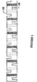
- FIG. 1 shows one exemplary embodiment of a single-molded element not within the scope of the present invention in which the overall cylindrical structure 10 include a plurality of evenly spaced, rectangular channels 20 therein.
- the channels may be formed during molding or may be formed after molding, for example by micro-machining, laser and/or chemical etching techniques. Shaded areas denote channels facing the view while dotted lines denote channels on the back side of the cylindrical structure. It will be apparent that the channels need not be evenly spaced over the exterior surface of the element and, moreover, that these channels may be of the same or similar shape and/or dimensions or that their dimensions may vary across the longitudinal axis of the device.
- the channels are preferably perpendicular to the longitudinal axis of the device.
- one or more of the channels may be angled anywhere from 0 to 90° (or any value therebetween) relative to the plane of the longitudinal axis of the device.
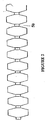
- FIG. 2 shows yet another exemplary single-molded element not within the scope of the present invention having the appearance of a series of similarly shaped elements 40 linked to one another.
- the linked elements are not separate components.
- these linked elements can be virtually any three-dimensional shape, for example, sphere-like, ovoid, conical, pyramidal, disks, blocks (including cubes and blocks with more than 6 sides), and the like. Different shapes and/or sizes can be used in the same vaso-occlusive element.
- the nature of the linking component e.g ., dimension, hollowness, etc.
- FIG. 3 shows an exemplary embodiment of an injection-molded vaso-occlusive element formed from a plurality of individually molded elements linked together after molding. Like FIG. 2 , FIG. 3 shows an embodiment in which the overall appearance of the device is a series of similarly shaped elements linked to each other. Again, the shaped components can be any three-dimensional shape and each individual component can vary in shape and/or dimension.
- the injection-molded vaso-occlusive devices be comprised of a variety of material and may take on a variety of shapes and/or configurations. Braided absorbable vaso-occlusive devices are also included within the scope of the present invention. It is further within the scope of this invention that the vaso-occlusive device comprise shapes or structures other than those shown in the Figures, for examples, spheres, ellipses, spirals, figure-8 shapes, etc. Stretch-resistant configurations can also be designed and manufactured, for example, by including structural features (e.g ., lines, channels, etc.) in the mold that impart stretch-resistancy.
- structural features e.g ., lines, channels, etc.
- Configurations described herein can also be created by micro-machining channels at desired locations of an essentially tube-like structure. It will also be apparent that the vaso-occlusive elements described herein need not be linear and that curves or angles can ben introduced into the overall configuration by using suitable molds, post-molding modifications (e.g ., heating at a temperature above the glass transition temperature of the polymeric material or plasticizing to achieve desired turns or angles) and/or by providing suitable angled linkages between individual molded elements. These linkages can be provided by any suitable method including, but not limited to, soldering, friction, mechanical interlocks, adhesives, solvent bonding, stringing together, ultrasonic welding, thermal welding and the like.
- the injection-molded elements comprise an absorbable polymer suitable in occluding aneurysms.
- absorbable refers to any agent which, over time, is no longer identifiable at the site of application in the form it was injected, for example having been removed via degradation, metabolism, dissolving or any passive or active removal procedure.
- Absorbable vaso-occlusive devices are described in detail in co-owned patent application entitled “Absorbable Implantable Vaso-Occlusive Member,” filed even date herewith.
- the polymer is absorbable, for example, polyglycolide, poly-L-lactide, poly(g-ethyl glutamates), polyphosphazene, polysaccharides, polyorthoesters, polycaprolactone, polyhydroxybutyrate, polydioxanone, polycarbonates, polyanhydrides, copolymers of one of these polymers and/or blends of these polymers.
- bioabsorbable proteins include synthetic and polysaccharide biodegradable hydrogels, collagen, elastin, fibrinogen, fibronectin, vitronectin, laminin and gelatin. Many of these materials are commercially available.
- Fibrin-containing compositions are commercially available, for example from Baxter. Collagen containing compositions are commercially available, for example from Cohesion Technologies, Inc., Palo Alto, California. Fibrinogen-containing compositions are described, for example, in U.S. Patent Nos. 6,168,788 and 5,290,552 . As will be readily apparent, absorbable materials can be used alone or in any combination with each other and/or other materials.
- injection-molded vaso-occlusive devices of the present invention can also be used in combination with additional components.
- lubricious materials e.g ., hydrophilic
- bioactive materials may also be included.
- bioactive refers to any agent which exhibits effects in vivo, for example a thrombotic agent, a therapeutic agent or the like.
- Non-limiting examples of bioactive materials include cytokines; extracellular matrix molecules (e.g .,collagen); trace metals (e.g ., copper); and other molecules that stabilize thrombus formation or inhibit clot lysis (e.g ., proteins or functional fragments of proteins, including but not limited to Factor XIII, ⁇ 2 -antiplasmin, plasminogen activator inhibitor-1 (PAI-1) or the like).
- cytokines which may be used alone or in combination in the practice of the present invention include, basic fibroblast growth factor (bFGF), platelet derived growth factor (PDGF), vascular endothelial growth factor (VEGF), transforming growth factor beta (TGF- ⁇ ) and the like.
- Cytokines, extracellular matrix molecules and thrombus stabilizing molecules are commercially available from several vendors such as, for example, Genzyme (Framingham, MA), Genentech (South San Francisco, CA), Amgen (Thousand Oaks, CA), R&D Systems and Immunex (Seattle, WA). Additionally, bioactive polypeptides can be synthesized recombinantly as the sequence of many of these molecules are also available, for example, from the GenBank database. Thus, it is intended that the invention include use of DNA or RNA encoding any of the bioactive molecules. Cells (e.g ., fibroblasts, stem cells, etc.) can also be included.
- Such cells may be genetically modified.
- molecules having similar biological activity as wild-type or purified cytokines, extracellular matrix molecules and thrombus-stabilizing proteins (e.g., recombinantly produced or mutants thereof) and nucleic acid encoding these molecules are intended to be used within the spirit and scope of the invention.
- the amount and concentration of liquid embolic and/or other bioactive materials useful in the practice of the invention can be readily determined by a skilled operator and it will be understood that any combination of materials, concentration or dosage can be used, so long as it is not harmful to the subject.
- the injection-molded devices may be coated or mixed with radio-opaque materials such as metals (e.g . tantalum; gold or platinum particles); barium sulfate; bismuth subcarbonate; or the like.
- radio-opaque materials such as metals (e.g . tantalum; gold or platinum particles); barium sulfate; bismuth subcarbonate; or the like.
- vaso-occlusive devices described are also provided.
- the vaso-occlusive devices described herein are typically formed by injection molding techniques as described above to form a size and shape suitable for fitting snugly within a vascular cavity (e.g., an aneurysm, or perhaps, a fistula).
- embolic compositions described herein are often introduced into a selected site using the procedure outlined below. This procedure may be used in treating a variety of maladies. For instance in the treatment of an aneurysm, the aneurysm itself will be filled (partially or fully) with the compositions described herein.
- the mechanism will be such as to be capable of being advanced entirely through the catheter to place injection-molded vaso-occlusive device at the target site but yet with a sufficient portion of the distal end of the delivery mechanism protruding from the distal end of the catheter to enable detachment of the implantable vaso-occlusive device.
- the delivery mechanism will normally be about 100-200 cm in length, more normally 130-180 cm in length.
- the diameter of the delivery mechanism is usually in the range of 0.25 to about 0.90 mm.
- the liquid embolics and/or occlusive devices described herein are typically loaded into a carrier for introduction into the delivery catheter and introduced to the chosen site using the procedure outlined below.
- This procedure may be used in treating a variety of maladies.
- the aneurysm itself may be filled with the embolics (e.g ., mechanical devices, injection-molded vaso-occlusive members and/or liquid embolics and bioactive materials) which cause formation of an emboli and, at some later time, is at least partially replaced by neovascularized collagenous material formed around the implanted vaso-occlusive devices.
- the embolics e.g ., mechanical devices, injection-molded vaso-occlusive members and/or liquid embolics and bioactive materials
- a selected site is reached through the vascular system using a collection of specifically chosen catheters and/or guide wires. It is clear that should the site be in a remote site, e.g., in the brain, methods of reaching this site are somewhat limited.
- One widely accepted procedure is found in U.S. Patent No. 4,994,069 to Ritchart, et al. It utilizes a fine endovascular catheter such as is found in U.S. Patent No. 4,739,768, to Engelson .
- a large catheter is introduced through an entry site in the vasculature. Typically, this would be through a femoral artery in the groin.
- Other entry sites sometimes chosen are found in the neck and are in general well known by physicians who practice this type of medicine.
- a guiding catheter is then used to provide a safe passageway from the entry site to a region near the site to be treated.
- a guiding catheter would be chosen which would extend from the entry site at the femoral artery, up through the large arteries extending to the heart, around the heart through the aortic arch, and downstream through one of the arteries extending from the upper side of the aorta.
- a guidewire and neurovascular catheter such as that described in the Engelson patent are then placed through the guiding catheter. Once the distal end of the catheter is positioned at the site, often by locating its distal end through the use of radiopaque marker material and fluoroscopy, the catheter is cleared. For instance, if a guidewire has been used to position the catheter, it is withdrawn from the catheter and then the assembly, for example including the absorbable vaso-occlusive device at the distal end, is advanced through the catheter.
- the absorbable vaso-occlusive device is extruded, for example by loading onto a pusher wire.
- the vaso-occlusive device is loaded onto the pusher wire via a mechanically or electrolytically cleavable junction (e.g. , a GDC-type junction that can be severed by application of heat, electrolysis, electrodynamic activation or other means).
- the vaso-occlusive device can be designed to include multiple detachment points, as described in co-owned U.S. Patent Application titled "LIGHT-ACTIVATED MULTI-POINT DETACHMENT MECHANISM". They are held in place by gravity, shape, size, volume, magnetic field or combinations thereof.
Abstract
Description
- Compositions and methods for repair of aneurysms are described. In particular, injection-molded polymeric vaso-occlusive devices are disclosed, as are methods of making and using these devices.
- An aneurysm is a dilation of a blood vessel (similar to a balloon) that poses a risk to health from the potential for rupture, clotting, or dissecting. Rupture of an aneurysm in the brain causes stroke, and rupture of an aneurysm in the abdomen causes shock. Cerebral aneurysms are usually detected in patients as the result of a seizure or hemorrhage and can result in significant morbidity or mortality.
- There are a variety of materials and devices which have been used for treatment of aneurysms, including platinum and stainless steel microcoils, polyvinyl alcohol sponges (Ivalone), and other mechanical devices. For example, vaso-occlusion devices are surgical implements or implants that are placed within the vasculature of the human body, typically via a catheter, either to block the flow of blood through a vessel making up that portion of the vasculature through the formation of an embolus or to form such an embolus within an aneurysm stemming from the vessel. One widely used vaso-occlusive device is a helical wire coil having windings which may be dimensioned to engage the walls of the vessels. (See, e.g.,
U.S. Patent No. 4,994,069 to Ritchart et al. ) Other less stiff helically coiled devices have been described, as well as those involving woven braids. -
U.S. Pat. No. 5,354,295 and its parent,U.S. Pat. No. 5,122,136, both to Guglielmi et al. , describe an electrolytically detachable embolic device. Vaso-occlusive coils having little or no inherent secondary shape have also been described. For instance, co-ownedU.S. Patent Numbers 5,690,666 and5,826,587 by Berenstein et al. , describes coils having little or no shape after introduction into the vascular space. - Liquid embolics, such as cyanoacrylate glues and fibrin sealants, have also been used in animal and human subjects. See, e.g., Interventional Radiology, Dandlinger et al, ed., Thieme, N.Y., 1990:295-313; Suga et al. (1992) No Shinkei Geka 20(8):865-873; Moringlane et al. (1987) Surg Neurol 28(5):361-366; Moringlane et al. (1988) Acta Neurochir Suppl. (Wein) 43:193-197. Of these liquid embolics, cyanoacrylate glues are the only liquid embolics currently available to neurosurgeons. However, chronic inflammation is typically seen with cyanoacrylate treatments (Herrera et al. (1999) Neurol Med Chir (Tokyo) 39(2):134-139) and the degradation product, formaldehyde, is highly toxic to the neighboring tissues. See, Vinters et al (1995) Neuroradiology 27:279-291. Another disadvantage of cyanoacrylate materials is that the polymer will adhere both to the blood vessel and to the tip of the catheter. Thus physicians must retract the catheter immediately after injection of the cyanoacrylate embolic material or risk adhesion of the cyanoacrylate and the catheter to the vessel.
- Document
WO 99/23954 - Document
WO 01/06950 WO 92/21400 - None of these documents describe injection molded vascular occlusion elements having the characteristics described herein or methods of making and using such devices.
- Thus, this invention includes novel occlusive compositions as well as methods of using and making these compositions.
- The invention is defined by the subject-matter of independent claims 1 and 2.
- In preferred embodiments, the polymeric material is absorbable, for example, polyglycolide, poly-L-lactide, poly(g-ethyl glutamates), polyphosphazene, polysaccharides, polyorthoesters, polycaprolactone, polyhydroxybutyrate, polydioxanone, polycarbonates, polyanhydrides, copolymers or blends thereof, collagen, elastin, fibrinogen, fibronectin, vitronectin, laminin, gelatin and combinations thereof. The three-dimensional configuration can be any shape, for example, a cylindrical configuration having a longitudinal axis or a plurality of shaped structures (e.g., ovals, spheres, cones, pyramids, blocks or combinations of these shapes) linked in series.
- The three-dimensional configuration can further include additional modifications, for example a cylindrical device may be produced with a plurality of channels therein (e.g, channels perpendicular to the longitudinal axis of the device).
- In certain embodiments, any of the methods described herein further comprise the step of providing, on the injection molded element, a severable junction detachably connected to a pusher element. In certain embodiments, the severable junction(s) are, an electrolytically detachable assembly adapted to detach by imposition of a current on said pusher element; a mechanically detachable assembly adapted to detach by movement or pressure imposed on or within said pusher element; a thermally detachable assembly adapted to detach by localized delivery of heat to said junction; a radiation detachable assembly adapted to detach by delivery of electromagnetic radiation to said junction or combinations thereof.
- Any of the methods described herein can further comprise additional production steps, for instance, micro-machining the injection-molded element; chemically etching the injection-molded element; laser cutting the injection-molded element; and linking a plurality of injection-molded elements together (e.g., by soldering, interference fitting, friction fitting, stringing, ultrasonic welding, thermal welding and solvent bonding). More than one additional production steps can be performed on the same device. Additionally, the polymer can be blended with one or more additional materials, for example, one or more radio-opaque materials (e.g., tantalum, tantalum oxide, tungsten, bismuth oxide, barium sulfate, platinum, and gold) and/or one or more bioactive materials. In certain embodiments, the injection molding comprises insert molding a metallic wire within the three-dimensional configuration.
- In another aspect, the invention includes a vaso-occlusive device produced by any of the methods described herein.
- In yet another aspect, the invention includes a vaso-occlusive device comprising at least one polymeric material, wherein said device is formed into and deployed in a three-dimensional configuration. Preferably, the device is formed by injection molding techniques. Furthermore, in preferred embodiments, the vaso-occlusive device comprises at least one absorbable or biodegradable polymer, for example, polyglycolide, poly-L-lactide, poly(g-ethyl glutamates), polyphosphazene, polysaccharides, polyorthoesters, polycaprolactone, polyhydroxybutyrate, polydioxanone, polycarbonates, polyanhydrides, copolymers or blends thereof, collagen, elastin, fibrinogen, fibronectin, vitronectin, laminin, gelatin and combinations thereof. The three-dimensional configuration can be any shape, for example, a cylindrical configuration having a longitudinal axis or a plurality of shaped structures (e.g., ovals, spheres, cones, pyramids, blocks or combinations of these shapes) linked in series.
- The three-dimensional configuration can further include additional modifications, for example a cylindrical device may include a plurality of channels therein (e.g, channels perpendicular to the longitudinal axis of the device).
- In certain embodiments, any of the devices described herein further comprise a severable junction detachably connected to a pusher element. In certain embodiments, the severable junction(s) are, an electrolytically detachable assembly adapted to detach by imposition of a current on said pusher element; a mechanically detachable assembly adapted to detach by movement or pressure imposed on or within said pusher element; a thermally detachable assembly adapted to detach by localized delivery of heat to said junction; a radiation detachable assembly adapted to detach by delivery of electromagnetic radiation to said junction or combinations thereof.
- Any of the devices described herein can be further modified, for instance by, micro-machining the injection-molded element; chemically etching the injection-molded element; laser cutting the injection-molded element; and/or linking a plurality of injection-molded elements together (e.g., by soldering, interference fitting, friction fitting, stringing, ultrasonic welding, thermal welding and solvent bonding). A single device may include one or more of such modifications. Additionally, the device may include one or more additional materials, for example, one or more radio-opaque materials (e.g., tantalum, tantalum oxide, tungsten, bismuth oxide, barium sulfate, platinum, and gold) and/or bioactive materials. In certain embodiments, the injection molding comprises insert molding a metallic wire within the three-dimensional configuration.
- These and other embodiments of the subject invention will readily occur to those of skill in the art in light of the disclosure herein.
-
-
FIG. 1 depicts an exemplary single-molded vaso-occlusive device not in accordance with the invention having a generally tubular and linear configuration with channels spaced along the length of the device. -
FIG. 2 depicts another exemplary single-molded vaso-occlusive device not in accordance with the invention generally configuration of a series of shaped elements linked to one another. -
FIG. 3 depicts an exemplary string of molded elements linked together to provide an overall coil-like configuration. - Occlusive (e.g., embolic) compositions are described. The compositions described herein find use in vascular and neurovascular indications and are particularly useful in treating aneurysms, for example small-diameter, curved or otherwise difficult to access vasculature, for example cerebral aneurysms. Methods of making and using these vaso-occlusive elements also an aspects of this invention. The compositions and methods described herein are particularly useful when the element is comprised primarily or entirely of polymeric material, for example, absorbable polymeric material.
- Advantages of the present invention include, but are not limited to, (i) production of polymeric non-coil elements; (ii) production of polymeric (e.g., partially or fully absorbable vaso-occlusive devices) without the need for winding and/or heat-setting which may be technically difficult; (iii) reducing or eliminating variation (e.g., diameter, strength, etc.) of polymeric vaso-occlusive elements; and (iv) cost-effective production of polymeric elements, for example by use of automation.
- It must be noted that, as used in this specification and the appended claims, the singular forms "a", "an", and "the" include plural referents unless the content clearly dictates otherwise. Thus, for example, reference to "a polymer" includes a mixture of two or more such polymers and the like.
- Thus, described herein are novel injection-molded vaso-occlusive elements and novel methods of manufacturing these elements. Unlike previously described polymeric vaso-occlusive elements, the devices described herein do not have a primary helical geometry (i.e. are not made in a two-step process of helically winding a wire into a coil and then winding the coil into a three-dimensional shape). Rather, the claimed elements are not helically wound and are produced by injection molding, reaction injection molding, extrusion or the like. Further, unlike known vaso-occlusive elements which assume a secondary configuration (e.g., three-dimensional configuration) after extrusion from the deployment catheter, the injection-molded elements described herein typically are formed into their three-dimensional configurations prior to deployment and are delivered and deployed in these secondary configurations. Additionally, unlike most non-injection molded polymeric devices, the cross-sectional configurations of certain embodiments of the injection-molded devices described herein typically vary along the length of the device. In other words, in contrast to regularly wound helical coils, many of the injection molded devices will not have a continuous cross-section along the longitudinal axis.
- As used herein the term "injection molded" refers broadly to any technique for forming polymers into desired configurations including extrusion, molding, insert molding, reaction molding and the like. Such techniques are known in the art. Furthermore, micro-machining techniques (e.g., laser or other micro-machining) can also be employed in the manufacture of the vaso-occlusive devices described herein, for example to create holes and/or channels in the molded material.
- Thus, in certain embodiments, the vaso-occlusive elements described herein are formed using a mold. The design of molds for injections, runners (hot and cold), gates, vents, cavity layout, and ejection systems is also within the purview of the skilled artisan in view of the teachings herein which, for the first time, apply injection molding techniques to the manufacture and use of vaso-occlusive devices. The elements produced by injection molding are significantly less prone to variability (e.g., in diameter and/or tensile strength) while maintaining the desired occlusive and/or flexibility characteristics. Suitable molding processes include conventional molding process (where a coolant such as water or oil is circulated through the mold continuously while mold temperature is regulated by a controller such as a thermolator or chiller); pulsed cooling processes (where a manifold is designed to pulse cold water through the system at selected times, for example, once the desired temperature is reached); gas-assisted molding; multi-live feed processes; co-injection and sandwich molding and the like. For a review of injection molding techniques, see, for example, Medical Device & Diagnostic Industry Magazine, April 1998 cover story and accompanying articles and columns.
- The vaso-occlusive elements of the present invention have a plurality of molded elements which are linked to form the desired configuration.
FIG. 1 shows one exemplary embodiment of a single-molded element not within the scope of the present invention in which the overallcylindrical structure 10 include a plurality of evenly spaced,rectangular channels 20 therein. The channels may be formed during molding or may be formed after molding, for example by micro-machining, laser and/or chemical etching techniques. Shaded areas denote channels facing the view while dotted lines denote channels on the back side of the cylindrical structure. It will be apparent that the channels need not be evenly spaced over the exterior surface of the element and, moreover, that these channels may be of the same or similar shape and/or dimensions or that their dimensions may vary across the longitudinal axis of the device. As shown inFIG. 1 , the channels are preferably perpendicular to the longitudinal axis of the device. Alternatively, one or more of the channels may be angled anywhere from 0 to 90° (or any value therebetween) relative to the plane of the longitudinal axis of the device. -
FIG. 2 shows yet another exemplary single-molded element not within the scope of the present invention having the appearance of a series of similarly shaped elements 40 linked to one another. In single-molded embodiments as shown inFIG. 2 , the linked elements are not separate components. Further, it will be apparent that these linked elements can be virtually any three-dimensional shape, for example, sphere-like, ovoid, conical, pyramidal, disks, blocks (including cubes and blocks with more than 6 sides), and the like. Different shapes and/or sizes can be used in the same vaso-occlusive element. Additionally, the nature of the linking component (e.g., dimension, hollowness, etc.) can vary between different elements. -
FIG. 3 shows an exemplary embodiment of an injection-molded vaso-occlusive element formed from a plurality of individually molded elements linked together after molding. LikeFIG. 2 ,FIG. 3 shows an embodiment in which the overall appearance of the device is a series of similarly shaped elements linked to each other. Again, the shaped components can be any three-dimensional shape and each individual component can vary in shape and/or dimension. - Thus, the injection-molded vaso-occlusive devices be comprised of a variety of material and may take on a variety of shapes and/or configurations. Braided absorbable vaso-occlusive devices are also included within the scope of the present invention. It is further within the scope of this invention that the vaso-occlusive device comprise shapes or structures other than those shown in the Figures, for examples, spheres, ellipses, spirals, figure-8 shapes, etc. Stretch-resistant configurations can also be designed and manufactured, for example, by including structural features (e.g., lines, channels, etc.) in the mold that impart stretch-resistancy.
- Configurations described herein can also be created by micro-machining channels at desired locations of an essentially tube-like structure. It will also be apparent that the vaso-occlusive elements described herein need not be linear and that curves or angles can ben introduced into the overall configuration by using suitable molds, post-molding modifications (e.g., heating at a temperature above the glass transition temperature of the polymeric material or plasticizing to achieve desired turns or angles) and/or by providing suitable angled linkages between individual molded elements. These linkages can be provided by any suitable method including, but not limited to, soldering, friction, mechanical interlocks, adhesives, solvent bonding, stringing together, ultrasonic welding, thermal welding and the like.
- In one aspect, the injection-molded elements comprise an absorbable polymer suitable in occluding aneurysms. The term "absorbable" refers to any agent which, over time, is no longer identifiable at the site of application in the form it was injected, for example having been removed via degradation, metabolism, dissolving or any passive or active removal procedure. Absorbable vaso-occlusive devices are described in detail in co-owned patent application entitled "Absorbable Implantable Vaso-Occlusive Member," filed even date herewith. In preferred embodiments, the polymer is absorbable, for example, polyglycolide, poly-L-lactide, poly(g-ethyl glutamates), polyphosphazene, polysaccharides, polyorthoesters, polycaprolactone, polyhydroxybutyrate, polydioxanone, polycarbonates, polyanhydrides, copolymers of one of these polymers and/or blends of these polymers. Non-limiting examples of bioabsorbable proteins include synthetic and polysaccharide biodegradable hydrogels, collagen, elastin, fibrinogen, fibronectin, vitronectin, laminin and gelatin. Many of these materials are commercially available. Fibrin-containing compositions are commercially available, for example from Baxter. Collagen containing compositions are commercially available, for example from Cohesion Technologies, Inc., Palo Alto, California. Fibrinogen-containing compositions are described, for example, in
U.S. Patent Nos. 6,168,788 and5,290,552 . As will be readily apparent, absorbable materials can be used alone or in any combination with each other and/or other materials. - Furthermore, the injection-molded vaso-occlusive devices of the present invention can also be used in combination with additional components. For example, lubricious materials (e.g., hydrophilic) materials may be used to coat the injection-molded device to help facilitate delivery. One or more bioactive materials may also be included. The term "bioactive" refers to any agent which exhibits effects in vivo, for example a thrombotic agent, a therapeutic agent or the like. Non-limiting examples of bioactive materials include cytokines; extracellular matrix molecules (e.g.,collagen); trace metals (e.g., copper); and other molecules that stabilize thrombus formation or inhibit clot lysis (e.g., proteins or functional fragments of proteins, including but not limited to Factor XIII, α2-antiplasmin, plasminogen activator inhibitor-1 (PAI-1) or the like). Non-limiting examples of cytokines which may be used alone or in combination in the practice of the present invention include, basic fibroblast growth factor (bFGF), platelet derived growth factor (PDGF), vascular endothelial growth factor (VEGF), transforming growth factor beta (TGF-β) and the like. Cytokines, extracellular matrix molecules and thrombus stabilizing molecules (e.g., Factor XIII, PAI-1, etc.) are commercially available from several vendors such as, for example, Genzyme (Framingham, MA), Genentech (South San Francisco, CA), Amgen (Thousand Oaks, CA), R&D Systems and Immunex (Seattle, WA). Additionally, bioactive polypeptides can be synthesized recombinantly as the sequence of many of these molecules are also available, for example, from the GenBank database. Thus, it is intended that the invention include use of DNA or RNA encoding any of the bioactive molecules. Cells (e.g., fibroblasts, stem cells, etc.) can also be included. Such cells may be genetically modified. Furthermore, it is intended, although not always explicitly stated, that molecules having similar biological activity as wild-type or purified cytokines, extracellular matrix molecules and thrombus-stabilizing proteins (e.g., recombinantly produced or mutants thereof) and nucleic acid encoding these molecules are intended to be used within the spirit and scope of the invention. Further, the amount and concentration of liquid embolic and/or other bioactive materials useful in the practice of the invention can be readily determined by a skilled operator and it will be understood that any combination of materials, concentration or dosage can be used, so long as it is not harmful to the subject.
- It also may be desirable to include one or more radio-opaque materials for use in visualizing the devices in situ. Thus, the injection-molded devices may be coated or mixed with radio-opaque materials such as metals (e.g. tantalum; gold or platinum particles); barium sulfate; bismuth subcarbonate; or the like.
- Methods of making the polymeric vaso-occlusive devices described are also provided. The vaso-occlusive devices described herein are typically formed by injection molding techniques as described above to form a size and shape suitable for fitting snugly within a vascular cavity (e.g., an aneurysm, or perhaps, a fistula).
- The embolic compositions described herein are often introduced into a selected site using the procedure outlined below. This procedure may be used in treating a variety of maladies. For instance in the treatment of an aneurysm, the aneurysm itself will be filled (partially or fully) with the compositions described herein.
- Conventional catheter insertion and navigational techniques involving guidewires or flow-directed devices may be used to access the site with a catheter. The mechanism will be such as to be capable of being advanced entirely through the catheter to place injection-molded vaso-occlusive device at the target site but yet with a sufficient portion of the distal end of the delivery mechanism protruding from the distal end of the catheter to enable detachment of the implantable vaso-occlusive device. For use in peripheral or neural surgeries, the delivery mechanism will normally be about 100-200 cm in length, more normally 130-180 cm in length. The diameter of the delivery mechanism is usually in the range of 0.25 to about 0.90 mm. Briefly, the liquid embolics and/or occlusive devices described herein are typically loaded into a carrier for introduction into the delivery catheter and introduced to the chosen site using the procedure outlined below. This procedure may be used in treating a variety of maladies. For instance, in treatment of an aneurysm, the aneurysm itself may be filled with the embolics (e.g., mechanical devices, injection-molded vaso-occlusive members and/or liquid embolics and bioactive materials) which cause formation of an emboli and, at some later time, is at least partially replaced by neovascularized collagenous material formed around the implanted vaso-occlusive devices.
- A selected site is reached through the vascular system using a collection of specifically chosen catheters and/or guide wires. It is clear that should the site be in a remote site, e.g., in the brain, methods of reaching this site are somewhat limited. One widely accepted procedure is found in
U.S. Patent No. 4,994,069 to Ritchart, et al. It utilizes a fine endovascular catheter such as is found inU.S. Patent No. 4,739,768, to Engelson . First of all, a large catheter is introduced through an entry site in the vasculature. Typically, this would be through a femoral artery in the groin. Other entry sites sometimes chosen are found in the neck and are in general well known by physicians who practice this type of medicine. Once the introducer is in place, a guiding catheter is then used to provide a safe passageway from the entry site to a region near the site to be treated. For instance, in treating a site in the human brain, a guiding catheter would be chosen which would extend from the entry site at the femoral artery, up through the large arteries extending to the heart, around the heart through the aortic arch, and downstream through one of the arteries extending from the upper side of the aorta. A guidewire and neurovascular catheter such as that described in the Engelson patent are then placed through the guiding catheter. Once the distal end of the catheter is positioned at the site, often by locating its distal end through the use of radiopaque marker material and fluoroscopy, the catheter is cleared. For instance, if a guidewire has been used to position the catheter, it is withdrawn from the catheter and then the assembly, for example including the absorbable vaso-occlusive device at the distal end, is advanced through the catheter. - Once the selected site has been reached, the absorbable vaso-occlusive device is extruded, for example by loading onto a pusher wire. Preferably, the vaso-occlusive device is loaded onto the pusher wire via a mechanically or electrolytically cleavable junction (e.g., a GDC-type junction that can be severed by application of heat, electrolysis, electrodynamic activation or other means). Additionally, the vaso-occlusive device can be designed to include multiple detachment points, as described in co-owned U.S. Patent Application titled "LIGHT-ACTIVATED MULTI-POINT DETACHMENT MECHANISM". They are held in place by gravity, shape, size, volume, magnetic field or combinations thereof.
- Modifications of the procedure and vaso-occlusive devices described above, and the methods of using them in keeping with this invention will be apparent to those having skill in this mechanical and surgical art. These variations are intended to be within the scope of the claims that follow.
Claims (5)
- A method for producing an injection-molded vaso-occlusive element for occluding a vasculature, the method comprising the steps of:individually molding a plurality of elements; andlinking the plurality of individually molded elements together by a linking element after molding, the linking element being a polymeric wire or a ductile metallic wire,whereinthe individually molded elements have each a three-dimensional shape being ovoid, spherical, conical or pyramidal; andthe individually molded elements being linked together end to end by the linking element.
- An injection-molded vaso-occlusive element for occluding a vasculature, comprising:a plurality of individually molded elements; anda linking element, the linking element being a polymeric wire or a ductile metallic wire, wherein the plurality of individually molded elements being linked together by the linking element,whereinthe individually molded elements have each a three-dimensional shape being ovoid, spherical, conical or pyramidal; andthe individually molded elements being linked together end to end by the linking element.
- The vaso-cclusive device of claim 2, wherein the vaso-occlusive device comprises at least one absorbable or biodegradable polymer.
- The method of claim 1, wherein the absorbable polymeric material is selected from the group consisting of polyglycolide, poly-L-lactide, poly(g-ethyl glutamates), polyphosphazene, polysaccharides, polyorthoesters, polycaprolactone, polyhydroxybutyrate, polydioxanone, polycarbonates, polyanhydrides, copolymers or blends thereof, collagen, elastin, fibrinogen, fibronectin, vitronectin, laminin, gelatin and combinations thereof.
- The method of any of claims 1 or 4, further comprising the step of blending one or more radio-opaque materials with the polymer.
Applications Claiming Priority (3)
| Application Number | Priority Date | Filing Date | Title |
|---|---|---|---|
| US09/866,892 US6921410B2 (en) | 2001-05-29 | 2001-05-29 | Injection molded vaso-occlusive elements |
| US866892 | 2001-05-29 | ||
| PCT/US2002/017284 WO2002096273A2 (en) | 2001-05-29 | 2002-05-29 | Injection molded vaso-occlusive elements |
Publications (3)
| Publication Number | Publication Date |
|---|---|
| EP1395327A2 EP1395327A2 (en) | 2004-03-10 |
| EP1395327A4 EP1395327A4 (en) | 2008-06-25 |
| EP1395327B1 true EP1395327B1 (en) | 2012-04-11 |
Family
ID=25348660
Family Applications (1)
| Application Number | Title | Priority Date | Filing Date |
|---|---|---|---|
| EP02746465A Expired - Lifetime EP1395327B1 (en) | 2001-05-29 | 2002-05-29 | Injection molded vaso-occlusive elements |
Country Status (8)
| Country | Link |
|---|---|
| US (1) | US6921410B2 (en) |
| EP (1) | EP1395327B1 (en) |
| JP (1) | JP4938208B2 (en) |
| AT (1) | ATE552785T1 (en) |
| AU (1) | AU2002316185A1 (en) |
| CA (1) | CA2447486C (en) |
| ES (1) | ES2384375T3 (en) |
| WO (1) | WO2002096273A2 (en) |
Families Citing this family (73)
| Publication number | Priority date | Publication date | Assignee | Title |
|---|---|---|---|---|
| US20060292206A1 (en) | 2001-11-26 | 2006-12-28 | Kim Steven W | Devices and methods for treatment of vascular aneurysms |
| US7318833B2 (en) | 2001-12-19 | 2008-01-15 | Nmt Medical, Inc. | PFO closure device with flexible thrombogenic joint and improved dislodgement resistance |
| WO2003053493A2 (en) | 2001-12-19 | 2003-07-03 | Nmt Medical, Inc. | Septal occluder and associated methods |
| WO2003082076A2 (en) | 2002-03-25 | 2003-10-09 | Nmt Medical, Inc. | Patent foramen ovale (pfo) closure clips |
| US7060083B2 (en) * | 2002-05-20 | 2006-06-13 | Boston Scientific Scimed, Inc. | Foldable vaso-occlusive member |
| WO2003103476A2 (en) | 2002-06-05 | 2003-12-18 | Nmt Medical, Inc. | Patent foramen ovale (pfo) closure device with radial and circumferential support |
| WO2004037333A1 (en) | 2002-10-25 | 2004-05-06 | Nmt Medical, Inc. | Expandable sheath tubing |
| US7481821B2 (en) | 2002-11-12 | 2009-01-27 | Thomas J. Fogarty | Embolization device and a method of using the same |
| WO2004052213A1 (en) | 2002-12-09 | 2004-06-24 | Nmt Medical, Inc. | Septal closure devices |
| US20040260382A1 (en) | 2003-02-12 | 2004-12-23 | Fogarty Thomas J. | Intravascular implants and methods of using the same |
| US8480706B2 (en) | 2003-07-14 | 2013-07-09 | W.L. Gore & Associates, Inc. | Tubular patent foramen ovale (PFO) closure device with catch system |
| US9861346B2 (en) * | 2003-07-14 | 2018-01-09 | W. L. Gore & Associates, Inc. | Patent foramen ovale (PFO) closure device with linearly elongating petals |
| US7678123B2 (en) | 2003-07-14 | 2010-03-16 | Nmt Medical, Inc. | Tubular patent foramen ovale (PFO) closure device with catch system |
| US20050015110A1 (en) | 2003-07-18 | 2005-01-20 | Fogarty Thomas J. | Embolization device and a method of using the same |
| DE602004017750D1 (en) | 2003-08-19 | 2008-12-24 | Nmt Medical Inc | Expandable lock hose |
| US20050273119A1 (en) | 2003-12-09 | 2005-12-08 | Nmt Medical, Inc. | Double spiral patent foramen ovale closure clamp |
| US7871419B2 (en) | 2004-03-03 | 2011-01-18 | Nmt Medical, Inc. | Delivery/recovery system for septal occluder |
| US20050267524A1 (en) | 2004-04-09 | 2005-12-01 | Nmt Medical, Inc. | Split ends closure device |
| US8361110B2 (en) | 2004-04-26 | 2013-01-29 | W.L. Gore & Associates, Inc. | Heart-shaped PFO closure device |
| US7842053B2 (en) | 2004-05-06 | 2010-11-30 | Nmt Medical, Inc. | Double coil occluder |
| US8308760B2 (en) | 2004-05-06 | 2012-11-13 | W.L. Gore & Associates, Inc. | Delivery systems and methods for PFO closure device with two anchors |
| JP2007535997A (en) | 2004-05-07 | 2007-12-13 | エヌエムティー メディカル, インコーポレイティッド | Capturing mechanism of tubular septal occluder |
| US20050267510A1 (en) * | 2004-05-26 | 2005-12-01 | Nasser Razack | Device for the endovascular treatment of intracranial aneurysms |
| US7749242B2 (en) | 2004-06-21 | 2010-07-06 | Boston Scientific Scimed, Inc. | Expanding vaso-occlusive device |
| US7879064B2 (en) | 2004-09-22 | 2011-02-01 | Micro Therapeutics, Inc. | Medical implant |
| ATE448737T1 (en) | 2004-09-22 | 2009-12-15 | Dendron Gmbh | DEVICE FOR IMPLANTING MICROWL COILS |
| WO2006036837A2 (en) | 2004-09-24 | 2006-04-06 | Nmt Medical, Inc. | Occluder device double securement system for delivery/recovery of such occluder device |
| US20060178697A1 (en) | 2005-02-04 | 2006-08-10 | Carr-Brendel Victoria E | Vaso-occlusive devices including non-biodegradable biomaterials |
| US20060200190A1 (en) | 2005-03-02 | 2006-09-07 | Lorenzo Juan A | Embolic coil with twisted wire |
| EP1868507A1 (en) | 2005-03-18 | 2007-12-26 | NMT Medical, Inc. | Catch member for pfo occluder |
| US8002789B2 (en) | 2005-05-31 | 2011-08-23 | Stryker Corporation | Stretch-resistant vaso-occlusive devices with flexible detachment junctions |
| WO2007073566A1 (en) | 2005-12-22 | 2007-06-28 | Nmt Medical, Inc. | Catch members for occluder devices |
| US8551135B2 (en) | 2006-03-31 | 2013-10-08 | W.L. Gore & Associates, Inc. | Screw catch mechanism for PFO occluder and method of use |
| JP2009532125A (en) | 2006-03-31 | 2009-09-10 | エヌエムティー メディカル, インコーポレイティッド | Deformable flap catch mechanism for occluder equipment |
| US8870913B2 (en) | 2006-03-31 | 2014-10-28 | W.L. Gore & Associates, Inc. | Catch system with locking cap for patent foramen ovale (PFO) occluder |
| CA2649702C (en) | 2006-04-17 | 2014-12-09 | Microtherapeutics, Inc. | System and method for mechanically positioning intravascular implants |
| KR20100015520A (en) | 2007-03-13 | 2010-02-12 | 마이크로 테라퓨틱스 인코포레이티드 | An implant including a coil and a stretch-resistant member |
| US9005242B2 (en) | 2007-04-05 | 2015-04-14 | W.L. Gore & Associates, Inc. | Septal closure device with centering mechanism |
| US9114238B2 (en) * | 2007-04-16 | 2015-08-25 | Corium International, Inc. | Solvent-cast microprotrusion arrays containing active ingredient |
| WO2008131167A1 (en) | 2007-04-18 | 2008-10-30 | Nmt Medical, Inc. | Flexible catheter system |
| WO2009048607A1 (en) | 2007-10-10 | 2009-04-16 | Corium International, Inc. | Vaccine delivery via microneedle arrays |
| EP2234546A1 (en) * | 2007-12-20 | 2010-10-06 | Boston Scientific Scimed, Inc. | Polymeric slotted tube coils |
| US20130165967A1 (en) | 2008-03-07 | 2013-06-27 | W.L. Gore & Associates, Inc. | Heart occlusion devices |
| EP2330985A4 (en) | 2008-09-04 | 2015-11-18 | Curaseal Inc | Inflatable devices for enteric fistula treatment |
| EP2334242B1 (en) | 2008-09-09 | 2014-11-26 | Boston Scientific Scimed, Inc. | Composite detachment mechanisms |
| CA2759850C (en) * | 2009-04-24 | 2019-10-22 | Corium International, Inc. | Methods for manufacturing microprojection arrays |
| GB2547125B8 (en) * | 2009-06-03 | 2018-03-28 | Sasol Tech Pty Ltd | Catalysts |
| US9636094B2 (en) | 2009-06-22 | 2017-05-02 | W. L. Gore & Associates, Inc. | Sealing device and delivery system |
| US20120029556A1 (en) | 2009-06-22 | 2012-02-02 | Masters Steven J | Sealing device and delivery system |
| US9399086B2 (en) * | 2009-07-24 | 2016-07-26 | Warsaw Orthopedic, Inc | Implantable medical devices |
| WO2011140274A2 (en) | 2010-05-04 | 2011-11-10 | Corium International, Inc. | Method and device for transdermal delivery of parathyroid hormone using a microprojection array |
| CN103874466B (en) | 2011-06-16 | 2016-10-05 | 库拉希尔公司 | Device and correlation technique for fistula treatment |
| US9131941B2 (en) | 2011-06-17 | 2015-09-15 | Curaseal Inc. | Fistula treatment devices and methods |
| US9770232B2 (en) | 2011-08-12 | 2017-09-26 | W. L. Gore & Associates, Inc. | Heart occlusion devices |
| US9579104B2 (en) | 2011-11-30 | 2017-02-28 | Covidien Lp | Positioning and detaching implants |
| US9011480B2 (en) | 2012-01-20 | 2015-04-21 | Covidien Lp | Aneurysm treatment coils |
| US9687245B2 (en) | 2012-03-23 | 2017-06-27 | Covidien Lp | Occlusive devices and methods of use |
| ES2743404T3 (en) | 2012-12-21 | 2020-02-19 | Corium Inc | Matrix for therapeutic agent supply and manufacturing method |
| US10828019B2 (en) | 2013-01-18 | 2020-11-10 | W.L. Gore & Associates, Inc. | Sealing device and delivery system |
| EP2968887B1 (en) | 2013-03-12 | 2022-05-04 | Corium, Inc. | Microprojection applicators |
| EP2968119B1 (en) | 2013-03-15 | 2019-09-18 | Corium International, Inc. | Microarray for delivery of therapeutic agent, methods of use, and methods of making |
| AU2014237279B2 (en) | 2013-03-15 | 2018-11-22 | Corium Pharma Solutions, Inc. | Microarray with polymer-free microstructures, methods of making, and methods of use |
| CA2903459C (en) | 2013-03-15 | 2024-02-20 | Corium International, Inc. | Multiple impact microprojection applicators and methods of use |
| EP2968118B1 (en) | 2013-03-15 | 2022-02-09 | Corium, Inc. | Microarray for delivery of therapeutic agent and methods of use |
| US9844383B2 (en) | 2013-05-08 | 2017-12-19 | Embolx, Inc. | Devices and methods for low pressure tumor embolization |
| CN105530986A (en) | 2013-05-08 | 2016-04-27 | 埃姆博尔克斯公司 | Device and methods for transvascular tumor embolization with integrated flow regulation |
| US9713475B2 (en) | 2014-04-18 | 2017-07-25 | Covidien Lp | Embolic medical devices |
| US9808230B2 (en) | 2014-06-06 | 2017-11-07 | W. L. Gore & Associates, Inc. | Sealing device and delivery system |
| EP3188714A1 (en) | 2014-09-04 | 2017-07-12 | Corium International, Inc. | Microstructure array, methods of making, and methods of use |
| US10857093B2 (en) | 2015-06-29 | 2020-12-08 | Corium, Inc. | Microarray for delivery of therapeutic agent, methods of use, and methods of making |
| US9550046B1 (en) | 2016-02-16 | 2017-01-24 | Embolx, Inc. | Balloon catheter and methods of fabrication and use |
| US10350382B1 (en) | 2018-06-08 | 2019-07-16 | Embolx, Inc. | High torque catheter and methods of manufacture |
| US11464948B2 (en) | 2016-02-16 | 2022-10-11 | Embolx, Inc. | Balloon catheters and methods of manufacture and use |
Family Cites Families (42)
| Publication number | Priority date | Publication date | Assignee | Title |
|---|---|---|---|---|
| US3913183A (en) * | 1971-11-19 | 1975-10-21 | George C Brumlik | Multi-element gripping device |
| JPH0626594B2 (en) * | 1986-03-27 | 1994-04-13 | グンゼ株式会社 | Embolic material used for selective hyperthermia |
| US4739768B2 (en) | 1986-06-02 | 1995-10-24 | Target Therapeutics Inc | Catheter for guide-wire tracking |
| US4744364A (en) * | 1987-02-17 | 1988-05-17 | Intravascular Surgical Instruments, Inc. | Device for sealing percutaneous puncture in a vessel |
| US5290552A (en) | 1988-05-02 | 1994-03-01 | Matrix Pharmaceutical, Inc./Project Hear | Surgical adhesive material |
| JPH0231762A (en) * | 1988-07-21 | 1990-02-01 | Nippon Marine Kurotsuto Kk | Artery embolic material |
| JP2727326B2 (en) * | 1988-08-03 | 1998-03-11 | ライオン株式会社 | Temperature sensitive microspheres |
| US4994069A (en) * | 1988-11-02 | 1991-02-19 | Target Therapeutics | Vaso-occlusion coil and method |
| US6171338B1 (en) * | 1988-11-10 | 2001-01-09 | Biocon, Oy | Biodegradable surgical implants and devices |
| US5354295A (en) * | 1990-03-13 | 1994-10-11 | Target Therapeutics, Inc. | In an endovascular electrolytically detachable wire and tip for the formation of thrombus in arteries, veins, aneurysms, vascular malformations and arteriovenous fistulas |
| US5122136A (en) * | 1990-03-13 | 1992-06-16 | The Regents Of The University Of California | Endovascular electrolytically detachable guidewire tip for the electroformation of thrombus in arteries, veins, aneurysms, vascular malformations and arteriovenous fistulas |
| JPH0546421Y2 (en) * | 1990-08-23 | 1993-12-06 | ||
| US5217484A (en) * | 1991-06-07 | 1993-06-08 | Marks Michael P | Retractable-wire catheter device and method |
| US5690666A (en) * | 1992-11-18 | 1997-11-25 | Target Therapeutics, Inc. | Ultrasoft embolism coils and process for using them |
| US5341634A (en) * | 1993-01-05 | 1994-08-30 | Straight Christian L | Interlocking link chain |
| US5925059A (en) * | 1993-04-19 | 1999-07-20 | Target Therapeutics, Inc. | Detachable embolic coil assembly |
| US5395333A (en) * | 1993-09-01 | 1995-03-07 | Scimed Life Systems, Inc. | Multi-lobed support balloon catheter with perfusion |
| US5853418A (en) * | 1995-06-30 | 1998-12-29 | Target Therapeutics, Inc. | Stretch resistant vaso-occlusive coils (II) |
| US5749894A (en) * | 1996-01-18 | 1998-05-12 | Target Therapeutics, Inc. | Aneurysm closure method |
| US6270495B1 (en) * | 1996-02-22 | 2001-08-07 | Radiotherapeutics Corporation | Method and device for enhancing vessel occlusion |
| US5703200A (en) * | 1996-03-15 | 1997-12-30 | Ethicon, Inc. | Absorbable copolymers and blends of 6,6-dialkyl-1,4-dioxepan-2-one and its cyclic dimer |
| CA2224366C (en) * | 1996-12-11 | 2006-10-31 | Ethicon, Inc. | Meniscal repair device |
| CA2256323C (en) * | 1997-03-31 | 2007-05-22 | Kabushikikaisha Igaki Iryo Sekkei | Stent for vessel |
| US5925063A (en) * | 1997-09-26 | 1999-07-20 | Khosravi; Farhad | Coiled sheet valve, filter or occlusive device and methods of use |
| US6168788B1 (en) | 1997-09-26 | 2001-01-02 | Leon Wortham | Fibrin glue without fibrinogen and biosealant compositions and methods |
| CA2307764A1 (en) * | 1997-11-07 | 1999-05-20 | Salviac Limited | Implantable occluder devices for medical use |
| CN1177570C (en) * | 1998-02-12 | 2004-12-01 | 托马斯·R·马罗塔 | Endovassular prosthesis |
| US6063111A (en) * | 1998-03-31 | 2000-05-16 | Cordis Corporation | Stent aneurysm treatment system and method |
| EP0949299B1 (en) * | 1998-04-06 | 2005-06-15 | Ethicon, Inc. | Two phase thermally deformable biocompatible absorbable polymer matrix for use in medical devices |
| US6293960B1 (en) * | 1998-05-22 | 2001-09-25 | Micrus Corporation | Catheter with shape memory polymer distal tip for deployment of therapeutic devices |
| JP3418350B2 (en) * | 1998-09-14 | 2003-06-23 | タキロン株式会社 | Biodegradable and absorbable implant material and its shape adjusting method |
| US6613074B1 (en) * | 1999-03-10 | 2003-09-02 | Cordis Corporation | Endovascular aneurysm embolization device |
| US20030206928A1 (en) * | 1999-04-07 | 2003-11-06 | Pertti Tormala | Bioactive, bioabsorbable surgical polyethylene glycol and polybutylene terephtalate copolymer composites and devices |
| US6375668B1 (en) * | 1999-06-02 | 2002-04-23 | Hanson S. Gifford | Devices and methods for treating vascular malformations |
| US6280457B1 (en) * | 1999-06-04 | 2001-08-28 | Scimed Life Systems, Inc. | Polymer covered vaso-occlusive devices and methods of producing such devices |
| US6312421B1 (en) * | 1999-07-23 | 2001-11-06 | Neurovasx, Inc. | Aneurysm embolization material and device |
| US6309367B1 (en) * | 1999-07-23 | 2001-10-30 | Neurovasx, Inc. | Aneurysm shield |
| US6423818B1 (en) * | 1999-07-30 | 2002-07-23 | Takehisa Matsuda | Coumarin endcapped absorbable polymers |
| US6458127B1 (en) * | 1999-11-22 | 2002-10-01 | Csaba Truckai | Polymer embolic elements with metallic coatings for occlusion of vascular malformations |
| JP3844661B2 (en) * | 2000-04-19 | 2006-11-15 | ラディ・メディカル・システムズ・アクチェボラーグ | Intra-arterial embolus |
| US6547804B2 (en) * | 2000-12-27 | 2003-04-15 | Scimed Life Systems, Inc. | Selectively permeable highly distensible occlusion balloon |
| US6585754B2 (en) * | 2001-05-29 | 2003-07-01 | Scimed Life Systems, Inc. | Absorbable implantable vaso-occlusive member |
-
2001
- 2001-05-29 US US09/866,892 patent/US6921410B2/en not_active Expired - Fee Related
-
2002
- 2002-05-29 EP EP02746465A patent/EP1395327B1/en not_active Expired - Lifetime
- 2002-05-29 AT AT02746465T patent/ATE552785T1/en active
- 2002-05-29 ES ES02746465T patent/ES2384375T3/en not_active Expired - Lifetime
- 2002-05-29 JP JP2002592793A patent/JP4938208B2/en not_active Expired - Lifetime
- 2002-05-29 CA CA002447486A patent/CA2447486C/en not_active Expired - Fee Related
- 2002-05-29 WO PCT/US2002/017284 patent/WO2002096273A2/en active Search and Examination
- 2002-05-29 AU AU2002316185A patent/AU2002316185A1/en not_active Abandoned
Also Published As
| Publication number | Publication date |
|---|---|
| WO2002096273A2 (en) | 2002-12-05 |
| CA2447486A1 (en) | 2002-12-05 |
| US6921410B2 (en) | 2005-07-26 |
| EP1395327A4 (en) | 2008-06-25 |
| ATE552785T1 (en) | 2012-04-15 |
| US20020193819A1 (en) | 2002-12-19 |
| JP2004528922A (en) | 2004-09-24 |
| JP4938208B2 (en) | 2012-05-23 |
| CA2447486C (en) | 2009-11-17 |
| EP1395327A2 (en) | 2004-03-10 |
| WO2002096273A3 (en) | 2003-12-11 |
| ES2384375T3 (en) | 2012-07-04 |
| AU2002316185A1 (en) | 2002-12-09 |
Similar Documents
| Publication | Publication Date | Title |
|---|---|---|
| EP1395327B1 (en) | Injection molded vaso-occlusive elements | |
| US7559933B2 (en) | Absorbable implantable vaso-occlusive member | |
| JP2004528922A5 (en) | ||
| EP1372777B1 (en) | Embolic devices capable of in-situ reinforcement | |
| US8002789B2 (en) | Stretch-resistant vaso-occlusive devices with flexible detachment junctions | |
| US7744583B2 (en) | Systems and methods of de-endothelialization | |
| US20040153025A1 (en) | Systems and methods of de-endothelialization | |
| US20020082620A1 (en) | Bioactive materials for aneurysm repair | |
| US20100160944A1 (en) | Thermally detachable embolic assemblies | |
| US20100137898A1 (en) | Vaso-occlusive devices with attachment assemblies for stretch-resistant members |
Legal Events
| Date | Code | Title | Description |
|---|---|---|---|
| PUAI | Public reference made under article 153(3) epc to a published international application that has entered the european phase |
Free format text: ORIGINAL CODE: 0009012 |
|
| 17P | Request for examination filed |
Effective date: 20031223 |
|
| AK | Designated contracting states |
Kind code of ref document: A2 Designated state(s): AT BE CH CY DE DK ES FI FR GB GR IE IT LI LU MC NL PT SE TR |
|
| AX | Request for extension of the european patent |
Extension state: AL LT LV MK RO SI |
|
| RIN1 | Information on inventor provided before grant (corrected) |
Inventor name: PORTER, STEPHEN, CHRISTOPHER |
|
| RAP1 | Party data changed (applicant data changed or rights of an application transferred) |
Owner name: BOSTON SCIENTIFIC SCIMED, INC. |
|
| A4 | Supplementary search report drawn up and despatched |
Effective date: 20080527 |
|
| 17Q | First examination report despatched |
Effective date: 20090520 |
|
| R17C | First examination report despatched (corrected) |
Effective date: 20090528 |
|
| REG | Reference to a national code |
Ref country code: DE Ref legal event code: R079 Ref document number: 60242634 Country of ref document: DE Free format text: PREVIOUS MAIN CLASS: A61M0029000000 Ipc: A61B0017120000 |
|
| GRAP | Despatch of communication of intention to grant a patent |
Free format text: ORIGINAL CODE: EPIDOSNIGR1 |
|
| RIC1 | Information provided on ipc code assigned before grant |
Ipc: A61B 17/12 20060101AFI20110919BHEP |
|
| RAP1 | Party data changed (applicant data changed or rights of an application transferred) |
Owner name: STRYKER CORPORATION Owner name: STRYKER NV OPERATIONS LTD |
|
| GRAS | Grant fee paid |
Free format text: ORIGINAL CODE: EPIDOSNIGR3 |
|
| GRAA | (expected) grant |
Free format text: ORIGINAL CODE: 0009210 |
|
| AK | Designated contracting states |
Kind code of ref document: B1 Designated state(s): AT BE CH CY DE DK ES FI FR GB GR IE IT LI LU MC NL PT SE TR |
|
| REG | Reference to a national code |
Ref country code: GB Ref legal event code: FG4D |
|
| REG | Reference to a national code |
Ref country code: DE Ref legal event code: R081 Ref document number: 60242634 Country of ref document: DE Owner name: STRYKER CORP., KALAMAZOO, US Free format text: FORMER OWNER: SCIMED LIFE SYSTEMS, INC., MAPLE GROVE, MINN., US Ref country code: DE Ref legal event code: R081 Ref document number: 60242634 Country of ref document: DE Owner name: STRYKER EUROPEAN HOLDINGS I, LLC (N.D. GES. D., US Free format text: FORMER OWNER: SCIMED LIFE SYSTEMS, INC., MAPLE GROVE, MINN., US |
|
| REG | Reference to a national code |
Ref country code: CH Ref legal event code: EP |
|
| REG | Reference to a national code |
Ref country code: AT Ref legal event code: REF Ref document number: 552785 Country of ref document: AT Kind code of ref document: T Effective date: 20120415 |
|
| REG | Reference to a national code |
Ref country code: IE Ref legal event code: FG4D |
|
| REG | Reference to a national code |
Ref country code: DE Ref legal event code: R096 Ref document number: 60242634 Country of ref document: DE Effective date: 20120606 |
|
| REG | Reference to a national code |
Ref country code: CH Ref legal event code: NV Representative=s name: ZIMMERLI, WAGNER & PARTNER AG |
|
| REG | Reference to a national code |
Ref country code: ES Ref legal event code: FG2A Ref document number: 2384375 Country of ref document: ES Kind code of ref document: T3 Effective date: 20120704 |
|
| REG | Reference to a national code |
Ref country code: NL Ref legal event code: VDEP Effective date: 20120411 |
|
| REG | Reference to a national code |
Ref country code: AT Ref legal event code: MK05 Ref document number: 552785 Country of ref document: AT Kind code of ref document: T Effective date: 20120411 |
|
| PG25 | Lapsed in a contracting state [announced via postgrant information from national office to epo] |
Ref country code: CY Free format text: LAPSE BECAUSE OF FAILURE TO SUBMIT A TRANSLATION OF THE DESCRIPTION OR TO PAY THE FEE WITHIN THE PRESCRIBED TIME-LIMIT Effective date: 20120411 Ref country code: SE Free format text: LAPSE BECAUSE OF FAILURE TO SUBMIT A TRANSLATION OF THE DESCRIPTION OR TO PAY THE FEE WITHIN THE PRESCRIBED TIME-LIMIT Effective date: 20120411 Ref country code: FI Free format text: LAPSE BECAUSE OF FAILURE TO SUBMIT A TRANSLATION OF THE DESCRIPTION OR TO PAY THE FEE WITHIN THE PRESCRIBED TIME-LIMIT Effective date: 20120411 |
|
| PG25 | Lapsed in a contracting state [announced via postgrant information from national office to epo] |
Ref country code: PT Free format text: LAPSE BECAUSE OF FAILURE TO SUBMIT A TRANSLATION OF THE DESCRIPTION OR TO PAY THE FEE WITHIN THE PRESCRIBED TIME-LIMIT Effective date: 20120813 Ref country code: GR Free format text: LAPSE BECAUSE OF FAILURE TO SUBMIT A TRANSLATION OF THE DESCRIPTION OR TO PAY THE FEE WITHIN THE PRESCRIBED TIME-LIMIT Effective date: 20120712 |
|
| PG25 | Lapsed in a contracting state [announced via postgrant information from national office to epo] |
Ref country code: BE Free format text: LAPSE BECAUSE OF FAILURE TO SUBMIT A TRANSLATION OF THE DESCRIPTION OR TO PAY THE FEE WITHIN THE PRESCRIBED TIME-LIMIT Effective date: 20120411 Ref country code: MC Free format text: LAPSE BECAUSE OF NON-PAYMENT OF DUE FEES Effective date: 20120531 |
|
| PGFP | Annual fee paid to national office [announced via postgrant information from national office to epo] |
Ref country code: ES Payment date: 20120607 Year of fee payment: 11 |
|
| PG25 | Lapsed in a contracting state [announced via postgrant information from national office to epo] |
Ref country code: NL Free format text: LAPSE BECAUSE OF FAILURE TO SUBMIT A TRANSLATION OF THE DESCRIPTION OR TO PAY THE FEE WITHIN THE PRESCRIBED TIME-LIMIT Effective date: 20120411 Ref country code: DK Free format text: LAPSE BECAUSE OF FAILURE TO SUBMIT A TRANSLATION OF THE DESCRIPTION OR TO PAY THE FEE WITHIN THE PRESCRIBED TIME-LIMIT Effective date: 20120411 Ref country code: AT Free format text: LAPSE BECAUSE OF FAILURE TO SUBMIT A TRANSLATION OF THE DESCRIPTION OR TO PAY THE FEE WITHIN THE PRESCRIBED TIME-LIMIT Effective date: 20120411 |
|
| PLBE | No opposition filed within time limit |
Free format text: ORIGINAL CODE: 0009261 |
|
| STAA | Information on the status of an ep patent application or granted ep patent |
Free format text: STATUS: NO OPPOSITION FILED WITHIN TIME LIMIT |
|
| 26N | No opposition filed |
Effective date: 20130114 |
|
| REG | Reference to a national code |
Ref country code: DE Ref legal event code: R097 Ref document number: 60242634 Country of ref document: DE Effective date: 20130114 |
|
| PGFP | Annual fee paid to national office [announced via postgrant information from national office to epo] |
Ref country code: GB Payment date: 20130529 Year of fee payment: 12 Ref country code: CH Payment date: 20130514 Year of fee payment: 12 |
|
| PGFP | Annual fee paid to national office [announced via postgrant information from national office to epo] |
Ref country code: IT Payment date: 20130516 Year of fee payment: 12 |
|
| REG | Reference to a national code |
Ref country code: CH Ref legal event code: NV Representative=s name: WAGNER PATENT AG, CH |
|
| PG25 | Lapsed in a contracting state [announced via postgrant information from national office to epo] |
Ref country code: TR Free format text: LAPSE BECAUSE OF FAILURE TO SUBMIT A TRANSLATION OF THE DESCRIPTION OR TO PAY THE FEE WITHIN THE PRESCRIBED TIME-LIMIT Effective date: 20120411 |
|
| PG25 | Lapsed in a contracting state [announced via postgrant information from national office to epo] |
Ref country code: LU Free format text: LAPSE BECAUSE OF NON-PAYMENT OF DUE FEES Effective date: 20120529 |
|
| PGFP | Annual fee paid to national office [announced via postgrant information from national office to epo] |
Ref country code: FR Payment date: 20140509 Year of fee payment: 13 |
|
| REG | Reference to a national code |
Ref country code: CH Ref legal event code: PL |
|
| GBPC | Gb: european patent ceased through non-payment of renewal fee |
Effective date: 20140529 |
|
| PG25 | Lapsed in a contracting state [announced via postgrant information from national office to epo] |
Ref country code: LI Free format text: LAPSE BECAUSE OF NON-PAYMENT OF DUE FEES Effective date: 20140531 Ref country code: CH Free format text: LAPSE BECAUSE OF NON-PAYMENT OF DUE FEES Effective date: 20140531 |
|
| PG25 | Lapsed in a contracting state [announced via postgrant information from national office to epo] |
Ref country code: IT Free format text: LAPSE BECAUSE OF NON-PAYMENT OF DUE FEES Effective date: 20140529 |
|
| PG25 | Lapsed in a contracting state [announced via postgrant information from national office to epo] |
Ref country code: GB Free format text: LAPSE BECAUSE OF NON-PAYMENT OF DUE FEES Effective date: 20140529 |
|
| REG | Reference to a national code |
Ref country code: ES Ref legal event code: FD2A Effective date: 20150701 |
|
| PG25 | Lapsed in a contracting state [announced via postgrant information from national office to epo] |
Ref country code: ES Free format text: LAPSE BECAUSE OF NON-PAYMENT OF DUE FEES Effective date: 20140530 |
|
| REG | Reference to a national code |
Ref country code: FR Ref legal event code: ST Effective date: 20160129 |
|
| PG25 | Lapsed in a contracting state [announced via postgrant information from national office to epo] |
Ref country code: FR Free format text: LAPSE BECAUSE OF NON-PAYMENT OF DUE FEES Effective date: 20150601 |
|
| REG | Reference to a national code |
Ref country code: DE Ref legal event code: R081 Ref document number: 60242634 Country of ref document: DE Owner name: STRYKER EUROPEAN OPERATIONS HOLDINGS LLC, KALA, US Free format text: FORMER OWNERS: STRYKER CORP., KALAMAZOO, MICH., US; STRYKER MEDTECH LIMITED, VALLETTA, MT Ref country code: DE Ref legal event code: R081 Ref document number: 60242634 Country of ref document: DE Owner name: STRYKER EUROPEAN OPERATIONS HOLDINGS LLC, KALA, US Free format text: FORMER OWNERS: STRYKER CORP., KALAMAZOO, MICH., US; STRYKER NV OPERATIONS LTD., DUBLIN, IE Ref country code: DE Ref legal event code: R081 Ref document number: 60242634 Country of ref document: DE Owner name: STRYKER EUROPEAN HOLDINGS I, LLC (N.D. GES. D., US Free format text: FORMER OWNERS: STRYKER CORP., KALAMAZOO, MICH., US; STRYKER NV OPERATIONS LTD., DUBLIN, IE Ref country code: DE Ref legal event code: R081 Ref document number: 60242634 Country of ref document: DE Owner name: STRYKER CORP., KALAMAZOO, US Free format text: FORMER OWNERS: STRYKER CORP., KALAMAZOO, MICH., US; STRYKER NV OPERATIONS LTD., DUBLIN, IE Ref country code: DE Ref legal event code: R081 Ref document number: 60242634 Country of ref document: DE Owner name: STRYKER EUROPEAN HOLDINGS I, LLC (N.D. GES. D., US Free format text: FORMER OWNERS: STRYKER CORP., KALAMAZOO, MICH., US; STRYKER MEDTECH LIMITED, VALLETTA, MT Ref country code: DE Ref legal event code: R081 Ref document number: 60242634 Country of ref document: DE Owner name: STRYKER CORP., KALAMAZOO, US Free format text: FORMER OWNERS: STRYKER CORP., KALAMAZOO, MICH., US; STRYKER MEDTECH LIMITED, VALLETTA, MT |
|
| REG | Reference to a national code |
Ref country code: DE Ref legal event code: R081 Ref document number: 60242634 Country of ref document: DE Owner name: STRYKER CORP., KALAMAZOO, US Free format text: FORMER OWNERS: STRYKER CORP., KALAMAZOO, MICH., US; STRYKER EUROPEAN HOLDINGS I, LLC (N.D. GES. D. STAATES DELAWARE), KALAMAZOO, MICH., US Ref country code: DE Ref legal event code: R081 Ref document number: 60242634 Country of ref document: DE Owner name: STRYKER EUROPEAN OPERATIONS HOLDINGS LLC, KALA, US Free format text: FORMER OWNERS: STRYKER CORP., KALAMAZOO, MICH., US; STRYKER EUROPEAN HOLDINGS I, LLC (N.D. GES. D. STAATES DELAWARE), KALAMAZOO, MICH., US |
|
| PGFP | Annual fee paid to national office [announced via postgrant information from national office to epo] |
Ref country code: DE Payment date: 20210505 Year of fee payment: 20 |
|
| PGFP | Annual fee paid to national office [announced via postgrant information from national office to epo] |
Ref country code: IE Payment date: 20210511 Year of fee payment: 20 |
|
| REG | Reference to a national code |
Ref country code: DE Ref legal event code: R071 Ref document number: 60242634 Country of ref document: DE |
|
| REG | Reference to a national code |
Ref country code: IE Ref legal event code: MK9A |
|
| PG25 | Lapsed in a contracting state [announced via postgrant information from national office to epo] |
Ref country code: IE Free format text: LAPSE BECAUSE OF EXPIRATION OF PROTECTION Effective date: 20220529 |