EP1398009A2 - Matériel ancillaire de pose d'un implant malléolaire pour prothèse partielle ou totale de cheville et implant apte à être posé avec ce matériel - Google Patents
Matériel ancillaire de pose d'un implant malléolaire pour prothèse partielle ou totale de cheville et implant apte à être posé avec ce matériel Download PDFInfo
- Publication number
- EP1398009A2 EP1398009A2 EP03027583A EP03027583A EP1398009A2 EP 1398009 A2 EP1398009 A2 EP 1398009A2 EP 03027583 A EP03027583 A EP 03027583A EP 03027583 A EP03027583 A EP 03027583A EP 1398009 A2 EP1398009 A2 EP 1398009A2
- Authority
- EP
- European Patent Office
- Prior art keywords
- implant
- spacer block
- malleolus
- talus
- tibia
- Prior art date
- Legal status (The legal status is an assumption and is not a legal conclusion. Google has not performed a legal analysis and makes no representation as to the accuracy of the status listed.)
- Granted
Links
Images

Classifications
-
- A—HUMAN NECESSITIES
- A61—MEDICAL OR VETERINARY SCIENCE; HYGIENE
- A61B—DIAGNOSIS; SURGERY; IDENTIFICATION
- A61B17/00—Surgical instruments, devices or methods, e.g. tourniquets
- A61B17/16—Bone cutting, breaking or removal means other than saws, e.g. Osteoclasts; Drills or chisels for bones; Trepans
- A61B17/17—Guides or aligning means for drills, mills, pins or wires
- A61B17/1739—Guides or aligning means for drills, mills, pins or wires specially adapted for particular parts of the body
-
- A—HUMAN NECESSITIES
- A61—MEDICAL OR VETERINARY SCIENCE; HYGIENE
- A61F—FILTERS IMPLANTABLE INTO BLOOD VESSELS; PROSTHESES; DEVICES PROVIDING PATENCY TO, OR PREVENTING COLLAPSING OF, TUBULAR STRUCTURES OF THE BODY, e.g. STENTS; ORTHOPAEDIC, NURSING OR CONTRACEPTIVE DEVICES; FOMENTATION; TREATMENT OR PROTECTION OF EYES OR EARS; BANDAGES, DRESSINGS OR ABSORBENT PADS; FIRST-AID KITS
- A61F2/00—Filters implantable into blood vessels; Prostheses, i.e. artificial substitutes or replacements for parts of the body; Appliances for connecting them with the body; Devices providing patency to, or preventing collapsing of, tubular structures of the body, e.g. stents
- A61F2/02—Prostheses implantable into the body
- A61F2/30—Joints
- A61F2/42—Joints for wrists or ankles; for hands, e.g. fingers; for feet, e.g. toes
- A61F2/4202—Joints for wrists or ankles; for hands, e.g. fingers; for feet, e.g. toes for ankles
-
- A—HUMAN NECESSITIES
- A61—MEDICAL OR VETERINARY SCIENCE; HYGIENE
- A61F—FILTERS IMPLANTABLE INTO BLOOD VESSELS; PROSTHESES; DEVICES PROVIDING PATENCY TO, OR PREVENTING COLLAPSING OF, TUBULAR STRUCTURES OF THE BODY, e.g. STENTS; ORTHOPAEDIC, NURSING OR CONTRACEPTIVE DEVICES; FOMENTATION; TREATMENT OR PROTECTION OF EYES OR EARS; BANDAGES, DRESSINGS OR ABSORBENT PADS; FIRST-AID KITS
- A61F2/00—Filters implantable into blood vessels; Prostheses, i.e. artificial substitutes or replacements for parts of the body; Appliances for connecting them with the body; Devices providing patency to, or preventing collapsing of, tubular structures of the body, e.g. stents
- A61F2/02—Prostheses implantable into the body
- A61F2/30—Joints
- A61F2/46—Special tools or methods for implanting or extracting artificial joints, accessories, bone grafts or substitutes, or particular adaptations therefor
- A61F2/4603—Special tools or methods for implanting or extracting artificial joints, accessories, bone grafts or substitutes, or particular adaptations therefor for insertion or extraction of endoprosthetic joints or of accessories thereof
- A61F2/4606—Special tools or methods for implanting or extracting artificial joints, accessories, bone grafts or substitutes, or particular adaptations therefor for insertion or extraction of endoprosthetic joints or of accessories thereof of wrists or ankles; of hands, e.g. fingers; of feet, e.g. toes
-
- A—HUMAN NECESSITIES
- A61—MEDICAL OR VETERINARY SCIENCE; HYGIENE
- A61F—FILTERS IMPLANTABLE INTO BLOOD VESSELS; PROSTHESES; DEVICES PROVIDING PATENCY TO, OR PREVENTING COLLAPSING OF, TUBULAR STRUCTURES OF THE BODY, e.g. STENTS; ORTHOPAEDIC, NURSING OR CONTRACEPTIVE DEVICES; FOMENTATION; TREATMENT OR PROTECTION OF EYES OR EARS; BANDAGES, DRESSINGS OR ABSORBENT PADS; FIRST-AID KITS
- A61F2/00—Filters implantable into blood vessels; Prostheses, i.e. artificial substitutes or replacements for parts of the body; Appliances for connecting them with the body; Devices providing patency to, or preventing collapsing of, tubular structures of the body, e.g. stents
- A61F2/02—Prostheses implantable into the body
- A61F2/30—Joints
- A61F2002/30001—Additional features of subject-matter classified in A61F2/28, A61F2/30 and subgroups thereof
- A61F2002/30108—Shapes
- A61F2002/30199—Three-dimensional shapes
- A61F2002/30224—Three-dimensional shapes cylindrical
-
- A—HUMAN NECESSITIES
- A61—MEDICAL OR VETERINARY SCIENCE; HYGIENE
- A61F—FILTERS IMPLANTABLE INTO BLOOD VESSELS; PROSTHESES; DEVICES PROVIDING PATENCY TO, OR PREVENTING COLLAPSING OF, TUBULAR STRUCTURES OF THE BODY, e.g. STENTS; ORTHOPAEDIC, NURSING OR CONTRACEPTIVE DEVICES; FOMENTATION; TREATMENT OR PROTECTION OF EYES OR EARS; BANDAGES, DRESSINGS OR ABSORBENT PADS; FIRST-AID KITS
- A61F2/00—Filters implantable into blood vessels; Prostheses, i.e. artificial substitutes or replacements for parts of the body; Appliances for connecting them with the body; Devices providing patency to, or preventing collapsing of, tubular structures of the body, e.g. stents
- A61F2/02—Prostheses implantable into the body
- A61F2/30—Joints
- A61F2002/30001—Additional features of subject-matter classified in A61F2/28, A61F2/30 and subgroups thereof
- A61F2002/30108—Shapes
- A61F2002/30199—Three-dimensional shapes
- A61F2002/30299—Three-dimensional shapes umbrella-shaped or mushroom-shaped
-
- A—HUMAN NECESSITIES
- A61—MEDICAL OR VETERINARY SCIENCE; HYGIENE
- A61F—FILTERS IMPLANTABLE INTO BLOOD VESSELS; PROSTHESES; DEVICES PROVIDING PATENCY TO, OR PREVENTING COLLAPSING OF, TUBULAR STRUCTURES OF THE BODY, e.g. STENTS; ORTHOPAEDIC, NURSING OR CONTRACEPTIVE DEVICES; FOMENTATION; TREATMENT OR PROTECTION OF EYES OR EARS; BANDAGES, DRESSINGS OR ABSORBENT PADS; FIRST-AID KITS
- A61F2/00—Filters implantable into blood vessels; Prostheses, i.e. artificial substitutes or replacements for parts of the body; Appliances for connecting them with the body; Devices providing patency to, or preventing collapsing of, tubular structures of the body, e.g. stents
- A61F2/02—Prostheses implantable into the body
- A61F2/30—Joints
- A61F2/30767—Special external or bone-contacting surface, e.g. coating for improving bone ingrowth
- A61F2/30771—Special external or bone-contacting surface, e.g. coating for improving bone ingrowth applied in original prostheses, e.g. holes or grooves
- A61F2002/30772—Apertures or holes, e.g. of circular cross section
- A61F2002/30784—Plurality of holes
- A61F2002/30785—Plurality of holes parallel
-
- A—HUMAN NECESSITIES
- A61—MEDICAL OR VETERINARY SCIENCE; HYGIENE
- A61F—FILTERS IMPLANTABLE INTO BLOOD VESSELS; PROSTHESES; DEVICES PROVIDING PATENCY TO, OR PREVENTING COLLAPSING OF, TUBULAR STRUCTURES OF THE BODY, e.g. STENTS; ORTHOPAEDIC, NURSING OR CONTRACEPTIVE DEVICES; FOMENTATION; TREATMENT OR PROTECTION OF EYES OR EARS; BANDAGES, DRESSINGS OR ABSORBENT PADS; FIRST-AID KITS
- A61F2/00—Filters implantable into blood vessels; Prostheses, i.e. artificial substitutes or replacements for parts of the body; Appliances for connecting them with the body; Devices providing patency to, or preventing collapsing of, tubular structures of the body, e.g. stents
- A61F2/02—Prostheses implantable into the body
- A61F2/30—Joints
- A61F2/30767—Special external or bone-contacting surface, e.g. coating for improving bone ingrowth
- A61F2/30771—Special external or bone-contacting surface, e.g. coating for improving bone ingrowth applied in original prostheses, e.g. holes or grooves
- A61F2002/30878—Special external or bone-contacting surface, e.g. coating for improving bone ingrowth applied in original prostheses, e.g. holes or grooves with non-sharp protrusions, for instance contacting the bone for anchoring, e.g. keels, pegs, pins, posts, shanks, stems, struts
- A61F2002/30879—Ribs
-
- A—HUMAN NECESSITIES
- A61—MEDICAL OR VETERINARY SCIENCE; HYGIENE
- A61F—FILTERS IMPLANTABLE INTO BLOOD VESSELS; PROSTHESES; DEVICES PROVIDING PATENCY TO, OR PREVENTING COLLAPSING OF, TUBULAR STRUCTURES OF THE BODY, e.g. STENTS; ORTHOPAEDIC, NURSING OR CONTRACEPTIVE DEVICES; FOMENTATION; TREATMENT OR PROTECTION OF EYES OR EARS; BANDAGES, DRESSINGS OR ABSORBENT PADS; FIRST-AID KITS
- A61F2/00—Filters implantable into blood vessels; Prostheses, i.e. artificial substitutes or replacements for parts of the body; Appliances for connecting them with the body; Devices providing patency to, or preventing collapsing of, tubular structures of the body, e.g. stents
- A61F2/02—Prostheses implantable into the body
- A61F2/30—Joints
- A61F2/3094—Designing or manufacturing processes
- A61F2/30942—Designing or manufacturing processes for designing or making customized prostheses, e.g. using templates, CT or NMR scans, finite-element analysis or CAD-CAM techniques
- A61F2002/3096—Designing or manufacturing processes for designing or making customized prostheses, e.g. using templates, CT or NMR scans, finite-element analysis or CAD-CAM techniques trimmed or cut to a customised size
-
- A—HUMAN NECESSITIES
- A61—MEDICAL OR VETERINARY SCIENCE; HYGIENE
- A61F—FILTERS IMPLANTABLE INTO BLOOD VESSELS; PROSTHESES; DEVICES PROVIDING PATENCY TO, OR PREVENTING COLLAPSING OF, TUBULAR STRUCTURES OF THE BODY, e.g. STENTS; ORTHOPAEDIC, NURSING OR CONTRACEPTIVE DEVICES; FOMENTATION; TREATMENT OR PROTECTION OF EYES OR EARS; BANDAGES, DRESSINGS OR ABSORBENT PADS; FIRST-AID KITS
- A61F2/00—Filters implantable into blood vessels; Prostheses, i.e. artificial substitutes or replacements for parts of the body; Appliances for connecting them with the body; Devices providing patency to, or preventing collapsing of, tubular structures of the body, e.g. stents
- A61F2/02—Prostheses implantable into the body
- A61F2/30—Joints
- A61F2/42—Joints for wrists or ankles; for hands, e.g. fingers; for feet, e.g. toes
- A61F2/4202—Joints for wrists or ankles; for hands, e.g. fingers; for feet, e.g. toes for ankles
- A61F2002/421—Fibular components, e.g. fibular-malleolar shields
-
- A—HUMAN NECESSITIES
- A61—MEDICAL OR VETERINARY SCIENCE; HYGIENE
- A61F—FILTERS IMPLANTABLE INTO BLOOD VESSELS; PROSTHESES; DEVICES PROVIDING PATENCY TO, OR PREVENTING COLLAPSING OF, TUBULAR STRUCTURES OF THE BODY, e.g. STENTS; ORTHOPAEDIC, NURSING OR CONTRACEPTIVE DEVICES; FOMENTATION; TREATMENT OR PROTECTION OF EYES OR EARS; BANDAGES, DRESSINGS OR ABSORBENT PADS; FIRST-AID KITS
- A61F2230/00—Geometry of prostheses classified in groups A61F2/00 - A61F2/26 or A61F2/82 or A61F9/00 or A61F11/00 or subgroups thereof
- A61F2230/0063—Three-dimensional shapes
- A61F2230/0069—Three-dimensional shapes cylindrical
-
- A—HUMAN NECESSITIES
- A61—MEDICAL OR VETERINARY SCIENCE; HYGIENE
- A61F—FILTERS IMPLANTABLE INTO BLOOD VESSELS; PROSTHESES; DEVICES PROVIDING PATENCY TO, OR PREVENTING COLLAPSING OF, TUBULAR STRUCTURES OF THE BODY, e.g. STENTS; ORTHOPAEDIC, NURSING OR CONTRACEPTIVE DEVICES; FOMENTATION; TREATMENT OR PROTECTION OF EYES OR EARS; BANDAGES, DRESSINGS OR ABSORBENT PADS; FIRST-AID KITS
- A61F2230/00—Geometry of prostheses classified in groups A61F2/00 - A61F2/26 or A61F2/82 or A61F9/00 or A61F11/00 or subgroups thereof
- A61F2230/0063—Three-dimensional shapes
- A61F2230/0093—Umbrella-shaped, e.g. mushroom-shaped
Definitions
- the invention relates to ancillary laying equipment a malleolar implant for a partial prosthesis or total ankle as well as an implant that can be installed using this material.
- ancillary materials for example from US-A-4,159,716, US-A-4,235,428 or FR-A-2,700,462, do not allow not to precisely position a malleolar implant by compared to the peroneal malleolus.
- the piercing of the malleolus peroneal can be performed from its external surface and towards its internal surface, with a relative positioning determined with respect to the tibia and the talus, so that the position of the implant malleolar in place in this piercing is determined with accuracy with respect to the respective joint surfaces the talus or tibia or prosthetic components correspondents.
- the spacer block can be provided for cooperate with natural articular surfaces of the tibia and / or astragalus or with surfaces created by resection of these bones, in the case of fitting a prosthesis total ankle.
- the spacer block is provided with a wedge receiving housing thickness adapted to the distance between the lower surfaces of the tibia and superior of the talus.
- the leg is articulated on the spacer block, with a limited pivoting possibility. This allows you to adjust the position of the malleolus drilling guide around the axis pivoting the tab relative to the spacer block.
- the spacer block and the tab are advantageously provided with orifices for the passage of an axis of joint pivoting.
- the drilling guide is associated with a malleolus clamping device against a bearing surface formed on the lug or the spacer block. This allows a firm immobilization of the malleolus peroneal during drilling and thus ensures precision of the drilling operation.
- the invention also relates to a malleolar implant which can be installed using ancillary equipment such as mentioned above, this implant being defined in claim 10 appended hereto.
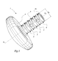
- the implant 1 shown in Figures 1 and 2 is intended to be introduced into a bore 2 formed in the external malleolus or peroneum 3.
- the implant 1 comprises a domed head 4, substantially in the form of a spherical cap and whose radius of curvature is generally equal to that of the outer cheek of the talus of the ankle considered.
- the tail 5 of the implant 1 is provided with external radial flanges 6 whose external diameter d 6 is substantially equal to the internal diameter d 2 of the bore 2.
- Two holes 7 are provided in the tail 5 and are likely to receive a suture 8 or other link flexible.
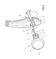
- a suture 8 or other link flexible When such a wire is engaged in one of the orifices 7, it is possible to exert on the wire 8, a tensile force T which is transmitted by wire 8 to the tail 5 as represented by the arrow T 'in FIG. 2.
- the surgeon introduces the shank 5 in hole 2 without having to exert an effort of thrust on head 4 which can be difficult to access due to the surrounding ligament system.
- the surgeon it suffices for the surgeon to place a wire in one of the orifices 7, to pass the two strands of the wire 8 through the bore 2 by the internal face of the malleolus, then to pull the strands by the external side of the malleolus.
- the traction on the wire 8 has the effect of introducing the tail 5 of the implant 1 into the bore 2 and of pressing the head 4 on the bone.
- the tensile force T exerted on the wire 8 can be intense and directed parallel to the longitudinal axis X 2 of the hole 2, so that the tail is effectively pulled towards the inside of the hole 2.
- the diameters d 2 and d 6 are substantially equal, so that the tail 5 is firmly held in position after it has been put in place.
- the tail 5 is provided with two holes 7 distributed along its axis X 5 , the hole 7 closest to the end 5a of the tail 5 being used.
- the fact that the tail 5 has several orifices 7 makes it possible to use an orifice 7 relatively close to the end 5a of the tail 5 and to have such an orifice even when the tail 5 is cut to adapt its length to the 'thickness e of the malleolus 3.
- the number of holes 7 can be increased if necessary.
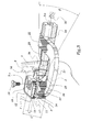
- the drilling 2 is carried out by the external face 3a of the malleolus 3 thanks to the ancillary material shown in FIGS. 3 and 4.
- This material 10 comprises a spacer block 11 intended to be placed between the tibia T and the talus A of a ankle to be fitted in implant 1.
- the block 11 comprises a substantially planar upper surface 12 intended to cooperate with a planar surface created by resection of the distal end of the tibia.
- the lower surface 13 of the block 11 is formed of two flat surfaces 13 a and 13 b inclined with respect to each other by an angle ⁇ , the surfaces 13 a and 13 b being designed to come to bear respectively on corresponding surfaces created by resection of the upper leg of the talus A.
- the surface 12 of the block 11 comprises a housing 14 in form of C intended to receive a wedge 15 whose surface upper 16 is in contact with the lower surface of the tibia T.
- the thickness E of the wedge 15 shown in the figure 3 is such that its upper surface 16 is flush with the upper surface 12 of the block 11.
- the block 11 defines a housing 17 for receiving the end 20 of a lug 21 generally in the form of C.
- the end 20 is provided with a bore, not shown, which, in the configuration of FIGS. 3 and 4, is aligned with a bore 18 formed in the block 11 and passing through this block from top to bottom, that is to say connecting the surfaces 12 and 13.
- a screw 19 can be introduced into this bore which is at least partially tapped, which allows the end 20 of the tab 21 to be immobilized inside the housing 17. In practice, the clearance provided during the tightening of the screw 19 allows limited pivoting around the axis X 18 of the bore 18.
- the lug 21 supports a clamping system 23 which can be maneuvered by means of a knob 24 and making it possible to press the malleolus 3 of the fibula P against a stop 25 formed on an extension 26 of the end 20 of lug 21.
- X 23 denotes the longitudinal axis of these clamping means.
- the clamping means 23 are hollow, so that a forest 30 can be introduced up to the level of the external face 3a of the malleolus 3 to carry out the drilling 2 from the outside towards the interior of the malleolus 3.
- the surgeon can easily target the appropriate part of the malleolus 3 thanks to the clamping means 23 which also constitute a drilling guide for the forest 30.
- the position of the X axis 23 is variable in pivoting around this X axis 18 , which makes it possible to best adjust the orientation of the bore 2 in function of the exact geometry of the malleolus 3.
- ⁇ the maximum pivot angle of the X axis 23 around the X axis 18 .
- the angle ⁇ is of the order of 10 °.
- the invention has been shown with a total prosthesis ankle, which corresponds to the geometry of the surfaces 12 and 13 of block 11. It is however applicable to a partial ankle prosthesis, without modification of implant 1, the ancillary material then being adapted to the geometry of the anatomical surfaces of articulation between the tibia and talus.
Abstract
Description
- la figure 1 est une vue en perspective d'un implant conforme à l'invention ;
- la figure 2 est une vue en perspective de l'implant de la figure 1 en cours de mise en place dans une malléole péronière représentée avec arrachement ;
- la figure 3 est une représentation schématique de principe, avec arrachements partiels, d'un matériel ancillaire de pose de l'implant de la figure 1 en cours d'utilisation et
- la figure 4 est une vue en perspective par en dessous du matériel de la figure 1.
Claims (10)
- Matériel ancillaire (10) de pose d'un implant malléolaire (1), selon l'une des revendications précédentes, caractérisé en ce qu'il comprend un bloc-entretoise (11), apte à être inséré entre le tibia (T) et l'astragale (A) d'une cheville, et une patte (21) solidaire dudit bloc-entretoise et s'étendant jusqu'au voisinage de la surface externe (3a) de la malléole péronière (3) lorsque le bloc-entretoise est en place entre le tibia et l'astragale, ladite patte supportant un guide de perçage (23) de la malléole à partir de sa surface externe.
- Matériel selon la revendication 1, caractérisé en ce que ledit bloc-entretoise (11) est pourvu d'un logement (14) de réception d'une cale (15) d'épaisseur (E) adaptée à l'écart (E') entre les surfaces inférieure du tibia (T) et supérieure de l'astragale (A).
- Matériel selon la revendication 2, caractérisé en ce que ledit logement (14) est en forme de C.
- Matériel selon l'une des revendications 2 ou 3, caractérisé en ce que ladite cale (15) vient en recouvrement d'un perçage (18) de réception d'une vis (19) d'immobilisation relative dudit bloc entretoise et de ladite patte (21).
- Matériel selon l'une des revendications 1 à 4, caractérisé en ce que ladite patte (21) est articulée (en 18) sur ledit bloc-entretoise (11) avec une possibilité de pivotement (β) limitée.
- Matériel selon la revendication 5, caractérisé en ce que ledit bloc-entretoise (11) et ladite patte (21) sont pourvus d'orifices (18) de passage d'un axe de pivotement (19) commun.
- Matériel selon l'une des revendications précédentes, caractérisé en ce que ledit guide de perçage est associé à un dispositif de serrage (23) de la malléole (3) contre une surface d'appui (25) formée sur ladite patte (21) ou ledit bloc-entretoise (11).
- Matériel selon la revendication 7, caractérisé en ce que ledit dispositif de serrage (23) est creux et forme un guide de perçage pour un forêt (30) qui peut être introduit dans ledit dispositif jusqu'au niveau de la face externe (3a) de la malléole péronière (3).
- Matériel selon l'une des revendications précédentes, caractérisé en ce que la surface inférieure (13) dudit bloc-entretoise (11) est formée de deux surfaces planes (13a, 13b) inclinées (α) l'une par rapport à l'autre.
- Implant malléolaire (1) pour prothèse partielle ou totale de cheville apte à être posé à l'aide d'un matériel ancillaire selon l'une des revendications précédentes, ledit implant comprenant une tête (4), destinée à venir en appui contre l'astragale (A) ou un composant prothétique astragalien, et une queue (5), prévue pour être introduite dans un perçage (2) du péroné (P), caractérisé en ce que ladite queue est pourvue de moyens (7) d'accrochage d'un organe de traction (8) manoeuvrable à partir du côté extérieur (3a) du péroné, pour la mise en place de ladite queue dans ledit perçage.
Applications Claiming Priority (3)
| Application Number | Priority Date | Filing Date | Title |
|---|---|---|---|
| FR9910340 | 1999-08-05 | ||
| FR9910340A FR2797178B1 (fr) | 1999-08-05 | 1999-08-05 | Implant malleolaire pour prothese partielle ou totale de cheville et materiel ancillaire de pose d'un tel implant |
| EP00420173A EP1074230B1 (fr) | 1999-08-05 | 2000-08-03 | Implant malléolaire pour prothèse partielle ou totale de cheville et matériel ancillaire de pose d'un tel implant |
Related Parent Applications (1)
| Application Number | Title | Priority Date | Filing Date |
|---|---|---|---|
| EP00420173A Division EP1074230B1 (fr) | 1999-08-05 | 2000-08-03 | Implant malléolaire pour prothèse partielle ou totale de cheville et matériel ancillaire de pose d'un tel implant |
Publications (3)
| Publication Number | Publication Date |
|---|---|
| EP1398009A2 true EP1398009A2 (fr) | 2004-03-17 |
| EP1398009A3 EP1398009A3 (fr) | 2004-10-13 |
| EP1398009B1 EP1398009B1 (fr) | 2006-11-29 |
Family
ID=9549040
Family Applications (2)
| Application Number | Title | Priority Date | Filing Date |
|---|---|---|---|
| EP00420173A Expired - Lifetime EP1074230B1 (fr) | 1999-08-05 | 2000-08-03 | Implant malléolaire pour prothèse partielle ou totale de cheville et matériel ancillaire de pose d'un tel implant |
| EP03027583A Expired - Lifetime EP1398009B1 (fr) | 1999-08-05 | 2000-08-03 | Matériel ancillaire de pose d'un implant malléolaire pour prothèse partielle ou totale de cheville et implant apte à être posé avec ce matériel |
Family Applications Before (1)
| Application Number | Title | Priority Date | Filing Date |
|---|---|---|---|
| EP00420173A Expired - Lifetime EP1074230B1 (fr) | 1999-08-05 | 2000-08-03 | Implant malléolaire pour prothèse partielle ou totale de cheville et matériel ancillaire de pose d'un tel implant |
Country Status (6)
| Country | Link |
|---|---|
| US (5) | US6488712B1 (fr) |
| EP (2) | EP1074230B1 (fr) |
| AT (2) | ATE276716T1 (fr) |
| DE (2) | DE60013982T2 (fr) |
| ES (2) | ES2275996T3 (fr) |
| FR (1) | FR2797178B1 (fr) |
Cited By (1)
| Publication number | Priority date | Publication date | Assignee | Title |
|---|---|---|---|---|
| GB2445146A (en) * | 2006-12-23 | 2008-07-02 | Corin Ltd | An Ankle Prosthesis and Resecting Jigs |
Families Citing this family (71)
| Publication number | Priority date | Publication date | Assignee | Title |
|---|---|---|---|---|
| FR2768613B1 (fr) * | 1997-09-23 | 1999-12-17 | Tornier Sa | Prothese de genou a plateau rotatoire |
| FR2797178B1 (fr) * | 1999-08-05 | 2002-02-22 | Tornier Sa | Implant malleolaire pour prothese partielle ou totale de cheville et materiel ancillaire de pose d'un tel implant |
| AU2118601A (en) * | 1999-10-22 | 2001-05-08 | Mark A. Reiley | Ankle replacement system |
| FR2826860B1 (fr) * | 2001-07-09 | 2004-03-05 | Tornier Sa | Ancillaire de pose d'un composant cubital et/ou d'un composant radial de prothese de coude |
| FR2826859B1 (fr) * | 2001-07-09 | 2003-09-19 | Tornier Sa | Ancillaire de pose d'un composant humeral de prothese de coude |
| FR2827500B1 (fr) * | 2001-07-17 | 2004-04-02 | Tornier Sa | Plaque d'osteosynthese de l'extremite superieure de l'humerus |
| US7025790B2 (en) | 2002-06-27 | 2006-04-11 | Concepts In Medicine Iii, L.L.C. | Ankle joint prosthesis and its method of implantation |
| FR2848183B1 (fr) * | 2002-12-10 | 2006-01-27 | Tornier Sa | Procede de conditionnement sterile d'un implant prothetique en polyethylene |
| FR2850010B1 (fr) * | 2003-01-17 | 2005-12-02 | Tornier Sa | Ancillaire de pose d'un cotyle prothetique pour une prothese de hanche |
| US7887544B2 (en) | 2003-03-10 | 2011-02-15 | Tornier Sas | Ancillary tool for positioning a glenoid implant |
| FR2854792B1 (fr) * | 2003-05-12 | 2005-09-09 | Tornier Sa | Jeu d'elements prothetiques pour un ensemble prothetique tibial |
| FR2855397B1 (fr) | 2003-05-28 | 2005-07-15 | Tornier Sa | Prothese de coude |
| ATE454110T1 (de) * | 2003-06-27 | 2010-01-15 | Abs Corp | System für fussgelenksarthroplastie |
| US8092547B2 (en) * | 2004-02-10 | 2012-01-10 | Tornier, Inc. | Subtalar implant assembly |
| FR2865928B1 (fr) | 2004-02-10 | 2006-03-17 | Tornier Sa | Dispositif chirurgical d'implantation d'une prothese totale de hanche |
| US7678153B2 (en) * | 2004-05-04 | 2010-03-16 | Biopro, Inc. | Subtalar implant |
| US20060041315A1 (en) * | 2004-05-04 | 2006-02-23 | Biopro, Inc. | Subtalar implant |
| US7641698B1 (en) * | 2004-06-04 | 2010-01-05 | Biomet Manufacturing Corp. | Modular hip joint implant |
| US7179259B1 (en) * | 2004-06-04 | 2007-02-20 | Biomet Manufacturing Corp. | Instrument assembly for lateral implant |
| FR2871368B1 (fr) | 2004-06-15 | 2006-08-25 | Tornier Sas | Jeu de composants humeraux pour prothese totale d'epaule |
| EP1607069B1 (fr) | 2004-06-15 | 2009-12-23 | Tornier | Prothese totale d'epaule de type inverse |
| US8303665B2 (en) | 2004-06-15 | 2012-11-06 | Tornier Sas | Glenoidal component, set of such components and shoulder prosthesis incorporating such a glenoidal component |
| US20050288792A1 (en) * | 2004-06-23 | 2005-12-29 | Landes Mark D | Modular ankle prosthesis and associated method |
| FR2872025B1 (fr) * | 2004-06-28 | 2006-08-25 | Tornier Sas | Prothese d'epaule ou de hanche |
| FR2881340B1 (fr) * | 2005-02-01 | 2008-01-11 | Tornier Sas | Clou humeral |
| EP1861047B1 (fr) | 2005-03-14 | 2017-05-31 | Inbone Acquisition Corp. | Prothese de cheville |
| FR2884407B1 (fr) * | 2005-04-13 | 2007-05-25 | Tornier Sas | Dispositif chirurgical d'implantation d'une prothese partielle ou totale du genou |
| FR2884408B1 (fr) * | 2005-04-13 | 2007-05-25 | Tornier Sas | Dispositif chirurgical d'implantation d'une prothese partielle ou totale de genou |
| US7468077B2 (en) * | 2005-08-02 | 2008-12-23 | Tornier Sas | Patellar retractor and method of surgical procedure on knee |
| FR2896404B1 (fr) * | 2006-01-24 | 2008-02-29 | Tornier Sas | Ensemble d'instrumentation chirurgicale pour poser une prothese de cheville |
| FR2896684B1 (fr) * | 2006-02-01 | 2008-09-26 | Tornier Soc Par Actions Simplifiee | Implant tibial a tige offset |
| FR2899790B1 (fr) | 2006-04-13 | 2008-06-13 | Tornier Sas | Composant glenoidien pour prothese totale d'epaule, jeu de tels composants, et prothese totale d'epaule comprenant un tel composant |
| FR2900045B1 (fr) | 2006-04-21 | 2009-01-16 | Tornier Sas | Prothese d'epaule ou de hanche |
| FR2906999B1 (fr) | 2006-10-13 | 2009-06-05 | Tornier Sas | Ensemble prothetique de cheville |
| US20100131069A1 (en) * | 2007-08-01 | 2010-05-27 | Jeffrey Halbrecht | Method and system for patella tendon realignment |
| EP2178468B1 (fr) | 2007-08-01 | 2016-06-22 | Jeffrey Halbrecht | Système pour le réalignement de ligament rotulien |
| US20090105840A1 (en) * | 2007-10-18 | 2009-04-23 | Inbone Technologies, Inc. | Fibular stiffener and bony defect replacer |
| US8052755B2 (en) * | 2008-05-09 | 2011-11-08 | Remi Sciences, Inc. | Ulnar head prosthesis system |
| EP2656797A3 (fr) | 2008-07-17 | 2014-02-12 | Smith & Nephew, Inc. | Ancrage |
| US10327817B2 (en) | 2008-08-01 | 2019-06-25 | Skeletal Dynamics Llc | Internal joint stabilizer device, system and method of use |
| JP5656833B2 (ja) * | 2008-08-01 | 2015-01-21 | スケルタル ダイナミクス エルエルシー | 内部関節安定化装置、内部関節安定化システムおよびその使用方法 |
| US8808303B2 (en) | 2009-02-24 | 2014-08-19 | Microport Orthopedics Holdings Inc. | Orthopedic surgical guide |
| US8808297B2 (en) | 2009-02-24 | 2014-08-19 | Microport Orthopedics Holdings Inc. | Orthopedic surgical guide |
| US9017334B2 (en) | 2009-02-24 | 2015-04-28 | Microport Orthopedics Holdings Inc. | Patient specific surgical guide locator and mount |
| US8597362B2 (en) | 2009-08-27 | 2013-12-03 | Cotera, Inc. | Method and apparatus for force redistribution in articular joints |
| US9668868B2 (en) | 2009-08-27 | 2017-06-06 | Cotera, Inc. | Apparatus and methods for treatment of patellofemoral conditions |
| US9861408B2 (en) | 2009-08-27 | 2018-01-09 | The Foundry, Llc | Method and apparatus for treating canine cruciate ligament disease |
| US9278004B2 (en) | 2009-08-27 | 2016-03-08 | Cotera, Inc. | Method and apparatus for altering biomechanics of the articular joints |
| US10349980B2 (en) | 2009-08-27 | 2019-07-16 | The Foundry, Llc | Method and apparatus for altering biomechanics of the shoulder |
| US8647391B2 (en) | 2010-07-07 | 2014-02-11 | Global Orthopaedic Solutions Llc | Malleolar replacement devices |
| FR2966343B1 (fr) | 2010-10-22 | 2012-12-07 | Tornier Sa | Jeu de composants glenoidiens d'une prothese d'epaule |
| AU2016244327B2 (en) * | 2010-12-20 | 2018-04-05 | Microport Orthopedics Holdings Inc. | Orthopedic surgical guide |
| US8979937B2 (en) | 2011-09-27 | 2015-03-17 | Linares Medical Devices, Llc | Implantable ankle joint assembly with spherical inter-support |
| US9468466B1 (en) | 2012-08-24 | 2016-10-18 | Cotera, Inc. | Method and apparatus for altering biomechanics of the spine |
| US9974588B2 (en) | 2012-12-27 | 2018-05-22 | Wright Medical Technology, Inc. | Ankle replacement system and method |
| US10080573B2 (en) | 2012-12-27 | 2018-09-25 | Wright Medical Technology, Inc. | Ankle replacement system and method |
| CA2836651C (fr) | 2012-12-27 | 2016-03-22 | Wright Medical Technology, Inc. | Systeme de prothese de cheville et methode |
| US9480571B2 (en) | 2012-12-27 | 2016-11-01 | Wright Medical Technology, Inc. | Ankle replacement system and method |
| US9918724B2 (en) | 2012-12-27 | 2018-03-20 | Wright Medical Technology, Inc. | Ankle replacement system and method |
| JP6382237B2 (ja) | 2013-03-06 | 2018-08-29 | スミス アンド ネフュー インコーポレーテッドSmith & Nephew,Inc. | マイクロアンカー |
| US9949839B2 (en) | 2013-03-13 | 2018-04-24 | Wright Medical Technology, Inc. | Revision implant augments, systems, and methods |
| CN105228541A (zh) | 2013-03-14 | 2016-01-06 | 瑞特医疗技术公司 | 踝部替换系统与方法 |
| AU2015259293B2 (en) | 2014-05-12 | 2019-07-11 | Smith & Nephew Asia Pacific Pte. Limited | Total ankle replacement prosthesis |
| US10575968B2 (en) | 2014-05-16 | 2020-03-03 | Howmedica Osteonics Corp. | Guides for fracture system |
| US9681960B2 (en) | 2014-05-16 | 2017-06-20 | Howmedica Osteonics Corp. | Guides for fracture system |
| US20150374503A1 (en) * | 2014-06-30 | 2015-12-31 | Bacterin International, Inc. | Implant for fusion between adjacent bone bodies |
| CN105726135B (zh) * | 2016-01-28 | 2018-10-26 | 佛山市乙太医疗用品有限公司 | 一种应用于临床手术中的肘关节旋转中心导向器 |
| JP2019509132A (ja) | 2016-03-23 | 2019-04-04 | ライト メディカル テクノロジー インコーポレイテッドWright Medical Technology, Inc. | 人工足関節全置換術のための固定装置及び方法 |
| US10136998B2 (en) | 2016-08-30 | 2018-11-27 | Wright Medical Technology, Inc. | Revision total ankle implants |
| WO2021138081A1 (fr) | 2020-01-02 | 2021-07-08 | Zkr Orthopedics, Inc. | Implant de réalignement de tendon de rotule ayant une forme modifiable |
| US11872137B2 (en) | 2021-06-15 | 2024-01-16 | Wright Medical Technology, Inc. | Unicompartmental ankle prosthesis |
Citations (4)
| Publication number | Priority date | Publication date | Assignee | Title |
|---|---|---|---|---|
| US4159716A (en) * | 1977-10-17 | 1979-07-03 | Borchers Clinton H | Method of compressing and realigning bone structures to correct splay foot |
| US4235428A (en) * | 1979-03-15 | 1980-11-25 | Davis Jack H | Bone transfixation pin guide |
| FR2700462A1 (fr) * | 1993-01-19 | 1994-07-22 | Medimplant | Appareillage d'implantation d'une prothèse articulaire. |
| US5601550A (en) * | 1994-10-25 | 1997-02-11 | Esser; Rene D. | Pelvic pin guide system for insertion of pins into iliac bone |
Family Cites Families (85)
| Publication number | Priority date | Publication date | Assignee | Title |
|---|---|---|---|---|
| US2393831A (en) * | 1942-12-29 | 1946-01-29 | Stader Otto | Bone splint |
| US3779654A (en) * | 1971-08-06 | 1973-12-18 | R Horne | Artificial joint |
| US3987500A (en) * | 1976-01-28 | 1976-10-26 | Schlein Allen P | Surgically implantable total ankle prosthesis |
| US4069518A (en) * | 1976-08-31 | 1978-01-24 | Groth Jr Harry E | Total ankle prosthesis |
| GB1579773A (en) * | 1977-07-18 | 1980-11-26 | Nat Res Dev | Endoprosthetic bone joint devices |
| US4257411A (en) * | 1979-02-08 | 1981-03-24 | Cho Kenneth O | Cruciate ligament surgical drill guide |
| US4644943A (en) * | 1984-07-20 | 1987-02-24 | Regents Of The University Of Minnesota | Bone fixation device |
| US4722331A (en) * | 1985-09-03 | 1988-02-02 | Fox James M | Orthopaedic tool guide |
| IT1221530B (it) * | 1987-07-20 | 1990-07-12 | Italpres Snc Di Fregni Bruno & | Attrezzatura per la perforazione di precisione del femore e della tibia per l'installazione della articolazione del ginocchio dei legamenti protesici anteriore e posteriore crociati |
| US5197986A (en) * | 1990-04-11 | 1993-03-30 | Mikhail Michael W E | Recessed patellar prosthesis |
| US5236445A (en) * | 1990-07-02 | 1993-08-17 | American Cyanamid Company | Expandable bone anchor and method of anchoring a suture to a bone |
| US5258016A (en) * | 1990-07-13 | 1993-11-02 | American Cyanamid Company | Suture anchor and driver assembly |
| FR2669213A1 (fr) * | 1990-11-19 | 1992-05-22 | Tornier Sa | Prothese femorale partiellement cimentee. |
| US5354298A (en) * | 1991-03-22 | 1994-10-11 | United States Surgical Corporation | Suture anchor installation system |
| US5480403A (en) * | 1991-03-22 | 1996-01-02 | United States Surgical Corporation | Suture anchoring device and method |
| FR2681240A1 (fr) * | 1991-09-12 | 1993-03-19 | Tornier Sa | Prothese totale de poignet. |
| FR2684290B1 (fr) * | 1991-11-29 | 1994-01-21 | Tornier Ets | Prothese du genou. |
| FR2685633B1 (fr) * | 1991-12-27 | 1998-02-27 | Tornier Sa | Prothese humerale modulaire. |
| FR2691357A1 (fr) * | 1992-05-25 | 1993-11-26 | Tornier Sa | Prothèse totale pour l'articulation métacarpo-phalangienne. |
| US5312409A (en) * | 1992-06-01 | 1994-05-17 | Mclaughlin Robert E | Drill alignment guide |
| US5176682A (en) * | 1992-06-01 | 1993-01-05 | Chow James C Y | Surgical implement |
| US5306290A (en) * | 1993-02-12 | 1994-04-26 | Mitek Surgical Products, Inc. | Suture button |
| US5380334A (en) * | 1993-02-17 | 1995-01-10 | Smith & Nephew Dyonics, Inc. | Soft tissue anchors and systems for implantation |
| FR2703240B1 (fr) * | 1993-03-30 | 1995-06-02 | Tornier Sa | Prothèse cotyloïdienne élastiquement déformable. |
| FR2705226B1 (fr) * | 1993-05-17 | 1995-07-07 | Tornier Sa | Fixateur de rachis pour le maintien d'une colonne vertébrale. |
| US5423860A (en) * | 1993-05-28 | 1995-06-13 | American Cyanamid Company | Protective carrier for suture anchor |
| FR2709412B1 (fr) * | 1993-09-01 | 1995-11-24 | Tornier Sa | Vis pour fixateur lombo-sacré. |
| FR2711505B1 (fr) * | 1993-10-25 | 1995-12-29 | Tornier Sa | Dispositif de synthèse des fractures de l'extrémité supérieure du fémur. |
| US5403321A (en) * | 1993-12-15 | 1995-04-04 | Smith & Nephew Richards Inc. | Radiolucent drill guide |
| US5486197A (en) * | 1994-03-24 | 1996-01-23 | Ethicon, Inc. | Two-piece suture anchor with barbs |
| FR2724553B1 (fr) * | 1994-09-15 | 1996-12-20 | Tornier Sa | Fixateur externe ou interne destine a la reparation des fractures ou des arthroplasties du squelette |
| US5464427A (en) * | 1994-10-04 | 1995-11-07 | Synthes (U.S.A.) | Expanding suture anchor |
| FR2727002B1 (fr) * | 1994-11-18 | 1997-01-03 | Tornier Sa | Prothese humerale a sphere |
| US5674224A (en) * | 1994-11-18 | 1997-10-07 | Howell; Stephen M. | Bone mulch screw assembly for endosteal fixation of soft tissue grafts and method for using same |
| FR2728159B1 (fr) * | 1994-12-16 | 1997-06-27 | Tornier Sa | Prothese discale elastique |
| US5766259A (en) * | 1995-03-14 | 1998-06-16 | Sammarco; Giacomo J. | Total ankle prosthesis and method |
| FR2735356B1 (fr) * | 1995-06-16 | 1997-11-28 | Tornier Sa | Implant cotyloidien destine notamment a la cavite articulaire iliaque |
| FR2741796B1 (fr) * | 1995-11-30 | 1998-03-27 | Tornier Sa | Dispositif pour la fixation d'une prothese et notamment d'une prothese glenoidienne de l'omoplate |
| FR2743716B1 (fr) * | 1996-01-23 | 1998-04-10 | Tornier Sa | Prothese tibiale |
| FR2747302B1 (fr) * | 1996-04-11 | 1998-09-11 | Tornier Sa | Prothese de cheville |
| FR2750037B1 (fr) * | 1996-06-25 | 1998-11-27 | Tornier Sa | Prothese d'epaule monobloc |
| FR2751868B1 (fr) * | 1996-08-02 | 1999-04-16 | Tornier Sa | Prothese ajouree de l'extremite superieure de l'humerus |
| EP1419747B1 (fr) * | 1996-11-21 | 2015-04-01 | Ethicon, Inc. | Appareil d'ancrage de greffes autologues ou artificielles de tendon dans l'os |
| FR2758455B1 (fr) * | 1997-01-23 | 1999-08-06 | Tornier Sa | Prothese totale de coude |
| FR2760353B1 (fr) * | 1997-03-10 | 1999-07-02 | Tornier Sa | Prothese de cheville |
| FR2760354B1 (fr) | 1997-03-10 | 1999-07-02 | Tornier Sa | Prothese partielle de cheville |
| FR2768330B1 (fr) * | 1997-09-12 | 2000-01-21 | Tornier Sa | Prothese humeral a sphere indexee |
| FR2768613B1 (fr) * | 1997-09-23 | 1999-12-17 | Tornier Sa | Prothese de genou a plateau rotatoire |
| FR2768922B1 (fr) * | 1997-10-01 | 2000-01-14 | Tornier Sa | Prothese destinee a etre ancree dans un os long |
| FR2769494B1 (fr) * | 1997-10-14 | 1999-12-31 | Michel Timoteo | Piece femorale pour prothese de genou |
| FR2769495B1 (fr) * | 1997-10-14 | 1999-12-31 | Michel Timoteo | Prothese de genou |
| US5931837A (en) * | 1997-12-09 | 1999-08-03 | University Of Iowa Research Foundation | Method and apparatus for external fixation of an ankle |
| FR2772259B1 (fr) * | 1997-12-12 | 2000-03-03 | Tornier Sa | Perfectionnements apportes aux protheses totales de genou comportant un element femoral et un plateau tibial |
| FR2775586B1 (fr) * | 1998-03-03 | 2000-06-30 | Tornier Sa | Implant acetabulaire ou cotyloidien modulaire |
| FR2777447B1 (fr) * | 1998-04-21 | 2000-07-28 | Tornier Sa | Dispositif de fixation reversible pour la mise en place d'un implant dans l'os |
| FR2777443B1 (fr) * | 1998-04-21 | 2000-06-30 | Tornier Sa | Ancillaire pour la mise en place et le retrait d'un implant et plus particulierement d'une ancre de suture |
| FR2777442B1 (fr) * | 1998-04-21 | 2000-07-28 | Tornier Sa | Ancre de suture a expansion reversible |
| FR2782913B1 (fr) * | 1998-09-04 | 2000-11-10 | Perice Ramon Viladot | Implant pour pied plat |
| US6086591A (en) * | 1999-01-29 | 2000-07-11 | Smith & Nephew, Inc. | Soft tissue anchor |
| FR2793404B1 (fr) * | 1999-05-14 | 2001-09-14 | Tornier Sa | Prothese de coude |
| FR2794641B1 (fr) * | 1999-06-09 | 2001-11-23 | Tornier Sa | Prothese humerale |
| FR2797178B1 (fr) * | 1999-08-05 | 2002-02-22 | Tornier Sa | Implant malleolaire pour prothese partielle ou totale de cheville et materiel ancillaire de pose d'un tel implant |
| FR2826859B1 (fr) * | 2001-07-09 | 2003-09-19 | Tornier Sa | Ancillaire de pose d'un composant humeral de prothese de coude |
| FR2826860B1 (fr) * | 2001-07-09 | 2004-03-05 | Tornier Sa | Ancillaire de pose d'un composant cubital et/ou d'un composant radial de prothese de coude |
| FR2827500B1 (fr) * | 2001-07-17 | 2004-04-02 | Tornier Sa | Plaque d'osteosynthese de l'extremite superieure de l'humerus |
| FR2831426B1 (fr) * | 2001-10-30 | 2004-07-16 | Tornier Sa | Implant rotulien et prothese de genou incorporant un tel implant |
| US6685706B2 (en) * | 2001-11-19 | 2004-02-03 | Triage Medical, Inc. | Proximal anchors for bone fixation system |
| FR2835425B1 (fr) * | 2002-02-04 | 2004-04-09 | Tornier Sa | Element prothetique comprenant deux composants et procede d'assemblage d'un tel element prothetique |
| FR2836039B1 (fr) * | 2002-02-15 | 2004-10-01 | Tornier Sa | Composant glenoidien de prothese d'epaule et prothese totale d'epaule incorporant un tel composant |
| FR2841768B1 (fr) * | 2002-07-05 | 2005-05-06 | Tornier Sa | Prothese d'epaule ou de hanche facilitant l'abduction |
| FR2848183B1 (fr) * | 2002-12-10 | 2006-01-27 | Tornier Sa | Procede de conditionnement sterile d'un implant prothetique en polyethylene |
| FR2850010B1 (fr) * | 2003-01-17 | 2005-12-02 | Tornier Sa | Ancillaire de pose d'un cotyle prothetique pour une prothese de hanche |
| US7887544B2 (en) * | 2003-03-10 | 2011-02-15 | Tornier Sas | Ancillary tool for positioning a glenoid implant |
| FR2854792B1 (fr) * | 2003-05-12 | 2005-09-09 | Tornier Sa | Jeu d'elements prothetiques pour un ensemble prothetique tibial |
| FR2855397B1 (fr) * | 2003-05-28 | 2005-07-15 | Tornier Sa | Prothese de coude |
| FR2859099B1 (fr) * | 2003-08-25 | 2006-01-06 | Tornier Sa | Composant glenoidien de prothese d'epaule et prothese totale d'epaule incorporant un tel composant |
| FR2863865B1 (fr) * | 2003-12-19 | 2006-10-06 | Tornier Sa | Prothese d'epaule ou de hanche et son procede de montage |
| FR2865928B1 (fr) * | 2004-02-10 | 2006-03-17 | Tornier Sa | Dispositif chirurgical d'implantation d'une prothese totale de hanche |
| US8303665B2 (en) | 2004-06-15 | 2012-11-06 | Tornier Sas | Glenoidal component, set of such components and shoulder prosthesis incorporating such a glenoidal component |
| FR2871368B1 (fr) | 2004-06-15 | 2006-08-25 | Tornier Sas | Jeu de composants humeraux pour prothese totale d'epaule |
| FR2871371B1 (fr) | 2004-06-15 | 2007-04-06 | Tornier Sas | Composant glenoidien de prothese d'epaule, jeu d'elements constitutifs d'un tel composant et prothese totale d'epaule incorporant un tel composant |
| EP1607069B1 (fr) | 2004-06-15 | 2009-12-23 | Tornier | Prothese totale d'epaule de type inverse |
| FR2872025B1 (fr) | 2004-06-28 | 2006-08-25 | Tornier Sas | Prothese d'epaule ou de hanche |
| FR2881340B1 (fr) | 2005-02-01 | 2008-01-11 | Tornier Sas | Clou humeral |
| FR2884408B1 (fr) | 2005-04-13 | 2007-05-25 | Tornier Sas | Dispositif chirurgical d'implantation d'une prothese partielle ou totale de genou |
-
1999
- 1999-08-05 FR FR9910340A patent/FR2797178B1/fr not_active Expired - Fee Related
-
2000
- 2000-08-03 ES ES03027583T patent/ES2275996T3/es not_active Expired - Lifetime
- 2000-08-03 US US09/631,938 patent/US6488712B1/en not_active Expired - Lifetime
- 2000-08-03 ES ES00420173T patent/ES2226750T3/es not_active Expired - Lifetime
- 2000-08-03 AT AT00420173T patent/ATE276716T1/de not_active IP Right Cessation
- 2000-08-03 DE DE60013982T patent/DE60013982T2/de not_active Expired - Lifetime
- 2000-08-03 EP EP00420173A patent/EP1074230B1/fr not_active Expired - Lifetime
- 2000-08-03 AT AT03027583T patent/ATE346573T1/de not_active IP Right Cessation
- 2000-08-03 DE DE60032188T patent/DE60032188T2/de not_active Expired - Lifetime
- 2000-08-03 EP EP03027583A patent/EP1398009B1/fr not_active Expired - Lifetime
-
2002
- 2002-09-26 US US10/254,984 patent/US7476227B2/en not_active Expired - Lifetime
- 2002-09-26 US US10/254,985 patent/US6824567B2/en not_active Expired - Lifetime
-
2007
- 2007-02-23 US US11/678,424 patent/US20070162025A1/en not_active Abandoned
-
2008
- 2008-10-27 US US12/258,904 patent/US7993346B2/en not_active Expired - Fee Related
Patent Citations (4)
| Publication number | Priority date | Publication date | Assignee | Title |
|---|---|---|---|---|
| US4159716A (en) * | 1977-10-17 | 1979-07-03 | Borchers Clinton H | Method of compressing and realigning bone structures to correct splay foot |
| US4235428A (en) * | 1979-03-15 | 1980-11-25 | Davis Jack H | Bone transfixation pin guide |
| FR2700462A1 (fr) * | 1993-01-19 | 1994-07-22 | Medimplant | Appareillage d'implantation d'une prothèse articulaire. |
| US5601550A (en) * | 1994-10-25 | 1997-02-11 | Esser; Rene D. | Pelvic pin guide system for insertion of pins into iliac bone |
Cited By (2)
| Publication number | Priority date | Publication date | Assignee | Title |
|---|---|---|---|---|
| GB2445146A (en) * | 2006-12-23 | 2008-07-02 | Corin Ltd | An Ankle Prosthesis and Resecting Jigs |
| GB2445146B (en) * | 2006-12-23 | 2011-10-05 | Corin Ltd | Improvements in and relating to an ankle prosthesis |
Also Published As
| Publication number | Publication date |
|---|---|
| ATE346573T1 (de) | 2006-12-15 |
| US20090048687A1 (en) | 2009-02-19 |
| US20030023315A1 (en) | 2003-01-30 |
| DE60013982T2 (de) | 2006-03-09 |
| EP1398009A3 (fr) | 2004-10-13 |
| US20030028198A1 (en) | 2003-02-06 |
| DE60013982D1 (de) | 2004-10-28 |
| US7476227B2 (en) | 2009-01-13 |
| ES2226750T3 (es) | 2005-04-01 |
| US6824567B2 (en) | 2004-11-30 |
| ATE276716T1 (de) | 2004-10-15 |
| DE60032188T2 (de) | 2007-09-27 |
| ES2275996T3 (es) | 2007-06-16 |
| FR2797178B1 (fr) | 2002-02-22 |
| US6488712B1 (en) | 2002-12-03 |
| EP1074230A1 (fr) | 2001-02-07 |
| EP1074230B1 (fr) | 2004-09-22 |
| US20070162025A1 (en) | 2007-07-12 |
| EP1398009B1 (fr) | 2006-11-29 |
| US7993346B2 (en) | 2011-08-09 |
| DE60032188D1 (de) | 2007-01-11 |
| FR2797178A1 (fr) | 2001-02-09 |
Similar Documents
| Publication | Publication Date | Title |
|---|---|---|
| EP1398009B1 (fr) | Matériel ancillaire de pose d'un implant malléolaire pour prothèse partielle ou totale de cheville et implant apte à être posé avec ce matériel | |
| EP1011504B1 (fr) | Instrumentation d'osteosynthese a connecteur entre tige vertebrale et organes d'ancrage | |
| EP1978894B1 (fr) | Implant chirurgical a appui extra cortical pour transplant ligamentaire | |
| EP0392927B1 (fr) | Implant vertébral pour dispositif d'ostéosynthèse | |
| EP0756472B1 (fr) | Dispositif de stabilisation d'ancrage orthopedique | |
| EP0755658A1 (fr) | Dispositif pour la réduction et maintien des fractures osseuses | |
| FR2658414A1 (fr) | Implant pour dispositif d'osteosynthese en particulier du rachis. | |
| CA2330802A1 (fr) | Systeme d'osteosynthese rachidienne avec moyens de serrage notamment pour une fixation anterieure | |
| FR2810532A1 (fr) | Implant osseux a moyens de blocage annulaires | |
| FR2784282A1 (fr) | Systeme d'osteosynthese rachidienne a rigidite amelioree | |
| FR2846870A1 (fr) | Materiel d'osteosynthese pour le traitement d'un cubitus"long" | |
| FR2827758A1 (fr) | Ancillaire pour systeme d'ostheosynthese rachidienne | |
| FR2556583A1 (fr) | Plaques d'osteosynthese pour derotation osseuse, en particulier derotation femorale | |
| WO1996036291A1 (fr) | Dispositif d'osteosynthese implantable | |
| EP2667796A1 (fr) | Dispositif de forage pour la réalisation d'un canal osseux à profil courbe à l'intérieur du corps d'une vertèbre | |
| EP0317406A1 (fr) | Cheville artificielle par la fixation intra-osseuse de prothèses ligamentaires et renforts ligamentaires, ainsi que l'impacteur associé comportant des moyens de maintien de ladite cheville | |
| FR2680461A1 (fr) | Implant pour dispositif d'osteosynthese notamment du rachis et dispositif correspondant pour sa mise en place. | |
| CA2306418A1 (fr) | Dispositif de fixation d'une tige dans une paroi osseuse mince | |
| FR2790941A1 (fr) | Instrumentation d'osteosynthese rachidienne a plaque et vis pediculaire ou a connecteur transversal entre une tige vertebrale et une vis pediculaire | |
| WO2001056507A1 (fr) | Dispositif de fixation d'un implant ou d'un transplant formant ligament prothetique sur un os | |
| FR2796829A1 (fr) | Plaque d'osteotomie tibiale | |
| FR2656212A1 (fr) | Systeme d'enclouage centro-medullaire pour immobiliser une fracture d'un os. | |
| EP1361827B1 (fr) | Vis de fixation | |
| EP1703853B1 (fr) | Implant dentaire | |
| FR2895664A1 (fr) | Vis transcalcaneum pour arthrodese de la cheville |
Legal Events
| Date | Code | Title | Description |
|---|---|---|---|
| PUAI | Public reference made under article 153(3) epc to a published international application that has entered the european phase |
Free format text: ORIGINAL CODE: 0009012 |
|
| 17P | Request for examination filed |
Effective date: 20031201 |
|
| AC | Divisional application: reference to earlier application |
Ref document number: 1074230 Country of ref document: EP Kind code of ref document: P |
|
| AK | Designated contracting states |
Kind code of ref document: A2 Designated state(s): AT BE CH CY DE DK ES FI FR GB GR IE IT LI LU MC NL PT SE |
|
| RIN1 | Information on inventor provided before grant (corrected) |
Inventor name: BONNIN, MICHEL Inventor name: COLOMBIER, JEAN-ALAIN Inventor name: JUDET, THIERRY Inventor name: TORNIER, ALAIN |
|
| RIC1 | Information provided on ipc code assigned before grant |
Ipc: 7A 61F 2/42 A Ipc: 7A 61B 17/17 B Ipc: 7A 61F 2/46 B |
|
| PUAL | Search report despatched |
Free format text: ORIGINAL CODE: 0009013 |
|
| AK | Designated contracting states |
Kind code of ref document: A3 Designated state(s): AT BE CH CY DE DK ES FI FR GB GR IE IT LI LU MC NL PT SE |
|
| AKX | Designation fees paid |
Designated state(s): AT BE CH CY DE DK ES FI FR GB GR IE IT LI LU MC NL PT SE |
|
| GRAP | Despatch of communication of intention to grant a patent |
Free format text: ORIGINAL CODE: EPIDOSNIGR1 |
|
| GRAS | Grant fee paid |
Free format text: ORIGINAL CODE: EPIDOSNIGR3 |
|
| GRAA | (expected) grant |
Free format text: ORIGINAL CODE: 0009210 |
|
| AC | Divisional application: reference to earlier application |
Ref document number: 1074230 Country of ref document: EP Kind code of ref document: P |
|
| AK | Designated contracting states |
Kind code of ref document: B1 Designated state(s): AT BE CH CY DE DK ES FI FR GB GR IE IT LI LU MC NL PT SE |
|
| PG25 | Lapsed in a contracting state [announced via postgrant information from national office to epo] |
Ref country code: FI Free format text: LAPSE BECAUSE OF FAILURE TO SUBMIT A TRANSLATION OF THE DESCRIPTION OR TO PAY THE FEE WITHIN THE PRESCRIBED TIME-LIMIT Effective date: 20061129 Ref country code: NL Free format text: LAPSE BECAUSE OF FAILURE TO SUBMIT A TRANSLATION OF THE DESCRIPTION OR TO PAY THE FEE WITHIN THE PRESCRIBED TIME-LIMIT Effective date: 20061129 Ref country code: AT Free format text: LAPSE BECAUSE OF FAILURE TO SUBMIT A TRANSLATION OF THE DESCRIPTION OR TO PAY THE FEE WITHIN THE PRESCRIBED TIME-LIMIT Effective date: 20061129 |
|
| REG | Reference to a national code |
Ref country code: GB Ref legal event code: FG4D Free format text: NOT ENGLISH |
|
| REG | Reference to a national code |
Ref country code: CH Ref legal event code: EP |
|
| REG | Reference to a national code |
Ref country code: IE Ref legal event code: FG4D Free format text: LANGUAGE OF EP DOCUMENT: FRENCH |
|
| REF | Corresponds to: |
Ref document number: 60032188 Country of ref document: DE Date of ref document: 20070111 Kind code of ref document: P |
|
| GBT | Gb: translation of ep patent filed (gb section 77(6)(a)/1977) |
Effective date: 20070110 |
|
| PG25 | Lapsed in a contracting state [announced via postgrant information from national office to epo] |
Ref country code: SE Free format text: LAPSE BECAUSE OF FAILURE TO SUBMIT A TRANSLATION OF THE DESCRIPTION OR TO PAY THE FEE WITHIN THE PRESCRIBED TIME-LIMIT Effective date: 20070228 Ref country code: DK Free format text: LAPSE BECAUSE OF FAILURE TO SUBMIT A TRANSLATION OF THE DESCRIPTION OR TO PAY THE FEE WITHIN THE PRESCRIBED TIME-LIMIT Effective date: 20070228 |
|
| PG25 | Lapsed in a contracting state [announced via postgrant information from national office to epo] |
Ref country code: PT Free format text: LAPSE BECAUSE OF FAILURE TO SUBMIT A TRANSLATION OF THE DESCRIPTION OR TO PAY THE FEE WITHIN THE PRESCRIBED TIME-LIMIT Effective date: 20070430 |
|
| NLV1 | Nl: lapsed or annulled due to failure to fulfill the requirements of art. 29p and 29m of the patents act | ||
| REG | Reference to a national code |
Ref country code: ES Ref legal event code: FG2A Ref document number: 2275996 Country of ref document: ES Kind code of ref document: T3 |
|
| PLBE | No opposition filed within time limit |
Free format text: ORIGINAL CODE: 0009261 |
|
| STAA | Information on the status of an ep patent application or granted ep patent |
Free format text: STATUS: NO OPPOSITION FILED WITHIN TIME LIMIT |
|
| 26N | No opposition filed |
Effective date: 20070830 |
|
| BERE | Be: lapsed |
Owner name: TORNIER Effective date: 20070831 |
|
| PG25 | Lapsed in a contracting state [announced via postgrant information from national office to epo] |
Ref country code: MC Free format text: LAPSE BECAUSE OF NON-PAYMENT OF DUE FEES Effective date: 20070831 Ref country code: GR Free format text: LAPSE BECAUSE OF FAILURE TO SUBMIT A TRANSLATION OF THE DESCRIPTION OR TO PAY THE FEE WITHIN THE PRESCRIBED TIME-LIMIT Effective date: 20070301 |
|
| PG25 | Lapsed in a contracting state [announced via postgrant information from national office to epo] |
Ref country code: BE Free format text: LAPSE BECAUSE OF NON-PAYMENT OF DUE FEES Effective date: 20070831 |
|
| PG25 | Lapsed in a contracting state [announced via postgrant information from national office to epo] |
Ref country code: LU Free format text: LAPSE BECAUSE OF NON-PAYMENT OF DUE FEES Effective date: 20070803 Ref country code: CY Free format text: LAPSE BECAUSE OF FAILURE TO SUBMIT A TRANSLATION OF THE DESCRIPTION OR TO PAY THE FEE WITHIN THE PRESCRIBED TIME-LIMIT Effective date: 20061129 |
|
| PGFP | Annual fee paid to national office [announced via postgrant information from national office to epo] |
Ref country code: CH Payment date: 20100812 Year of fee payment: 11 Ref country code: ES Payment date: 20100825 Year of fee payment: 11 Ref country code: IE Payment date: 20100727 Year of fee payment: 11 |
|
| PGFP | Annual fee paid to national office [announced via postgrant information from national office to epo] |
Ref country code: IT Payment date: 20100826 Year of fee payment: 11 |
|
| PGFP | Annual fee paid to national office [announced via postgrant information from national office to epo] |
Ref country code: GB Payment date: 20100721 Year of fee payment: 11 |
|
| REG | Reference to a national code |
Ref country code: CH Ref legal event code: PL |
|
| GBPC | Gb: european patent ceased through non-payment of renewal fee |
Effective date: 20110803 |
|
| PG25 | Lapsed in a contracting state [announced via postgrant information from national office to epo] |
Ref country code: CH Free format text: LAPSE BECAUSE OF NON-PAYMENT OF DUE FEES Effective date: 20110831 Ref country code: LI Free format text: LAPSE BECAUSE OF NON-PAYMENT OF DUE FEES Effective date: 20110831 |
|
| REG | Reference to a national code |
Ref country code: IE Ref legal event code: MM4A |
|
| PG25 | Lapsed in a contracting state [announced via postgrant information from national office to epo] |
Ref country code: IT Free format text: LAPSE BECAUSE OF NON-PAYMENT OF DUE FEES Effective date: 20110803 |
|
| PG25 | Lapsed in a contracting state [announced via postgrant information from national office to epo] |
Ref country code: IE Free format text: LAPSE BECAUSE OF NON-PAYMENT OF DUE FEES Effective date: 20110803 |
|
| PG25 | Lapsed in a contracting state [announced via postgrant information from national office to epo] |
Ref country code: GB Free format text: LAPSE BECAUSE OF NON-PAYMENT OF DUE FEES Effective date: 20110803 |
|
| REG | Reference to a national code |
Ref country code: DE Ref legal event code: R082 Ref document number: 60032188 Country of ref document: DE Representative=s name: DR. MUELLER PATENTANWAELTE, DE |
|
| PGFP | Annual fee paid to national office [announced via postgrant information from national office to epo] |
Ref country code: FR Payment date: 20120824 Year of fee payment: 13 Ref country code: DE Payment date: 20120808 Year of fee payment: 13 |
|
| REG | Reference to a national code |
Ref country code: FR Ref legal event code: CA Effective date: 20121213 |
|
| REG | Reference to a national code |
Ref country code: DE Ref legal event code: R082 Ref document number: 60032188 Country of ref document: DE Representative=s name: DR. MUELLER PATENTANWAELTE, DE Effective date: 20121126 Ref country code: DE Ref legal event code: R081 Ref document number: 60032188 Country of ref document: DE Owner name: TORNIER, FR Free format text: FORMER OWNER: TORNIER, SAINT-ISMIER, FR Effective date: 20121126 |
|
| REG | Reference to a national code |
Ref country code: ES Ref legal event code: FD2A Effective date: 20130531 |
|
| REG | Reference to a national code |
Ref country code: FR Ref legal event code: GC Effective date: 20130515 |
|
| PG25 | Lapsed in a contracting state [announced via postgrant information from national office to epo] |
Ref country code: ES Free format text: LAPSE BECAUSE OF NON-PAYMENT OF DUE FEES Effective date: 20110804 |
|
| PG25 | Lapsed in a contracting state [announced via postgrant information from national office to epo] |
Ref country code: DE Free format text: LAPSE BECAUSE OF NON-PAYMENT OF DUE FEES Effective date: 20140301 |
|
| REG | Reference to a national code |
Ref country code: DE Ref legal event code: R119 Ref document number: 60032188 Country of ref document: DE Effective date: 20140301 |
|
| REG | Reference to a national code |
Ref country code: FR Ref legal event code: ST Effective date: 20140430 |
|
| PG25 | Lapsed in a contracting state [announced via postgrant information from national office to epo] |
Ref country code: FR Free format text: LAPSE BECAUSE OF NON-PAYMENT OF DUE FEES Effective date: 20130902 |
|
| REG | Reference to a national code |
Ref country code: FR Ref legal event code: RG Effective date: 20160128 |