EP1399694B1 - Led luminaire with light sensor configurations for optical feedback - Google Patents
Led luminaire with light sensor configurations for optical feedback Download PDFInfo
- Publication number
- EP1399694B1 EP1399694B1 EP02735758A EP02735758A EP1399694B1 EP 1399694 B1 EP1399694 B1 EP 1399694B1 EP 02735758 A EP02735758 A EP 02735758A EP 02735758 A EP02735758 A EP 02735758A EP 1399694 B1 EP1399694 B1 EP 1399694B1
- Authority
- EP
- European Patent Office
- Prior art keywords
- led
- color
- light output
- light
- array
- Prior art date
- Legal status (The legal status is an assumption and is not a legal conclusion. Google has not performed a legal analysis and makes no representation as to the accuracy of the status listed.)
- Expired - Lifetime
Links
- 230000003287 optical effect Effects 0.000 title description 14
- 239000003086 colorant Substances 0.000 claims abstract description 6
- 238000001914 filtration Methods 0.000 claims 1
- 239000000758 substrate Substances 0.000 description 4
- 230000000712 assembly Effects 0.000 description 3
- 238000000429 assembly Methods 0.000 description 3
- 239000011248 coating agent Substances 0.000 description 3
- 238000000576 coating method Methods 0.000 description 3
- 238000010586 diagram Methods 0.000 description 3
- 238000005259 measurement Methods 0.000 description 3
- 238000002310 reflectometry Methods 0.000 description 2
- 238000003491 array Methods 0.000 description 1
- 238000012937 correction Methods 0.000 description 1
- 230000004907 flux Effects 0.000 description 1
- 239000011521 glass Substances 0.000 description 1
- 230000010354 integration Effects 0.000 description 1
- 238000012986 modification Methods 0.000 description 1
- 230000004048 modification Effects 0.000 description 1
- 230000003595 spectral effect Effects 0.000 description 1
Images


Classifications
-
- G—PHYSICS
- G09—EDUCATION; CRYPTOGRAPHY; DISPLAY; ADVERTISING; SEALS
- G09G—ARRANGEMENTS OR CIRCUITS FOR CONTROL OF INDICATING DEVICES USING STATIC MEANS TO PRESENT VARIABLE INFORMATION
- G09G3/00—Control arrangements or circuits, of interest only in connection with visual indicators other than cathode-ray tubes
- G09G3/04—Control arrangements or circuits, of interest only in connection with visual indicators other than cathode-ray tubes for presentation of a single character by selection from a plurality of characters, or by composing the character by combination of individual elements, e.g. segments using a combination of such display devices for composing words, rows or the like, in a frame with fixed character positions
- G09G3/06—Control arrangements or circuits, of interest only in connection with visual indicators other than cathode-ray tubes for presentation of a single character by selection from a plurality of characters, or by composing the character by combination of individual elements, e.g. segments using a combination of such display devices for composing words, rows or the like, in a frame with fixed character positions using controlled light sources
- G09G3/12—Control arrangements or circuits, of interest only in connection with visual indicators other than cathode-ray tubes for presentation of a single character by selection from a plurality of characters, or by composing the character by combination of individual elements, e.g. segments using a combination of such display devices for composing words, rows or the like, in a frame with fixed character positions using controlled light sources using electroluminescent elements
- G09G3/14—Semiconductor devices, e.g. diodes
-
- G—PHYSICS
- G01—MEASURING; TESTING
- G01J—MEASUREMENT OF INTENSITY, VELOCITY, SPECTRAL CONTENT, POLARISATION, PHASE OR PULSE CHARACTERISTICS OF INFRARED, VISIBLE OR ULTRAVIOLET LIGHT; COLORIMETRY; RADIATION PYROMETRY
- G01J1/00—Photometry, e.g. photographic exposure meter
- G01J1/10—Photometry, e.g. photographic exposure meter by comparison with reference light or electric value provisionally void
- G01J1/20—Photometry, e.g. photographic exposure meter by comparison with reference light or electric value provisionally void intensity of the measured or reference value being varied to equalise their effects at the detectors, e.g. by varying incidence angle
- G01J1/28—Photometry, e.g. photographic exposure meter by comparison with reference light or electric value provisionally void intensity of the measured or reference value being varied to equalise their effects at the detectors, e.g. by varying incidence angle using variation of intensity or distance of source
- G01J1/30—Photometry, e.g. photographic exposure meter by comparison with reference light or electric value provisionally void intensity of the measured or reference value being varied to equalise their effects at the detectors, e.g. by varying incidence angle using variation of intensity or distance of source using electric radiation detectors
- G01J1/32—Photometry, e.g. photographic exposure meter by comparison with reference light or electric value provisionally void intensity of the measured or reference value being varied to equalise their effects at the detectors, e.g. by varying incidence angle using variation of intensity or distance of source using electric radiation detectors adapted for automatic variation of the measured or reference value
-
- G—PHYSICS
- G01—MEASURING; TESTING
- G01J—MEASUREMENT OF INTENSITY, VELOCITY, SPECTRAL CONTENT, POLARISATION, PHASE OR PULSE CHARACTERISTICS OF INFRARED, VISIBLE OR ULTRAVIOLET LIGHT; COLORIMETRY; RADIATION PYROMETRY
- G01J1/00—Photometry, e.g. photographic exposure meter
- G01J1/42—Photometry, e.g. photographic exposure meter using electric radiation detectors
- G01J1/4228—Photometry, e.g. photographic exposure meter using electric radiation detectors arrangements with two or more detectors, e.g. for sensitivity compensation
-
- G—PHYSICS
- G02—OPTICS
- G02B—OPTICAL ELEMENTS, SYSTEMS OR APPARATUS
- G02B6/00—Light guides; Structural details of arrangements comprising light guides and other optical elements, e.g. couplings
- G02B6/0001—Light guides; Structural details of arrangements comprising light guides and other optical elements, e.g. couplings specially adapted for lighting devices or systems
- G02B6/0005—Light guides; Structural details of arrangements comprising light guides and other optical elements, e.g. couplings specially adapted for lighting devices or systems the light guides being of the fibre type
- G02B6/0006—Coupling light into the fibre
-
- H—ELECTRICITY
- H05—ELECTRIC TECHNIQUES NOT OTHERWISE PROVIDED FOR
- H05B—ELECTRIC HEATING; ELECTRIC LIGHT SOURCES NOT OTHERWISE PROVIDED FOR; CIRCUIT ARRANGEMENTS FOR ELECTRIC LIGHT SOURCES, IN GENERAL
- H05B45/00—Circuit arrangements for operating light-emitting diodes [LED]
-
- H—ELECTRICITY
- H05—ELECTRIC TECHNIQUES NOT OTHERWISE PROVIDED FOR
- H05B—ELECTRIC HEATING; ELECTRIC LIGHT SOURCES NOT OTHERWISE PROVIDED FOR; CIRCUIT ARRANGEMENTS FOR ELECTRIC LIGHT SOURCES, IN GENERAL
- H05B45/00—Circuit arrangements for operating light-emitting diodes [LED]
- H05B45/20—Controlling the colour of the light
- H05B45/22—Controlling the colour of the light using optical feedback
-
- H—ELECTRICITY
- H05—ELECTRIC TECHNIQUES NOT OTHERWISE PROVIDED FOR
- H05B—ELECTRIC HEATING; ELECTRIC LIGHT SOURCES NOT OTHERWISE PROVIDED FOR; CIRCUIT ARRANGEMENTS FOR ELECTRIC LIGHT SOURCES, IN GENERAL
- H05B45/00—Circuit arrangements for operating light-emitting diodes [LED]
- H05B45/40—Details of LED load circuits
-
- F—MECHANICAL ENGINEERING; LIGHTING; HEATING; WEAPONS; BLASTING
- F21—LIGHTING
- F21V—FUNCTIONAL FEATURES OR DETAILS OF LIGHTING DEVICES OR SYSTEMS THEREOF; STRUCTURAL COMBINATIONS OF LIGHTING DEVICES WITH OTHER ARTICLES, NOT OTHERWISE PROVIDED FOR
- F21V23/00—Arrangement of electric circuit elements in or on lighting devices
- F21V23/04—Arrangement of electric circuit elements in or on lighting devices the elements being switches
- F21V23/0442—Arrangement of electric circuit elements in or on lighting devices the elements being switches activated by means of a sensor, e.g. motion or photodetectors
- F21V23/0457—Arrangement of electric circuit elements in or on lighting devices the elements being switches activated by means of a sensor, e.g. motion or photodetectors the sensor sensing the operating status of the lighting device, e.g. to detect failure of a light source or to provide feedback to the device
-
- F—MECHANICAL ENGINEERING; LIGHTING; HEATING; WEAPONS; BLASTING
- F21—LIGHTING
- F21Y—INDEXING SCHEME ASSOCIATED WITH SUBCLASSES F21K, F21L, F21S and F21V, RELATING TO THE FORM OR THE KIND OF THE LIGHT SOURCES OR OF THE COLOUR OF THE LIGHT EMITTED
- F21Y2113/00—Combination of light sources
- F21Y2113/10—Combination of light sources of different colours
- F21Y2113/13—Combination of light sources of different colours comprising an assembly of point-like light sources
-
- F—MECHANICAL ENGINEERING; LIGHTING; HEATING; WEAPONS; BLASTING
- F21—LIGHTING
- F21Y—INDEXING SCHEME ASSOCIATED WITH SUBCLASSES F21K, F21L, F21S and F21V, RELATING TO THE FORM OR THE KIND OF THE LIGHT SOURCES OR OF THE COLOUR OF THE LIGHT EMITTED
- F21Y2115/00—Light-generating elements of semiconductor light sources
- F21Y2115/10—Light-emitting diodes [LED]
-
- G—PHYSICS
- G01—MEASURING; TESTING
- G01J—MEASUREMENT OF INTENSITY, VELOCITY, SPECTRAL CONTENT, POLARISATION, PHASE OR PULSE CHARACTERISTICS OF INFRARED, VISIBLE OR ULTRAVIOLET LIGHT; COLORIMETRY; RADIATION PYROMETRY
- G01J1/00—Photometry, e.g. photographic exposure meter
- G01J1/02—Details
- G01J1/04—Optical or mechanical part supplementary adjustable parts
- G01J1/0488—Optical or mechanical part supplementary adjustable parts with spectral filtering
-
- G—PHYSICS
- G01—MEASURING; TESTING
- G01J—MEASUREMENT OF INTENSITY, VELOCITY, SPECTRAL CONTENT, POLARISATION, PHASE OR PULSE CHARACTERISTICS OF INFRARED, VISIBLE OR ULTRAVIOLET LIGHT; COLORIMETRY; RADIATION PYROMETRY
- G01J1/00—Photometry, e.g. photographic exposure meter
- G01J1/42—Photometry, e.g. photographic exposure meter using electric radiation detectors
- G01J2001/4247—Photometry, e.g. photographic exposure meter using electric radiation detectors for testing lamps or other light sources
- G01J2001/4252—Photometry, e.g. photographic exposure meter using electric radiation detectors for testing lamps or other light sources for testing LED's
-
- G—PHYSICS
- G02—OPTICS
- G02B—OPTICAL ELEMENTS, SYSTEMS OR APPARATUS
- G02B6/00—Light guides; Structural details of arrangements comprising light guides and other optical elements, e.g. couplings
- G02B6/24—Coupling light guides
- G02B6/42—Coupling light guides with opto-electronic elements
- G02B6/4201—Packages, e.g. shape, construction, internal or external details
- G02B6/4204—Packages, e.g. shape, construction, internal or external details the coupling comprising intermediate optical elements, e.g. lenses, holograms
Definitions
- This invention relates to a white light emitting luminaire having an array of red, green and blue light emitting diodes (LEDs) and a control system for adjusting the light output of the individual components to maintain a desired color balance (chromaticity), and more particularly relates to such a luminaire having specific light sensor configurstions for optical feedback.
- LEDs red, green and blue light emitting diodes
- White light emitting luminaries having arrays of red, green and blue LEDs are of interest for several reasons, including efficiency and low cost, and the ability to adjust the chromaticity of the light output.
- United States Patent 6,127,783 discloses a white light emitting luminaire with electronically adjusted color balance.
- the luminaire includes a plurality of LEDs in each of the colors red, green and blue with a separate power supply for each color and a photodiode arranged to measure the light output of all the LEDs.
- the light output of each color is measured by an electronic control circuit which turns off the LEDs for the colors not being measured in a sequence of time pulses.
- the measured light output for each color is compared to a desired output, which may be determined by user inputs, and corrections to the current for each color are made accordingly.
- the total delivered light must be monitored accurately. This requires placing the photodiodes in such a manner that an equal fraction of light is sampled from each LED while allowing sufficient stray light from the LEDs to fall on the photodiode(s) to insure satisfactory operation of the feedback loop.
- the invention provides several optical configurations for positioning one or more photodiodes, optionally with various color filters, in and around the lightpath of a RGB LED luminaire to achieve an equal fraction of light sampled from each LED in order that the total light output can be monitored accurately. Only minor modifications to a standard RGB LED luminaire's optical system are needed, and efficiency and other performance specifications are substantially unaffected. With the photodiodes so positioned, feedback signals are available to the control electronics to regulate both total light output and color balance.
- a partially reflecting element (typically about 1% reflection is sufficient) is positioned within the lightpath, after the main condenser lens, the partially reflecting element positioned and shaped to reflect a small portion of the output beam back through the condenser lens to focus at or slightly above the intersection of the optic axis with the plane of the LED array.
- a light sensor assembly including one or more photodiode(s), a white integrating chamber surrounding the photodiodes and a diffuser such as a planar diffusing screen between the chamber and the condensing lens.
- the light sensor assembly is arranged such that over a significant area (several times the size of one photodiode package) the flux from each LED is nearly constant While this embodiment is the most elaborate, it offers the best performance, economy, and versatility.
- color filters may be associated with the photodiodes to render them selective to a particular spectral region of the RGB output, thus avoiding the need to pulse the LEDs and photodiodes as described in USP 6,127,783.
- Fig. 1 is a schematic cross-section of one embodiment of the optical components of an RGB LED luminaire of the invention
- an LED array 101 comprises individual LED assemblies (102,103,104) arranged in two concentric rings of individual LED assemblies around a central axis A.
- Bach LED assembly includes a sealed LED package 126 and a collimator lens 120.
- Located on the central axis A is a light sensor assembly 105, including a diffuser 109, an integrator 110, and an array of photodiodes 112,113,114 (Figs. 2 and 3).
- a main condenser lens 106 directs the light output from the LED array 101 toward a target light guide 108.
- a partial reflector 107 of appropriate shape is placed in the region between the main condenser lens 106 and the target light guide 108.
- the partial reflector 107 should have a total reflectivity of about 1 percent, which is less than that of most optical elements. This low reflectivity may be obtained by coating the optical element with a conventional anti-reflecting coating. The best results were obtained with a slightly aspheric concave shape, as illustrated in Fig. 1, but reasonably good results have also been obtained with a plane mirror configuration. Uncoated glass or plastic will work as well, but will needlessly reduce the overall system efficiency.
- the light sensor assembly 105 is illustrated schematically in Fig. 1 as the single cylindrical object on axis near the center of the LED array. Many different configurations are possible, including single or multiple photodiodes and simpler or more elaborate integrator structures. Two representative embodiments are shown in Figs. 2 and 3, in which the light sensor assembly includes a diffuser 109, an integrator 110 and a photodiode array 111.
- the light sensor assembly 105 may be read synchronously with the pulsing of the different color LEDs in the LED array in the manner described in U.S. patent 6,127,783, in order to provide the information needed to adjust the color balance of the LED luminaire.
- pulsing of the LEDs may be avoided by the use of color filters to isolate the light output of the different color LEDs for measurement by the photodiodes.
- a single variable color filter 115 shown in Fig. 2 may be periodically tuned to different color wavelength bands during light sensing.
- different fixed color filters 116,117,118 may be associated with individual photodiodes 112, 113, 114, as shown in Fig. 3.
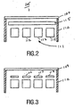
- An exemplary optical subsystem consists of two concentric rings of six (inner) and 12 (outer) LED assemblies around a central (optical) axis, each assembly having a collimator lens of 15 mm diameter, and a simple light sensor assembly consisting of a hexagonal diffuser plate, a white paper tube forming a simple integrator structure, both also of 15 mm diameter; and four photodiode packages arranged inside the integrator chamber.
- the light sensor assembly was centered on the optical axis and extended vertically from the tops of the collimators down to the level of the LED chips.
- a planar mirror with an antireflection coating positioned between the main condenser lens and the target light guide was used as a partial reflector. This arrangement gave satisfactory light uniformity across the photodiode array. Better integration, leading to higher uniformity, is possible using a more carefully and accurately assembled design, at the expense of less total light collection.
- each LED package in the LED array may have an individual photodiode associated with it. Two different embodiments of such an association are shown for individual LED packages in Figs. 4 and 5.
- Fig. 4 shows a sealed LED package 119, including an LED chip 121 mounted on a substrate 123. Also mounted on the substrate 123 next to the LED chip 121 is a photodiode chip 122, positioned to measure light output from the LED. Covering LED chip 121 and photodiode chip 122 is lens 126, for directing light from the LED in a forward direction.
- Fig. 5 shows a similar arrangement to that of Fig. 4, except that instead of having the photodiode chip mounted inside the sealed LED assembly 126, a separate photodiode package 152 is positioned to measure light output from the LED package 150.
- LED package 150 includes LED chip 151 mounted on substrate 153 and covered by lens 156.
- Fig. 6 shows another arrangement in which an array of three LED packages 161, 162 and 163 are associated with a single photodiode 164.
- the controller 30 translates the feedback from the photodiode 24 into color point measurements, which are compared with desired settings provided via user inputs 40. Based on the comparison, the controller 30 decides whether the desired color balance is present, and accordingly signals the current regulators 11, 13,15 for the respective diodes 10,12, 14. A power input from the AC converter 50 is thus translated into current outputs, which control the light intensity for the respective colors red, green, and blue to obtain the desired color balance.
- the diodes fore each color of the array are kept at common potential by wiring on the substrate 16.
- User controls for the desired settings include inputs 41, 42, 43 for the respective colors, and a dimmer 44 which controls overall intensity of the resulting white light.
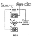
- Fig. 8 depicts the control logic for the luminaire of Fig. 7.
- the lamp is turned on (31)
- power is provided to the LEDs and a measuring sequence is initiated (32).
- Color point measurements are compared (33) with desired settings, which are stored (34) pursuant to user adjustment (35). Based on this comparison, it is determined (36) whether color adjustments are necessary, and if so, adjustments are made (37) and the measuring sequence is repeated (32). If it is determined that color adjustments are not necessary (36), the controller will wait for a predetermined measuring interval (38) before repeating the measuring sequence (32).
Abstract
Description
- This invention relates to a white light emitting luminaire having an array of red, green and blue light emitting diodes (LEDs) and a control system for adjusting the light output of the individual components to maintain a desired color balance (chromaticity), and more particularly relates to such a luminaire having specific light sensor configurstions for optical feedback.
- White light emitting luminaries having arrays of red, green and blue LEDs (also known as RGB LED luminaries) are of interest for several reasons, including efficiency and low cost, and the ability to adjust the chromaticity of the light output.
- One of the central problems to be addressed is the variation in light output of the LEDs from chip to chip, as well as over the life of each chip. Light output of the LEDs also varies inversely with temperature, but not uniformly for each color. In addition, light output will vary with the failure of individual chips within an LED array.
- United States Patent 6,127,783, discloses a white light emitting luminaire with electronically adjusted color balance. The luminaire includes a plurality of LEDs in each of the colors red, green and blue with a separate power supply for each color and a photodiode arranged to measure the light output of all the LEDs. The light output of each color is measured by an electronic control circuit which turns off the LEDs for the colors not being measured in a sequence of time pulses. The measured light output for each color is compared to a desired output, which may be determined by user inputs, and corrections to the current for each color are made accordingly.
- In order to accurately control the output of such a luminaire, the total delivered light must be monitored accurately. This requires placing the photodiodes in such a manner that an equal fraction of light is sampled from each LED while allowing sufficient stray light from the LEDs to fall on the photodiode(s) to insure satisfactory operation of the feedback loop.
- The invention provides several optical configurations for positioning one or more photodiodes, optionally with various color filters, in and around the lightpath of a RGB LED luminaire to achieve an equal fraction of light sampled from each LED in order that the total light output can be monitored accurately. Only minor modifications to a standard RGB LED luminaire's optical system are needed, and efficiency and other performance specifications are substantially unaffected. With the photodiodes so positioned, feedback signals are available to the control electronics to regulate both total light output and color balance.
- In a first embodiment of the invention, a partially reflecting element (typically about 1% reflection is sufficient) is positioned within the lightpath, after the main condenser lens, the partially reflecting element positioned and shaped to reflect a small portion of the output beam back through the condenser lens to focus at or slightly above the intersection of the optic axis with the plane of the LED array. At this focus is placed a light sensor assembly, including one or more photodiode(s), a white integrating chamber surrounding the photodiodes and a diffuser such as a planar diffusing screen between the chamber and the condensing lens. The light sensor assembly is arranged such that over a significant area (several times the size of one photodiode package) the flux from each LED is nearly constant While this embodiment is the most elaborate, it offers the best performance, economy, and versatility.
- In each of the embodiments, color filters may be associated with the photodiodes to render them selective to a particular spectral region of the RGB output, thus avoiding the need to pulse the LEDs and photodiodes as described in USP 6,127,783.
- Fig. 1 shows a cross section of one embodiment of a LED luminaire of the invention, including a light sensor assembly positioned in the center of an array of red, green and blue emitting LEDs, and a partially reflecting element placed in the path of the combined light output of the array;
- Fig. 2 shows details of the light sensor assembly of Fig. 1, including a photodiode array, a diffuser, an integrator and an optional variable color filter,
- Fig. 3 shows an alternate embodiment of the light sensor assembly of Fig. 2, including individual color filters associated with each photodiode;
- Fig. 4 shows in cross section a sealed package containing individual LED of the LED array, the sealed package including an associated photodiode;
- Fig. 5 shows in cross section a sealed LED package with an associated photodiode;
- Fig. 6 shows an array of three LED packages with an associated photodiode;
- Fig. 7 is a schematic diagram of the optical and electrical systems of one embodiment of the RGB LED luminaire of the invention including optical feedback and control; and
- Fig. 8 is a diagram of the logic sequence for the optical feedback and control portion of the luminaire of Fig. 7.
- Referring to the drawings. Fig. 1 is a schematic cross-section of one embodiment of the optical components of an RGB LED luminaire of the invention, an LED array 101 comprises individual LED assemblies (102,103,104) arranged in two concentric rings of individual LED assemblies around a central axis A. Bach LED assembly includes a sealed
LED package 126 and acollimator lens 120. Located on the central axis A is alight sensor assembly 105, including adiffuser 109, anintegrator 110, and an array of photodiodes 112,113,114 (Figs. 2 and 3). - A
main condenser lens 106 directs the light output from the LED array 101 toward atarget light guide 108. Apartial reflector 107 of appropriate shape is placed in the region between themain condenser lens 106 and thetarget light guide 108. Thepartial reflector 107 should have a total reflectivity of about 1 percent, which is less than that of most optical elements. This low reflectivity may be obtained by coating the optical element with a conventional anti-reflecting coating. The best results were obtained with a slightly aspheric concave shape, as illustrated in Fig. 1, but reasonably good results have also been obtained with a plane mirror configuration. Uncoated glass or plastic will work as well, but will needlessly reduce the overall system efficiency. - The
light sensor assembly 105 is illustrated schematically in Fig. 1 as the single cylindrical object on axis near the center of the LED array. Many different configurations are possible, including single or multiple photodiodes and simpler or more elaborate integrator structures. Two representative embodiments are shown in Figs. 2 and 3, in which the light sensor assembly includes adiffuser 109, anintegrator 110 and aphotodiode array 111. - The
light sensor assembly 105 may be read synchronously with the pulsing of the different color LEDs in the LED array in the manner described in U.S. patent 6,127,783, in order to provide the information needed to adjust the color balance of the LED luminaire. Alternatively, pulsing of the LEDs may be avoided by the use of color filters to isolate the light output of the different color LEDs for measurement by the photodiodes. In one possible embodiment, a single variable color filter 115, shown in Fig. 2, may be periodically tuned to different color wavelength bands during light sensing. In another possible embodiment, different fixed color filters 116,117,118, may be associated withindividual photodiodes 112, 113, 114, as shown in Fig. 3. - An exemplary optical subsystem consists of two concentric rings of six (inner) and 12 (outer) LED assemblies around a central (optical) axis, each assembly having a collimator lens of 15 mm diameter, and a simple light sensor assembly consisting of a hexagonal diffuser plate, a white paper tube forming a simple integrator structure, both also of 15 mm diameter; and four photodiode packages arranged inside the integrator chamber. The light sensor assembly was centered on the optical axis and extended vertically from the tops of the collimators down to the level of the LED chips. A planar mirror with an antireflection coating positioned between the main condenser lens and the target light guide was used as a partial reflector. This arrangement gave satisfactory light uniformity across the photodiode array. Better integration, leading to higher uniformity, is possible using a more carefully and accurately assembled design, at the expense of less total light collection.
- Alternatives to the centrally located
light sensor 105 are of course possible. For example, each LED package in the LED array may have an individual photodiode associated with it. Two different embodiments of such an association are shown for individual LED packages in Figs. 4 and 5. - Fig. 4 shows a sealed
LED package 119, including anLED chip 121 mounted on asubstrate 123. Also mounted on thesubstrate 123 next to theLED chip 121 is aphotodiode chip 122, positioned to measure light output from the LED. CoveringLED chip 121 andphotodiode chip 122 islens 126, for directing light from the LED in a forward direction. - Fig. 5 shows a similar arrangement to that of Fig. 4, except that instead of having the photodiode chip mounted inside the sealed
LED assembly 126, aseparate photodiode package 152 is positioned to measure light output from theLED package 150.LED package 150 includesLED chip 151 mounted onsubstrate 153 and covered bylens 156. - Fig. 6 shows another arrangement in which an array of three
LED packages single photodiode 164. - Referring to Fig. 7, a schematic diagram of the optical and electrical components of one embodiment of a luminaire of the invention, the
controller 30 translates the feedback from thephotodiode 24 into color point measurements, which are compared with desired settings provided viauser inputs 40. Based on the comparison, thecontroller 30 decides whether the desired color balance is present, and accordingly signals thecurrent regulators respective diodes AC converter 50 is thus translated into current outputs, which control the light intensity for the respective colors red, green, and blue to obtain the desired color balance. The diodes fore each color of the array are kept at common potential by wiring on the substrate 16. User controls for the desired settings include inputs 41, 42, 43 for the respective colors, and a dimmer 44 which controls overall intensity of the resulting white light. - Fig. 8 depicts the control logic for the luminaire of Fig. 7. When the lamp is turned on (31), power is provided to the LEDs and a measuring sequence is initiated (32). Color point measurements are compared (33) with desired settings, which are stored (34) pursuant to user adjustment (35). Based on this comparison, it is determined (36) whether color adjustments are necessary, and if so, adjustments are made (37) and the measuring sequence is repeated (32). If it is determined that color adjustments are not necessary (36), the controller will wait for a predetermined measuring interval (38) before repeating the measuring sequence (32).
Claims (7)
- An LED luminaire (100) comprising an array of LEDs (101) comprising at least one LED (102, 103, 104) in each of a plurality of colors, a sensor arranged to measure the light output from all the LEDs, and a condenser lens (106) positioned to direct the combined light output of the array of LEDs to a target light guide (108), characterized by
a partially reflecting element (107) positioned to reflect a portion of the light output from the condenser lens back toward the LED array,
wherein said light sensor (105) is positioned to intercept and measure at least a portion of the reflected light. - The LED luminaire of claim 1 further comprising;
means (50) for supplying electrical current to said LED array (101), whereby said LEDs (102,103,104) in each said color have a light output, and the LED array has a combined light output, means (32, 115) for providing the reflected light output of each color separately to the light sensor (105),
means (33) for comparing the measured light output for each color to a respective desired light output for each color, and
means (37) for adjusting the electrical current to the LEDs in each color based on said comparison, whereby a desired combined light output may be achieved. - The LED luminaire of claim 2 in which the means (32, 115) for providing the reflected light output of each color separately to the light sensor (105) comprises means for selectively turning off the LEDs so that the light sensor measures the light output for each color separately in a series of time pulses.
- The LED huninaire of claim 2 in which the means (32, 115) for providing the reflected light output of each color separately to the light sensor (105) comprises color filter means (115) for selectively filtering out the light output of each separate LED color.
- The LED luminaire of claim 4 in which the light sensor comprises an array (111) of photodiodes (112, 113, 114).
- The LED luminaire of claim 5 in which color filter means (115) comprises separate color filters (116, 117, 118) associated with the individual photodiodes (112, 113, 114).
- The LED luminaire of claim 5 in which the light sensor additionally comprises a light diffuser (109) and a light integrator (110).
Applications Claiming Priority (3)
| Application Number | Priority Date | Filing Date | Title |
|---|---|---|---|
| US876661 | 2001-06-07 | ||
| US09/876,661 US6741351B2 (en) | 2001-06-07 | 2001-06-07 | LED luminaire with light sensor configurations for optical feedback |
| PCT/IB2002/002127 WO2002099333A1 (en) | 2001-06-07 | 2002-06-07 | Led luminaire with light sensor configurations for optical feedback |
Publications (2)
| Publication Number | Publication Date |
|---|---|
| EP1399694A1 EP1399694A1 (en) | 2004-03-24 |
| EP1399694B1 true EP1399694B1 (en) | 2006-08-09 |
Family
ID=25368301
Family Applications (1)
| Application Number | Title | Priority Date | Filing Date |
|---|---|---|---|
| EP02735758A Expired - Lifetime EP1399694B1 (en) | 2001-06-07 | 2002-06-07 | Led luminaire with light sensor configurations for optical feedback |
Country Status (9)
| Country | Link |
|---|---|
| US (1) | US6741351B2 (en) |
| EP (1) | EP1399694B1 (en) |
| JP (1) | JP2004533097A (en) |
| KR (1) | KR100832161B1 (en) |
| CN (1) | CN1240960C (en) |
| AT (1) | ATE335963T1 (en) |
| DE (1) | DE60213804T2 (en) |
| TW (1) | TW557587B (en) |
| WO (1) | WO2002099333A1 (en) |
Cited By (35)
| Publication number | Priority date | Publication date | Assignee | Title |
|---|---|---|---|---|
| US7926975B2 (en) | 2007-12-21 | 2011-04-19 | Altair Engineering, Inc. | Light distribution using a light emitting diode assembly |
| US7938562B2 (en) | 2008-10-24 | 2011-05-10 | Altair Engineering, Inc. | Lighting including integral communication apparatus |
| US7946729B2 (en) | 2008-07-31 | 2011-05-24 | Altair Engineering, Inc. | Fluorescent tube replacement having longitudinally oriented LEDs |
| US7976196B2 (en) | 2008-07-09 | 2011-07-12 | Altair Engineering, Inc. | Method of forming LED-based light and resulting LED-based light |
| US8118447B2 (en) | 2007-12-20 | 2012-02-21 | Altair Engineering, Inc. | LED lighting apparatus with swivel connection |
| US8214084B2 (en) | 2008-10-24 | 2012-07-03 | Ilumisys, Inc. | Integration of LED lighting with building controls |
| US8256924B2 (en) | 2008-09-15 | 2012-09-04 | Ilumisys, Inc. | LED-based light having rapidly oscillating LEDs |
| US8299695B2 (en) | 2009-06-02 | 2012-10-30 | Ilumisys, Inc. | Screw-in LED bulb comprising a base having outwardly projecting nodes |
| US8324817B2 (en) | 2008-10-24 | 2012-12-04 | Ilumisys, Inc. | Light and light sensor |
| US8330381B2 (en) | 2009-05-14 | 2012-12-11 | Ilumisys, Inc. | Electronic circuit for DC conversion of fluorescent lighting ballast |
| US8360599B2 (en) | 2008-05-23 | 2013-01-29 | Ilumisys, Inc. | Electric shock resistant L.E.D. based light |
| US8362710B2 (en) | 2009-01-21 | 2013-01-29 | Ilumisys, Inc. | Direct AC-to-DC converter for passive component minimization and universal operation of LED arrays |
| US8421366B2 (en) | 2009-06-23 | 2013-04-16 | Ilumisys, Inc. | Illumination device including LEDs and a switching power control system |
| US8444292B2 (en) | 2008-10-24 | 2013-05-21 | Ilumisys, Inc. | End cap substitute for LED-based tube replacement light |
| US8454193B2 (en) | 2010-07-08 | 2013-06-04 | Ilumisys, Inc. | Independent modules for LED fluorescent light tube replacement |
| US8523394B2 (en) | 2010-10-29 | 2013-09-03 | Ilumisys, Inc. | Mechanisms for reducing risk of shock during installation of light tube |
| US8541958B2 (en) | 2010-03-26 | 2013-09-24 | Ilumisys, Inc. | LED light with thermoelectric generator |
| US8540401B2 (en) | 2010-03-26 | 2013-09-24 | Ilumisys, Inc. | LED bulb with internal heat dissipating structures |
| US8556452B2 (en) | 2009-01-15 | 2013-10-15 | Ilumisys, Inc. | LED lens |
| US8596813B2 (en) | 2010-07-12 | 2013-12-03 | Ilumisys, Inc. | Circuit board mount for LED light tube |
| US8653984B2 (en) | 2008-10-24 | 2014-02-18 | Ilumisys, Inc. | Integration of LED lighting control with emergency notification systems |
| US8664880B2 (en) | 2009-01-21 | 2014-03-04 | Ilumisys, Inc. | Ballast/line detection circuit for fluorescent replacement lamps |
| US8674626B2 (en) | 2008-09-02 | 2014-03-18 | Ilumisys, Inc. | LED lamp failure alerting system |
| US8870415B2 (en) | 2010-12-09 | 2014-10-28 | Ilumisys, Inc. | LED fluorescent tube replacement light with reduced shock hazard |
| US8901823B2 (en) | 2008-10-24 | 2014-12-02 | Ilumisys, Inc. | Light and light sensor |
| US9057493B2 (en) | 2010-03-26 | 2015-06-16 | Ilumisys, Inc. | LED light tube with dual sided light distribution |
| US9072171B2 (en) | 2011-08-24 | 2015-06-30 | Ilumisys, Inc. | Circuit board mount for LED light |
| US9163794B2 (en) | 2012-07-06 | 2015-10-20 | Ilumisys, Inc. | Power supply assembly for LED-based light tube |
| US9184518B2 (en) | 2012-03-02 | 2015-11-10 | Ilumisys, Inc. | Electrical connector header for an LED-based light |
| US9271367B2 (en) | 2012-07-09 | 2016-02-23 | Ilumisys, Inc. | System and method for controlling operation of an LED-based light |
| US9267650B2 (en) | 2013-10-09 | 2016-02-23 | Ilumisys, Inc. | Lens for an LED-based light |
| US9285084B2 (en) | 2013-03-14 | 2016-03-15 | Ilumisys, Inc. | Diffusers for LED-based lights |
| US9510400B2 (en) | 2014-05-13 | 2016-11-29 | Ilumisys, Inc. | User input systems for an LED-based light |
| US9574717B2 (en) | 2014-01-22 | 2017-02-21 | Ilumisys, Inc. | LED-based light with addressed LEDs |
| US10161568B2 (en) | 2015-06-01 | 2018-12-25 | Ilumisys, Inc. | LED-based light with canted outer walls |
Families Citing this family (179)
| Publication number | Priority date | Publication date | Assignee | Title |
|---|---|---|---|---|
| US7014336B1 (en) * | 1999-11-18 | 2006-03-21 | Color Kinetics Incorporated | Systems and methods for generating and modulating illumination conditions |
| JP2003510856A (en) * | 1999-09-29 | 2003-03-18 | カラー・キネティックス・インコーポレーテッド | Combined illumination and calibration apparatus and calibration method for multiple LEDs |
| US20050195598A1 (en) * | 2003-02-07 | 2005-09-08 | Dancs Imre J. | Projecting light and images from a device |
| KR100450815B1 (en) * | 2002-02-01 | 2004-10-01 | 삼성전자주식회사 | Illumination system and projection display device employing it |
| MXPA04011283A (en) | 2002-05-13 | 2005-02-17 | Johnson & Son Inc S C | Coordinated emission of fragrance, light, and sound. |
| JP4048164B2 (en) * | 2003-01-10 | 2008-02-13 | シャープ株式会社 | Light emitting device |
| US6967447B2 (en) * | 2003-12-18 | 2005-11-22 | Agilent Technologies, Inc. | Pre-configured light modules |
| US7294816B2 (en) * | 2003-12-19 | 2007-11-13 | Avago Technologies Ecbu Ip (Singapore) Pte. Ltd. | LED illumination system having an intensity monitoring system |
| US7473879B2 (en) * | 2003-12-19 | 2009-01-06 | Avago Technologies Ecbu Ip (Singapore) Pte. Ltd. | LED illumination system having an intensity monitoring system |
| WO2005085704A1 (en) * | 2004-03-10 | 2005-09-15 | Aleksander Leonidovich Noginov | Decorative multicolour lighting set (variants) |
| US7354172B2 (en) * | 2004-03-15 | 2008-04-08 | Philips Solid-State Lighting Solutions, Inc. | Methods and apparatus for controlled lighting based on a reference gamut |
| US7633463B2 (en) * | 2004-04-30 | 2009-12-15 | Analog Devices, Inc. | Method and IC driver for series connected R, G, B LEDs |
| US20050259424A1 (en) | 2004-05-18 | 2005-11-24 | Zampini Thomas L Ii | Collimating and controlling light produced by light emitting diodes |
| US20060000963A1 (en) * | 2004-06-30 | 2006-01-05 | Ng Kee Y | Light source calibration |
| US7333011B2 (en) * | 2004-07-06 | 2008-02-19 | Honeywell International Inc. | LED-based luminaire utilizing optical feedback color and intensity control scheme |
| US7267546B2 (en) * | 2004-08-09 | 2007-09-11 | Ultradent Products, Inc. | Light meter for detecting and measuring intensity of two or more wavelengths of light |
| US20060052676A1 (en) * | 2004-09-07 | 2006-03-09 | Yulun Wang | Tele-presence system that allows for remote monitoring/observation and review of a patient and their medical records |
| US7351245B2 (en) * | 2004-09-21 | 2008-04-01 | Bernice Joy Rozinsky | Apparatus and method for dislodging object from throat |
| DK1794811T3 (en) | 2004-09-24 | 2011-09-26 | Koninkl Philips Electronics Nv | Lighting System |
| US20060087841A1 (en) * | 2004-10-27 | 2006-04-27 | United Epitaxy Company, Ltd. | LED luminaire with feedback control |
| GB2419750B (en) * | 2004-10-28 | 2007-03-21 | Premier Image Technology Corp | LED controller and control method thereof |
| KR20070086371A (en) | 2004-11-19 | 2007-08-27 | 코닌클리즈케 필립스 일렉트로닉스 엔.브이. | A feedback control system for controlling the light output of a led unit |
| JP4988586B2 (en) * | 2004-11-19 | 2012-08-01 | コーニンクレッカ フィリップス エレクトロニクス エヌ ヴィ | LED lighting device with optical feedback by image mapping on segmented photosensor |
| US20070273290A1 (en) * | 2004-11-29 | 2007-11-29 | Ian Ashdown | Integrated Modular Light Unit |
| EP1839463A4 (en) * | 2004-11-29 | 2009-03-04 | Tir Technology Lp | Integrated modular lighting unit |
| US20100096993A1 (en) * | 2004-11-29 | 2010-04-22 | Ian Ashdown | Integrated Modular Lighting Unit |
| CN101080659A (en) * | 2004-12-16 | 2007-11-28 | 皇家飞利浦电子股份有限公司 | A feedback controlled illumination system having an array of leds, and a detector among the leds |
| US7856152B2 (en) | 2005-03-23 | 2010-12-21 | Koninklijke Philips Electronics N.V. | Light condition recorder system and method |
| US20060226336A1 (en) * | 2005-03-23 | 2006-10-12 | Tir Systems Ltd. | Apparatus and method for collecting and detecting light emitted by a lighting apparatus |
| EP1861683A1 (en) * | 2005-03-23 | 2007-12-05 | Tir Systems Ltd. | Apparatus and method for collecting and detecting light emitted by a lighting apparatus |
| US20080296589A1 (en) * | 2005-03-24 | 2008-12-04 | Ingo Speier | Solid-State Lighting Device Package |
| EP1872401B1 (en) * | 2005-04-05 | 2018-09-19 | Philips Lighting Holding B.V. | Electronic device package with an integrated evaporator |
| ATE532384T1 (en) * | 2005-04-28 | 2011-11-15 | Koninkl Philips Electronics Nv | IMPROVED LIGHTING SYSTEM |
| US8016470B2 (en) * | 2007-10-05 | 2011-09-13 | Dental Equipment, Llc | LED-based dental exam lamp with variable chromaticity |
| RU2434368C2 (en) | 2005-06-03 | 2011-11-20 | Конинклейке Филипс Электроникс Н.В. | System and method of controlling led lamp |
| WO2007000699A1 (en) * | 2005-06-29 | 2007-01-04 | Koninklijke Philips Electronics N.V. | Control system for controlling the light output of a led luminaire |
| US7312430B2 (en) * | 2005-07-01 | 2007-12-25 | Avago Technologies Ecbuip Pte Ltd | System, display apparatus and method for providing controlled illumination using internal reflection |
| US7732753B2 (en) * | 2005-08-02 | 2010-06-08 | Koninklijke Philips Electronics N.V. | Illumination system having a light-transmissive plate with surface-modification structures |
| EP1935073A4 (en) * | 2005-09-20 | 2009-05-20 | Analog Devices Inc | Driving parallel strings of series connected leds |
| TWI263754B (en) * | 2005-10-05 | 2006-10-11 | Coretronic Corp | A LED (light-emitting diode) backlight module |
| US7765792B2 (en) | 2005-10-21 | 2010-08-03 | Honeywell International Inc. | System for particulate matter sensor signal processing |
| US7804260B2 (en) * | 2005-10-26 | 2010-09-28 | Koninklijke Philips Electronics N.V. | LED luminary system |
| US7926300B2 (en) | 2005-11-18 | 2011-04-19 | Cree, Inc. | Adaptive adjustment of light output of solid state lighting panels |
| US8278846B2 (en) * | 2005-11-18 | 2012-10-02 | Cree, Inc. | Systems and methods for calibrating solid state lighting panels |
| US8514210B2 (en) | 2005-11-18 | 2013-08-20 | Cree, Inc. | Systems and methods for calibrating solid state lighting panels using combined light output measurements |
| JP5166278B2 (en) | 2005-11-18 | 2013-03-21 | クリー インコーポレイテッド | Solid-state lighting tile |
| CN101313174A (en) * | 2005-11-21 | 2008-11-26 | 皇家飞利浦电子股份有限公司 | Lighting device |
| JP2009516894A (en) * | 2005-11-22 | 2009-04-23 | コーニンクレッカ フィリップス エレクトロニクス エヌ ヴィ | LED lighting system and control method |
| GB0524909D0 (en) * | 2005-12-06 | 2006-01-11 | Enfis Ltd | Improved LED array |
| WO2007069149A1 (en) * | 2005-12-16 | 2007-06-21 | Koninklijke Philips Electronics N.V. | Illumination device and method for controlling an illumination device |
| DE102005061204A1 (en) * | 2005-12-21 | 2007-07-05 | Perkinelmer Elcos Gmbh | Lighting device, lighting control device and lighting system |
| FR2896944B1 (en) * | 2006-01-31 | 2008-05-02 | Commissariat Energie Atomique | LIGHT EMITTING DEVICE WITH CHROMATIC CONTROL |
| US7734092B2 (en) * | 2006-03-07 | 2010-06-08 | Ancestry.Com Operations Inc. | Multiple image input for optical character recognition processing systems and methods |
| CA2648723A1 (en) * | 2006-04-21 | 2007-11-01 | Tir Technology Lp | Method and apparatus for light intensity control |
| US7766511B2 (en) | 2006-04-24 | 2010-08-03 | Integrated Illumination Systems | LED light fixture |
| JP2009538536A (en) | 2006-05-26 | 2009-11-05 | クリー エル イー ディー ライティング ソリューションズ インコーポレイテッド | Solid state light emitting device and method of manufacturing the same |
| CN101454613A (en) * | 2006-05-31 | 2009-06-10 | 科锐Led照明科技公司 | Lighting device with color control, and method of lighting |
| WO2007144837A1 (en) | 2006-06-15 | 2007-12-21 | Koninklijke Philips Electronics N.V. | Angle selective photo sensor structures for accurate color control, out coupling and background rejection, in led luminaries |
| US7906794B2 (en) | 2006-07-05 | 2011-03-15 | Koninklijke Philips Electronics N.V. | Light emitting device package with frame and optically transmissive element |
| WO2008023306A1 (en) * | 2006-08-25 | 2008-02-28 | Philips Intellectual Property & Standards Gmbh | Optical lighting device |
| CN101536179B (en) * | 2006-10-31 | 2011-05-25 | 皇家飞利浦电子股份有限公司 | Lighting device package |
| US7729941B2 (en) | 2006-11-17 | 2010-06-01 | Integrated Illumination Systems, Inc. | Apparatus and method of using lighting systems to enhance brand recognition |
| RU2470496C2 (en) * | 2006-12-11 | 2012-12-20 | Конинклейке Филипс Электроникс Н.В. | System and method of control over illuminators |
| EP2092797B1 (en) * | 2006-12-11 | 2012-11-21 | Koninklijke Philips Electronics N.V. | Method and apparatus for digital control of a lighting device |
| US8013538B2 (en) | 2007-01-26 | 2011-09-06 | Integrated Illumination Systems, Inc. | TRI-light |
| US8456388B2 (en) * | 2007-02-14 | 2013-06-04 | Cree, Inc. | Systems and methods for split processor control in a solid state lighting panel |
| IL189491A (en) * | 2007-02-20 | 2016-09-29 | Camtek Ltd | Led illumination for line scan camera |
| US8330393B2 (en) * | 2007-04-20 | 2012-12-11 | Analog Devices, Inc. | System for time-sequential LED-string excitation |
| EP2165113B1 (en) * | 2007-05-08 | 2016-06-22 | Cree, Inc. | Lighting devices and methods for lighting |
| US7712917B2 (en) * | 2007-05-21 | 2010-05-11 | Cree, Inc. | Solid state lighting panels with limited color gamut and methods of limiting color gamut in solid state lighting panels |
| US20090008662A1 (en) * | 2007-07-05 | 2009-01-08 | Ian Ashdown | Lighting device package |
| TWI455644B (en) * | 2007-07-31 | 2014-10-01 | Pixart Imaging Inc | Semiconductor device and method for calibrating the same |
| US20090033612A1 (en) * | 2007-07-31 | 2009-02-05 | Roberts John K | Correction of temperature induced color drift in solid state lighting displays |
| DE102007036978A1 (en) * | 2007-08-06 | 2009-02-12 | Tridonicatco Gmbh & Co. Kg | Device and method for controlling the light output |
| US8829820B2 (en) * | 2007-08-10 | 2014-09-09 | Cree, Inc. | Systems and methods for protecting display components from adverse operating conditions |
| CN101784872B (en) * | 2007-08-13 | 2012-12-05 | 皇家飞利浦电子股份有限公司 | Lighting device with adaptable color |
| US8742686B2 (en) | 2007-09-24 | 2014-06-03 | Integrated Illumination Systems, Inc. | Systems and methods for providing an OEM level networked lighting system |
| WO2009047693A2 (en) | 2007-10-12 | 2009-04-16 | Koninklijke Philips Electronics N.V. | Sensing coded light using retro reflectors |
| US8866410B2 (en) | 2007-11-28 | 2014-10-21 | Cree, Inc. | Solid state lighting devices and methods of manufacturing the same |
| US8823630B2 (en) * | 2007-12-18 | 2014-09-02 | Cree, Inc. | Systems and methods for providing color management control in a lighting panel |
| JP5108490B2 (en) * | 2007-12-19 | 2012-12-26 | オリンパス株式会社 | Lighting device for cell analyzer |
| US20110018465A1 (en) * | 2008-01-17 | 2011-01-27 | Koninklijke Philips Electronics N.V. | Method and apparatus for light intensity control |
| RU2526043C2 (en) | 2008-01-30 | 2014-08-20 | Конинклейке Филипс Электроникс Н.В. | Universal semiconductor device, module and method of operation |
| EP2269121A4 (en) * | 2008-03-20 | 2016-09-21 | Cooper Technologies Co | Managing ssl fixtures over plc networks |
| US8915609B1 (en) | 2008-03-20 | 2014-12-23 | Cooper Technologies Company | Systems, methods, and devices for providing a track light and portable light |
| US8452402B2 (en) * | 2008-04-23 | 2013-05-28 | Medtronic, Inc. | Optical sensing device for use in a medical device |
| US8255487B2 (en) | 2008-05-16 | 2012-08-28 | Integrated Illumination Systems, Inc. | Systems and methods for communicating in a lighting network |
| WO2009144644A1 (en) * | 2008-05-27 | 2009-12-03 | Nxp B.V. | Light sensor arrangement |
| US9276766B2 (en) | 2008-09-05 | 2016-03-01 | Ketra, Inc. | Display calibration systems and related methods |
| US10210750B2 (en) | 2011-09-13 | 2019-02-19 | Lutron Electronics Co., Inc. | System and method of extending the communication range in a visible light communication system |
| US9509525B2 (en) | 2008-09-05 | 2016-11-29 | Ketra, Inc. | Intelligent illumination device |
| US8773336B2 (en) * | 2008-09-05 | 2014-07-08 | Ketra, Inc. | Illumination devices and related systems and methods |
| US20100118543A1 (en) * | 2008-11-07 | 2010-05-13 | Itramas International, Inc. | Methodology of optical feedback for led lighting |
| US8632208B2 (en) * | 2008-11-07 | 2014-01-21 | Itramas International, Inc. | Methodology of providing white lighting with colour combination |
| US8550657B2 (en) * | 2008-11-07 | 2013-10-08 | Itramas International, Inc. | Methodology of maintaining CCT for white light using LED |
| US8215814B2 (en) * | 2008-11-21 | 2012-07-10 | Dbm Reflex Enterprises Inc. | Solid state optical illumination apparatus |
| DE102008064397A1 (en) | 2008-12-22 | 2010-06-24 | Tridonicatco Schweiz Ag | LED arrangement with light sensor |
| US8576406B1 (en) | 2009-02-25 | 2013-11-05 | Physical Optics Corporation | Luminaire illumination system and method |
| US8585245B2 (en) | 2009-04-23 | 2013-11-19 | Integrated Illumination Systems, Inc. | Systems and methods for sealing a lighting fixture |
| EP2291057A3 (en) * | 2009-08-24 | 2016-11-16 | Siemens Schweiz AG | Method and device for monitoring and adapting to interference in the luminous flux of light sources in technical assemblies and in signals |
| JP4975797B2 (en) * | 2009-10-14 | 2012-07-11 | シャープ株式会社 | LIGHTING DEVICE, VEHICLE LIGHT, AND VEHICLE |
| IT1396088B1 (en) † | 2009-10-16 | 2012-11-09 | Solari Di Udine S P A | LUMINOUS LED SIGNALING DEVICE AND ITS CONTROL PROCEDURE |
| CA2780352A1 (en) * | 2009-12-22 | 2011-06-30 | Alcon Research, Ltd. | Light collector for a white light led illuminator |
| US10690540B2 (en) * | 2015-10-06 | 2020-06-23 | View, Inc. | Multi-sensor having a light diffusing element around a periphery of a ring of photosensors |
| CN102346231A (en) * | 2010-07-30 | 2012-02-08 | 致茂电子(苏州)有限公司 | Sunlight simulator provided with detection device and solar battery detection device |
| US8496353B2 (en) | 2010-09-14 | 2013-07-30 | Tsmc Solid State Lighting Ltd. | Light-emitting diode (LED) module with light sensor configurations for optical feedback |
| USRE49454E1 (en) | 2010-09-30 | 2023-03-07 | Lutron Technology Company Llc | Lighting control system |
| US9386668B2 (en) | 2010-09-30 | 2016-07-05 | Ketra, Inc. | Lighting control system |
| US20120099303A1 (en) * | 2010-10-26 | 2012-04-26 | Industrial Technology Research Institute | Cct modulating method, led light source module, and package structure thereof |
| DE102010043295B4 (en) * | 2010-11-03 | 2020-10-08 | Lisa Dräxlmaier GmbH | Light emitter module |
| DE102010043296B4 (en) * | 2010-11-03 | 2020-10-08 | Lisa Dräxlmaier GmbH | Light emitter module with deflecting optics |
| TWI438889B (en) * | 2010-12-01 | 2014-05-21 | Hon Hai Prec Ind Co Ltd | Package structure of light emitting diode |
| CN102563383A (en) * | 2010-12-15 | 2012-07-11 | 鸿富锦精密工业(深圳)有限公司 | Light-emitting diode light source module |
| JP5247892B2 (en) * | 2011-03-07 | 2013-07-24 | パイオニア株式会社 | Emission status measurement device |
| US9066381B2 (en) | 2011-03-16 | 2015-06-23 | Integrated Illumination Systems, Inc. | System and method for low level dimming |
| US9967940B2 (en) | 2011-05-05 | 2018-05-08 | Integrated Illumination Systems, Inc. | Systems and methods for active thermal management |
| DE102011102567B4 (en) | 2011-05-26 | 2023-05-25 | OSRAM Opto Semiconductors Gesellschaft mit beschränkter Haftung | lighting device |
| WO2012168877A1 (en) * | 2011-06-10 | 2012-12-13 | Koninklijke Philips Electronics N.V. | Arrangement for light balancing |
| US9609720B2 (en) | 2011-07-26 | 2017-03-28 | Hunter Industries, Inc. | Systems and methods for providing power and data to lighting devices |
| US10874003B2 (en) | 2011-07-26 | 2020-12-22 | Hunter Industries, Inc. | Systems and methods for providing power and data to devices |
| US11917740B2 (en) | 2011-07-26 | 2024-02-27 | Hunter Industries, Inc. | Systems and methods for providing power and data to devices |
| US8710770B2 (en) | 2011-07-26 | 2014-04-29 | Hunter Industries, Inc. | Systems and methods for providing power and data to lighting devices |
| US9521725B2 (en) | 2011-07-26 | 2016-12-13 | Hunter Industries, Inc. | Systems and methods for providing power and data to lighting devices |
| US20150237700A1 (en) | 2011-07-26 | 2015-08-20 | Hunter Industries, Inc. | Systems and methods to control color and brightness of lighting devices |
| US8749145B2 (en) | 2011-12-05 | 2014-06-10 | Mojo Labs, Inc. | Determination of lighting contributions for light fixtures using optical bursts |
| US8749146B2 (en) | 2011-12-05 | 2014-06-10 | Mojo Labs, Inc. | Auto commissioning of light fixture using optical bursts |
| US8842009B2 (en) | 2012-06-07 | 2014-09-23 | Mojo Labs, Inc. | Multiple light sensor multiple light fixture control |
| US8894437B2 (en) | 2012-07-19 | 2014-11-25 | Integrated Illumination Systems, Inc. | Systems and methods for connector enabling vertical removal |
| US8974077B2 (en) | 2012-07-30 | 2015-03-10 | Ultravision Technologies, Llc | Heat sink for LED light source |
| DE102012215702A1 (en) * | 2012-09-05 | 2014-03-06 | Osram Gmbh | lighting device |
| US9379578B2 (en) | 2012-11-19 | 2016-06-28 | Integrated Illumination Systems, Inc. | Systems and methods for multi-state power management |
| US9420665B2 (en) | 2012-12-28 | 2016-08-16 | Integration Illumination Systems, Inc. | Systems and methods for continuous adjustment of reference signal to control chip |
| US9485814B2 (en) | 2013-01-04 | 2016-11-01 | Integrated Illumination Systems, Inc. | Systems and methods for a hysteresis based driver using a LED as a voltage reference |
| US9804024B2 (en) | 2013-03-14 | 2017-10-31 | Mojo Labs, Inc. | Light measurement and/or control translation for daylighting |
| US10687697B2 (en) * | 2013-03-15 | 2020-06-23 | Stryker Corporation | Endoscopic light source and imaging system |
| KR101472833B1 (en) * | 2013-07-16 | 2014-12-24 | 에스엘 주식회사 | Current controlling apparatus for automotive lamp |
| US9247605B1 (en) | 2013-08-20 | 2016-01-26 | Ketra, Inc. | Interference-resistant compensation for illumination devices |
| US9345097B1 (en) | 2013-08-20 | 2016-05-17 | Ketra, Inc. | Interference-resistant compensation for illumination devices using multiple series of measurement intervals |
| US9332598B1 (en) | 2013-08-20 | 2016-05-03 | Ketra, Inc. | Interference-resistant compensation for illumination devices having multiple emitter modules |
| USRE48955E1 (en) | 2013-08-20 | 2022-03-01 | Lutron Technology Company Llc | Interference-resistant compensation for illumination devices having multiple emitter modules |
| US9769899B2 (en) | 2014-06-25 | 2017-09-19 | Ketra, Inc. | Illumination device and age compensation method |
| US9155155B1 (en) | 2013-08-20 | 2015-10-06 | Ketra, Inc. | Overlapping measurement sequences for interference-resistant compensation in light emitting diode devices |
| US9651632B1 (en) | 2013-08-20 | 2017-05-16 | Ketra, Inc. | Illumination device and temperature calibration method |
| USRE48956E1 (en) | 2013-08-20 | 2022-03-01 | Lutron Technology Company Llc | Interference-resistant compensation for illumination devices using multiple series of measurement intervals |
| US9237620B1 (en) | 2013-08-20 | 2016-01-12 | Ketra, Inc. | Illumination device and temperature compensation method |
| US9578724B1 (en) | 2013-08-20 | 2017-02-21 | Ketra, Inc. | Illumination device and method for avoiding flicker |
| US9360174B2 (en) | 2013-12-05 | 2016-06-07 | Ketra, Inc. | Linear LED illumination device with improved color mixing |
| US9736895B1 (en) | 2013-10-03 | 2017-08-15 | Ketra, Inc. | Color mixing optics for LED illumination device |
| EP2882261A1 (en) * | 2013-12-05 | 2015-06-10 | Helvar Oy Ab | Improving reliability of a lighting apparatus |
| US9146028B2 (en) | 2013-12-05 | 2015-09-29 | Ketra, Inc. | Linear LED illumination device with improved rotational hinge |
| EP2886941B1 (en) * | 2013-12-17 | 2019-03-13 | Goodrich Lighting Systems GmbH | Aircraft light unit and aircraft having such aircraft light unit |
| US9557214B2 (en) | 2014-06-25 | 2017-01-31 | Ketra, Inc. | Illumination device and method for calibrating an illumination device over changes in temperature, drive current, and time |
| US9392663B2 (en) | 2014-06-25 | 2016-07-12 | Ketra, Inc. | Illumination device and method for controlling an illumination device over changes in drive current and temperature |
| US9736903B2 (en) | 2014-06-25 | 2017-08-15 | Ketra, Inc. | Illumination device and method for calibrating and controlling an illumination device comprising a phosphor converted LED |
| US10161786B2 (en) | 2014-06-25 | 2018-12-25 | Lutron Ketra, Llc | Emitter module for an LED illumination device |
| US9510416B2 (en) | 2014-08-28 | 2016-11-29 | Ketra, Inc. | LED illumination device and method for accurately controlling the intensity and color point of the illumination device over time |
| US9392660B2 (en) | 2014-08-28 | 2016-07-12 | Ketra, Inc. | LED illumination device and calibration method for accurately characterizing the emission LEDs and photodetector(s) included within the LED illumination device |
| DE102014226661A1 (en) * | 2014-12-19 | 2016-06-23 | Osram Gmbh | lighting device |
| US9237612B1 (en) | 2015-01-26 | 2016-01-12 | Ketra, Inc. | Illumination device and method for determining a target lumens that can be safely produced by an illumination device at a present temperature |
| US9237623B1 (en) | 2015-01-26 | 2016-01-12 | Ketra, Inc. | Illumination device and method for determining a maximum lumens that can be safely produced by the illumination device to achieve a target chromaticity |
| US9485813B1 (en) | 2015-01-26 | 2016-11-01 | Ketra, Inc. | Illumination device and method for avoiding an over-power or over-current condition in a power converter |
| US10070496B2 (en) | 2015-03-30 | 2018-09-04 | Mojo Labs, Inc. | Task to wall color control |
| US10918030B2 (en) | 2015-05-26 | 2021-02-16 | Hunter Industries, Inc. | Decoder systems and methods for irrigation control |
| US10228711B2 (en) | 2015-05-26 | 2019-03-12 | Hunter Industries, Inc. | Decoder systems and methods for irrigation control |
| US10060599B2 (en) | 2015-05-29 | 2018-08-28 | Integrated Illumination Systems, Inc. | Systems, methods and apparatus for programmable light fixtures |
| US10030844B2 (en) | 2015-05-29 | 2018-07-24 | Integrated Illumination Systems, Inc. | Systems, methods and apparatus for illumination using asymmetrical optics |
| WO2016203423A1 (en) * | 2015-06-16 | 2016-12-22 | Sklaer Gmbh | Lighting device, in particular for lighting exhibition objects |
| FR3041152B1 (en) | 2015-09-10 | 2018-07-27 | Aledia | LIGHT EMITTING DEVICE WITH INTEGRATED LIGHT SENSOR |
| FR3046298B1 (en) * | 2015-12-23 | 2018-01-26 | Commissariat A L'energie Atomique Et Aux Energies Alternatives | OPTOELECTRONIC LIGHT EMISSION DEVICE |
| JPWO2017175391A1 (en) * | 2016-04-08 | 2019-03-28 | オリンパス株式会社 | Illuminating device and endoscope provided with the same |
| US10708991B2 (en) | 2017-01-25 | 2020-07-07 | Ledmotive Technologies, S.L. | Controlling lighting devices |
| DE102017108036A1 (en) * | 2017-04-13 | 2018-10-18 | Osram Gmbh | CONTROL OF LIGHTING DEVICE HAVING AT LEAST TWO ELECTRIC LIGHT SOURCES |
| FR3076171B1 (en) * | 2017-12-22 | 2021-10-29 | Valeo Vision | CALIBRATION OF A LIGHT MODULE WITH ELECTROLUMINESCENT ELEMENTS |
| US11272599B1 (en) | 2018-06-22 | 2022-03-08 | Lutron Technology Company Llc | Calibration procedure for a light-emitting diode light source |
| US10831032B2 (en) | 2019-02-28 | 2020-11-10 | Microsoft Technology Licensing, Llc | Photo-sensing reflectors for compact display module assembly |
| US11276986B2 (en) | 2019-02-28 | 2022-03-15 | Microsoft Technologly Licensing, LLC | Photo-sensing reflectors for compact display module assembly comprising a reflective coating on a light receiving surface of a reflective photodiode |
| JP7007595B2 (en) * | 2019-05-31 | 2022-01-24 | 日亜化学工業株式会社 | Manufacturing method of light emitting device |
| US10801714B1 (en) | 2019-10-03 | 2020-10-13 | CarJamz, Inc. | Lighting device |
| JP2022055932A (en) * | 2020-09-29 | 2022-04-08 | パナソニックIpマネジメント株式会社 | Light source device |
Family Cites Families (13)
| Publication number | Priority date | Publication date | Assignee | Title |
|---|---|---|---|---|
| US3760174A (en) * | 1972-05-31 | 1973-09-18 | Westinghouse Electric Corp | Programmable light source |
| US4810937A (en) * | 1986-04-28 | 1989-03-07 | Karel Havel | Multicolor optical device |
| US5471052A (en) * | 1993-10-25 | 1995-11-28 | Eaton Corporation | Color sensor system using a secondary light receiver |
| US5697584A (en) * | 1995-07-27 | 1997-12-16 | Union Switch & Signal Inc. | Railroad searchlight signal with solid state illuminant and aspect indication |
| US5838451A (en) * | 1995-12-22 | 1998-11-17 | Accuracy Microsensors, Inc. | Optoelectronic spectral analysis system |
| GB2309299B (en) * | 1996-01-16 | 2000-06-07 | Mars Inc | Sensing device |
| US5739915A (en) * | 1996-05-08 | 1998-04-14 | United Microelectronics Corp. | Electro-optical system for scanning color documents |
| US5923413A (en) * | 1996-11-15 | 1999-07-13 | Interbold | Universal bank note denominator and validator |
| GB9708861D0 (en) * | 1997-04-30 | 1997-06-25 | Signal House Limited | Traffic signals |
| US6525819B1 (en) * | 1998-09-02 | 2003-02-25 | Pocketspec Technologies Inc. | Colorimeter for dental applications |
| US6127783A (en) * | 1998-12-18 | 2000-10-03 | Philips Electronics North America Corp. | LED luminaire with electronically adjusted color balance |
| EP1208367A4 (en) * | 1999-08-06 | 2007-03-07 | Cambridge Res & Instrmnt Inc | Spectral imaging system |
| US6426704B1 (en) * | 2000-08-17 | 2002-07-30 | Power Signal Technologies, Inc. | Modular upgradable solid state light source for traffic control |
-
2001
- 2001-06-07 US US09/876,661 patent/US6741351B2/en not_active Expired - Lifetime
-
2002
- 2002-06-07 KR KR1020037001707A patent/KR100832161B1/en active IP Right Grant
- 2002-06-07 AT AT02735758T patent/ATE335963T1/en not_active IP Right Cessation
- 2002-06-07 EP EP02735758A patent/EP1399694B1/en not_active Expired - Lifetime
- 2002-06-07 CN CNB028114531A patent/CN1240960C/en not_active Expired - Lifetime
- 2002-06-07 JP JP2003502416A patent/JP2004533097A/en active Pending
- 2002-06-07 WO PCT/IB2002/002127 patent/WO2002099333A1/en active IP Right Grant
- 2002-06-07 DE DE60213804T patent/DE60213804T2/en not_active Expired - Lifetime
- 2002-06-18 TW TW091113240A patent/TW557587B/en not_active IP Right Cessation
Cited By (54)
| Publication number | Priority date | Publication date | Assignee | Title |
|---|---|---|---|---|
| US8118447B2 (en) | 2007-12-20 | 2012-02-21 | Altair Engineering, Inc. | LED lighting apparatus with swivel connection |
| US8928025B2 (en) | 2007-12-20 | 2015-01-06 | Ilumisys, Inc. | LED lighting apparatus with swivel connection |
| US7926975B2 (en) | 2007-12-21 | 2011-04-19 | Altair Engineering, Inc. | Light distribution using a light emitting diode assembly |
| US8360599B2 (en) | 2008-05-23 | 2013-01-29 | Ilumisys, Inc. | Electric shock resistant L.E.D. based light |
| US8807785B2 (en) | 2008-05-23 | 2014-08-19 | Ilumisys, Inc. | Electric shock resistant L.E.D. based light |
| US7976196B2 (en) | 2008-07-09 | 2011-07-12 | Altair Engineering, Inc. | Method of forming LED-based light and resulting LED-based light |
| US7946729B2 (en) | 2008-07-31 | 2011-05-24 | Altair Engineering, Inc. | Fluorescent tube replacement having longitudinally oriented LEDs |
| US8674626B2 (en) | 2008-09-02 | 2014-03-18 | Ilumisys, Inc. | LED lamp failure alerting system |
| US8256924B2 (en) | 2008-09-15 | 2012-09-04 | Ilumisys, Inc. | LED-based light having rapidly oscillating LEDs |
| US8444292B2 (en) | 2008-10-24 | 2013-05-21 | Ilumisys, Inc. | End cap substitute for LED-based tube replacement light |
| US9101026B2 (en) | 2008-10-24 | 2015-08-04 | Ilumisys, Inc. | Integration of LED lighting with building controls |
| US8324817B2 (en) | 2008-10-24 | 2012-12-04 | Ilumisys, Inc. | Light and light sensor |
| US8901823B2 (en) | 2008-10-24 | 2014-12-02 | Ilumisys, Inc. | Light and light sensor |
| US9585216B2 (en) | 2008-10-24 | 2017-02-28 | Ilumisys, Inc. | Integration of LED lighting with building controls |
| US9398661B2 (en) | 2008-10-24 | 2016-07-19 | Ilumisys, Inc. | Light and light sensor |
| US9635727B2 (en) | 2008-10-24 | 2017-04-25 | Ilumisys, Inc. | Light and light sensor |
| US10342086B2 (en) | 2008-10-24 | 2019-07-02 | Ilumisys, Inc. | Integration of LED lighting with building controls |
| US10036549B2 (en) | 2008-10-24 | 2018-07-31 | Ilumisys, Inc. | Lighting including integral communication apparatus |
| US9353939B2 (en) | 2008-10-24 | 2016-05-31 | iLumisys, Inc | Lighting including integral communication apparatus |
| US7938562B2 (en) | 2008-10-24 | 2011-05-10 | Altair Engineering, Inc. | Lighting including integral communication apparatus |
| US10176689B2 (en) | 2008-10-24 | 2019-01-08 | Ilumisys, Inc. | Integration of led lighting control with emergency notification systems |
| US8653984B2 (en) | 2008-10-24 | 2014-02-18 | Ilumisys, Inc. | Integration of LED lighting control with emergency notification systems |
| US10182480B2 (en) | 2008-10-24 | 2019-01-15 | Ilumisys, Inc. | Light and light sensor |
| US8251544B2 (en) | 2008-10-24 | 2012-08-28 | Ilumisys, Inc. | Lighting including integral communication apparatus |
| US8214084B2 (en) | 2008-10-24 | 2012-07-03 | Ilumisys, Inc. | Integration of LED lighting with building controls |
| US8946996B2 (en) | 2008-10-24 | 2015-02-03 | Ilumisys, Inc. | Light and light sensor |
| US8556452B2 (en) | 2009-01-15 | 2013-10-15 | Ilumisys, Inc. | LED lens |
| US8664880B2 (en) | 2009-01-21 | 2014-03-04 | Ilumisys, Inc. | Ballast/line detection circuit for fluorescent replacement lamps |
| US8362710B2 (en) | 2009-01-21 | 2013-01-29 | Ilumisys, Inc. | Direct AC-to-DC converter for passive component minimization and universal operation of LED arrays |
| US8330381B2 (en) | 2009-05-14 | 2012-12-11 | Ilumisys, Inc. | Electronic circuit for DC conversion of fluorescent lighting ballast |
| US8299695B2 (en) | 2009-06-02 | 2012-10-30 | Ilumisys, Inc. | Screw-in LED bulb comprising a base having outwardly projecting nodes |
| US8421366B2 (en) | 2009-06-23 | 2013-04-16 | Ilumisys, Inc. | Illumination device including LEDs and a switching power control system |
| US8840282B2 (en) | 2010-03-26 | 2014-09-23 | Ilumisys, Inc. | LED bulb with internal heat dissipating structures |
| US9013119B2 (en) | 2010-03-26 | 2015-04-21 | Ilumisys, Inc. | LED light with thermoelectric generator |
| US9057493B2 (en) | 2010-03-26 | 2015-06-16 | Ilumisys, Inc. | LED light tube with dual sided light distribution |
| US8540401B2 (en) | 2010-03-26 | 2013-09-24 | Ilumisys, Inc. | LED bulb with internal heat dissipating structures |
| US8541958B2 (en) | 2010-03-26 | 2013-09-24 | Ilumisys, Inc. | LED light with thermoelectric generator |
| US9395075B2 (en) | 2010-03-26 | 2016-07-19 | Ilumisys, Inc. | LED bulb for incandescent bulb replacement with internal heat dissipating structures |
| US8454193B2 (en) | 2010-07-08 | 2013-06-04 | Ilumisys, Inc. | Independent modules for LED fluorescent light tube replacement |
| US8596813B2 (en) | 2010-07-12 | 2013-12-03 | Ilumisys, Inc. | Circuit board mount for LED light tube |
| US8894430B2 (en) | 2010-10-29 | 2014-11-25 | Ilumisys, Inc. | Mechanisms for reducing risk of shock during installation of light tube |
| US8523394B2 (en) | 2010-10-29 | 2013-09-03 | Ilumisys, Inc. | Mechanisms for reducing risk of shock during installation of light tube |
| US8870415B2 (en) | 2010-12-09 | 2014-10-28 | Ilumisys, Inc. | LED fluorescent tube replacement light with reduced shock hazard |
| US9072171B2 (en) | 2011-08-24 | 2015-06-30 | Ilumisys, Inc. | Circuit board mount for LED light |
| US9184518B2 (en) | 2012-03-02 | 2015-11-10 | Ilumisys, Inc. | Electrical connector header for an LED-based light |
| US9163794B2 (en) | 2012-07-06 | 2015-10-20 | Ilumisys, Inc. | Power supply assembly for LED-based light tube |
| US9807842B2 (en) | 2012-07-09 | 2017-10-31 | Ilumisys, Inc. | System and method for controlling operation of an LED-based light |
| US9271367B2 (en) | 2012-07-09 | 2016-02-23 | Ilumisys, Inc. | System and method for controlling operation of an LED-based light |
| US9285084B2 (en) | 2013-03-14 | 2016-03-15 | Ilumisys, Inc. | Diffusers for LED-based lights |
| US9267650B2 (en) | 2013-10-09 | 2016-02-23 | Ilumisys, Inc. | Lens for an LED-based light |
| US9574717B2 (en) | 2014-01-22 | 2017-02-21 | Ilumisys, Inc. | LED-based light with addressed LEDs |
| US10260686B2 (en) | 2014-01-22 | 2019-04-16 | Ilumisys, Inc. | LED-based light with addressed LEDs |
| US9510400B2 (en) | 2014-05-13 | 2016-11-29 | Ilumisys, Inc. | User input systems for an LED-based light |
| US10161568B2 (en) | 2015-06-01 | 2018-12-25 | Ilumisys, Inc. | LED-based light with canted outer walls |
Also Published As
| Publication number | Publication date |
|---|---|
| KR20030045026A (en) | 2003-06-09 |
| TW557587B (en) | 2003-10-11 |
| CN1514919A (en) | 2004-07-21 |
| DE60213804T2 (en) | 2007-03-01 |
| JP2004533097A (en) | 2004-10-28 |
| US20030030808A1 (en) | 2003-02-13 |
| US6741351B2 (en) | 2004-05-25 |
| CN1240960C (en) | 2006-02-08 |
| EP1399694A1 (en) | 2004-03-24 |
| DE60213804D1 (en) | 2006-09-21 |
| ATE335963T1 (en) | 2006-09-15 |
| WO2002099333A1 (en) | 2002-12-12 |
| KR100832161B1 (en) | 2008-05-23 |
Similar Documents
| Publication | Publication Date | Title |
|---|---|---|
| EP1399694B1 (en) | Led luminaire with light sensor configurations for optical feedback | |
| EP2002695B1 (en) | Led luminaire with optical feedback by image mapping on segmented light sensors | |
| TWI323949B (en) | The light source and the method for fabricating the same | |
| JP4642870B2 (en) | LED lighting fixtures | |
| US20090237003A1 (en) | Feedback controlled illumination system having an array of leds, and a detector among the leds | |
| US6842250B2 (en) | Device for a quantified determination of the quality of surfaces | |
| KR101106818B1 (en) | Led illumination system having an intensity monitoring system | |
| US7744242B2 (en) | Spotlight for shooting films and videos | |
| JP4014227B2 (en) | lighting equipment | |
| US8931939B2 (en) | LED luminaire, particularly LED headlight | |
| US7649161B2 (en) | Light source utilizing light pipes for optical feedback | |
| US20060226336A1 (en) | Apparatus and method for collecting and detecting light emitted by a lighting apparatus | |
| US20060087841A1 (en) | LED luminaire with feedback control | |
| WO2006099732A1 (en) | Apparatus and method for collecting and detecting light emitted by a lighting apparatus |
Legal Events
| Date | Code | Title | Description |
|---|---|---|---|
| PUAI | Public reference made under article 153(3) epc to a published international application that has entered the european phase |
Free format text: ORIGINAL CODE: 0009012 |
|
| 17P | Request for examination filed |
Effective date: 20040107 |
|
| AK | Designated contracting states |
Kind code of ref document: A1 Designated state(s): AT BE CH CY DE DK ES FI FR GB GR IE IT LI LU MC NL PT SE TR |
|
| GRAP | Despatch of communication of intention to grant a patent |
Free format text: ORIGINAL CODE: EPIDOSNIGR1 |
|
| GRAS | Grant fee paid |
Free format text: ORIGINAL CODE: EPIDOSNIGR3 |
|
| GRAA | (expected) grant |
Free format text: ORIGINAL CODE: 0009210 |
|
| AK | Designated contracting states |
Kind code of ref document: B1 Designated state(s): AT BE CH CY DE DK ES FI FR GB GR IE IT LI LU MC NL PT SE TR |
|
| PG25 | Lapsed in a contracting state [announced via postgrant information from national office to epo] |
Ref country code: IT Free format text: LAPSE BECAUSE OF FAILURE TO SUBMIT A TRANSLATION OF THE DESCRIPTION OR TO PAY THE FEE WITHIN THE PRESCRIBED TIME-LIMIT;WARNING: LAPSES OF ITALIAN PATENTS WITH EFFECTIVE DATE BEFORE 2007 MAY HAVE OCCURRED AT ANY TIME BEFORE 2007. THE CORRECT EFFECTIVE DATE MAY BE DIFFERENT FROM THE ONE RECORDED. Effective date: 20060809 Ref country code: BE Free format text: LAPSE BECAUSE OF FAILURE TO SUBMIT A TRANSLATION OF THE DESCRIPTION OR TO PAY THE FEE WITHIN THE PRESCRIBED TIME-LIMIT Effective date: 20060809 Ref country code: FI Free format text: LAPSE BECAUSE OF FAILURE TO SUBMIT A TRANSLATION OF THE DESCRIPTION OR TO PAY THE FEE WITHIN THE PRESCRIBED TIME-LIMIT Effective date: 20060809 Ref country code: CH Free format text: LAPSE BECAUSE OF FAILURE TO SUBMIT A TRANSLATION OF THE DESCRIPTION OR TO PAY THE FEE WITHIN THE PRESCRIBED TIME-LIMIT Effective date: 20060809 Ref country code: LI Free format text: LAPSE BECAUSE OF FAILURE TO SUBMIT A TRANSLATION OF THE DESCRIPTION OR TO PAY THE FEE WITHIN THE PRESCRIBED TIME-LIMIT Effective date: 20060809 Ref country code: AT Free format text: LAPSE BECAUSE OF FAILURE TO SUBMIT A TRANSLATION OF THE DESCRIPTION OR TO PAY THE FEE WITHIN THE PRESCRIBED TIME-LIMIT Effective date: 20060809 Ref country code: NL Free format text: LAPSE BECAUSE OF FAILURE TO SUBMIT A TRANSLATION OF THE DESCRIPTION OR TO PAY THE FEE WITHIN THE PRESCRIBED TIME-LIMIT Effective date: 20060809 |
|
| REG | Reference to a national code |
Ref country code: GB Ref legal event code: FG4D |
|
| REG | Reference to a national code |
Ref country code: CH Ref legal event code: EP |
|
| REG | Reference to a national code |
Ref country code: IE Ref legal event code: FG4D |
|
| REF | Corresponds to: |
Ref document number: 60213804 Country of ref document: DE Date of ref document: 20060921 Kind code of ref document: P |
|
| PG25 | Lapsed in a contracting state [announced via postgrant information from national office to epo] |
Ref country code: DK Free format text: LAPSE BECAUSE OF FAILURE TO SUBMIT A TRANSLATION OF THE DESCRIPTION OR TO PAY THE FEE WITHIN THE PRESCRIBED TIME-LIMIT Effective date: 20061109 Ref country code: SE Free format text: LAPSE BECAUSE OF FAILURE TO SUBMIT A TRANSLATION OF THE DESCRIPTION OR TO PAY THE FEE WITHIN THE PRESCRIBED TIME-LIMIT Effective date: 20061109 |
|
| PG25 | Lapsed in a contracting state [announced via postgrant information from national office to epo] |
Ref country code: ES Free format text: LAPSE BECAUSE OF FAILURE TO SUBMIT A TRANSLATION OF THE DESCRIPTION OR TO PAY THE FEE WITHIN THE PRESCRIBED TIME-LIMIT Effective date: 20061120 |
|
| PG25 | Lapsed in a contracting state [announced via postgrant information from national office to epo] |
Ref country code: PT Free format text: LAPSE BECAUSE OF FAILURE TO SUBMIT A TRANSLATION OF THE DESCRIPTION OR TO PAY THE FEE WITHIN THE PRESCRIBED TIME-LIMIT Effective date: 20070109 |
|
| NLV1 | Nl: lapsed or annulled due to failure to fulfill the requirements of art. 29p and 29m of the patents act | ||
| REG | Reference to a national code |
Ref country code: CH Ref legal event code: PL |
|
| ET | Fr: translation filed | ||
| PLBE | No opposition filed within time limit |
Free format text: ORIGINAL CODE: 0009261 |
|
| STAA | Information on the status of an ep patent application or granted ep patent |
Free format text: STATUS: NO OPPOSITION FILED WITHIN TIME LIMIT |
|
| 26N | No opposition filed |
Effective date: 20070510 |
|
| PG25 | Lapsed in a contracting state [announced via postgrant information from national office to epo] |
Ref country code: MC Free format text: LAPSE BECAUSE OF NON-PAYMENT OF DUE FEES Effective date: 20070630 |
|
| PG25 | Lapsed in a contracting state [announced via postgrant information from national office to epo] |
Ref country code: GR Free format text: LAPSE BECAUSE OF FAILURE TO SUBMIT A TRANSLATION OF THE DESCRIPTION OR TO PAY THE FEE WITHIN THE PRESCRIBED TIME-LIMIT Effective date: 20061110 |
|
| PG25 | Lapsed in a contracting state [announced via postgrant information from national office to epo] |
Ref country code: IE Free format text: LAPSE BECAUSE OF NON-PAYMENT OF DUE FEES Effective date: 20070607 |
|
| PG25 | Lapsed in a contracting state [announced via postgrant information from national office to epo] |
Ref country code: CY Free format text: LAPSE BECAUSE OF FAILURE TO SUBMIT A TRANSLATION OF THE DESCRIPTION OR TO PAY THE FEE WITHIN THE PRESCRIBED TIME-LIMIT Effective date: 20060809 Ref country code: LU Free format text: LAPSE BECAUSE OF NON-PAYMENT OF DUE FEES Effective date: 20070607 |
|
| PG25 | Lapsed in a contracting state [announced via postgrant information from national office to epo] |
Ref country code: TR Free format text: LAPSE BECAUSE OF FAILURE TO SUBMIT A TRANSLATION OF THE DESCRIPTION OR TO PAY THE FEE WITHIN THE PRESCRIBED TIME-LIMIT Effective date: 20060809 |
|
| REG | Reference to a national code |
Ref country code: DE Ref legal event code: R082 Ref document number: 60213804 Country of ref document: DE Representative=s name: VOLMER, GEORG, DIPL.-ING., DE |
|
| REG | Reference to a national code |
Ref country code: DE Ref legal event code: R082 Ref document number: 60213804 Country of ref document: DE Representative=s name: MEISSNER, BOLTE & PARTNER GBR, DE Effective date: 20140328 Ref country code: DE Ref legal event code: R082 Ref document number: 60213804 Country of ref document: DE Representative=s name: MEISSNER BOLTE PATENTANWAELTE RECHTSANWAELTE P, DE Effective date: 20140328 Ref country code: DE Ref legal event code: R081 Ref document number: 60213804 Country of ref document: DE Owner name: KONINKLIJKE PHILIPS N.V., NL Free format text: FORMER OWNER: KONINKLIJKE PHILIPS ELECTRONICS N.V., EINDHOVEN, NL Effective date: 20140328 Ref country code: DE Ref legal event code: R082 Ref document number: 60213804 Country of ref document: DE Representative=s name: VOLMER, GEORG, DIPL.-ING., DE Effective date: 20140328 Ref country code: DE Ref legal event code: R081 Ref document number: 60213804 Country of ref document: DE Owner name: PHILIPS LIGHTING HOLDING B.V., NL Free format text: FORMER OWNER: KONINKLIJKE PHILIPS ELECTRONICS N.V., EINDHOVEN, NL Effective date: 20140328 |
|
| REG | Reference to a national code |
Ref country code: FR Ref legal event code: CA Effective date: 20141126 Ref country code: FR Ref legal event code: CD Owner name: KONINKLIJKE PHILIPS N.V., NL Effective date: 20141126 |
|
| REG | Reference to a national code |
Ref country code: DE Ref legal event code: R082 Ref document number: 60213804 Country of ref document: DE Representative=s name: MEISSNER, BOLTE & PARTNER GBR, DE Ref country code: DE Ref legal event code: R082 Ref document number: 60213804 Country of ref document: DE Representative=s name: MEISSNER BOLTE PATENTANWAELTE RECHTSANWAELTE P, DE |
|
| REG | Reference to a national code |
Ref country code: FR Ref legal event code: PLFP Year of fee payment: 15 |
|
| REG | Reference to a national code |
Ref country code: GB Ref legal event code: 732E Free format text: REGISTERED BETWEEN 20161006 AND 20161012 |
|
| REG | Reference to a national code |
Ref country code: DE Ref legal event code: R081 Ref document number: 60213804 Country of ref document: DE Owner name: SIGNIFY HOLDING B.V., NL Free format text: FORMER OWNER: KONINKLIJKE PHILIPS N.V., EINDHOVEN, NL Ref country code: DE Ref legal event code: R082 Ref document number: 60213804 Country of ref document: DE Representative=s name: MEISSNER BOLTE PATENTANWAELTE RECHTSANWAELTE P, DE Ref country code: DE Ref legal event code: R081 Ref document number: 60213804 Country of ref document: DE Owner name: PHILIPS LIGHTING HOLDING B.V., NL Free format text: FORMER OWNER: KONINKLIJKE PHILIPS N.V., EINDHOVEN, NL |
|
| REG | Reference to a national code |
Ref country code: FR Ref legal event code: PLFP Year of fee payment: 16 |
|
| REG | Reference to a national code |
Ref country code: FR Ref legal event code: PLFP Year of fee payment: 17 |
|
| REG | Reference to a national code |
Ref country code: DE Ref legal event code: R082 Ref document number: 60213804 Country of ref document: DE Representative=s name: MEISSNER BOLTE PATENTANWAELTE RECHTSANWAELTE P, DE Ref country code: DE Ref legal event code: R081 Ref document number: 60213804 Country of ref document: DE Owner name: SIGNIFY HOLDING B.V., NL Free format text: FORMER OWNER: PHILIPS LIGHTING HOLDING B.V., EINDHOVEN, NL |
|
| PGFP | Annual fee paid to national office [announced via postgrant information from national office to epo] |
Ref country code: FR Payment date: 20210625 Year of fee payment: 20 Ref country code: DE Payment date: 20210628 Year of fee payment: 20 |
|
| PGFP | Annual fee paid to national office [announced via postgrant information from national office to epo] |
Ref country code: GB Payment date: 20210625 Year of fee payment: 20 |
|
| REG | Reference to a national code |
Ref country code: DE Ref legal event code: R071 Ref document number: 60213804 Country of ref document: DE |
|
| REG | Reference to a national code |
Ref country code: GB Ref legal event code: PE20 Expiry date: 20220606 |
|
| PG25 | Lapsed in a contracting state [announced via postgrant information from national office to epo] |
Ref country code: GB Free format text: LAPSE BECAUSE OF EXPIRATION OF PROTECTION Effective date: 20220606 |