EP1402290B1 - Color shifting film with a plurality of fluorescent colorants - Google Patents
Color shifting film with a plurality of fluorescent colorants Download PDFInfo
- Publication number
- EP1402290B1 EP1402290B1 EP01958962A EP01958962A EP1402290B1 EP 1402290 B1 EP1402290 B1 EP 1402290B1 EP 01958962 A EP01958962 A EP 01958962A EP 01958962 A EP01958962 A EP 01958962A EP 1402290 B1 EP1402290 B1 EP 1402290B1
- Authority
- EP
- European Patent Office
- Prior art keywords
- article
- color shifting
- shifting film
- light
- film
- Prior art date
- Legal status (The legal status is an assumption and is not a legal conclusion. Google has not performed a legal analysis and makes no representation as to the accuracy of the status listed.)
- Expired - Lifetime
Links
- 239000003086 colorant Substances 0.000 title claims abstract description 39
- 230000005284 excitation Effects 0.000 claims description 26
- 230000005540 biological transmission Effects 0.000 claims description 25
- 239000010410 layer Substances 0.000 claims description 19
- 239000012790 adhesive layer Substances 0.000 claims description 7
- 239000000758 substrate Substances 0.000 claims description 7
- 230000008859 change Effects 0.000 abstract description 2
- 230000003595 spectral effect Effects 0.000 description 18
- 239000000975 dye Substances 0.000 description 13
- 239000007850 fluorescent dye Substances 0.000 description 9
- 238000002310 reflectometry Methods 0.000 description 9
- 230000010287 polarization Effects 0.000 description 8
- 239000002131 composite material Substances 0.000 description 7
- 108010043121 Green Fluorescent Proteins Proteins 0.000 description 5
- 229920000642 polymer Polymers 0.000 description 5
- 239000000463 material Substances 0.000 description 4
- 238000000034 method Methods 0.000 description 4
- 230000003287 optical effect Effects 0.000 description 4
- 230000000295 complement effect Effects 0.000 description 3
- 238000009826 distribution Methods 0.000 description 3
- 238000005286 illumination Methods 0.000 description 3
- 238000004519 manufacturing process Methods 0.000 description 3
- 230000004044 response Effects 0.000 description 3
- 239000000126 substance Substances 0.000 description 3
- 239000004820 Pressure-sensitive adhesive Substances 0.000 description 2
- 239000000853 adhesive Substances 0.000 description 2
- 230000001070 adhesive effect Effects 0.000 description 2
- 238000000576 coating method Methods 0.000 description 2
- 230000001419 dependent effect Effects 0.000 description 2
- 239000000976 ink Substances 0.000 description 2
- 230000031700 light absorption Effects 0.000 description 2
- 238000004020 luminiscence type Methods 0.000 description 2
- 239000000049 pigment Substances 0.000 description 2
- 238000001429 visible spectrum Methods 0.000 description 2
- 238000010521 absorption reaction Methods 0.000 description 1
- 230000008901 benefit Effects 0.000 description 1
- 239000011248 coating agent Substances 0.000 description 1
- 238000010276 construction Methods 0.000 description 1
- 239000003989 dielectric material Substances 0.000 description 1
- 230000000694 effects Effects 0.000 description 1
- 238000004049 embossing Methods 0.000 description 1
- 238000000295 emission spectrum Methods 0.000 description 1
- 238000001125 extrusion Methods 0.000 description 1
- 239000011521 glass Substances 0.000 description 1
- 229910010272 inorganic material Inorganic materials 0.000 description 1
- 239000011147 inorganic material Substances 0.000 description 1
- 238000012423 maintenance Methods 0.000 description 1
- 229920000620 organic polymer Polymers 0.000 description 1
- 239000002861 polymer material Substances 0.000 description 1
- 230000008569 process Effects 0.000 description 1
- 238000001228 spectrum Methods 0.000 description 1
- 230000007704 transition Effects 0.000 description 1
- 238000001771 vacuum deposition Methods 0.000 description 1
- 230000000007 visual effect Effects 0.000 description 1
- XLYOFNOQVPJJNP-UHFFFAOYSA-N water Substances O XLYOFNOQVPJJNP-UHFFFAOYSA-N 0.000 description 1
Images


Classifications
-
- G—PHYSICS
- G02—OPTICS
- G02B—OPTICAL ELEMENTS, SYSTEMS OR APPARATUS
- G02B5/00—Optical elements other than lenses
- G02B5/20—Filters
- G02B5/22—Absorbing filters
- G02B5/223—Absorbing filters containing organic substances, e.g. dyes, inks or pigments
-
- Y—GENERAL TAGGING OF NEW TECHNOLOGICAL DEVELOPMENTS; GENERAL TAGGING OF CROSS-SECTIONAL TECHNOLOGIES SPANNING OVER SEVERAL SECTIONS OF THE IPC; TECHNICAL SUBJECTS COVERED BY FORMER USPC CROSS-REFERENCE ART COLLECTIONS [XRACs] AND DIGESTS
- Y10—TECHNICAL SUBJECTS COVERED BY FORMER USPC
- Y10S—TECHNICAL SUBJECTS COVERED BY FORMER USPC CROSS-REFERENCE ART COLLECTIONS [XRACs] AND DIGESTS
- Y10S428/00—Stock material or miscellaneous articles
- Y10S428/916—Fraud or tamper detecting
-
- Y—GENERAL TAGGING OF NEW TECHNOLOGICAL DEVELOPMENTS; GENERAL TAGGING OF CROSS-SECTIONAL TECHNOLOGIES SPANNING OVER SEVERAL SECTIONS OF THE IPC; TECHNICAL SUBJECTS COVERED BY FORMER USPC CROSS-REFERENCE ART COLLECTIONS [XRACs] AND DIGESTS
- Y10—TECHNICAL SUBJECTS COVERED BY FORMER USPC
- Y10T—TECHNICAL SUBJECTS COVERED BY FORMER US CLASSIFICATION
- Y10T428/00—Stock material or miscellaneous articles
- Y10T428/24—Structurally defined web or sheet [e.g., overall dimension, etc.]
- Y10T428/24802—Discontinuous or differential coating, impregnation or bond [e.g., artwork, printing, retouched photograph, etc.]
- Y10T428/24851—Intermediate layer is discontinuous or differential
- Y10T428/24868—Translucent outer layer
- Y10T428/24876—Intermediate layer contains particulate material [e.g., pigment, etc.]
-
- Y—GENERAL TAGGING OF NEW TECHNOLOGICAL DEVELOPMENTS; GENERAL TAGGING OF CROSS-SECTIONAL TECHNOLOGIES SPANNING OVER SEVERAL SECTIONS OF THE IPC; TECHNICAL SUBJECTS COVERED BY FORMER USPC CROSS-REFERENCE ART COLLECTIONS [XRACs] AND DIGESTS
- Y10—TECHNICAL SUBJECTS COVERED BY FORMER USPC
- Y10T—TECHNICAL SUBJECTS COVERED BY FORMER US CLASSIFICATION
- Y10T428/00—Stock material or miscellaneous articles
- Y10T428/24—Structurally defined web or sheet [e.g., overall dimension, etc.]
- Y10T428/24802—Discontinuous or differential coating, impregnation or bond [e.g., artwork, printing, retouched photograph, etc.]
- Y10T428/24893—Discontinuous or differential coating, impregnation or bond [e.g., artwork, printing, retouched photograph, etc.] including particulate material
- Y10T428/24901—Discontinuous or differential coating, impregnation or bond [e.g., artwork, printing, retouched photograph, etc.] including particulate material including coloring matter
-
- Y—GENERAL TAGGING OF NEW TECHNOLOGICAL DEVELOPMENTS; GENERAL TAGGING OF CROSS-SECTIONAL TECHNOLOGIES SPANNING OVER SEVERAL SECTIONS OF THE IPC; TECHNICAL SUBJECTS COVERED BY FORMER USPC CROSS-REFERENCE ART COLLECTIONS [XRACs] AND DIGESTS
- Y10—TECHNICAL SUBJECTS COVERED BY FORMER USPC
- Y10T—TECHNICAL SUBJECTS COVERED BY FORMER US CLASSIFICATION
- Y10T428/00—Stock material or miscellaneous articles
- Y10T428/24—Structurally defined web or sheet [e.g., overall dimension, etc.]
- Y10T428/24942—Structurally defined web or sheet [e.g., overall dimension, etc.] including components having same physical characteristic in differing degree
Definitions
- the present invention relates generally to films and other articles that incorporate information whose appearance is highly dependent upon viewing angle.
- U.S. Patent 6,024,455 discloses reflective articles in which a multilayer film covers a patterned retroreflective layer.
- the patterned retroreflective layer can include an indicia layer having patterned regions comprising conventional inks, dyes, or other substances which are substantially opaque to some wavelengths but transparent to others.
- Such films require specialized lighting arrangements for optimal viewing.
- PCT Publication WO 99/36258 discloses, among other things, color shifting films with printed indicia, and optical brighteners such as dyes that absorb in the UV and fluoresce in the visible region of the color spectrum.
- Such articles can also provide images whose appearance changes with viewing geometry, particularly where the printed indicia is provided on a back side of the color shifting film with respect to an observer.
- Such articles can be viewed under ordinary diffuse lighting conditions, such as in a typical office environment.
- optical security articles are provided by US 5, 310,222 and GB 2 347646 .
- a third angle may exist at which fluorescent emission from both colorants are visible through the film.
- a fourth angle may also exist at which fluorescent emission from neither colorant is visible through the film.
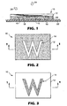
- an article 10 includes a color shifting film 12 and indicia 14 (see FIGS. 2, 3 ) disposed behind the film 12 and viewable through the film 12 for at least some viewing and/or illumination geometries.
- the indicia 14 is made up of or defined by at least a first colored portion 16 and a second colored portion 18.
- portions 16,18 are patterned in complementary fashion so as to define the indicia 14, which in this embodiment is a single letter "W".
- FIG. 1 corresponds roughly to a sectional view taken along axis 1-1 in FIGS. 2-3 , which are drawn to a somewhat smaller scale than FIG. 1 .
- Article 10 also includes an optional adhesive layer 20, which preferably comprises a conventional pressure-sensitive adhesive (PSA), but alternatively can comprise a heat-activated adhesive or other suitable adhesive.
- Adhesive layer 20 secures the article 10 to an optional substrate 22.
- substrate 22 can form part of the article 10.
- substrate 22 can itself comprise a wide variety of different articles, such as a document, sheet of paper, rigid or flexible sign backing, or rigid or flexible window material if some illumination is desired from the back of article 10. To the extent any light is transmitted through the combination of color shifting film 12 and indicia 14, such light can be absorbed, reflected diffusely or specularly, or transmitted by substrate 22.
- the color shifting film 12 has the property of transmitting different wavelengths of light as a function of the angle such light impinges on the film.
- the transmission properties may also be polarization dependent, even at normal incidence.
- film 12 can be a polarizer, a mirror, or a mirror having substantial polarizing properties.
- Preferred films 12 have a multitude of alternating polymer layers arranged into a multitude of unit cells, each unit cell effective to reflect light at a wavelength twice the optical thickness of such unit cell.
- Such films can be made by co-extrusion of two or more polymers forming an interleaved stream of materials. The cast coextruded film can be subsequently thinned and oriented by stretching uniaxially or biaxially to form a finished reflective polarizer or mirror.
- At least one of the polymers is capable of strain-induced birefringence so that the indices of refraction change on stretching.
- the unit cells which can each include two, three, or more individual polymer layers, are typically also arranged to have an optical thickness gradient across the thickness of the film 12 so that a relatively wide spectral band ("reflection band") is reflected by the film. Boundaries of the reflection band are referred to herein as band edges-spectral transitions from high reflectivity (low transmission) to low reflectivity (high transmission) or vice versa. It is also known to tailor the thickness profile of the unit cells to sharpen the band edges.
- preferred polymeric films described in the preceding paragraph have the added benefit of being able to maintain the integrity of their band edges over substantially all incidence angles and regardless of polarization of light, by controlling the out-of-plane (z-index) index of refraction of adjacent layers within the film.
- the difference ⁇ n z , in index of refraction along the z-axis of adjacent polymer layers within a unit cell is less than the maximum index difference in the plane of the film (i.e., ⁇ n x or ⁇ n y ) between such adjacent layers, more preferably less than 0.5 or 0.2 times such maximum in-plane index difference, and can also preferably be substantially zero.
- Suitable films are available from 3M Company (St. Paul, Minnesota, USA) under the designation 3MTM Radiant Light Film.
- Coextruded polymeric films whose layers are not oriented, and thus are substantially isotropic in refractive index, can also be used for the color shifting film.
- Such films are described, for example, in U.S. Patent Nos. 3,801,429 (Schrenk et al. ), 4,162,343 (Wilcox et al. ), and 4,310,584 (Cooper et al. ).
- the first colored portion 16 is patterned to form the foreground of a letter "W", and is disposed behind color shifting film 12. Other letters, symbols, or shapes which convey information are also contemplated.
- portion 16 includes a fluorescent colorant.
- colorant as used herein means any pigment, dye, or other substance or combination of substances used to impart hue or chroma to an article.
- fluorescent refers to the property of emitting light at one wavelength (or band of wavelengths) as a result of the absorption of light at a different (and typically shorter) wavelength (or band of wavelengths).
- the wavelength range of emitted fluorescent light is referred to as an emission band; that of the absorbed light is referred to as an excitation band.
- light in the emission band can be substantially transmitted through the color shifting film at some angles.
- light in the emission band is substantially reflected by the color shifting film (and therefore blocked from reaching the eye of an observer) at other angles.
- light in the excitation band can be blocked from reaching the fluorescent colorant at some angles but transmitted to the fluorescent colorant at other angles.
- Arrows 24,26 shown in FIG. 1 represent a normal-incidence viewing angle and an oblique viewing angle respectively. At one of these angles, color shifting film 12 transmits the fluorescent emission of first colored portion 16, yielding a bright "W" ( FIG. 3 ). At the other angle, color shifting film 12 may substantially block light in the emission band so that the "W" is relatively dark ( FIG. 2 ).
- excitation light passes through the color shifting film 12 before reaching first colored portion 16.
- Some color shifting films 12 can effectively transmit the excitation light only for some directions of incidence and/or only for some polarizations.
- Such selective transmission of excitation light can be used in a specialized procedure to interrogate the article: one light beam having the appropriate angular and/or polarization properties is alternated with another light beam not having those properties, and the visual response (fluorescent emission or lack thereof at a suitable observation angle) is monitored.
- the application may be one in which the article 10 is exposed to light impinging on its front surface from substantially all angles and polarizations-such as is found in typical office environments ⁇ in which case a sufficient amount of light in the excitation band, and having the appropriate angular and/or polarization properties, will be present to produce fluorescence in the portion 16.
- Other color shifting films 12 can effectively transmit excitation light for substantially all or at least a wide range of incidence angles and/or polarizations. For those films, a comparatively greater amount of ambient light will pass through the color shifting film to produce a brighter fluorescent emission.
- a source of light such as a backlight or other lamp, is employed behind the article 10.
- any materials or elements disposed behind portion 16 are simply selected to have an aggregate transmission for light in the excitation band sufficient to produce the desired fluorescent effect in portion 16.
- Article 10 also includes second colored portion 18 disposed behind color shifting film 12.
- portion 18 can be patterned in a complementary fashion to portion 16.
- the unpatterned portion can for instance be printed in a continuous layer to cover the patterned portion in some places and to extend between parts of the patterned portion in other places.
- the patterned portion can be printed on top of the continuous unpatterned portion and the resulting combination laminated to or otherwise placed behind color shifting film 12.
- the patterned portion can be printed to the back side of the color shifting film, and the unpatterned portion can simply be positioned behind that combination.
- Conventional coating processes can be used to apply the colored portion(s) to the film 12, including without limitation flexographic printing techniques.
- the article includes an unpatterned adhesive layer 20, such layer can replace the first or second colored portions 16,18 by inclusion of the appropriate fluorescent and, if desirable, non-fluorescent colorants.
- portion 18 forms a background for the indicia 14.
- portion 18 also includes a fluorescent colorant, but differing from the fluorescent colorant of portion 16 preferably by its emission spectrum. That is, portion 18 preferably fluoresces at a substantially different color than that of portion 16.
- the different emission wavelengths can be coordinated with the properties of the color shifting film 12 such that bright fluorescent colors appear or disappear with changing angle to enhance visibility and contrast of the indicia 14.
- the color shifting film 12 may substantially block fluorescent emission from portion 16 but substantially transmit fluorescent emission from portion 18. This is depicted in FIG. 2 , where stippling is used to indicate a bright colored appearance and non-stippled areas indicate a darkened appearance.
- the color shifting film 12 may process the fluorescent emissions in the opposite sense, resulting in a reverse contrast image of a different color as depicted in FIG. 3 .
- Portions 16,18 can also include non-fluorescent pigments, dyes, inks, or other colorants-i.e., colorants that do not produce fluorescent emission noticeable to an ordinary observer when exposed to expected light levels for the particular application.
- FIGS. 4 & 5 are idealized, simplified composite graphs that depict spectral properties of the first and second colored portions, and of the color shifting film for a particular embodiment.
- the x-axis represents the wavelength of light ⁇ in nanometers (nm), with the visible region extending roughly from 400 to 700 nm.
- Curve 50 ( FIG. 4 ) represents the spectral transmission of color shifting film 12 at nominal incidence, and curve 50' ( FIG. 5 ) represents its transmission at an oblique angle of incidence.
- curves may be for a particular polarization of light, or instead an average over all polarizations.
- the y-axis represents percent transmission, from 0% to 100%.
- the specular reflectivity at a particular wavelength is substantially 100% minus the percent transmission, since absorption in the films is typically much less than 1% for most wavelengths of interest.
- Curves 52 and 54 represent the effective reflectivity (reflectivity plus fluorescent intensity) of colored portions 16, 18 respectively, measured by themselves in the absence of any color shifting film.
- the y-axis represents effective reflectivity in arbitrary units. Curves 52,54 are roughly to scale with respect to each other. However, the relative heights of the curves are not intended to be exact, and all curves are idealized for ease of discussion.
- the color shifting film 12 has a low transmission in a reflectance band bounded by band edges 50a, 50b as shown. Outside the reflectance band, the film has high transmission. At this geometry, therefore, film 12 substantially blocks light associated with colored portion 16 (curve 52) but substantially transmits light associated with colored portion 18 (curve 54). The viewer sees high contrast indicia with a bright background portion of one color and a darkened foreground portion as depicted in FIG. 2 . Note that the film 12 substantially transmits light at shorter wavelengths than the curves 52,54, where excitation bands for the fluorescent colorants would normally lie.
- the reflectance band and associated band edges now labeled 50a' and 50b', have shifted to shorter wavelengths-hence the term color shifting film to describe the accompanying shift in transmitted light.
- light from colored portion 16 (curve 52) is substantially transmitted by the film 12, but light from portion 18 (curve 54) is substantially blocked.
- the viewer again sees high contrast indicia, but now with a darkened background portion and a bright foreground portion as depicted in FIG. 3 .
- the foreground and background portions can both be bright or both be dark.
- band edge 50b' may shift sufficiently to shorter wavelengths such that both foreground and background portions are bright.
- This angular behavior is illustrated in FIG. 5a , where 56 indicates angular ranges where fluorescent emission from first colored portion 16 (curve 52) is substantially visible to the observer, and 58 is analogous for colored portion 18 (curve 54).
- An axis 11 in FIG. 5a represents an axis normal to the article 10.
- portions 16, 18 are arranged as foreground and background of a particular indicia as described above. Additionally, portion 16 can be used (as either a foreground or background) to define one indicia and portion 18 can be used (either as a foreground or background) to define a second independent indicia.
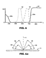
- FIG. 6 is an idealized, simplified composite graph for normal incidence similar to FIG. 4 , but for a different embodiment having different first and second colored portions 16,18, and a different color shifting film 12.
- Curve 60 represents the spectral transmission of color shifting film 12 at normal incidence.
- Curve 60 includes band edges 60a, 60b.
- Curves 62,64 represent the effective reflectivity (as discussed above) of colored portions 16, 18 respectively.
- the overall spectral distributions of curves 62,64 represent substantially different colors.
- the film 12 substantially blocks light associated with colored portions 16,18, so that both are substantially invisible.
- color shifting film 12 (and article 10) in this embodiment have the appearance of a silvery visible mirror since film 12 reflects over substantially the entire visible spectrum.
- the film 12 also has substantial transmission at shorter wavelengths (see band edge 60b) to permit excitation light to pass through to the colored portions.
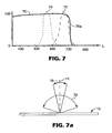
- FIG. 7 is an idealized, simplified composite graph for normal incidence similar to FIG. 6 , but for still another embodiment having different first and second colored portions 16,18, and a different color shifting film 12.
- Curve 70 represents the spectral transmission of color shifting film 12 at normal incidence.
- Curve 70 includes band edge 70a.
- Curves 72,74 represent the effective reflectivity (as discussed above) of colored portions 16, 18 respectively.
- the overall spectral distributions of curves 72,74 represent substantially different colors.
- the film 12 substantially transmits light from both curves 72,74 to yield a high contrast appearance with bright foreground and bright background of different colors.
- the film 12 has the appearance of a substantially clear film, because it has high transmission throughout the visible spectrum.
- Film 12 also transmits light at wavelengths shorter than curves 72,74, where the excitation bands of the fluorescent colorants normally lie.
- band edge 70a shifts towards the blue (shorter wavelengths) with increasing angle.
- FIG. 7a depicts the angular behavior graphically: 76 indicates angular ranges where fluorescent emission from first colored portion 16 (curve 72) is substantially visible to the observer, and 78 is analogous for colored portion 18 (curve 74).
- FIG. 8 is yet another idealized, simplified composite graph for normal incidence similar to FIG. 7 , but for still another embodiment having different first and second colored portions 16,18, and a different color shifting film 12.
- Curve 80 represents the spectral transmission of color shifting film 12 at normal incidence.
- Curve 80 includes band edges 80a, 80b, 80c.
- Curves 82,84 represent the effective reflectivity (as discussed above) of colored portions 16, 18 respectively.
- the overall spectral distributions of curves 82,84 represent substantially different colors.
- the film 12 substantially transmits light from curves 82 but substantially blocks light from curve 84 to yield a high contrast appearance with bright foreground and dark background. Note that film 12 transmits light at relatively short wavelengths (see band edge 80c), where the excitation bands of the fluorescent colorants would lie.
- FIG. 8a demonstrates how an observer sees the bright fluorescence from first colored portion 16 over angular range 86 and the bright fluorescence from second colored portion 18 over angular range 88.
- suitable articles 10 can include additional layers and features.
- color shifting film 12 can include one or more regions that have been embossed with heat and/or pressure.
- the embossed regions are thinner than non-embossed neighboring regions and therefore have spectral transmission and reflection features that are blue-shifted relative to corresponding features of the non-embossed regions.
- the embossed regions can take the form of indicia in addition to the indicia 14 discussed above.
- the color shifting film 12 can contain or carry a microstructured relief pattern suitable for producing conventional holographic images. Such images can be used to obscure the indicia 14 at selected geometries.
- the relief pattern can be formed using known holographic embossing techniques into a suitable skin layer or coating on top of the color shifting film.
- the relief pattern can alternately be incorporated into a separate transparent sheet that is laminated to the color shifting film.
- a separate transparent sheet is preferably polymeric for ease of manufacture and for article integrity over operating temperature ranges.
- additional graphics, symbols, or other indicia in addition to indicia 14 discussed above can be applied to the article 10 by conventional printing onto color shifting film 12 or onto additional layer(s) laminated to film 12.
- a representative article was constructed using the following component materials: 3M brand Radiant Color Film CM590 for color shifting film 12; Akzo Nobel AGBP 1804 orange fluorescent dye for colored portion 16; and Akzo Nobel AGBP0802 green fluorescent dye for colored portion 18.
- the different dyes were applied by hand to one side (designated the "back" side) of the color shifting film in complementary fashion to form a foreground (portion 16) and background (portion 18) of the word "HAPPY".
- a water-based primer (Akzo Nobel primer type WVL 02002) was applied to the back of film 12 to promote adhesion of the dyes to the film. No adhesive layer 20 was used. The dyes were then allowed to dry.
- the resulting coated film was flexible and had an overall thickness of: about 1.9 mils (50 ⁇ m) for the film 12 by itself; variable from about 2.1 to 7 mils (about 50 to 180 ⁇ m) on average for the film plus dye in the foreground regions; and variable from about 2.6 to 9 mils (about 65 to 230 ⁇ m) on average for the film plus dye in the background regions.
- Color nonuniformities varying from light green to nearly black were observed in the background portion. Lesser nonunifomities (different shades of orange) were observed from one letter to the next in the foreground portion. The nonuniformities appeared to be due to thickness nonuniformities in the dried dyes.
- the article was placed back side down onto a sheet of white paper under ordinary office illumination.
- green fluorescence was observed in regions of the background and orange fluorescence was observed at differing brightness levels in the foreground letters.
- a first angle was reached where the orange fluorescence could not be seen but some green fluorescence could be seen.
- a second angle was reached where substantially no orange or green fluorescence could be seen.
- a third very shallow observation angle about 80 degrees relative to the normal
- the green fluorescence could still not be seen but the orange fluorescence was observed to be quite bright and quite uniform from one letter to the next.
- FIG. 9 plots the measured percent transmission versus wavelength.
- Curve 90 was measured with unpolarized light at normal incidence to the film.
- Curve 92 is an average of p-polarized light and s-polarized light (i.e., light linearly polarized in the plane of incidence and perpendicular to the plane of incidence respectively) for an angle of 60 degrees from the normal direction. Note the wavelength shift of the reflection band and the good maintenance of the sharp band edges.
- FIG. 10 is data measured using a Perkin Elmer Model LSB50 Luminescence Spectrophotometer for the orange fluorescent dye.
- Curve 100 is the emission band and curve 102 is the excitation band for the dye. The two curves are plotted against relative response (in arbitrary units). Note that the excitation band 102 exists not only in the ultraviolet region but extends well into the visible region. In comparing FIGS. 9 and 10 note also that the CM590 film substantially transmits light in the excitation band 102 at normal angles and at oblique angles.
- FIG. 11 is data measured using a Perkin Elmer Model LSB50 Luminescence Spectrophotometer for the green fluorescent dye. Curve 110 is the emission band and curve 112 is the excitation band for the dye.
- the two curves are plotted against relative response (in arbitrary units).
- the excitation band 112 exists not only in the ultraviolet region but extends well into the visible region, and that the CM590 film substantially transmits light in the excitation band 102 at normal angles and at oblique angles.
- the normal incidence curve 90 for the color shifting film substantially transmits light in the emission band 110 of the green fluorescent dye, and also transmits light in the emission band 100 of the orange fluorescent dye but has a sharp band edge that appears to overlap with a substantial portion of emission band 100.
- curve 92 has poor transmission in the green emission band 110 and poor transmission in the orange emission band 100.
- the reflection band moves to even shorter wavelengths with even higher incidence angles, the right band edge of the reflection band crosses over the bulk of the emission band 100 to permit orange fluorescence to again be seen.
Abstract
Description
- The present invention relates generally to films and other articles that incorporate information whose appearance is highly dependent upon viewing angle.
- Films that incorporate directional images-images that are viewable at some viewing geometries and not others-are generally known.
U.S. Patent 6,024,455 (O'Neill et al. ), for example, discloses reflective articles in which a multilayer film covers a patterned retroreflective layer. The patterned retroreflective layer can include an indicia layer having patterned regions comprising conventional inks, dyes, or other substances which are substantially opaque to some wavelengths but transparent to others. Such films, however, require specialized lighting arrangements for optimal viewing. -
PCT Publication WO 99/36258 (Weber et al. - Examples of optical security articles are provided by
US 5, 310,222 andGB 2 347646 - In the search for always different and visually impressive product constructions, applicants have discovered new and useful combinations of color shifting films and fluorescent colorants. The invention corresponds to the article defined in
claim 1 of the appended claims. For example, applicants describe herein embodiments in which at least a first and second colored portion are disposed behind a color shifting film, such portions comprising respectively first and second different fluorescent colorants. The first and second colored portion define indicia. The properties of the color shifting film and of the first and second fluorescent colorants can be selected so that at a first angle fluorescent emission from only the first colorant is visible through the film. At a second angle, fluorescent emission from the second colorant is visible through the film. If fluorescent emission from the first colorant is not visible through the film at the second angle, a third angle may exist at which fluorescent emission from both colorants are visible through the film. A fourth angle may also exist at which fluorescent emission from neither colorant is visible through the film. By arranging the first and second colored portions as a foreground and background of the indicia, these properties can produce highly visible indicia with dramatic contrast changes as a function of angle. -
-
Fig. 1 is a sectional view of an article having a color shifting film and a first and second colored portion disposed behind the film which form indicia, the article being adhered to a substrate; -
FIG. 2 is a front view of the article ofFIG. 1 from one viewing angle, where speckling is used to indicate a bright fluorescent color; -
FIG. 3 is a front view of the article ofFIG. 1 from another viewing angle, where speckling is used to indicate a bright fluorescent color; -
FIG. 4 is an idealized and simplified composite graph depicting spectral properties of the first and second colored portions, and of the color shifting film at one viewing angle; -
FIG. 5 is an idealized and simplified composite graph depicting spectral properties of the first and second colored portions, and of the color shifting film at another viewing angle; -
FIGS. 6 ,7 , and8 are idealized and simplified composite graphs depicting spectral properties of the first and second colored portions, and of the color shifting film at one viewing angle, for three different embodiments; - F1GS. 5a, 6a, 7a, and 8a are side views of the embodiments of
FIGS. 4 & 5 ,FIG. 6 ,FIG. 7 , andFIG. 8 respectively showing idealized viewing ranges for the different fluorescent colorants; -
FIG. 9 is a graph of measured spectral transmission of a particular color shifting film at normal (0 degree) incidence and at 60 degrees incidence; -
FIG. 10 is a graph of measured spectral properties of a particular orange fluorescent dye; and -
FIG. 11 is a graph of measured spectral properties of a particular green fluorescent dye. - In the figures, like reference numerals indicate like elements.
- In
FIG. 1 , anarticle 10 includes acolor shifting film 12 and indicia 14 (seeFIGS. 2, 3 ) disposed behind thefilm 12 and viewable through thefilm 12 for at least some viewing and/or illumination geometries. Theindicia 14 is made up of or defined by at least a first coloredportion 16 and a second coloredportion 18. As shown best inFIGS. 1-3 ,portions indicia 14, which in this embodiment is a single letter "W". Note thatFIG. 1 corresponds roughly to a sectional view taken along axis 1-1 inFIGS. 2-3 , which are drawn to a somewhat smaller scale thanFIG. 1 .Article 10 also includes an optionaladhesive layer 20, which preferably comprises a conventional pressure-sensitive adhesive (PSA), but alternatively can comprise a heat-activated adhesive or other suitable adhesive.Adhesive layer 20 secures thearticle 10 to anoptional substrate 22. If desired,substrate 22 can form part of thearticle 10. Depending upon the intended use of thearticle 10,substrate 22 can itself comprise a wide variety of different articles, such as a document, sheet of paper, rigid or flexible sign backing, or rigid or flexible window material if some illumination is desired from the back ofarticle 10. To the extent any light is transmitted through the combination ofcolor shifting film 12 andindicia 14, such light can be absorbed, reflected diffusely or specularly, or transmitted bysubstrate 22. - The color shifting
film 12 has the property of transmitting different wavelengths of light as a function of the angle such light impinges on the film. The transmission properties may also be polarization dependent, even at normal incidence. In this regard,film 12 can be a polarizer, a mirror, or a mirror having substantial polarizing properties. Preferredfilms 12 have a multitude of alternating polymer layers arranged into a multitude of unit cells, each unit cell effective to reflect light at a wavelength twice the optical thickness of such unit cell. Such films can be made by co-extrusion of two or more polymers forming an interleaved stream of materials. The cast coextruded film can be subsequently thinned and oriented by stretching uniaxially or biaxially to form a finished reflective polarizer or mirror. Preferably, at least one of the polymers is capable of strain-induced birefringence so that the indices of refraction change on stretching. The unit cells, which can each include two, three, or more individual polymer layers, are typically also arranged to have an optical thickness gradient across the thickness of thefilm 12 so that a relatively wide spectral band ("reflection band") is reflected by the film. Boundaries of the reflection band are referred to herein as band edges-spectral transitions from high reflectivity (low transmission) to low reflectivity (high transmission) or vice versa. It is also known to tailor the thickness profile of the unit cells to sharpen the band edges. These and other aspects of suitable color shifting films are described in one or more ofU.S. Patent Nos. 5,882,774 (Jonza et al. );6,024,455 (O'Neill et al. ); andU.S. Patent Application No. 09/006,591 entitled "Color Shifting Film" (Weber et al.), filed Jan. 13, 1998. Reference is also made toU.S. Patent Nos. 5,103,337 (Schrenk et al. ) (reissued asRe. 34,605 ) and5,360,659 (Arends et al. ) for discussions of unit cells having more than two individual layers and/or more than two unique polymer materials. - Conventional inorganic multilayer films-made for example by vacuum deposition of two inorganic dielectric materials sequentially in a multitude of layers on a glass or other suitable substrate, or alternating layers of inorganic materials and organic polymers (see, e.g.,
U.S. Patent Nos. 5,440,446 (Shaw et al. ),5,877,895 (Shaw et al. ), and6,010,751 (Shaw et al. ))―can also be used as thecolor shifting film 12. Compared to these alternative multilayer films, preferred polymeric films described in the preceding paragraph have the added benefit of being able to maintain the integrity of their band edges over substantially all incidence angles and regardless of polarization of light, by controlling the out-of-plane (z-index) index of refraction of adjacent layers within the film. Preferably, the difference Δnz, in index of refraction along the z-axis of adjacent polymer layers within a unit cell is less than the maximum index difference in the plane of the film (i.e., Δnx or Δny) between such adjacent layers, more preferably less than 0.5 or 0.2 times such maximum in-plane index difference, and can also preferably be substantially zero. These conditions help maintain the shape of the band edge even as the reflection band shifts in wavelength or color with changing incidence angle, which corresponds visually to high color saturation over a wide range of incidence angles. Suitable films are available from 3M Company (St. Paul, Minnesota, USA) under the designation 3M™ Radiant Light Film. - Coextruded polymeric films whose layers are not oriented, and thus are substantially isotropic in refractive index, can also be used for the color shifting film. Such films are described, for example, in
U.S. Patent Nos. 3,801,429 (Schrenk et al. ),4,162,343 (Wilcox et al. ), and4,310,584 (Cooper et al. ). - The first
colored portion 16 is patterned to form the foreground of a letter "W", and is disposed behindcolor shifting film 12. Other letters, symbols, or shapes which convey information are also contemplated. Importantly,portion 16 includes a fluorescent colorant. The term "colorant" as used herein means any pigment, dye, or other substance or combination of substances used to impart hue or chroma to an article. The term "fluorescent" refers to the property of emitting light at one wavelength (or band of wavelengths) as a result of the absorption of light at a different (and typically shorter) wavelength (or band of wavelengths). The wavelength range of emitted fluorescent light is referred to as an emission band; that of the absorbed light is referred to as an excitation band. By proper selection of fluorescent colorant and color shifting film, light in the emission band can be substantially transmitted through the color shifting film at some angles. In some embodiments light in the emission band is substantially reflected by the color shifting film (and therefore blocked from reaching the eye of an observer) at other angles. Additionally or alternatively, if a highly directional light source is used, light in the excitation band can be blocked from reaching the fluorescent colorant at some angles but transmitted to the fluorescent colorant at other angles.Arrows FIG. 1 represent a normal-incidence viewing angle and an oblique viewing angle respectively. At one of these angles,color shifting film 12 transmits the fluorescent emission of firstcolored portion 16, yielding a bright "W" (FIG. 3 ). At the other angle,color shifting film 12 may substantially block light in the emission band so that the "W" is relatively dark (FIG. 2 ). - The preceding discussion of course assumes that the fluorescent colorant in
colored portion 16 is able to be excited by absorption of light in the excitation band. Such excitation can be achieved in a number of ways depending upon the intended application. - In some applications no significant amount of light is generated from behind the
article 10. In those cases excitation light passes through thecolor shifting film 12 before reaching firstcolored portion 16. Somecolor shifting films 12 can effectively transmit the excitation light only for some directions of incidence and/or only for some polarizations. Such selective transmission of excitation light can be used in a specialized procedure to interrogate the article: one light beam having the appropriate angular and/or polarization properties is alternated with another light beam not having those properties, and the visual response (fluorescent emission or lack thereof at a suitable observation angle) is monitored. Alternatively, the application may be one in which thearticle 10 is exposed to light impinging on its front surface from substantially all angles and polarizations-such as is found in typical office environments―in which case a sufficient amount of light in the excitation band, and having the appropriate angular and/or polarization properties, will be present to produce fluorescence in theportion 16. Othercolor shifting films 12 can effectively transmit excitation light for substantially all or at least a wide range of incidence angles and/or polarizations. For those films, a comparatively greater amount of ambient light will pass through the color shifting film to produce a brighter fluorescent emission. - In some applications a source of light, such as a backlight or other lamp, is employed behind the
article 10. In those cases any materials or elements disposed behindportion 16 are simply selected to have an aggregate transmission for light in the excitation band sufficient to produce the desired fluorescent effect inportion 16. -
Article 10 also includes secondcolored portion 18 disposed behindcolor shifting film 12. As shown inFIG. 1 ,portion 18 can be patterned in a complementary fashion toportion 16. Alternatively, for simplicity of manufacturing, only one ofportions color shifting film 12. In still another approach the patterned portion can be printed to the back side of the color shifting film, and the unpatterned portion can simply be positioned behind that combination. Conventional coating processes can be used to apply the colored portion(s) to thefilm 12, including without limitation flexographic printing techniques. - If the article includes an
unpatterned adhesive layer 20, such layer can replace the first or secondcolored portions - As shown in
FIGS. 1-3 ,portion 18 forms a background for theindicia 14. Importantly,portion 18 also includes a fluorescent colorant, but differing from the fluorescent colorant ofportion 16 preferably by its emission spectrum. That is,portion 18 preferably fluoresces at a substantially different color than that ofportion 16. The different emission wavelengths can be coordinated with the properties of thecolor shifting film 12 such that bright fluorescent colors appear or disappear with changing angle to enhance visibility and contrast of theindicia 14. For example, at one viewing angle thecolor shifting film 12 may substantially block fluorescent emission fromportion 16 but substantially transmit fluorescent emission fromportion 18. This is depicted inFIG. 2 , where stippling is used to indicate a bright colored appearance and non-stippled areas indicate a darkened appearance. At another angle thecolor shifting film 12 may process the fluorescent emissions in the opposite sense, resulting in a reverse contrast image of a different color as depicted inFIG. 3 . -
Portions -
FIGS. 4 & 5 are idealized, simplified composite graphs that depict spectral properties of the first and second colored portions, and of the color shifting film for a particular embodiment. For all curves shown, the x-axis represents the wavelength of light λ in nanometers (nm), with the visible region extending roughly from 400 to 700 nm. Curve 50 (FIG. 4 ) represents the spectral transmission ofcolor shifting film 12 at nominal incidence, and curve 50' (FIG. 5 ) represents its transmission at an oblique angle of incidence. These curves may be for a particular polarization of light, or instead an average over all polarizations. For these curves, the y-axis represents percent transmission, from 0% to 100%. If thecolor shifting film 12 comprises the preferred polymeric multilayer films described above, then the specular reflectivity at a particular wavelength is substantially 100% minus the percent transmission, since absorption in the films is typically much less than 1% for most wavelengths of interest.Curves portions curves Curves - At normal incidence (
FIG. 4 ), thecolor shifting film 12 has a low transmission in a reflectance band bounded byband edges film 12 substantially blocks light associated with colored portion 16 (curve 52) but substantially transmits light associated with colored portion 18 (curve 54). The viewer sees high contrast indicia with a bright background portion of one color and a darkened foreground portion as depicted inFIG. 2 . Note that thefilm 12 substantially transmits light at shorter wavelengths than thecurves - At a high angle of incidence (
FIG. 5 ), the reflectance band and associated band edges, now labeled 50a' and 50b', have shifted to shorter wavelengths-hence the term color shifting film to describe the accompanying shift in transmitted light. At this geometry, light from colored portion 16 (curve 52) is substantially transmitted by thefilm 12, but light from portion 18 (curve 54) is substantially blocked. The viewer again sees high contrast indicia, but now with a darkened background portion and a bright foreground portion as depicted inFIG. 3 . Depending upon the spectral width of the reflectance band and the spacing and width ofcurves FIGS. 4 and 5 the foreground and background portions can both be bright or both be dark. At angles greater than that ofFIG. 5 ,band edge 50b' may shift sufficiently to shorter wavelengths such that both foreground and background portions are bright. This angular behavior is illustrated inFIG. 5a , where 56 indicates angular ranges where fluorescent emission from first colored portion 16 (curve 52) is substantially visible to the observer, and 58 is analogous for colored portion 18 (curve 54). Anaxis 11 inFIG. 5a represents an axis normal to thearticle 10. - For maximum contrast shift,
colored portions portion 16 can be used (as either a foreground or background) to define one indicia andportion 18 can be used (either as a foreground or background) to define a second independent indicia. -
FIG. 6 is an idealized, simplified composite graph for normal incidence similar toFIG. 4 , but for a different embodiment having different first and secondcolored portions color shifting film 12.Curve 60 represents the spectral transmission ofcolor shifting film 12 at normal incidence.Curve 60 includesband edges Curves portions curves film 12 substantially blocks light associated withcolored portions film 12 reflects over substantially the entire visible spectrum. Thefilm 12 also has substantial transmission at shorter wavelengths (seeband edge 60b) to permit excitation light to pass through to the colored portions. - At progressively higher observation angles the blue shift of
band edge 60a allows first the foreground (curve 62) and then the background (curve 64) to appear bright to the viewer. Thus, thearticle 10 which appears substantially mirror-like at normal viewing angles revealsindicia 14 with changing contrast and color at higher observation angles. The angular behavior is illustrated inFIG. 6a , where 66 indicates angular ranges where fluorescent emission from first colored portion 16 (curve 62) is substantially visible to the observer, and 68 is analogous for colored portion 18 (curve 64). -
FIG. 7 is an idealized, simplified composite graph for normal incidence similar toFIG. 6 , but for still another embodiment having different first and secondcolored portions color shifting film 12.Curve 70 represents the spectral transmission ofcolor shifting film 12 at normal incidence.Curve 70 includesband edge 70a.Curves portions curves film 12 substantially transmits light from bothcurves film 12 has the appearance of a substantially clear film, because it has high transmission throughout the visible spectrum.Film 12 also transmits light at wavelengths shorter thancurves - For oblique angle observation,
band edge 70a shifts towards the blue (shorter wavelengths) with increasing angle. First, light from colored portion 16 (curve 72) becomes blocked byfilm 12, followed by light from colored portion 18 (curve 74). Again the viewer seesindicia 14 in high contrast with changing bright or dark colors as a function of angle.FIG. 7a depicts the angular behavior graphically: 76 indicates angular ranges where fluorescent emission from first colored portion 16 (curve 72) is substantially visible to the observer, and 78 is analogous for colored portion 18 (curve 74). -
FIG. 8 is yet another idealized, simplified composite graph for normal incidence similar toFIG. 7 , but for still another embodiment having different first and secondcolored portions color shifting film 12.Curve 80 represents the spectral transmission ofcolor shifting film 12 at normal incidence.Curve 80 includesband edges Curves portions curves film 12 substantially transmits light fromcurves 82 but substantially blocks light fromcurve 84 to yield a high contrast appearance with bright foreground and dark background. Note thatfilm 12 transmits light at relatively short wavelengths (seeband edge 80c), where the excitation bands of the fluorescent colorants would lie. - For oblique angle observation, the band edges shift towards the blue (shorter wavelengths) with increasing angle. By movement of
band edges curve 84 is substantially transmitted and light fromforeground curve 82 becomes blocked by the color shifting film.FIG. 8a demonstrates how an observer sees the bright fluorescence from firstcolored portion 16 overangular range 86 and the bright fluorescence from secondcolored portion 18 overangular range 88. - In general,
suitable articles 10 can include additional layers and features. For example,color shifting film 12 can include one or more regions that have been embossed with heat and/or pressure. The embossed regions are thinner than non-embossed neighboring regions and therefore have spectral transmission and reflection features that are blue-shifted relative to corresponding features of the non-embossed regions. The embossed regions can take the form of indicia in addition to theindicia 14 discussed above. As another example, thecolor shifting film 12 can contain or carry a microstructured relief pattern suitable for producing conventional holographic images. Such images can be used to obscure theindicia 14 at selected geometries. The relief pattern can be formed using known holographic embossing techniques into a suitable skin layer or coating on top of the color shifting film. The relief pattern can alternately be incorporated into a separate transparent sheet that is laminated to the color shifting film. Reference is made generally toU.S. Pat. 5,656,360 (Faykish et al. ). Such a separate transparent sheet is preferably polymeric for ease of manufacture and for article integrity over operating temperature ranges. As yet another example, additional graphics, symbols, or other indicia in addition toindicia 14 discussed above can be applied to thearticle 10 by conventional printing ontocolor shifting film 12 or onto additional layer(s) laminated to film 12. - A representative article was constructed using the following component materials: 3M brand Radiant Color Film CM590 for
color shifting film 12; Akzo Nobel AGBP 1804 orange fluorescent dye forcolored portion 16; and Akzo Nobel AGBP0802 green fluorescent dye forcolored portion 18. The different dyes were applied by hand to one side (designated the "back" side) of the color shifting film in complementary fashion to form a foreground (portion 16) and background (portion 18) of the word "HAPPY". Prior to application of the dyes to thefilm 12, a water-based primer (Akzo Nobel primer type WVL 02002) was applied to the back offilm 12 to promote adhesion of the dyes to the film. Noadhesive layer 20 was used. The dyes were then allowed to dry. The resulting coated film was flexible and had an overall thickness of: about 1.9 mils (50 µm) for thefilm 12 by itself; variable from about 2.1 to 7 mils (about 50 to 180 µm) on average for the film plus dye in the foreground regions; and variable from about 2.6 to 9 mils (about 65 to 230 µm) on average for the film plus dye in the background regions. Color nonuniformities varying from light green to nearly black were observed in the background portion. Lesser nonunifomities (different shades of orange) were observed from one letter to the next in the foreground portion. The nonuniformities appeared to be due to thickness nonuniformities in the dried dyes. - The article was placed back side down onto a sheet of white paper under ordinary office illumination. When viewed from the front at near normal incidence, green fluorescence was observed in regions of the background and orange fluorescence was observed at differing brightness levels in the foreground letters. As the viewing angle with respect to the normal was steadily increased, a first angle was reached where the orange fluorescence could not be seen but some green fluorescence could be seen. Next, a second angle was reached where substantially no orange or green fluorescence could be seen. Finally, at a third very shallow observation angle (about 80 degrees relative to the normal), the green fluorescence could still not be seen but the orange fluorescence was observed to be quite bright and quite uniform from one letter to the next.
- The spectral properties of the color shifting film and of the orange and green fluorescent dyes used in the example were measured to explain the observed angular dependence of the image contrast. The transmission of a spare (uncoated) piece of the CM590 film was measured using a Perkin Elmer Lambda 19 RSA-PE19S spectrometer.
FIG. 9 plots the measured percent transmission versus wavelength.Curve 90 was measured with unpolarized light at normal incidence to the film.Curve 92 is an average of p-polarized light and s-polarized light (i.e., light linearly polarized in the plane of incidence and perpendicular to the plane of incidence respectively) for an angle of 60 degrees from the normal direction. Note the wavelength shift of the reflection band and the good maintenance of the sharp band edges.FIG. 10 is data measured using a Perkin Elmer Model LSB50 Luminescence Spectrophotometer for the orange fluorescent dye.Curve 100 is the emission band andcurve 102 is the excitation band for the dye. The two curves are plotted against relative response (in arbitrary units). Note that theexcitation band 102 exists not only in the ultraviolet region but extends well into the visible region. In comparingFIGS. 9 and10 note also that the CM590 film substantially transmits light in theexcitation band 102 at normal angles and at oblique angles.FIG. 11 is data measured using a Perkin Elmer Model LSB50 Luminescence Spectrophotometer for the green fluorescent dye.Curve 110 is the emission band andcurve 112 is the excitation band for the dye. The two curves are plotted against relative response (in arbitrary units). Note again that theexcitation band 112 exists not only in the ultraviolet region but extends well into the visible region, and that the CM590 film substantially transmits light in theexcitation band 102 at normal angles and at oblique angles. Thenormal incidence curve 90 for the color shifting film substantially transmits light in theemission band 110 of the green fluorescent dye, and also transmits light in theemission band 100 of the orange fluorescent dye but has a sharp band edge that appears to overlap with a substantial portion ofemission band 100. At the 60 degree incidence angle,curve 92 has poor transmission in thegreen emission band 110 and poor transmission in theorange emission band 100. As the reflection band moves to even shorter wavelengths with even higher incidence angles, the right band edge of the reflection band crosses over the bulk of theemission band 100 to permit orange fluorescence to again be seen.
Claims (16)
- An article, comprising:a color shifting film (12) that transmits different wavelength of light as a function of the angle such light impinges on the film; andan indicia layer disposed behind the color shifting film;wherein the indicia layer includes at least a first (16) and second (18) colored portion arranged as a foreground and a background of the indicia, the first colored portion comprising a first fluorescent colorant and the second colored portion comprising a second fluorescent colorant different from the first fluorescent colorant; andwherein the first and second fluorescent colorants have first and second emission bands respectively, and wherein at a first viewing angle the color shifting film substantially blocks transmission of light so that fluorescent emission from only in the first emission band and substantially transmits light the second fluorescent colorant is visible through the color shifting film in the second emission band
- The article of claim 1, wherein at a second viewing angle the color shifting film substantially transmits light in the first emission band and substantially blocks light in the second emission band.
- The article of claim 1, wherein at a second viewing angle the color shifting film substantially transmits light in the first and second emission bands.
- The article of claim 1, wherein at least the first colored portion is printed on the color shifting film.
- The article of claim 1, wherein at least the second colored portion is printed on the color shifting film.
- The article of claim 5, wherein the first colored portion is also printed on the color shifting film, and the second colored portion is printed substantially continuously to extend over the first colored portion.
- The article of claim 1, further comprising an adhesive layer.
- The article of claim 7, wherein the adhesive layer is disposed to permit attachment of the article to a substrate.
- The article of claim 7, wherein the adhesive layer comprises one of the first and second colored portions.
- The article of claim 1, wherein the foreground comprises the first colored portion and the background comprises the second colored portion.
- The article of claim 1, wherein the background comprises the first colored portion and the foreground comprises the second colored portion.
- The article of claim 1, wherein the color shifting film is selected from the group consisting of a polarizer and a mirror.
- The article of claim 1, further comprising a substantially white diffuse surface disposed behind the indicia.
- The article of claim 1, wherein the first fluorescent colorant has an excitation band, and wherein the color shifting film substantially blocks transmission of light in the excitation band at a first angle and substantially transmits light in the excitation band at a second angle.
- The article of claim 1, wherein the second fluorescent colorant has an excitation band, and wherein the color shifting film substantially blocks transmission of light in the excitation band at a first angle and substantially transmits light in the excitation band at a second angle.
- The article of claim 1, further comprising additional indicia formed by at least one element selected from the group consisting of an embossed region of the color shifting film, a holographic element, and printed information.
Applications Claiming Priority (3)
| Application Number | Priority Date | Filing Date | Title |
|---|---|---|---|
| US785652 | 2001-02-16 | ||
| US09/785,652 US6506480B2 (en) | 2001-02-16 | 2001-02-16 | Color shifting film with a plurality of fluorescent colorants |
| PCT/US2001/022320 WO2002067023A2 (en) | 2001-02-16 | 2001-07-16 | Color shifting film with a plurality of fluorescent colorants |
Publications (2)
| Publication Number | Publication Date |
|---|---|
| EP1402290A2 EP1402290A2 (en) | 2004-03-31 |
| EP1402290B1 true EP1402290B1 (en) | 2011-01-26 |
Family
ID=25136193
Family Applications (1)
| Application Number | Title | Priority Date | Filing Date |
|---|---|---|---|
| EP01958962A Expired - Lifetime EP1402290B1 (en) | 2001-02-16 | 2001-07-16 | Color shifting film with a plurality of fluorescent colorants |
Country Status (11)
| Country | Link |
|---|---|
| US (1) | US6506480B2 (en) |
| EP (1) | EP1402290B1 (en) |
| JP (1) | JP2004525406A (en) |
| CN (1) | CN1262853C (en) |
| AT (1) | ATE497183T1 (en) |
| AU (1) | AU2001280567B2 (en) |
| BR (1) | BR0116881A (en) |
| CA (1) | CA2438061A1 (en) |
| DE (1) | DE60143968D1 (en) |
| TW (1) | TW574103B (en) |
| WO (1) | WO2002067023A2 (en) |
Families Citing this family (35)
| Publication number | Priority date | Publication date | Assignee | Title |
|---|---|---|---|---|
| US6531230B1 (en) * | 1998-01-13 | 2003-03-11 | 3M Innovative Properties Company | Color shifting film |
| US6731416B2 (en) * | 2000-12-14 | 2004-05-04 | Ttools, Llc | Holographic privacy filter for display devices |
| US7245072B2 (en) * | 2003-01-27 | 2007-07-17 | 3M Innovative Properties Company | Phosphor based light sources having a polymeric long pass reflector |
| US7118438B2 (en) * | 2003-01-27 | 2006-10-10 | 3M Innovative Properties Company | Methods of making phosphor based light sources having an interference reflector |
| KR20050103200A (en) * | 2003-01-27 | 2005-10-27 | 쓰리엠 이노베이티브 프로퍼티즈 컴파니 | Phosphor based light source component and method of making |
| US7091661B2 (en) * | 2003-01-27 | 2006-08-15 | 3M Innovative Properties Company | Phosphor based light sources having a reflective polarizer |
| US20040145289A1 (en) * | 2003-01-27 | 2004-07-29 | 3M Innovative Properties Company | Phosphor based light sources having a non-planar short pass reflector and method of making |
| US20040145312A1 (en) * | 2003-01-27 | 2004-07-29 | 3M Innovative Properties Company | Phosphor based light source having a flexible short pass reflector |
| US7312560B2 (en) * | 2003-01-27 | 2007-12-25 | 3M Innovative Properties | Phosphor based light sources having a non-planar long pass reflector and method of making |
| US7091653B2 (en) | 2003-01-27 | 2006-08-15 | 3M Innovative Properties Company | Phosphor based light sources having a non-planar long pass reflector |
| US7157839B2 (en) | 2003-01-27 | 2007-01-02 | 3M Innovative Properties Company | Phosphor based light sources utilizing total internal reflection |
| US7455877B2 (en) * | 2003-11-25 | 2008-11-25 | Vin Mark Security Services, Llc | Vehicle identification marking system |
| US7566473B2 (en) * | 2003-11-25 | 2009-07-28 | Vin Mark Security Services, Llc | Vehicle identification marking system |
| US7457037B2 (en) * | 2004-09-27 | 2008-11-25 | Corning Incorporated | Transparent polarizing optical products and fabrication thereof |
| US20060234014A1 (en) * | 2005-04-14 | 2006-10-19 | Liu Yaoqi J | Patterned adhesives for tamper evident feature |
| US20060234040A1 (en) * | 2005-04-14 | 2006-10-19 | Liu Yaoqi J | Patterned adhesives for color shifting effect |
| US7565751B2 (en) * | 2006-10-16 | 2009-07-28 | The Stanley Works | Measuring device with fluorescent translucent material |
| US7547105B2 (en) * | 2007-07-16 | 2009-06-16 | 3M Innovative Properties Company | Prismatic retroreflective article with cross-linked image layer and method of making same |
| TW200946814A (en) * | 2008-01-08 | 2009-11-16 | Koninkl Philips Electronics Nv | Light output device |
| DE102008036402B3 (en) * | 2008-08-01 | 2009-09-17 | Bundesdruckerei Gmbh | Gonioluminescent security element and process for its preparation |
| KR102103414B1 (en) * | 2008-12-08 | 2020-04-23 | 쓰리엠 이노베이티브 프로퍼티즈 컴파니 | Protective overlay bearing a graphic and retroreflective articles comprising the overlay |
| JP2012511177A (en) * | 2008-12-08 | 2012-05-17 | スリーエム イノベイティブ プロパティズ カンパニー | Prism-like retroreflective article having figure and method for producing the same |
| JP5746045B2 (en) | 2008-12-22 | 2015-07-08 | スリーエム イノベイティブ プロパティズ カンパニー | Internal pattern forming multilayer optical film having a plurality of birefringent layers |
| CA2656506A1 (en) * | 2009-02-27 | 2010-08-27 | Bank Of Canada | Security device |
| EP3396424A3 (en) * | 2009-12-17 | 2018-12-26 | Apple Inc. | Dichroic glass for cosmetic appeal in an electronic device |
| KR102295559B1 (en) | 2013-07-15 | 2021-08-30 | 쓰리엠 이노베이티브 프로퍼티즈 캄파니 | Respirator having optically active exhalation valve |
| KR20150083278A (en) * | 2014-01-09 | 2015-07-17 | 삼성전기주식회사 | Multilayered substrate and method of manufacturing the same |
| CA2932080C (en) * | 2015-06-10 | 2023-11-14 | Nanotech Security Corp. | Optical devices, and their use for security and authentication |
| GB2547717B (en) * | 2016-02-29 | 2020-09-16 | De La Rue Int Ltd | Security elements and security documents |
| KR20190018550A (en) * | 2016-07-12 | 2019-02-22 | 쓰리엠 이노베이티브 프로퍼티즈 컴파니 | Optical stack |
| US10914878B2 (en) * | 2016-12-20 | 2021-02-09 | 3M Innovative Properties Company | Multilayer film including hidden fluorescent features |
| CN107499013A (en) * | 2017-09-26 | 2017-12-22 | 厦门汉盾光学科技有限公司 | A kind of security article and preparation method thereof |
| US11726245B2 (en) * | 2017-10-02 | 2023-08-15 | 3M Innovative Properties Company | Partial reflector having stack of polymer layers for correcting color shift |
| EP3824111B1 (en) * | 2018-07-17 | 2023-08-30 | 3M Innovative Properties Company | Conformable color shifting laminates |
| CN110749947B (en) * | 2019-10-29 | 2021-06-01 | 浙江龙游道明光学有限公司 | Method for manufacturing high-visual-contrast reflective film |
Citations (1)
| Publication number | Priority date | Publication date | Assignee | Title |
|---|---|---|---|---|
| GB2347646A (en) * | 1999-03-12 | 2000-09-13 | Rue De Int Ltd | Security element comprising thermochromic coating and optically variable device eg hologram |
Family Cites Families (67)
| Publication number | Priority date | Publication date | Assignee | Title |
|---|---|---|---|---|
| US540768A (en) | 1895-06-11 | Richard walsingham western | ||
| US3124639A (en) | 1964-03-10 | figure | ||
| US3801429A (en) | 1969-06-06 | 1974-04-02 | Dow Chemical Co | Multilayer plastic articles |
| US3610729A (en) | 1969-06-18 | 1971-10-05 | Polaroid Corp | Multilayered light polarizer |
| US3860036A (en) | 1970-11-02 | 1975-01-14 | Dow Chemical Co | Variable geometry feed block for multilayer extrusion |
| US3711176A (en) | 1971-01-14 | 1973-01-16 | Dow Chemical Co | Highly reflective thermoplastic bodies for infrared, visible or ultraviolet light |
| US4162343A (en) | 1977-12-23 | 1979-07-24 | The Mearl Corporation | Multilayer light-reflecting film |
| US4310584A (en) | 1979-12-26 | 1982-01-12 | The Mearl Corporation | Multilayer light-reflecting film |
| US4520189A (en) | 1981-03-02 | 1985-05-28 | Polaroid Corporation | Optical device including birefringent aromatic amino carboxylic acid polymer |
| US4521588A (en) | 1981-03-02 | 1985-06-04 | Polaroid Corporation | Optical device including birefringent polyhydrazide polymer |
| US4525413A (en) | 1981-03-02 | 1985-06-25 | Polaroid Corporation | Optical device including birefringent polymer |
| US4446305A (en) | 1981-03-02 | 1984-05-01 | Polaroid Corporation | Optical device including birefringent polymer |
| US4652464A (en) | 1982-08-23 | 1987-03-24 | Ludlum John P | Printing fine art with fluorescent and non-fluorescent colorants |
| US4720426A (en) | 1986-06-30 | 1988-01-19 | General Electric Company | Reflective coating for solid-state scintillator bar |
| US4822144A (en) * | 1986-12-24 | 1989-04-18 | U.S. Philips Corporation | Electro-optic color display including luminescent layer and interference filter |
| US5211878A (en) | 1988-03-10 | 1993-05-18 | Merck Patent Gesellschaft Mit Beschrankter Haftung | Difluorobenzonitrile derivatives |
| US5486949A (en) | 1989-06-20 | 1996-01-23 | The Dow Chemical Company | Birefringent interference polarizer |
| US5235443A (en) | 1989-07-10 | 1993-08-10 | Hoffmann-La Roche Inc. | Polarizer device |
| EP0452438A1 (en) | 1989-11-01 | 1991-10-23 | F. Hoffmann-La Roche Ag | Light control devices with liquid crystals |
| NL9000808A (en) | 1990-04-06 | 1991-11-01 | Koninkl Philips Electronics Nv | LIQUID CRYSTALLINE MATERIAL AND IMAGE DISPLAY CELL CONTAINING THIS MATERIAL. |
| US5103337A (en) | 1990-07-24 | 1992-04-07 | The Dow Chemical Company | Infrared reflective optical interference film |
| US5217794A (en) | 1991-01-22 | 1993-06-08 | The Dow Chemical Company | Lamellar polymeric body |
| JPH0588165A (en) * | 1991-09-26 | 1993-04-09 | Canon Inc | Light source for color projector |
| US5294657A (en) | 1992-05-15 | 1994-03-15 | Melendy Peter S | Adhesive composition with decorative glitter |
| DE4326521B4 (en) | 1992-08-10 | 2005-12-22 | Bridgestone Corp. | Light scattering material and method for its production |
| US5269995A (en) | 1992-10-02 | 1993-12-14 | The Dow Chemical Company | Coextrusion of multilayer articles using protective boundary layers and apparatus therefor |
| DE69325283T2 (en) | 1992-10-29 | 1999-11-04 | Minnesota Mining & Mfg | MOLDABLE REFLECTIVE MULTILAYER BODY |
| DE69409977T2 (en) | 1993-01-11 | 1998-10-22 | Koninkl Philips Electronics Nv | Lighting system and such a comprehensive display device |
| TW289095B (en) | 1993-01-11 | 1996-10-21 | ||
| EP0621574A1 (en) * | 1993-04-19 | 1994-10-26 | Nakamura Label Co. Ltd. | Forgery-preventing textured or printed emblem |
| US5360659A (en) | 1993-05-24 | 1994-11-01 | The Dow Chemical Company | Two component infrared reflecting film |
| US5389324A (en) | 1993-06-07 | 1995-02-14 | The Dow Chemical Company | Layer thickness gradient control in multilayer polymeric bodies |
| US5486935A (en) | 1993-06-29 | 1996-01-23 | Kaiser Aerospace And Electronics Corporation | High efficiency chiral nematic liquid crystal rear polarizer for liquid crystal displays having a notch polarization bandwidth of 100 nm to 250 nm |
| US5440446A (en) | 1993-10-04 | 1995-08-08 | Catalina Coatings, Inc. | Acrylate coating material |
| DE69312720T3 (en) | 1993-12-10 | 2003-11-27 | Agfa Gevaert Nv | Security document with a clear or translucent support and with interference pigments contained therein |
| EP0736188B1 (en) | 1993-12-21 | 2002-09-18 | Minnesota Mining And Manufacturing Company | Reflective polarizer with brightness enhancement |
| AU1434795A (en) | 1993-12-21 | 1995-07-10 | Minnesota Mining And Manufacturing Company | Reflective polarizer display |
| DE69435174D1 (en) | 1993-12-21 | 2009-01-15 | Minnesota Mining & Mfg | Multilayer optical film |
| ES2171182T3 (en) | 1993-12-21 | 2002-09-01 | Minnesota Mining & Mfg | OPTICAL POLARIZER. |
| US5882774A (en) | 1993-12-21 | 1999-03-16 | Minnesota Mining And Manufacturing Company | Optical film |
| US5629055A (en) | 1994-02-14 | 1997-05-13 | Pulp And Paper Research Institute Of Canada | Solidified liquid crystals of cellulose with optically variable properties |
| WO1995027919A2 (en) | 1994-04-06 | 1995-10-19 | Minnesota Mining And Manufacturing Company | Polarized light sources |
| JP4034365B2 (en) | 1995-03-09 | 2008-01-16 | 大日本印刷株式会社 | Ultrafine particle-containing antireflection film, polarizing plate and liquid crystal display device |
| US5877895A (en) | 1995-03-20 | 1999-03-02 | Catalina Coatings, Inc. | Multicolor interference coating |
| US5700077A (en) | 1995-03-23 | 1997-12-23 | Minnesota Mining And Manufacturing Company | Line light source including fluorescent colorant |
| US5751388A (en) | 1995-04-07 | 1998-05-12 | Honeywell Inc. | High efficiency polarized display |
| CN1106937C (en) | 1995-06-26 | 2003-04-30 | 美国3M公司 | Multilayer polymer film with additional coatings or layers |
| US5686979A (en) | 1995-06-26 | 1997-11-11 | Minnesota Mining And Manufacturing Company | Optical panel capable of switching between reflective and transmissive states |
| US5699188A (en) | 1995-06-26 | 1997-12-16 | Minnesota Mining And Manufacturing Co. | Metal-coated multilayer mirror |
| US6080467A (en) | 1995-06-26 | 2000-06-27 | 3M Innovative Properties Company | High efficiency optical devices |
| JPH11508376A (en) | 1995-06-26 | 1999-07-21 | ミネソタ マイニング アンド マニュファクチャリング カンパニー | Diffuse reflective multilayer polarizer and diffuse reflective multilayer mirror |
| US5767935A (en) | 1995-08-31 | 1998-06-16 | Sumitomo Chemical Company, Limited | Light control sheet and liquid crystal display device comprising the same |
| US5656360A (en) | 1996-02-16 | 1997-08-12 | Minnesota Mining And Manufacturing Company | Article with holographic and retroreflective features |
| US5825543A (en) | 1996-02-29 | 1998-10-20 | Minnesota Mining And Manufacturing Company | Diffusely reflecting polarizing element including a first birefringent phase and a second phase |
| US5783120A (en) | 1996-02-29 | 1998-07-21 | Minnesota Mining And Manufacturing Company | Method for making an optical film |
| US5808794A (en) | 1996-07-31 | 1998-09-15 | Weber; Michael F. | Reflective polarizers having extended red band edge for controlled off axis color |
| JPH10100573A (en) * | 1996-09-30 | 1998-04-21 | Toppan Printing Co Ltd | Paper and printed matter for preventing forgery |
| US5881196A (en) * | 1996-10-24 | 1999-03-09 | Phillips; Stephen | Waveguide security device |
| US5940149A (en) | 1997-12-11 | 1999-08-17 | Minnesota Mining And Manufacturing Company | Planar polarizer for LCD projectors |
| JP2002509044A (en) * | 1998-01-13 | 2002-03-26 | ミネソタ マイニング アンド マニュファクチャリング カンパニー | Color shift film gloss material |
| US6045894A (en) | 1998-01-13 | 2000-04-04 | 3M Innovative Properties Company | Clear to colored security film |
| US6531230B1 (en) | 1998-01-13 | 2003-03-11 | 3M Innovative Properties Company | Color shifting film |
| DE69942143D1 (en) | 1998-01-13 | 2010-04-29 | Minnesota Mining & Mfg | METHOD AND DEVICE FOR PRODUCING MULTILAYER OPTICAL FOILS |
| EP1047551B1 (en) | 1998-01-13 | 2005-03-23 | Minnesota Mining And Manufacturing Company | Modified copolyesters and improved multilayer reflective films |
| US6024455A (en) | 1998-01-13 | 2000-02-15 | 3M Innovative Properties Company | Reflective article with concealed retroreflective pattern |
| WO2000024580A1 (en) | 1998-10-23 | 2000-05-04 | General Electric Company | Thermoplastic article which exhibits angular metamerism |
| US6157489A (en) * | 1998-11-24 | 2000-12-05 | Flex Products, Inc. | Color shifting thin film pigments |
-
2001
- 2001-02-16 US US09/785,652 patent/US6506480B2/en not_active Expired - Fee Related
- 2001-07-16 AU AU2001280567A patent/AU2001280567B2/en not_active Ceased
- 2001-07-16 CN CN01822688.4A patent/CN1262853C/en not_active Expired - Fee Related
- 2001-07-16 AT AT01958962T patent/ATE497183T1/en not_active IP Right Cessation
- 2001-07-16 BR BR0116881-9A patent/BR0116881A/en not_active Application Discontinuation
- 2001-07-16 EP EP01958962A patent/EP1402290B1/en not_active Expired - Lifetime
- 2001-07-16 WO PCT/US2001/022320 patent/WO2002067023A2/en active Application Filing
- 2001-07-16 JP JP2002566693A patent/JP2004525406A/en not_active Ceased
- 2001-07-16 DE DE60143968T patent/DE60143968D1/en not_active Expired - Lifetime
- 2001-07-16 CA CA002438061A patent/CA2438061A1/en not_active Abandoned
-
2002
- 2002-02-08 TW TW91102433A patent/TW574103B/en not_active IP Right Cessation
Patent Citations (1)
| Publication number | Priority date | Publication date | Assignee | Title |
|---|---|---|---|---|
| GB2347646A (en) * | 1999-03-12 | 2000-09-13 | Rue De Int Ltd | Security element comprising thermochromic coating and optically variable device eg hologram |
Also Published As
| Publication number | Publication date |
|---|---|
| EP1402290A2 (en) | 2004-03-31 |
| BR0116881A (en) | 2004-02-17 |
| JP2004525406A (en) | 2004-08-19 |
| WO2002067023A3 (en) | 2004-01-15 |
| WO2002067023A8 (en) | 2004-02-26 |
| CN1527953A (en) | 2004-09-08 |
| TW574103B (en) | 2004-02-01 |
| CA2438061A1 (en) | 2002-08-29 |
| DE60143968D1 (en) | 2011-03-10 |
| US20020114929A1 (en) | 2002-08-22 |
| US6506480B2 (en) | 2003-01-14 |
| WO2002067023A2 (en) | 2002-08-29 |
| AU2001280567B2 (en) | 2007-02-15 |
| ATE497183T1 (en) | 2011-02-15 |
| CN1262853C (en) | 2006-07-05 |
Similar Documents
| Publication | Publication Date | Title |
|---|---|---|
| EP1402290B1 (en) | Color shifting film with a plurality of fluorescent colorants | |
| EP1361962B1 (en) | Color shifting film with patterned fluorescent and non-fluorescent colorants | |
| AU2001280567A1 (en) | Color shifting film with a plurality of fluorescent colorants | |
| US9239412B2 (en) | Retroreflective member producing iridescent reflected light | |
| JP3302696B2 (en) | Pair-type optically variable element with optically variable pigment | |
| EP0170439B1 (en) | Thin film optical variable article having substantial color shift with angle and method | |
| JP6218772B2 (en) | Color shift film | |
| WO2014141636A1 (en) | Display body | |
| ES2239235T3 (en) | SECURITY LABEL. | |
| JP5082378B2 (en) | Display and printed matter | |
| ES2307796T3 (en) | GOFRADO SHEET AND SECURITY DOCUMENT. | |
| AU2001276855A1 (en) | Color shifting film with patterned fluorescent and non-fluorescent colorants | |
| CA2438059A1 (en) | Color shifting film with patterned fluorescent and non-fluorescent colorants | |
| MXPA04009850A (en) | Security optical component. |
Legal Events
| Date | Code | Title | Description |
|---|---|---|---|
| PUAI | Public reference made under article 153(3) epc to a published international application that has entered the european phase |
Free format text: ORIGINAL CODE: 0009012 |
|
| 17P | Request for examination filed |
Effective date: 20030911 |
|
| AK | Designated contracting states |
Kind code of ref document: A2 Designated state(s): AT BE CH CY DE DK ES FI FR GB GR IE IT LI LU MC NL PT SE TR |
|
| AX | Request for extension of the european patent |
Extension state: AL LT LV MK RO SI |
|
| 17Q | First examination report despatched |
Effective date: 20070315 |
|
| GRAP | Despatch of communication of intention to grant a patent |
Free format text: ORIGINAL CODE: EPIDOSNIGR1 |
|
| GRAS | Grant fee paid |
Free format text: ORIGINAL CODE: EPIDOSNIGR3 |
|
| GRAA | (expected) grant |
Free format text: ORIGINAL CODE: 0009210 |
|
| AK | Designated contracting states |
Kind code of ref document: B1 Designated state(s): AT BE CH CY DE DK ES FI FR GB GR IE IT LI LU MC NL PT SE TR |
|
| REG | Reference to a national code |
Ref country code: GB Ref legal event code: FG4D |
|
| REG | Reference to a national code |
Ref country code: CH Ref legal event code: EP |
|
| REG | Reference to a national code |
Ref country code: IE Ref legal event code: FG4D |
|
| REF | Corresponds to: |
Ref document number: 60143968 Country of ref document: DE Date of ref document: 20110310 Kind code of ref document: P |
|
| REG | Reference to a national code |
Ref country code: DE Ref legal event code: R096 Ref document number: 60143968 Country of ref document: DE Effective date: 20110310 |
|
| REG | Reference to a national code |
Ref country code: NL Ref legal event code: T3 |
|
| PG25 | Lapsed in a contracting state [announced via postgrant information from national office to epo] |
Ref country code: GR Free format text: LAPSE BECAUSE OF FAILURE TO SUBMIT A TRANSLATION OF THE DESCRIPTION OR TO PAY THE FEE WITHIN THE PRESCRIBED TIME-LIMIT Effective date: 20110427 Ref country code: ES Free format text: LAPSE BECAUSE OF FAILURE TO SUBMIT A TRANSLATION OF THE DESCRIPTION OR TO PAY THE FEE WITHIN THE PRESCRIBED TIME-LIMIT Effective date: 20110507 Ref country code: SE Free format text: LAPSE BECAUSE OF FAILURE TO SUBMIT A TRANSLATION OF THE DESCRIPTION OR TO PAY THE FEE WITHIN THE PRESCRIBED TIME-LIMIT Effective date: 20110126 Ref country code: PT Free format text: LAPSE BECAUSE OF FAILURE TO SUBMIT A TRANSLATION OF THE DESCRIPTION OR TO PAY THE FEE WITHIN THE PRESCRIBED TIME-LIMIT Effective date: 20110526 |
|
| PG25 | Lapsed in a contracting state [announced via postgrant information from national office to epo] |
Ref country code: CY Free format text: LAPSE BECAUSE OF FAILURE TO SUBMIT A TRANSLATION OF THE DESCRIPTION OR TO PAY THE FEE WITHIN THE PRESCRIBED TIME-LIMIT Effective date: 20110126 Ref country code: AT Free format text: LAPSE BECAUSE OF FAILURE TO SUBMIT A TRANSLATION OF THE DESCRIPTION OR TO PAY THE FEE WITHIN THE PRESCRIBED TIME-LIMIT Effective date: 20110126 Ref country code: BE Free format text: LAPSE BECAUSE OF FAILURE TO SUBMIT A TRANSLATION OF THE DESCRIPTION OR TO PAY THE FEE WITHIN THE PRESCRIBED TIME-LIMIT Effective date: 20110126 Ref country code: FI Free format text: LAPSE BECAUSE OF FAILURE TO SUBMIT A TRANSLATION OF THE DESCRIPTION OR TO PAY THE FEE WITHIN THE PRESCRIBED TIME-LIMIT Effective date: 20110126 |
|
| PG25 | Lapsed in a contracting state [announced via postgrant information from national office to epo] |
Ref country code: DK Free format text: LAPSE BECAUSE OF FAILURE TO SUBMIT A TRANSLATION OF THE DESCRIPTION OR TO PAY THE FEE WITHIN THE PRESCRIBED TIME-LIMIT Effective date: 20110126 |
|
| PLBE | No opposition filed within time limit |
Free format text: ORIGINAL CODE: 0009261 |
|
| STAA | Information on the status of an ep patent application or granted ep patent |
Free format text: STATUS: NO OPPOSITION FILED WITHIN TIME LIMIT |
|
| 26N | No opposition filed |
Effective date: 20111027 |
|
| REG | Reference to a national code |
Ref country code: NL Ref legal event code: V1 Effective date: 20120201 |
|
| REG | Reference to a national code |
Ref country code: DE Ref legal event code: R097 Ref document number: 60143968 Country of ref document: DE Effective date: 20111027 |
|
| PG25 | Lapsed in a contracting state [announced via postgrant information from national office to epo] |
Ref country code: MC Free format text: LAPSE BECAUSE OF NON-PAYMENT OF DUE FEES Effective date: 20110731 |
|
| REG | Reference to a national code |
Ref country code: CH Ref legal event code: PL |
|
| GBPC | Gb: european patent ceased through non-payment of renewal fee |
Effective date: 20110716 |
|
| REG | Reference to a national code |
Ref country code: FR Ref legal event code: ST Effective date: 20120330 |
|
| REG | Reference to a national code |
Ref country code: IE Ref legal event code: MM4A |
|
| PG25 | Lapsed in a contracting state [announced via postgrant information from national office to epo] |
Ref country code: LI Free format text: LAPSE BECAUSE OF NON-PAYMENT OF DUE FEES Effective date: 20110731 Ref country code: FR Free format text: LAPSE BECAUSE OF NON-PAYMENT OF DUE FEES Effective date: 20110801 Ref country code: DE Free format text: LAPSE BECAUSE OF NON-PAYMENT OF DUE FEES Effective date: 20120201 Ref country code: CH Free format text: LAPSE BECAUSE OF NON-PAYMENT OF DUE FEES Effective date: 20110731 |
|
| REG | Reference to a national code |
Ref country code: DE Ref legal event code: R119 Ref document number: 60143968 Country of ref document: DE Effective date: 20120201 |
|
| PG25 | Lapsed in a contracting state [announced via postgrant information from national office to epo] |
Ref country code: NL Free format text: LAPSE BECAUSE OF NON-PAYMENT OF DUE FEES Effective date: 20120201 Ref country code: IT Free format text: LAPSE BECAUSE OF NON-PAYMENT OF DUE FEES Effective date: 20110716 |
|
| PG25 | Lapsed in a contracting state [announced via postgrant information from national office to epo] |
Ref country code: GB Free format text: LAPSE BECAUSE OF NON-PAYMENT OF DUE FEES Effective date: 20110716 |
|
| PG25 | Lapsed in a contracting state [announced via postgrant information from national office to epo] |
Ref country code: IE Free format text: LAPSE BECAUSE OF NON-PAYMENT OF DUE FEES Effective date: 20110716 |
|
| PG25 | Lapsed in a contracting state [announced via postgrant information from national office to epo] |
Ref country code: LU Free format text: LAPSE BECAUSE OF NON-PAYMENT OF DUE FEES Effective date: 20110716 |
|
| PG25 | Lapsed in a contracting state [announced via postgrant information from national office to epo] |
Ref country code: TR Free format text: LAPSE BECAUSE OF FAILURE TO SUBMIT A TRANSLATION OF THE DESCRIPTION OR TO PAY THE FEE WITHIN THE PRESCRIBED TIME-LIMIT Effective date: 20110126 |