EP1403062A1 - Ink-jet printing apparatus and ink cartridge - Google Patents
Ink-jet printing apparatus and ink cartridge Download PDFInfo
- Publication number
- EP1403062A1 EP1403062A1 EP20030016578 EP03016578A EP1403062A1 EP 1403062 A1 EP1403062 A1 EP 1403062A1 EP 20030016578 EP20030016578 EP 20030016578 EP 03016578 A EP03016578 A EP 03016578A EP 1403062 A1 EP1403062 A1 EP 1403062A1
- Authority
- EP
- European Patent Office
- Prior art keywords
- ink
- ink supply
- packing member
- printing apparatus
- supply port
- Prior art date
- Legal status (The legal status is an assumption and is not a legal conclusion. Google has not performed a legal analysis and makes no representation as to the accuracy of the status listed.)
- Granted
Links
Images


Classifications
-
- B—PERFORMING OPERATIONS; TRANSPORTING
- B41—PRINTING; LINING MACHINES; TYPEWRITERS; STAMPS
- B41J—TYPEWRITERS; SELECTIVE PRINTING MECHANISMS, i.e. MECHANISMS PRINTING OTHERWISE THAN FROM A FORME; CORRECTION OF TYPOGRAPHICAL ERRORS
- B41J2/00—Typewriters or selective printing mechanisms characterised by the printing or marking process for which they are designed
- B41J2/005—Typewriters or selective printing mechanisms characterised by the printing or marking process for which they are designed characterised by bringing liquid or particles selectively into contact with a printing material
- B41J2/01—Ink jet
- B41J2/17—Ink jet characterised by ink handling
- B41J2/175—Ink supply systems ; Circuit parts therefor
- B41J2/17503—Ink cartridges
- B41J2/17513—Inner structure
-
- B—PERFORMING OPERATIONS; TRANSPORTING
- B41—PRINTING; LINING MACHINES; TYPEWRITERS; STAMPS
- B41J—TYPEWRITERS; SELECTIVE PRINTING MECHANISMS, i.e. MECHANISMS PRINTING OTHERWISE THAN FROM A FORME; CORRECTION OF TYPOGRAPHICAL ERRORS
- B41J2/00—Typewriters or selective printing mechanisms characterised by the printing or marking process for which they are designed
- B41J2/005—Typewriters or selective printing mechanisms characterised by the printing or marking process for which they are designed characterised by bringing liquid or particles selectively into contact with a printing material
- B41J2/01—Ink jet
- B41J2/17—Ink jet characterised by ink handling
- B41J2/175—Ink supply systems ; Circuit parts therefor
- B41J2/17503—Ink cartridges
- B41J2/1752—Mounting within the printer
- B41J2/17523—Ink connection
-
- B—PERFORMING OPERATIONS; TRANSPORTING
- B41—PRINTING; LINING MACHINES; TYPEWRITERS; STAMPS
- B41J—TYPEWRITERS; SELECTIVE PRINTING MECHANISMS, i.e. MECHANISMS PRINTING OTHERWISE THAN FROM A FORME; CORRECTION OF TYPOGRAPHICAL ERRORS
- B41J2/00—Typewriters or selective printing mechanisms characterised by the printing or marking process for which they are designed
- B41J2/005—Typewriters or selective printing mechanisms characterised by the printing or marking process for which they are designed characterised by bringing liquid or particles selectively into contact with a printing material
- B41J2/01—Ink jet
- B41J2/17—Ink jet characterised by ink handling
- B41J2/175—Ink supply systems ; Circuit parts therefor
- B41J2/17596—Ink pumps, ink valves
Definitions
- the valve body may include: a sealing portion for closing the ink channel of the packing member when the valve body contacts with the packing member; and an ink channel allowing ink to pass therethrough when the valve body is urged to come out of contact with the packing member by the ink supply needle of the printing apparatus.
- the tip end of the ink supply needle 104 contacts the spherical convex 45 of the sealing portion 44. This occurs at the time when the tapered ink supply needle 104 fits with the packing member 8, to form the sealed connection with each other when mounting the ink cartridge 2 on the printing apparatus.
- valve member 10 is forced to come out of contact with the packing member 8 when the ink supply needle 104 is inserted into the ink supply port 6 whilst forming the sealed connection with the packing member 8 as described above. Therefore, the air compressed by the ink supply needle does not enter the ink supply port 6.
- the spherical convex surface 45 of the valve member 10 may have a flat surface 45c having a diameter smaller than the diameter of the hole 18a of the protruding portion 8a of the packing member 8 as shown in Fig. 19(B). In this case, the contacting surface between the ink supply needle 104 and the valve member 10 is large, to enforce the contact therebetween without reducing the sealed connection between the ink supply needle 104 and the packing member 8.
- the number of parts can be reduced because the ink cartridge does not have a sealing film to seal the supply port 6 prior to use.
- the fitting portion 28a is formed as tapered as shown in Fig. 26, so the ink supply needle 104 can smoothly penetrate the sealed fitting portion 28a.
Abstract
Description
- The present invention relates to a printing apparatus for ejecting ink on a printing medium from a print head supplied with ink through a tapered ink supply needle, and more particularly to an ink cartridge and an ink supply system removably attached to the printing apparatus.
- Typically, an ink cartridge having a supply port for providing ink is connected to a print head of a printing apparatus for ejecting ink on a printing medium from nozzle aperture of the print head. The printing apparatus has a hollow ink supply needle in the ink supply channel to supply ink to the print head. When the ink cartridge is mounted on the printing apparatus, the hollow ink supply needle is inserted into the ink supply port of the ink, cartridge so that ink is introduced to the print head.
- When the ink cartridge includes a porous member within its ink chamber for absorbing ink, the ink chamber is depressurized by the porous member. Therefore, the ink cartridge needs to be sealed not to suck undesired air or bubbles in the ink chamber.
- Fig. 27 is a cross sectional view of an example of an ink cartridge and an ink supply channel. The
ink cartridge 112 has anink supply port 114 and apacking member 120 contained in theink supply port 114 and fitting with anink supply needle 118 which is connected to aprint head 116. Theink supply port 114 is sealed with a sealing film, not shown in the drawings, prior-to use. When theink supply needle 118 is inserted in theink supply port 114 and fitted in thepacking member 120, theink supply needle 118 penetrates the sealing film. Ink is then provided to theprint head 116 via theink supply needle 118. Theink cartridge 112 is sealed by fitting theink supply needle 118 with thepacking member 120. - When the
ink cartridge 112 is removed from the printing apparatus with ink left therein, the sealing of theink supply needle 118 with thepacking member 120 is released. The result is that ink leaks from theink supply port 114 or air or bubble enters theink supply port 114. It means that a user of the ink cartridge cannot remove the ink cartridge until ink in the ink cartridge is completely used up. The user cannot repeatedly exchange a plurality of ink cartridges with his choice while ink is still remained in the ink cartridge. - There has been provided an ink cartridge as disclosed, for example, in US patent No. 5,777,646, having an elastic slit wall formed at an opening of an ink supply port and a ball slidably received in the ink supply port which is always urged against the elastic slit wall by a spring.
- An ink supply channel of the conventional ink cartridge described above is opened by urging the ball with a hollow ink supply needle of the printing apparatus when the ink cartridge is mounted on the apparatus. The ink supply channel of the ink cartridge is closed when the hollow ink supply needle is removed from elastic slit wall because of the elastic force of the spring which always urges the ball against the elastic slit wall of the ink supply port. Therefore, ink does not leak from the ink supply port and air or bubble does not enter the ink supply port.
- The conventional ink cartridge, however, has a drawback that the structure of the ink supply port is complicated as shown in Fig. 27. Therefore, the workability of the ink cartridge is deteriorated, and the manufacturing cost would rise up.
- Fig. 28 shows another example of a conventional ink cartridge disclosed in Japanese patent application No. 5-229137 employing a packing member, or a rubber member disposed in the ink supply port and a ball which is urged against the packing member by a spring. Ink is supplied from an ink chamber to a print head via a cylindrical connecting means. The ball is urged by the cylindrical connecting means to move away from the packing member against the elastic force of the spring.
- The ink cartridge illustrated in Fig. 28 has a
packing member 134 disposed in theink supply port 132 and aball 136 abutting against thepacking member 134 by means of an elastic force of aspring 138. - In the conventional ink cartridge shown in Fig. 28, the
packing member 134 serves as a valve seat sealing theink supply port 132 with the connecting means, and theball 136 serves as a valve body closing theink supply port 132 in cooperation with thepacking member 134. However, the relative position between theball 136 and thespring 138 is unstable. This may cause an undesirable insufficient sealing by theball 136 with thepacking member 134. Furthermore, the connecting means needs to have a large contact area to sufficiently urge theball 136 against the elastic force of the spring. Therefore, the connecting means does not easily inserted in thepacking member 134. Furthermore, because theball 136 is always urged toward thepacking member 134 by the spring, the through hole of thepacking member 134 may be expanded. This is disadvantageous because it may cause an insufficient connection between theball 136 and thepacking member 134. - The present invention was made in view of the foregoing problems or drawbacks accompanying the conventional sealing structure of the conventional ink cartridge. Therefore, it is an object the present invention to provide an ink cartridge and an ink supply system for an ink jet type printing apparatus capable of closing an ink supply channel assuredly, sufficiently when it is not mounted on the printing apparatus and capable of opening the ink supply channel to allow ink to smoothly flow to a print head when it is mounted on the printing apparatus.
- Another object of the present invention is to provide an ink-jet type printing apparatus employing such ink cartridge.
- The above other objects can be achieved by combinations of the features recited in independent claims of the present application. Dependent claims define further advantages and exemplary combinations of the present invention.
- In order to solve the above-stated problems and drawbacks accompanying the conventional ink cartridges, the present invention provides an ink cartridge for a printing apparatus providing ink to a print head through a tapered ink supply needle and removably attached to the print head, including: an ink chamber for containing ink; an ink supply port for supplying ink from the ink chamber to the print head of the printing apparatus, the ink supply port including an external opening; a packing member provided in the ink supply port, forming an ink channel for allowing a flow of ink, the packing member sealing the ink supply needle of the printing apparatus by fitting therewith; and a valve device contained in the ink supply port elastically abutting against the packing member, the valve device selectively opening and closing the ink channel in conjunction with the ink supply needle.
- In order to solve the above-stated problems and drawbacks accompanying the conventional ink cartridges, the present invention further provides an ink cartridge for a printing apparatus providing ink to a print head through an ink supply needle and removably attached to the print head, including: an ink chamber for containing ink; an ink supply port for supplying ink from the ink chamber to the print head of the printing apparatus, the ink supply port including an external opening; a packing member provided in the ink supply port, forming an ink channel for allowing a flow of ink, the packing member sealing the ink supply needle of the printing apparatus by fitting therewith; and a valve device contained in the ink supply port elastically abutting against the packing member, the valve device selectively opening and closing the ink channel in conjunction with the ink supply needle, the valve device being urged by the ink supply needle of the printing apparatus to open the ink channel at a same time when the ink supply needle is sealed by the packing member.
- The valve device may come to close the ink channel of the packing member before the ink supply needle of the printing apparatus is completely detached from the packing member.
- In order to solve the above-stated problems and drawbacks accompanying the conventional ink cartridges, the present invention further provides an ink cartridge for a printing apparatus providing ink to a print head through an- ink supply needle and removably attached to the print head, including: an ink chamber for containing ink; a porous member accommodated in the ink chamber for absorbing ink; an ink supply port for supplying ink from the ink chamber to the print head of the printing apparatus, the ink supply port including an external opening; a packing member provided in the ink supply port, forming an ink channel for allowing a flow of ink, the packing member sealing the ink supply needle of the printing apparatus by fitting therewith; and a valve device contained in the ink supply port elastically abutting against the packing member, the valve device selectively opening and closing the ink channel in conjunction with the ink supply needle.
- In order to solve the above-stated problems and drawbacks accompanying the conventional ink cartridges, the present invention further provides an ink cartridge for a printing apparatus providing ink to a print head through an ink supply needle and removably attached to the print head, including: an ink chamber for containing ink; an ink supply port for supplying ink from the ink chamber to the print head of the printing apparatus, the ink supply port including an external opening; a packing member provided in the ink supply port, forming an ink channel for allowing a flow of ink, the packing member sealing the ink supply needle of the printing apparatus by fitting therewith, the packing member including a hole and a protruding rim surrounding the hole; and a valve device contained in the ink supply port elastically abutting against the packing member, the valve device selectively opening and closing the ink channel in conjunction with the ink supply needle, the valve device including a substantially flat surface at least at a part with which the ink supply needle contacts.
- The packing member may include a first surface facing the ink chamber formed with a cylindrical recess having a diameter acceptable to receive a part of the valve device at the first surface.
- The hole of the packing member may have a diameter smaller than the diameter of the cylindrical recess at the first surface.
- In order to solve the above-stated problems and drawbacks accompanying the conventional ink cartridges, the present invention further provides an ink cartridge for a printing apparatus providing ink to a print head through an ink supply needle and removably attached to the print head, including: an ink chamber for containing ink; an ink supply port for supplying ink from the ink chamber to the print head of the printing apparatus, the ink supply port including an external opening; a packing member provided in the ink supply port, forming an ink channel for allowing a flow of ink, the packing member sealing the ink supply needle of the printing apparatus by fitting therewith; and a valve device contained in the ink supply port elastically abutting against the packing member, the valve device selectively opening and closing the ink channel in conjunction with the ink supply needle, the valve device including a valve body contacting with the packing member and including a substantially flat surface with which the ink supply needle contacts.
- In order to solve the above-stated problems and drawbacks accompanying the conventional ink cartridges, the present invention further provides an ink cartridge for a printing apparatus providing ink to a print head through an ink supply needle and removably attached to the print head, including: an ink chamber for containing ink; an ink supply port for supplying ink from the ink chamber to the print head of the printing apparatus, the ink supply port including an external opening; a packing member provided in the ink supply port, forming an ink channel for allowing a flow of ink, the packing member sealing the ink supply needle of the printing apparatus by fitting therewith; and a valve device contained in the ink supply port elastically abutting against the packing member, the valve device selectively opening and closing the ink channel in conjunction with the ink supply needle, the valve device including: a valve body contacting with the packing member and urged by the ink supply needle of the printing apparatus to open the ink channel when the ink cartridge is mounted on the printing apparatus; and a guide body for guiding the valve body to slide substantially vertically with respect to the packing member.
- The valve device may include: a valve member selectively contacting with a surface of the packing member, the valve member being forced by the ink supply needle of the printing apparatus when the ink cartridge is mounted on the printing apparatus; and an elastic member always urging the valve member toward the packing member.
- The valve member may include a support structure for supporting the elastic member. The support structure may be radially shaped. The valve member may include a flange for supporting the elastic member.
- The packing member may also include a second surface facing the external opening with a tapered portion tapered from the external opening toward the ink chamber at the second surface, for guiding the ink supply needle of the printing apparatus. The tapered portion may fit with the ink supply needle.
- The packing member may include a second surface facing the external opening with a fitting portion to fit with the ink supply needle of the printing apparatus.
- The packing member may be made of an elastic material and provided with a lubricant coat at least at an area with which the ink supply needle contacts.
- The valve device may include a substantially flat surface with which the ink supply needle contacts.
- The valve body may include: a sealing portion for closing the ink channel of the packing member when the valve body contacts with the packing member; and an ink channel allowing ink to pass therethrough when the valve body is urged to come out of contact with the packing member by the ink supply needle of the printing apparatus.
- At least a part of the ink channel of the valve body may be formed by cutting off the sealing portion.
- The sealing portion of the valve body may include a substantially flat surface with which the ink supply needle contacts.
- The guide body may include: an axial portion being connected to the valve body; and a guide block formed at an end of the axial portion opposite to the valve body, the guide block guiding the valve body to slide substantially vertically with respect to the packing member.
- The axial portion of the guide body may be formed as one unit with the valve body.
- The ink cartridge may further include a guide unit provided in the ink supply port to receive the guide block of the guide body.
- The valve body and the guide body may be separately formed and fixed to each other by fixing means.
- The guide body may be made of an elastic material. The guide body may be formed with a groove extending from the guide block through the axial portion.
- The valve body of the valve device may include a surface facing the packing member formed with a convex surface.
- The valve body of the valve device may include a surface, facing the packing member, formed with a protruding portion to contact with a tip end of the ink supply needle.
- The valve body of the valve device may include a surface, facing the packing member, provided with a notch.
- The notch of the valve body may have a tapered angle which is the same as that of the tapered ink supply needle.
- The channel of the valve body may have a tapered angle which is smaller than that of the tapered ink supply needle.
- The valve body of the valve device may include a surface, facing the packing member, formed with a spherical surface contacting with a tip end of the ink supply needle.
- The spherical surface of the valve device may have a diameter of curvature larger than a diameter of a widest part of the valve body.
- The packing member may include a first surface facing the ink chamber with a protruding portion having a hole whose diameter is smaller than the diameter of the ink supply needle of the printing apparatus.
- The packing member may include a first surface facing the ink chamber with a protruding portion having a hole whose diameter is smaller than the diameter of the ink supply needle of the printing apparatus.
- The spherical surface of the valve device may be formed with a flat portion at its center having a smaller diameter than a diameter of the hole of the protruding portion of the packing member.
- The valve device may include: a valve body contacting with the packing member and urged by the ink supply needle of the printing apparatus to open the ink channel when the ink cartridge is mounted on the printing apparatus; and an elastic support portion for supporting the valve body.
- The ink cartridge may further include a packing retainer for retaining the packing member at the external opening of the ink supply port.
- The packing retainer may include a film capable of being penetrated by the ink supply needle of the printing apparatus.
- The film may be formed with a hole which enables the ink supply needle to easily pass through.
- The hole may be formed by cutting the film in a cross shape.
- The packing retainer may be a protruding portion protruding from the external opening toward the center thereof.
- The ink supply port may have an internal opening open to the ink chamber, and the ink cartridge further includes a filter provided at the internal opening.
- The fitting portion may include a first fitting position for fitting the ink supply needle of the printing apparatus when the ink supply needle is inserted from the external opening, and a second fitting position for fitting the ink supply needle when the ink supply needle is further inserted toward the ink chamber.
- The first fitting position may be initially sealed prior to use.
- According to another aspect of the present invention, in the above-stated problems and drawbacks can be solved by a provision of an ink supply system for an ink-jet type printing apparatus supplying ink contained in an ink cartridge to a print head through a tapered ink supply needle, the ink supplying system including: an ink channel for providing ink from the ink chamber to the print head of the printing apparatus; a first member provided at the ink channel, forming a part of the ink channel for allowing a flow of ink, the first member sealing the ink supply needle of the ink printing apparatus by fitting therewith; and a second member contained in the ink channel elastically abutting against the first member, the second member selectively opening and closing the ink channel in conjunction with the ink supply needle.
- According to still another aspect of the present invention, the above-stated problems and drawbacks can be solved by a provision of a printing apparatus for ejecting ink on a printing medium, which includes : a print head; a tapered ink supply needle; and an ink cartridge communicating with the print head through the tapered ink supply needle and removably attached to the print head. The ink cartridge includes: an ink chamber for containing ink; an ink supply port for supplying ink from the ink chamber to the print head of the printing apparatus, the ink supply port comprising an external opening; a packing member provided in the ink supply port, forming an ink channel for allowing a flow of ink, the packing member sealing the ink supply needle of the printing apparatus by fitting therewith; and a valve device contained in the ink supply port elastically abutting against the packing member, the valve device selectively opening and closing the ink channel in conjunction with the ink supply needle.
-
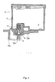
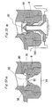
- Fig. 1 shows a cross sectional view of the ink cartridge according to the present invention with a part of the printing apparatus comprising the print head;
- Fig. 2 is an enlarged cross sectional view of the ink supply port of the ink cartridge shown in Fig. 1;
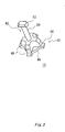
- Fig. 3 shows the valve member of the ink cartridge shown in Fig. 2;
- Fig. 4(A) shows the ink supply port of the ink cartridge with the ink supply needle of the printing apparatus;
- Fig. 4(B) shows the ink supply port of the ink cartridge with the ink supply needle of the printing apparatus inserted therein;
- Fig. 5(A) shows another embodiment of the ink supply port of the ink cartridge;
- Fig. 5(B) shows the ink supply port of the ink cartridge shown in Fig. 5(A) with the ink supply needle of the printing apparatus inserted therein;
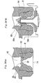
- Fig. 6 (A) shows another embodiment of the ink supply port of the ink cartridge;
- Fig. 6(B) shows the ink supply port of the ink cartridge shown in Fig. 6(A) with the ink supply needle of the printing apparatus inserted therein;
- Fig. 7(A) shows another embodiment of the ink supply port of the ink cartridge;
- Fig. 7(B) shows the ink supply port of the ink cartridge shown in Fig. 7(A) with the ink supply needle of the printing apparatus inserted therein;
- Fig. 8 shows a cross sectional view of another embodiment of the valve member;
- Fig. 9(A) shows another embodiment of the valve member;
- Fig. 9(B) shows a cross sectional view of another embodiment of the valve member;
- Fig. 9(C) shows a cross sectional view of another embodiment of the valve member;
- Fig. 10 shows a cross sectional view of another embodiment of the valve member;
- Fig. 11 shows a cross sectional view of another embodiment of the valve member;
- Fig. 12 shows an embodiment of the ink introducing chamber;
- Fig. 13 (A) is a cross sectional view of an embodiment of the packing retainer for the packing member;
- Fig. 13(B) shows the packing retainer for the packing member shown in Fig. 13(A);
- Fig. 14 shows another embodiment of the packing retainer for the packing member;
- Fig. 15 (A) is a cross sectional view of another embodiment of the packing retainer for the packing member;
- Fig. 15(B) shows the packing retainer for the packing member shown in Fig. 15(A);
- Fig. 16(A) is a cross sectional view of another embodiment of the packing retainer for the packing member;
- Fig. 16(B) shows the packing retainer for the packing member shown in Fig. 16(A);
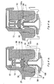
- Fig. 17 (A) is a cross sectional view of another embodiment of the ink cartridge according to the present invention;
- Fig. 17(B) shows the ink cartridge shown in Fig. 17(A) with the ink supply needle of the printing apparatus;
- Fig. 17 (C) shows the ink cartridge shown in Fig. 17(A) with the ink supply needle of the printing apparatus inserted therein;
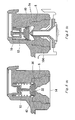
- Fig. 18(A) is a cross sectional view of another embodiment of the ink cartridge according to the present invention;
- Fig. 18(B) shows the ink cartridge shown in Fig. 18(A) with the ink supply needle of the printing apparatus;
- Fig. 18(C) shows the ink cartridge shown in Fig. 18 (A) with the ink supply needle of the printing apparatus inserted therein;
- Fig. 19(A) is a cross sectional view of the valve member shown in Fig. 18(A) to 18(C);
- Fig. 19(B) is a cross sectional view of another embodiment of the valve member;
- Fig. 19(C) is a cross sectional view of another embodiment of the valve member;
- Fig. 20 shows the ink cartridge comprising an extension spring;
- Fig. 21(A) is a cross sectional view of another embodiment of the valve device comprising three elastic support portions;
- Fig. 21(B) is a cross sectional view of the valve device shown in Fig. 21(A) with the ink supply needle of the printing apparatus;
- Fig. 21(C) shows the valve device shown in Fig. 21(A);
- Fig. 21(D) shows the valve device shown in Fig. 21(A) with the ink supply needle of the printing apparatus;
- Fig. 22 (A) is a cross sectional view of another embodiment of the valve device comprising a elastic support-portion;
- Fig. 22(B) is a cross sectional view of the valve device shown in Fig. 22(A) with the ink supply needle of the printing apparatus;
- Fig. 22(C) shows the valve device shown in Fig. 21(A);
- Fig. 22(D) shows the valve device shown in Fig. 21(A) with the ink supply needle of the printing apparatus;
- Fig. 23(A) shows another embodiment of the valve device;
- Fig. 23 (B) shows the valve device shown in Fig. 23(A) with the ink supply needle of the printing apparatus;
- Fig. 24(A) shows another embodiment of the valve device;
- Fig. 24(B) shows the valve device shown in Fig. 24 (A) with the ink supply needle of the printing apparatus;
- Fig. 25 (A) is a cross sectional view of another embodiment of the valve member;
- Fig. 25(B) shows the valve member shown in Fig. 25(A) with the ink supply needle of the printing apparatus;
- Fig. 25 (C) is a cross sectional view of another embodiment of the valve member;
- Fig. 25 (D) shows the valve member shown in Fig. 25(C) with the ink supply needle of the printing apparatus;
- Fig. 26 shows another embodiment of the ink cartridge according to the present invention;
- Fig. 27 shows a cross sectional view of the conventional ink cartridge with a part of the printing apparatus comprising the print head; and
- Fig. 28 is a cross sectional view of another embodiment of the conventional ink cartridge.
- Preferred embodiments of the present invention will now be described in detail with reference to accompanying drawings. The embodiments described as follows do not intend to limit the scope of the present invention, but merely exemplify the invention. All of the features and the combinations thereof described in the embodiment are not necessarily essential to the invention.
- Fig. 1 shows a first embodiment of an ink cartridge according to the present invention. As shown in Fig. 1, an
ink cartridge 2 has an ink chamber 4 for containing ink, and anink supply port 6 designed to establish an ink communication with the ink chamber 4. Theink cartridge 2 is also provided with a packingmember 8 disposed within theink supply port 6, and avalve member 10 located between the ink chamber 4 and the packingmember 8. Thevalve member 10 is always urged toward the packingmember 8 by an elastic force of acompression spring 12. The packingmember 8 is made of an elastic material such as a rubber or a plastic. The ink chamber 4 accommodates therein aporous member 5 which absorbs ink. Because of the fact that ink is absorbed in theporous member 5, ink is retained in the ink chamber in stable without splashing, even when the ink cartridge mounted on a carriage of a printing apparatus moves in reciprocate at a high speed. As theporous member 5 is accommodated in the ink chamber 4, the ink chamber 4 is always depressurized. - Fig. 1 shows a part of the printing apparatus. The printing apparatus has a
print head 102 fixed on the carriage, not shown in the drawings, a taperedink supply needle 104 designed to establish a fluid communication with theprint head 102, and anink cartridge holder 106. Theink cartridge 2 is mounted on theink cartridge holder 106 of the printing apparatus in such a way that theink supply port 6 faces theink supply needle 104 of the printing apparatus. When theink cartridge 2 is mounted on the printing apparatus, the packingmember 8 in theink supply port 6 fits with theink supply needle 104. The ink is then introduced from the ink chamber 4 to theprint head 102 through holes formed in the tip end of theink supply needle 104. - Fig. 2 is an enlarged cross sectional view showing the
ink cartridge 2. Theink supply port 6 is provided with anexternal opening 14 coupling to theink supply needle 104 of the printing apparatus, and aninternal opening 16 opening to the ink chamber 4. - The packing
member 8 is press-fitted in theink supply port 6. The packingmember 8 has a protrudingportion 20 on its outside surface, fitting with a concave 22 formed on the side wall of theink supply port 6, in order to have the packingmember 8 retained in theink supply port 6. The protrudingportion 20 of the packingmember 8 seals with the concave 22 of theink supply port 6. Thus, ink does not leak from theink supply port 6. - The packing
member 8 is made of an elastic material such as a rubber material including a silicon rubber, a chloroprene rubber, a butyl rubber, a ethylene-propylene rubber, a nitrile rubber, and an elastmer material. The packingmember 8 is provided, if desired, with a lubricant coat at areas with which theink supply needle 104 contacts, in order to smoothly receive theink supply needle 104. The lubricant coat consists of a silicon resin or a fluorocarbon resin. - One surface of the packing
member 8 faces the ink chamber 4. This surface of the packing member is formed with acylindrical recess 30 having a diameter compatible to receipt of a part of the valve device, which will be explained in detail hereinbelow. The packingmember 8 has ahole 32 defined in the center thereof, capable of receiving theink supply needle 104 formed in thecylindrical recess 30, having a diameter smaller than the diameter of thecylindrical recess 30, thereby to form an ink channel. - The
hole 32 of the packingmember 8 expands and seals theink supply needle 104 of the printing apparatus, when theink supply needle 104 is inserted into thehole 32. The packingmember 8 is formed with a protrudingrim 34 surrounding thehole 32 formed in the above-mentioned surface of the packingmember 8. - The packing
member 8 has a second surface facing theexternal opening 14, with a first taperedportion 24 and a second taperedportion 26. Each tapered portion on the second surface is tapered from theexternal opening 14 toward the ink chamber 4 for the purpose of guiding theink supply needle 104 of the printing apparatus. The packingmember 8 is also provided with afitting portion 28 formed on the second surface, to fit with theink supply needle 104 of the printing apparatus. - The packing
member 8 is press-fitted in theink supply port 6 and defines anink introducing chamber 36 within theink supply port 6. Theink introducing chamber 36 is an area defined between the packingmember 8 and the ink chamber 4. The valve member 4 is received in theink introducing chamber 36. Theink introducing chamber 36 has acylindrical guide unit 38 having a through bore 38a. Theguide unit 38 receives a part of thevalve member 10 in order to guide thevalve member 10. Theguide unit 38 contacts with the part of thevalve member 10 necessary to have thevalve member 10 moved vertically with respect to the packingmember 8. Thevalve member 10 is always urged by acompression spring 12 toward the packingmember 8, to contact with the packing member for selectively closing the ink channel of the packingmember 8. - Fig. 3 shows an embodiment of the
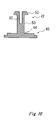
valve member 10. Thevalve member 10 has avalve body 40 contacting with the packingmember 8, and aguide body 42 for guiding thevalve body 40. Theguide body 42 helps thevalve body 40 to move vertically with respect to the packing member, when thevalve member 10 is received in theink introducing chamber 38. Thevalve body 40 has a sealingportion 44 for sealing the ink channel of the packingmember 8 when thevalve body 40 contacts with the packingmember 8, aspring support structure 46 for supporting thecompression spring 12, and anink channel 48 suitable for the passage of ink when the valve body comes out of contact with the packing member by the ink supply needle of the printing apparatus. Here, the sealingportion 44 is substantially flat. A part of theink channel 48 is formed by cutting off the sealingportion 44. Theguide body 42 has anaxial portion 50 connecting to thevalve body 40, and aguide block 52 formed at an end of theaxial portion 50 opposite to thevalve body 40. - Referring back to Fig. 2, the
guide block 52 is slidably received in theguide unit 38. Theguide block 52 has a diameter larger than a diameter of the through bore 38a of theguide unit 38. Theguide block 52 of thevalve member 10 cooperates with theguide unit 38, to have thevalve body 10 move vertically with respect to the packingmember 8. - The
print head 102 is of an ink jet type print head normally referred to as a piezoelectric type print head. In the piezoelectric type print head, by driving a piezoelectric transducer a pressure chamber is expanded to lead ink in, and applies a pressure to ink to eject ink droplets out of the print head. It is necessary to dissolve, during manufacturing, any bubbles in the ink within the cartridge of this type of print head, because bubbles in the ink may cause inadequate compression of the pressure chamber so that ink droplets do not eject as they are designed. - In this case, the ink is injected in the ink cartridge at a negative pressure of minus 1 atom of the atmospheric pressure (1.033kg / per square meter) when the ink cartridge is manufactured. The compression coil spring is designed to be strong enough to urge the
valve member 10 toward the packingmember 8 in order to have thevalve member 10 form a contact with the packingmember 8, even under the low pressure condition. - The
internal opening 16 formed at the side of theink supply port 6 opening to the ink chamber 4 has a dimension larger than the dimension of theink introducing chamber 36 in which thevalve member 10 is accommodated. The result is, ink can smoothly be introduced to theink introducing chamber 36, and flown to theink supply port 6. Afilter 54 is provided between theinternal opening 16 of theink supply port 6 and the ink chamber 4 of the ink cartridge. Thefilter 54 collects dust or foreign particles existing in the ink chamber 4. Furthermore, as thefilter 54 has a dimension same as that of theinternal opening 16, ink passes smoothly through thefilter 54. - A sealing
film 56 which is designed to be penetrated by the ink supply needle may be adhered to cover theexternal opening 14 for sealing theink supply port 6 prior to use. -Thesealing film 56 serves to close theink supply port 6 and also to retain the packingmember 8 at theexternal opening 14 of theink supply port 6. - The operation of the packing
member 8 and thevalve member 10, when theink cartridge 2 is mounted on the printing apparatus will be explained in the following in the present embodiment. - As shown in Fig. 2, when the ink cartridge is not mounted on the printing apparatus, the
valve body 40 is urged toward the packingmember 8 by thecompression spring 12. The sealingportion 44 contacts with the protrudingrim 34 surrounding thehole 32 of the packingmember 8. Thus, theink introducing chamber 36 is closed by the packingmember 8 and thevalve member 10. - As shown in Fig. 4(A), the
external opening 14 of theink supply port 6 is adjusted to fit theink supply needle 104 to have theink cartridge 2 depressed in theink cartridge holder 106 of the printing apparatus. The taperedink supply needle 104 then penetrates the sealingfilm 56, to be inserted into thefitting portion 28 whilst being guided by the first and secondtapered portions member 8. When theink cartridge 2 is further pushed into thecartridge holder 106 of the printing apparatus, the taperedink supply needle 104 is smoothly inserted into thehole 32 of the packingmember 8. This causes thehole 32 to expand, and thefitting portion 28 of the packingmember 8 seals theink supply needle 104. Theink supply needle 104 urges theflat sealing portion 44 of thevalve member 10. At the same time, thevalve member 10 moves toward the ink chamber 4 against the elastic force of thecompression spring 12. - The
ink supply needle 104 becomes held in communication with theink introducing chamber 36 via the hole formed in the tip end of theink supply needle 104, and thus allows ink to flow to theprint head 102. - When the
cartridge 2 is removed from the printing apparatus, theink supply needle 104 is detached from the packingmember 8. The result is, thevalve member 10 is urged toward the packingmember 8 by the elastic force of thecompression spring 12. The sealingportion 44 of thevalve member 10 closes the ink channel of the packingmember 8 when theink supply needle 104 is completely detached from the packingmember 8. It means that when theink supply needle 104 is released from thefitting portion 28 of the packingmember 8, at the same time, the sealingportion 44 of thevalve body 40 is urged toward the packingmember 8 to close theink introducing chamber 36. - As shown in Figs. 5(A) and 5(B), the packing
member 8 may not be formed with a protrudingrim 34 surrounding thehole 32 of the packingmember 8, to have thevalve body 40 contact with the surface of thecylindrical recess 30. Fig. 5(B) shows the packingmember 8 and theink supply needle 104 of the printing apparatus, when theexternal opening 14 of theink cartridge 2 is designed to have a size allowing theink supply needle 104 of theink cartridge 2 to be pushed into theink cartridge holder 106. In this case, the same operation as explained with reference to Figs. 4(A) and 4(B) can be obtained. - Furthermore, even when dust or foreign particles is contained in ink, the sealed connection between the packing
member 8 and thevalve member 10 can be ensured, because the contacting surface between thevalve body 40 and thecylindrical recess 30 of the packingmember 8 is large. - As shown in Figs. 6(A) and 6(B), the packing
member 8 may have a taperedportion 58 larger than the taperedink supply needle 104 at the second surface. Furthermore, as shown in Figs. 7(A) and 7(B), the packingmember 8 may have a single taperedportion 60 tapered from theexternal opening 14 to thehole 32 of the packingmember 8. In these cases, when theink cartridge 2 is pushed into theink cartridge holder 106 to have theink supply needle 104 inserted into thehole 32 of the packingmember 8, the taperedportion 58 and the taperedportion 60 each fit with theink supply needle 104. The same operation as explained with reference to Figs. 4(A) and 4(B) can also be obtained in these cases. - Furthermore, even when dust is contained in ink, the sealed connection between the packing
member 8 and thevalve member 10 can be ensured, because the contacting surface between thevalve body 40 and thecylindrical recess 30 of the packingmember 8 is large. - Further, in the embodiment shown in Figs. 7(A) and 7(B), the sealed connection between the packing
member 8 and thevalve member 10 can be ensured because the fitting force -between the taperedportion 60 and theink supply needle 104 is strong. - Although the packing
member 8 shown in this embodiment is formed as one unit, the packingmember 8 may be separately formed as comprising two units; one of which is a part with which thevalve member 10 contacts and the other of which is a part with which theink supply needle 104 fits. - Fig. 8 shows another example of the
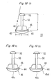
valve member 10 having a surface at the sealingportion 44, facing the packingmember 8, formed with aspherical surface 45 to contact with the tip end of theink supply needle 104. With thisspherical surface 45 of thevalve member 10, the sealed connection between the packingmember 8 and thevalve member 10 is ensured, even when the position of thevalve member 10 varies. - Fig. 9(A) shows another embodiment of the
valve member 10. The components of thevalve member 10 shown in Fig. 9(A) are formed separately from one another, including avalve body 40 to form a contact with the packingmember 8, and aguide body 42 for guiding thevalve body 40 vertically with respect to the packingmember 8. Thevalve body 40 has a sealingportion 44 and a plurality of, at least three,spring support structure 46 around the sealingportion 44. Theguide body 42 is formed as one piece, with anaxial portion 50 being connected to thevalve body 40 and aguide block 52. Theguide block 52 guides thevalve body 40 vertically with respect to the packingmember 8, in cooperation with theguide unit 38 of theink introducing chamber 36. The end of theaxial portion 50 of theguide body 42, opposite to theguide block 52, is secured to the sealingportion 44 of thevalve body 40, to assemble thevalve member 10. - The
valve member 10 is incorporated in theink supply port 6 by inserting theguide body 42 from theinternal opening 16, to be passed through theguide unit 38 of theink introducing chamber 36, entering thecompression spring 12 from theinternal opening 16 to be placed around theink introducing chamber 36, and fixing thevalve body 40 to theguide body 42. - The
valve body 40 and theguide body 42 may be fixed to each other by providing a fixinghole 40a to thevalve body 40. Theguide body 42 is inserted into the fixinghole 40a of thevalve body 40, and fixed by heat welding or adhesive as shown in Fig. 9(B). Otherwise, thevalve body 40 and theguide body 42 may be fixed to each other by forming a fixing hole having a thread to thevalve body 40, forming a thread to theaxial portion 50, and connecting these parts to each other as shown in Fig. 9(C). - Fig. 10 shows another embodiment of the
valve member 10. Thevalve member 10 has avalve body 40 and aguide body 42. Theguide body 42 is provided with anaxial portion 50 and aguide block 52. Theaxial portion 50 and theguide block 52 of theguide body 42 are formed as one unit. Theguide body 42 is made of an elastic material such as a plastic and formed with agroove 62 extending from theguide block 52 through theaxial portion 50. Thevalve body 40 maybe made of the same elastic material, such as a plastic, and formed as one unit with theguide body 42. When theink cartridge 2 is mounted on the printing apparatus, theink supply needle 104 contacts with and urges thevalve body 40. Thevalve body 40 may therefore be made of a soft and flexible material which does not damage the tip end of theink supply needle 104. Theguide block 52 of theguide body 42 may be tapered toward thevalve body 40 as shown in Fig. 10. - In this embodiment, the
valve member 10 is incorporated in theink supply port 6 by entering thecompression spring 12 from theinternal opening 16 to be placed around theink introducing chamber 36. The edge of theguide body 42 having thegroove 62 is pushed into the through bore 38a of theguide unit 38. Theguide block 52 has agroove 62 which allows theguide block 52 to be buckled as it passes through the throughbore 38, and then spreads to be retained in theguide unit 38. In this case, thevalve member 10 can be formed as one unit, therefore, the number of parts and working process are reduced. - In the embodiment as described above, the
guide block 52 of thevalve member 10 has agroove 62. However, theguide unit 38 may be formed to allow splitting into a plurality of strips for elastically accepting theguide block 52 of the valve device. - As the
valve member 10 is contained in theink introducing chamber 36, thevalve member 10 needs to be manufactured in a small size. This leads that ink is not provided smoothly to the print head even when the ink channel is open. Therefore, as shown in Fig. 11, thevalve member 10 is formed with adepression 44a and the penetratingportion 44b formed at the sealingportion 44 of thevalve body 40 to allow ink to smoothly pass therethrough. The penetratingportion 44b is formed at the outside of the sealing portion so that the sealingportion 44 can close thehole 32 of the packingmember 8 when the sealingportion 44 contacts with the packingmember 8. Thevalve member 10 preferably has a plurality of thesedepressions 44a and penetratingportions 44b in order to pass ink from the ink chamber 4 to the print head smoothly. - The
ink introducing chamber 36 may have adepression 36a formed at the side wall of theink introducing chamber 36. Thedepression 36a is formed from the upper point where the sealingportion 44 of thevalve body 40 positions when thevalve member 10 is not urged by theink supply needle 104 to the point where the sealingportion 44 of thevalve body 40 positions when thevalve member 10 is urged by theink supply needle 104 in Fig. 12. In this embodiment, ink is provided smoothly to the print head through thedepression 36a. Thevalve member 10 having adepression 44a as shown in Fig. 11 may be used with thisink introducing chamber 36 as shown in Fig. 12. - As for the
ink cartridge 2 according to the present invention, the ink of theink supply port 6 is sealed by the connection between the packingmember 8 and thevalve member 10. Thus it is not necessary to close theexternal opening 14 with a sealing film or any equivalent member thereof. Therefore, as shown in Figs. 13(A) and 13(B), the sealingfilm 56 provided at theexternal opening 14 may be formed with ahole 56a which enables theink supply needle 104 to pass through. The hole may-be formed by cutting the film in a cross shape as shown in Fig. 14-. By making the hole, the ink supply needle smoothly pass through the film. - Furthermore, as shown in Figs 15(A) and 15(B), the
ink cartridge 2 may have a protrudingportion 14a protruding from theexternal opening 14 toward the center thereof, as a retainer for retaining the packingmember 8 at theexternal opening 14 of theink supply port 6. The protruding portion can be simply formed by protruding a part of theexternal opening 14. The result is, the number of parts or components and manufacturing process are reduced. - The
external opening 14 may have a retreatingopening 14b as shown in Fig. 16(A) and 16(B). The sealingfilm 56 is attached at theexternal opening 14 to retain the packingmember 8 at theexternal opening 14. - In this embodiment, the
ink supply port 6 is open to the external ambient air, therefore, the packingmember 8 and thevalve member 10 are not influenced by the expansion and the contraction of the air in theink supply port 6. - Fig. 17 (A) 17 (B) and 17 (C) show another embodiment of the ink cartridge according to the present invention. A packing
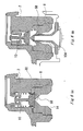
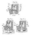
member 8 and avalve member 10 are provided in theink supply port 6 in the same way as the embodiment shown in Fig. 2. Theink supply port 6 has anexternal opening 14 designed to face theink supply needle 104 of the printing apparatus, and aninternal opening 16 designed to open to the ink chamber 4. The parts and components having the same symbols as Fig. 2 and not specifically mentioned here have the same operations and effects as those shown in Fig. 2. - The packing
member 8 has a first surface facing the ink chamber 4 with a protrudingportion 8a protruding from thefitting portion 28 toward the ink chamber 4. The first surface has ahole 18a, whose diameter is smaller than the diameter of the needle of the recording apparatus. - The packing
member 8 has a second surface facing theexternal opening 14 with a first taperedportion 24 and a second taperedportion 26 each tapered from theexternal opening 14 toward the ink chamber 4 at the second surface. The function of this is to guide theink supply needle 104 of the printing apparatus. The packingmember 8 further has afitting portion 28 to fit with theink supply needle 104 of the printing apparatus. - The
valve member 10 has avalve body 40 and aguide body 42. Thevalve body 40 has a sealingportion 44 and aspring support structure 46. Theguide body 42 has anaxial portion 50 and aguide block 52. The sealingportion 44 of thevalve body 40 has a surface facing the packingmember 8 formed with a protrudingportion 45b to contact with the tip end of theink supply needle 104. The protrudingportion 45b has a size compatible with thehole 18a of the protrudingportion 8a of the packingmember 8. Thevalve member 10 is received in theguide unit 38 of theink introducing chamber 38, to be moved vertically with respect to the packingmember 8. - The protruding
portion 45b has a height that permits it to form a contact with the tip end of theink supply needle 104 at the time when theink supply needle 104 forms a sealed connection with the packingmember 8 as shown in Fig. 17(B). It means that thevalve member 10 is urged by theink supply needle 104 to open theink supply port 6 at the time when theink supply needle 104 and the packingmember 8 form a sealed connection with each other. Thus, undesirable air or bubble do not enter theink supply port 6. - In this embodiment, the tip end of the
ink supply needle 104 contacts the protrudingportion 45b of the sealingportion 44 at the time when the taperedink supply needle 104 fits with the packingmember 8. This forms a sealed connection between them, by mounting theink cartridge 2 on the printing apparatus. - when the
ink cartridge 2 is further pushed toward the printing apparatus, theink supply needle 104 fits into thefitting portion 34 of the packing member and is inserted into thehole 18a of the protrudingportion 8a of the packingmember 8 whilst forcing out any air. Then, the ink can be provided to theprint head 102. Thevalve member 10 is forcibly separated from the packingmember 8 when theink supply needle 104 is inserted into theink supply port 6 whilst forming a sealed connection with the packingmember 8 as described above. Therefore, the air compressed by the ink supply needle when it is inserting in the ink supply port does not enter theink supply port 6 and theink supply needle 104. - When, on the other hand, the
cartridge 2 is removed from the printing apparatus, theink supply needle 104 is detached from the packingmember 8. Thevalve member 10 is urged toward the packingmember 8 by the elastic force of thecompression spring 12. The protrudingportion 45b of the sealingportion 44 of thevalve member 10 is accepted into thehole 18a of the packingmember 8, whilst theink supply needle 104 be detached from the packingmember 8. The sealingportion 44 of thevalve member 10 forms a contact with the protrudingportion 8a of the packingmember 8. This closes theink introducing chamber 36 when theink supply needle 104 is almost detached from the packingmember 8 but is still forming the sealed connection with thefitting portion 28 of the packingmember 8. Thus, the ink does not leak from, and undesirable air or bubble does not enter the ink cartridge through theexternal opening 14 of the ink supply port. - Fig. 18(A) 18 (B) and 18(C) show another embodiment of the ink cartridge according to the present invention. The ink cartridge has a packing
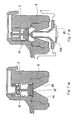
member 8. The packingmember 8 has a protrudingportion 8a and ahole 18a formed at the protrudingportion 8a of the packingmember 8 in the same way as that shown in Figs. Fig. 17(A) 17(B) and 17(C). - The
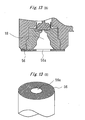
valve member 10 has avalve body 40 and aguide body 42. Thevalve body 40 has a sealingportion 44 and aspring support structure 46. Theguide body 42 has anaxial portion 50 and aguide block 52. The sealingportion 44 of thevalve body 40 has a surface facing the packingmember 8, formed with aconvex surface 45. Theconvex surface 45 is a spherical surface. The spherical surface of thevalve body 40 has a diameter of curvature larger than a diameter of a widest part of thevalve body 40. - Fig. 19(A) shows an enlarged cross sectional view of the
valve member 10 having a sphericalconvex surface 45. Theconvex surface 45 of the sealingportion 44 of thevalve body 40 is like a part of a sphere having a diameter "R". The diameter R of the sphere is larger than the length "L" of theaxial portion 50 of thevalve member 10. Thus, the sealed connection between the packingmember 8 and thevalve member 10 is ensured even when the position of thevalve member 10 varies. - Assuming the diameter of curvature of the spherical
convex surface 45 of thevalve body 40 as "R", "2R" (2 x R) is at least longer than the widest part "d" of thevalve body 40 as shown in Fig. 19 (A) . - In this embodiment, the tip end of the
ink supply needle 104 contacts the spherical convex 45 of the sealingportion 44. This occurs at the time when the taperedink supply needle 104 fits with the packingmember 8, to form the sealed connection with each other when mounting theink cartridge 2 on the printing apparatus. - When the
ink cartridge 2 is further pushed toward the printing apparatus, theink supply needle 104 is guided by the taperedportion 58 to contact with the center of theconvex surface 45 of thevalve member 10. Under this condition, theink supply needle 104 is inserted into thehole 18a of the protrudingportion 8a of the packingmember 8. - The
valve member 10 is forced to come out of contact with the packingmember 8 when theink supply needle 104 is inserted into theink supply port 6 whilst forming the sealed connection with the packingmember 8 as described above. Therefore, the air compressed by the ink supply needle does not enter theink supply port 6. - Further in this embodiment, the
ink supply needle 104 contacts with the center of the sphericalconvex surface 45 having a large diameter of curvature, and thevalve member 10 is regulated by itsaxial portion 50, therefore, contact between thevalve member 10 and theink supply needle 104 is ensured. - When, on the other hand, the
cartridge 2 is removed from the printing apparatus, theink supply needle 104 is detached from the packingmember 8. Thevalve member 10 is urged toward the packingmember 8 by the elastic force of thecompression spring 12. Theconvex surface 45 of the sealingportion 44 of thevalve member 10 forms a contact with the protrudingportion 8a of the packingmember 8, to close theink introducing chamber 36. This occurs when theink supply needle 104 is almost detached from the packingmember 8 but is still forming a sealed connection with thefitting portion 28 of the packingmember 8. Thus, the ink does not leak from, and undesirable air bubbles do not enter theexternal opening 14. Furthermore, as the sealingportion 44 has the sphericalconvex surface 45, the sealed connection between the packingmember 8 and thevalve member 10 is ensured even when the position of thevalve member 10 varies. - The spherical
convex surface 45 of thevalve member 10 may have aflat surface 45c having a diameter smaller than the diameter of thehole 18a of the protrudingportion 8a of the packingmember 8 as shown in Fig. 19(B). In this case, the contacting surface between theink supply needle 104 and thevalve member 10 is large, to enforce the contact therebetween without reducing the sealed connection between theink supply needle 104 and the packingmember 8. - Furthermore, the closing
surface 44 of thevalve member 10 may be formed as aconical shape 45d having its point removed, to leave aflat surface 45c remained. In this case, the contact between theink supply needle 104 and thevalve member 10 is enforced as well, without reducing the sealed connection between theink supply needle 104 and the packingmember 8. - The elastic member may be an
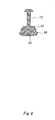
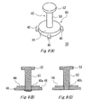
extension spring 64 as shown in Fig. 20. Theextension spring 64 is fixed to theink cartridge 2 at an end by the packingmember 8 to have the other end of theextension spring 64 contact with thevalve member 10. Thevalve member 10 is forced toward the packingmember 10. In this case, the valve member does not need to have aspring support structure 46, and theink cartridge 2 does not need to have aguide unit 38 in theink introducing chamber 36. The result is, that the structure of theink cartridge 2 can be simplified, thus, the manufacturing process can be reduced. - Figs. 21 and 22 shows another example of the valve device according to the present invention. The
valve device 70 has avalve body 72 to form contact with the packingmember 8, and anelastic support portion 74 for supporting thevalve body 72 in order to have thevalve body 72 contact with the packingmember 8. Theelastic support portion 74 is made of an elastic material such as a hard rubber, a plastic material having a high elastic modulus, or an elastomer material. Theelastic support portion 74 is capable of bending when theink supply needle 104 fits with the packing member, to urge thevalve body 72 of thevalve device 70. Thevalve body 72 and theelastic support portion 74 may be separately formed, or may be formed as one unit. Theelastic support portion 74 of thevalve device 70 urges thevalve body 72 toward the packingmember 8. At the same time, thevalve body 72 contacts with the packingmember 8, and guides the valve member vertically with respect to the packingmember 8. Therefore, the number of parts can be reduced. - The
valve device 70 may have a plurality ofelastic support portions 74, for example, three in Fig. 21, or only oneelastic support portion 74 as shown in Fig. 22. - Fig. 23(A) and 23(B) show another embodiment of the valve device according to the present invention. The
valve device 80 has avalve member 82 to form a contact with the packingmember 8 and anelastic member 84 for urging thevalve member 82 toward the packingmember 8 in order to have thevalve member 82 contact with the packingmember 8. Theelastic member 84 is made of a polymeric elastomer or a rubber capable of expanding. - The
valve body 82 is urged to selectively contact with the packingmember 8 by theelastic member 84 connected to thecylindrical recess 30 of the packingmember 8 in the embodiment shown in Fig. 23 (A) . Thevalve body 82 is urged by theink supply needle 104 of the printing apparatus toward the ink chamber, to open thevalve device 80. Thus, the ink is provided from the ink chamber to theprint head 102 of the printing apparatus through the hole of theink supply needle 104. - A part of the
valve body 82 is fixed at the packingmember 8 as shown in Figs. 24 (A) and 24(B). Thevalve body 82 is urged to contact with the packingmember 8 by theelastic member 84 in this case as well. Thevalve body 84 is urged toward the ink chamber by theink supply needle 104, to open the hole of the packingmember 8. The ink is then provided from the ink chamber to theprint head 102 of the printing apparatus through the hole of theink supply needle 104. - The
valve device 80 maybe formed as one unit with the packingmember 8. It means that thevalve device 80 is fixed to the packingmember 8 as its part. Thus, the number of parts and manufacturing process can be reduced. - The
valve body 40 of thevalve member 10 may have a surface facing the packing member provided with a notch as shown in Figs. 25(A) to 25(D). The notch 40c of thevalve body 40 shown in Figs. 25(A) and 25(B) has an angle the same as that of the taperedink supply needle 104. The notch 40d of thevalve body 40 shown in Figs. 25(C) and 25(D) has an angle smaller than that of the taperedink supply needle 104. These reduce the damage to theink supply needle 104 when theink supply needle 104 urges thevalve member 10. In particular, when theink supply needle 104 contacts thevalve body 40 as shown in Figs. 25(C) and 25(D), the tip end of theink supply needle 104 does not contact with thevalve body 40 of thevalve member 10, therefore the tip end of theink supply needle 104 is not damaged. - The packing
member 8 may have two fitting portions, a firstfitting position 28a for fitting the ink supply needle of the printing apparatus when theink supply needle 104 is inserted from theexternal opening 14, and a secondfitting position 28b for fitting theink supply needle 104 when theink supply needle 104 is further inserted toward the ink chamber 4. In this case, each of thefitting portions ink supply needle 104. Thus, the sealed connection between the packing member and theink supply needle 104 can be enforced. Each of thefitting portions fitting portion 28a closer to theexternal opening 14 is not formed with a hole and is sealed initially prior to use. In such a case, the number of parts can be reduced because the ink cartridge does not have a sealing film to seal thesupply port 6 prior to use. Even in this case, thefitting portion 28a is formed as tapered as shown in Fig. 26, so theink supply needle 104 can smoothly penetrate the sealedfitting portion 28a. - The ink cartridge according to the present invention may be used as an off-carriage type ink cartridge which is mounted on a fixed part of the body of the printer and connected to the print head which is mounted on the carriage, through a flexible ink supply tube.
- The ink cartridge according to the present invention may also be applied to a printing apparatus in which a heating element is used as a pressurizing means not only to the printing apparatus in which the piezoelectric transducer is used as a pressurizing means of the print head.
- As described above, according to the present invention, an ink cartridge and an ink supply system are capable of closing the ink supply channel when it is not mounted on the printing apparatus and capable of opening the ink supply channel to provide ink to the print head when it is mounted on the printing apparatus. A printing apparatus employing the ink cartridge or the ink supply system is also provided by the present invention.
- Furthermore, Ink can be supplied from the ink supply port to the ink supply needle without having air or bubble enter the ink supply port because the valve device is urged by the ink supply needle of the printing apparatus to open the ink channel under a state where the ink supply needle is sealed by the packing member.
- Furthermore, the ink supply port can be sealed without having air or bubble enter the ink supply port because the valve device comes to close the ink channel of the packing member before the ink supply needle of the printing apparatus is completely detached from the packing member.
- Furthermore, the ink supply needle can be smoothly inserted in the packing member because the packing member is made of an elastic material and provided with a lubricant coat at least at an area with which the ink supply needle contacts.
- Furthermore, the packing member can seal the ink supply needle because the packing member includes a tapered portion or a fitting portion fitting the ink supply needle.
- Furthermore, the ink supply needle can securely contact with the valve device, because the valve device includes a substantially flat surface with which the ink supply needle contacts.
- Furthermore, the valve body can be moved substantially vertically with respect to the packing member because the valve device includes a guide body for guiding the valve body to slide substantially vertically with respect to the packing member.
- Furthermore, manufacturing process can be simplified and reduced because the number of parts or components necessary for assembling the ink cartridge according to the present invention is reduced.
- Further embodiments are listed below:
- 1. An ink cartridge (2) for a printing apparatus providing ink to a print head (102) through a tapered ink supply needle (104) and removably attached to the print head (102), comprising:
- an ink chamber (4) for containing ink;
- an ink supply port (6) for supplying ink from said ink chamber (4) to the print head (102) of the printing apparatus, said ink supply port (6) comprising an external opening (14);
- a packing member (8) provided in said ink supply port (6), forming an ink channel for allowing a flow of ink, said packing member (8) sealing the ink supply needle (104) of the printing apparatus by fitting therewith; and
- a valve device (10, 12, 64, 70 and 80) contained in said ink supply port (6) elastically abutting against said packing member (8), said valve device (10, 12, 64, 70 and 80) selectively opening and closing said ink channel in conjunction with the ink supply needle (104).
- 2. An ink cartridge (2) for a printing apparatus providing ink to a print head (102) through an ink supply needle (104) and removably attached to the print head (102), comprising:
- an ink chamber (4) for containing ink;
- an ink supply port (6) for supplying ink from said ink chamber (4) to the print head (102) of the printing apparatus, said ink supply port (6) comprising an external opening (14);
- a packing member (8) provided in said ink supply port (6), forming an ink channel for allowing a flow of ink, said packing member (8) sealing the ink supply needle (104) of the printing apparatus by fitting therewith; and
- a valve device (10, 12, 64, 70 and 80) contained in said ink supply port (6) elastically abutting against said packing member (8), said valve device (10, 12, 64, 70 and 80) selectively opening and closing said ink channel in conjunction with the ink supply needle (104), said valve device (10, 12, 64, 70 and 80) being urged by the ink supply needle (104) of the printing apparatus to open said ink channel at a same time when the ink supply needle (104) is sealed by said packing member (8).
- 3. An ink cartridge (2) as set forth in 2, characterized in that said valve device (10, 12, 64, 70 and 80) comes to close said ink channel of said packing member (8) before the ink supply needle (104) of the printing apparatus is completely detached from said packing member (8).
- 4. An ink cartridge (2) for a printing apparatus providing ink to a print head (102) through an ink supply needle (104) and removably attached to the print head (102), comprising:
- an ink chamber (4) for containing ink;
- a porous member (5) accommodated in said ink chamber (4) for absorbing ink;
- an ink supply port (6) for supplying ink from said ink chamber (4) to the print head (102) of the printing apparatus, said ink supply port (6) comprising an external opening (14);
- a packing member (8) provided in said ink supply port (6), forming an ink channel for allowing a flow of ink, said packing member (8) sealing the ink supply needle (104) of the printing apparatus by fitting therewith; and
- a valve device (10, 12, 64, 70 and 80) contained in said ink supply port (6) elastically abutting against said packing member (8), said valve device (10, 12, 64, 70 and 80) selectively opening and closing said ink channel in conjunction with the ink supply needle (104).
- 5. An ink cartridge (2) for a printing apparatus providing ink to a print head (102) through an ink supply needle (104) and removably attached to the print head (102), comprising:
- an ink chamber (4) for containing ink;
- an ink supply port (6) for supplying ink from said ink chamber (4) to the print head (102) of the printing apparatus, said ink supply port (6) comprising an external opening (14);
- a packing member (8) provided in said ink supply port (6), forming an ink channel for allowing a flow of ink, said packing member (8) sealing the ink supply needle (104) of the printing apparatus by fitting therewith, said packing member (8) comprising a hole (32) and a protruding rim (34) surrounding said hole (32); and
- a valve device (10, 12, 64, 70 and 80) contained in said ink supply port (6) elastically abutting against said packing member (8), said valve device (10, 12, 64, 70 and 80) selectively opening and closing said ink channel in conjunction with the ink supply needle (104).
- 6. An ink cartridge (2) as set forth in 5, characterized in that said packing member (8) comprises a first surface facing said ink Chamber (4) formed with a cylindrical recess (30) having a diameter acceptable to receive a part of said valve device (10, 70 and 80) at said first surface.
- 7. An ink cartridge (2) as set forth in 6, characterized in that said hole (32) of said packing member (8) having a diameter smaller than said diameter of said cylindrical recess (30) at said first surface.
- 8. An ink cartridge (2) for a printing apparatus providing ink to a print head (102) through an ink supply needle (104) and removably attached to the print head (102), comprising:
- an ink chamber (4) for containing ink;
- an ink supply port (6) for supplying ink from said ink chamber (4) to the print head (102) of the printing apparatus, said ink supply port (6) comprising an external opening (14);
- a packing member (8) provided in said ink supply port (6), forming an ink channel for allowing a flow of ink, said packing member (8) sealing the ink supply needle (104) of the printing apparatus by fitting therewith; and
- a valve device (10, 70 and 80) contained in said ink supply port (6) elastically abutting against said packing member (8), said valve device (10, 70 and 80) selectively opening and closing said ink channel in conjunction with the ink supply needle (104), said valve device (10, 70 and 80) comprising a valve body (40, 72 and 82) contacting with said packing member (8) and comprising a substantially flat surface with which the ink supply needle (104) contacts.
- 9. An ink cartridge (2) for a printing apparatus providing ink to a print head (102) through an ink supply needle (104) and removably attached to the print head (102), comprising:
- an ink chamber (4) for containing ink;
- an ink supply port (6) for supplying ink from said ink chamber (4) to the print head (102) of the printing apparatus, said ink supply port (6) comprising an external opening (14);
- a packing member (8) provided in said ink supply port (6), forming an ink channel for allowing a flow of ink, said packing member (8) sealing the ink supply needle (104) of the printing apparatus by fitting therewith; and
- a valve device (10) contained in said ink supply port (6) elastically abutting against said packing member (8), said valve device (10) selectively opening and closing said ink channel in conjunction with the ink supply needle (104), said valve device (10) comprising:
- a valve body (40) contacting with said packing member (8) and urged by the ink supply needle (104) of the printing apparatus to open said ink channel when the ink cartridge (2) is mounted on the printing apparatus; and
- a guide body (42) for guiding said valve body (40) to slide substantially vertically with respect to said packing member (8) .
- 10. An ink cartridge (2) as set forth in one of 1, 2, 4 and 5, characterized in that said valve device (10, 12, 64 and 80) comprises:
- a valve member (10 and 82) selectively contacting with a surface of said packing member (8), said valve member (10 and 82) being forced by the ink supply needle (104) of the printing apparatus when the ink cartridge (2) is mounted on the printing apparatus; and
- an elastic member (12, 64 and 84) always urging said valve member (10 and 82) toward said packing member (8).
- 11. An ink cartridge (2) as set forth in 10, characterized in that said valve member (10) comprises a support structure (46) for supporting said elastic member (12 and 64).
- 12. An ink cartridge (2) as set forth in 11, characterized in that said support structure (46) is radially shaped.
- 13. An ink cartridge (2) as set forth in 10, characterized in that said valve member (10) comprises a flange for supporting said elastic member (12 and 64).
- 14. An ink cartridge (2) as set forth in 1, characterized in that said packing member (8) comprises a second surface facing said external opening (14) with a tapered portion (24, 26, 58 and 60) tapered from said external opening (14) toward said ink chamber (4) at said second surface, for guiding the ink supply needle (104) of the printing apparatus.
- 15. An ink cartridge (2) as set forth in 14, characterized in that said tapered portion (24, 26, 58 and 60) fits with the ink supply needle (104).
- 16. An ink cartridge (2) as set forth in 1, characterized in that said packing member (8) comprises a second surface facing said external opening (14) with a fitting portion (28) to fit with the ink supply needle (104) of the printing apparatus.
- 17. An ink cartridge (2) as set forth in 1, characterized in that said packing member (8) is made of an elastic material and provided with a lubricant coat at least at an area with which the ink supply needle (104) contacts.
- 18. An ink cartridge (2) as set forth in 9, characterized in that said valve body (40) comprises:
- a sealing portion (44) for closing said ink channel of said packing member (8) when said valve device (10) contacts with said packing member (8); and
- an ink channel allowing ink to pass therethrough when said valve body (40) is urged to come out of contact with said packing member (8) by the ink supply needle (104) of the printing apparatus.
- 19. An ink cartridge (2) as set forth in 18, characterized in that a part of said ink channel of said valve body (40) is formed by cutting off said sealing portion (44).
- 20. An ink cartridge (2) as set forth in 18, characterized in that said sealing portion (44) of said valve body (40) comprises a substantially flat surface with which the ink supply needle (104) contacts.
- 21. An ink cartridge (2) as set forth in 9, characterized in that said guide body comprises:
- an axial portion (50) being connected to said valve body (40); and
- a guide block (52) formed at an end of said axial portion (50) opposite to said valve body (40), said guide block (52) guiding said valve body (40) to slide substantially vertically with respect to said packing member (8).
- 22. An ink cartridge (2) as set forth in 21, characterized in that said axial portion (50) of said guide body (42) is formed as one unit with said valve body (40).
- 23. An ink cartridge (2) as set forth in 21, further comprising a guide unit (38) provided in said ink supply port (6) to receive said guide block (52) of said guide body (42).
- 24. An ink cartridge (2) as set forth in 9, characterized in that said valve body (40) and said guide body (42) are separately formed and fixed to each other by fixing means.
- 25. An ink cartridge (2) as set forth in 9, characterized in that said valve body (40) and said guide body (42) are formed as one unit with each other.
- 26. An ink cartridge (2) as set forth in 9, characterized in that said guide body (42) is made of an elastic material.
- 27. An ink cartridge (2) as set forth in 21, characterized in that said guide body (42) is made of an elastic material and formed with a groove (62) extending from said guide block (52) through said axial portion (50).
- 28. An ink cartridge (2) as set forth in 9, characterized in that said valve body (40) of said valve device (10) comprises a surface facing said packing member (8) formed with a convex surface.
- 29. An ink cartridge (2) as set forth in 9, characterized in that said valve body (40) of said valve device (10) comprises a surface, facing said packing member (8), formed with a protruding portion (45b) to contact with a tip end of the ink supply needle (104).
- 30. An ink cartridge (2) as set forth in 9, characterized in that said valve body (40) of said valve device (10) comprises a surface, facing said packing member (8), provided with a notch (40c and 40d).
- 31. An ink cartridge (2) as set forth in 30, characterized in that said notch (40c) of said valve body (40) has a tapered angle which is the same as that of the tapered ink supply needle (104) .
- 32. An ink cartridge (2) as set forth in 30, characterized in that said notch (40d) of said valve body (40) has a tapered angle which is smaller than that of the tapered ink supply needle (104) .
- 33. An ink cartridge (2) as set forth in one of 8 and 9, characterized in that said valve body (40) of said valve device (10) comprises a surface formed with a spherical surface (45) contacting with said packing member (8).
- 34. An ink cartridge (2) as set forth in 33, characterized in that said spherical surface (45) of said valve device (10) has a diameter of curvature larger than a diameter of a widest part of said valve body (40).
- 35. An ink cartridge (2) as set forth in 8, characterized in that said packing member (8) comprises a first surface facing said ink chamber (4) with a protruding portion (8a) having a hole (18a) whose diameter is smaller than the diameter of the ink supply needle (104) of the printing apparatus.
- 36. An ink cartridge (2) as set forth in one of 8 and 11, characterized in that said spherical surface (45) of said valve device (10) is formed with a flat portion (45c) with which the ink supply needle (104) contacts.
- 37. An ink cartridge (2) as set forth in 1, 2, 4 and 5, characterized in that said valve device (70) comprises:
- a valve body (72) contacting with said packing member (8) and urged by the ink supply needle (104) of the printing apparatus to open said ink channel when the ink cartridge (2) is mounted on the printing apparatus; and
- an elastic support portion (74) for supporting said valve body (72).
- 38. An ink cartridge (2) as set forth in 1, 2, 4, 5, 8 and 9, further comprising a packing retainer (56 and 14a) for retaining said packing member (8) at said external opening (14) of said ink supply port (6).
- 39. An ink cartridge (2) as set forth in 38, characterized in that said packing retainer (56) comprises a film capable of being penetrated by the ink supply needle (104) of-the printing apparatus.
- 40. An ink cartridge (2) as set forth in 39, characterized in that said film (56) is formed with a hole (56a) which enables the ink supply needle (104) to easily pass through.
- 41. An ink cartridge (2) as set forth in 40, characterized in that said hole (56b) is formed by cutting said film (56) in a cross shape.
- 42. An ink cartridge (2) as set forth in 38, characterized in that said packing retainer (14a) is a protruding portion protruding from said external opening (14) toward the center thereof.
- 43. An ink cartridge (2) as set forth in 16, characterized in that said fitting portion (28) comprises a first fitting position (28a) for fitting the ink supply needle (104) of the printing apparatus when the ink supply needle (104) is inserted from said external opening (14), and a second fitting position (28b) for fitting the ink supply needle (104) when the ink supply needle (104) is further inserted toward said ink chamber (4).
- 44. An ink cartridge (2) as set forth in 43, characterized in that said first fitting position (28a) is initially sealed prior to use.
- 45. An ink supply system for a printing apparatus providing ink to a print head (102) through a tapered ink supply needle (104), said ink supply system capable of providing ink contained in a ink chamber (4) to the print head (102) through the ink supply needle (104), comprising:
- an ink channel for providing ink from said ink chamber (4) to the print head (102) of the printing apparatus;
- a first member (8) provided at said ink channel, forming a part of said ink channel for allowing a flow of ink, said first member (8) sealing the ink supply needle (104) of the ink printing apparatus by fitting therewith; and
- a second member (10, 12, 64, 70 and 80) contained in said ink channel elastically abutting against said first member (8), said second member (10, 12, 64, 70 and 80) selectively opening and closing said ink channel in conjunction with the ink supply needle (104).
- 46. A printing apparatus for ejecting ink on a printing medium, comprising:
- a print head (102);
- a tapered ink supply needle (104); and
- an ink cartridge (2) capable of communicating with said print head (102) through said tapered ink supply needle (104) and removably attached to said print head (102),
- said ink cartridge (2) comprising:
- an ink chamber (4) for containing ink;
- an ink supply port (6) for supplying ink from said ink chamber (4) to the print head (102) of the printing apparatus, said ink supply port (6) comprising an external opening (14);
- a packing member (8) provided in said ink supply port (6), forming an ink channel for allowing a flow of ink,-said packing member (8) sealing the ink supply needle (104) of the printing apparatus by fitting therewith; and
- a valve device (10, 12, 64, 70 and 80) contained in said ink supply port (6) elastically abutting against said packing member (8), said valve device (10, 12, 64, 70 and 80) selectively opening and closing said ink channel in conjunction with the ink supply needle (104).
- 47. A printing apparatus as set forth in 46,
characterized in that said valve device (10, 12, 64, 70 and 80) comprises:- a valve member (10 and 82) selectively contacting with a surface of said packing member (8), said valve member (10 and 82) being forced by said ink supply needle (104) of the printing apparatus when said ink cartridge (2) is mounted on the printing apparatus; and
- an elastic member (12 , 64 and 84) always urging said valve member (10 and 82) toward said packing member (8).
- 48. A printing apparatus for ejecting ink cn a printing medium, comprising:
- a print head (102);
- an ink supply needle (104); and
- an ink cartridge (2) capable of communicating with said print head (102) through said tapered ink supply needle (104) and removably attached to said print head (102),
- said ink cartridge (2) comprising:
- an ink chamber (4) for containing ink;
- an ink supply port (6) for supplying ink from said ink chamber (4) to the print head (102) of the printing apparatus, said ink supply port (6) comprising an external opening (14);
- a packing member (8) provided in said ink supply port (6), forming an ink channel for allowing a flow of ink, said packing member (8) sealing the ink supply needle (104) of the printing apparatus by fitting therewith; and
- a valve device (10, 70 and 80) contained in said ink supply port (6) elastically abutting against said packing member (8), said valve device (10, 70 and 80) selectively opening and closing said ink channel in conjunction with the ink supply needle (104), said valve device (10, 70 and 80) comprising a valve body (40) contacting with said packing member (8) and comprising a substantially flat surface with which the ink supply needle (104) contacts.
- 49. A printing apparatus for ejecting ink on a printing medium, comprising:
- a print head (102);
- an ink supply needle (104); and
- an ink cartridge (2) capable of communicating with said print head (102) through said tapered ink supply needle (104) and removably attached to said print head (102),
- said ink cartridge (2) comprising:
- an ink chamber (4) for containing ink;
- an ink supply port (6) for supplying ink from said ink chamber (4) to the print head (102) of the printing apparatus, said ink supply port (6) comprising an external opening (14);
- a packing member (8) provided in said ink supply port (6), forming an ink channel for allowing a flow of ink, - said packing member (8) sealing the ink supply needle (104) of the printing apparatus by fitting therewith; and
- a valve device (10) contained in said ink supply port (6) elastically abutting against said packing member (8), said valve device (10) selectively opening and closing said ink channel in conjunction with the ink supply needle (104), said valve device (10) comprising:
- a valve body (40) contacting with said packing member (8) and urged by the ink supply needle (104) of the printing apparatus to open said ink channel when the ink cartridge (2) is mounted on the printing apparatus; and
- a guide body (42) for guiding said valve body (40) to slide substantially vertically with respect to said packing member (8).
Claims (49)
- An ink cartridge (2) for a printing apparatus providing ink to a print head (102) through an ink supply needle (104) and removably attached to the print head, comprising:an ink chamber (4) for containing ink;an ink supply port for (6) supplying ink from said ink chamber to the print head of the printing apparatus, said ink supply port comprising an external opening (14);a packing member (8) provided in said ink supply port, forming an ink channel for allowing a flow of ink, said packing member sealing the ink supply needle of the printing apparatus by fitting therewith, said packing member comprising a hole (32) and a protruding rim (34) surrounding said hole; anda valve device (10,12,64,70,80) contained in said ink supply port, closing said ink channel by elastically abutting against said protruding rim of said packing member, said valve device selectively opening and closing said ink channel in conjunction with the ink supply needle;wherein said abutting of said valve device against only an upper part of said protruding rim performs said closing of said ink channel.
- An ink cartridge as set forth in claim 1, wherein said packing member comprises a first surface facing said ink chamber formed with a cylindrical recess (30) having a diameter acceptable to receive a part of said valve device (10,70,80) at said first surface.
- An ink cartridge as set forth in claim 2, wherein said hole of said packing member having a diameter smaller than said diameter of said cylindrical recess at said first surface.
- An ink cartridge as set forth in claim 1, wherein said packing member is made of an elastic material and provided with a lubricant coat at least at an area with which the ink supply needle contacts.
- An ink cartridge (2) for a printing apparatus providing ink to a print head (102) through an ink supply needle (104) and removably attached to the print head, comprising:an ink chamber (4) for containing ink;an ink supply port (6) for supplying ink from said ink chamber to the print head of the printing apparatus, said ink supply port comprising an external opening;a packing member (8) provided in said ink supply port, forming an ink channel for allowing a flow of ink, said packing member sealing the ink supply needle of the printing apparatus by fitting therewith; anda valve device (10,70,80) contained in said ink supply port elastically abutting against said packing member, said valve device selectively opening and closing said ink channel in conjunction with the ink supply needle, said valve device comprising:wherein said valve body comprises:a valve body (40) contacting with said packing member and urged by the ink supply needle of the printing apparatus to open said ink channel when the ink cartridge is mounted on the printing apparatus; (anda guide body (42) for guiding said valve body to slide substantially vertically with respect to said packing member,a sealing portion (44) for closing said ink channel of said packing member when said valve device contacts with said packing member; andan ink channel allowing ink to pass therethrough when said valve body is urged to come out of contact with said packing member by the ink supply needle of the printing apparatus.
- An ink cartridge as set forth in claim 5, wherein a part of said ink channel of said valve body is formed by cutting off said sealing portion.
- An ink cartridge as set forth in claim 5, wherein said sealing portion of said valve body comprises a substantially flat surface with which the ink supply needle contacts.
- An ink cartridge (2) for a printing apparatus providing ink to a print head (102) through an ink supply needle (104) and removably attached to the print head, comprising:an ink chamber (4) for containing ink;an ink supply port (6) for supplying ink from said ink chamber to the print head of the printing apparatus, said ink supply port comprising an external opening;a packing member (8) provided in said ink supply port, forming an ink channel for allowing a flow of ink, said packing member sealing the ink supply needle of the printing apparatus by fitting therewith; anda valve device (10,70,80) contained in said ink supply port elastically abutting against said packing member, said valve device selectively opening and closing said ink channel in conjunction with the ink supply needle,said valve device comprising:wherein said guide body comprises:a valve body (40) contacting with said packing member and urged by the ink supply needle of the printing apparatus to open said ink channel when the ink cartridge is mounted on the printing apparatus; (anda guide body(42) for guiding said valve body to slide substantially vertically with respect to said packing member,an axial portion (50) being connected to said valve body; anda guide block (52) formed at an end of said axial portion opposite to said valve body, said guide block guiding said valve body to slide substantially vertically with respect to said packing member.
- An ink cartridge as set forth in claim 8, wherein said axial portion of said guide body is formed as one unit with said valve body.
- An ink cartridge as set forth in claim 8, further comprising a guide unit (38) provided in said ink supply port to receive said guide block of said guide body.
- An ink cartridge as set forth in claim 9,wherein said valve body and said guide body are formed as one unit with each other.
- An ink cartridge as set forth in claim 8, wherein said guide body formed with a groove (62) extending from said guide block through said axial portion.
- An ink cartridge (2) for a printing apparatus providing ink to a print head (102) through an ink supply needle (104) and removably attached to the print head, comprising:an ink chamber (4) for containing ink;an ink supply port (6) for supplying ink from said ink chamber to the print head of the printing apparatus, said ink supply port comprising an external opening;a packing member (8) provided in said ink supply port, forming an ink channel for allowing a flow of ink, said packing member sealing the ink supply needle of the printing apparatus by fitting therewith; anda valve device (10,70,80) contained in said ink supply port elastically abutting against said packing member, said valve device selectively opening and closing said ink channel in conjunction with the ink supply needle, said valve device comprising:wherein said valve body and said guide body are separately formed and fixed to each other by fixing means.a valve body contacting with said packing member and urged by the ink supply needle of the printing apparatus to open said ink channel when the ink cartridge is mounted on the printing apparatus; (anda guide body for guiding said valve body to slide substantially vertically with respect to said packing member,
- An ink cartridge (2) for a printing apparatus providing ink to a print head (102) through an ink supply needle (104) and removably attached to the print head, comprising:an ink chamber (4) for containing ink;an ink supply port (6) for supplying ink from said ink chamber to the print head of the printing apparatus, said ink supply port comprising an external opening;a packing member (8) provided in said ink supply port, forming an ink channel for allowing a flow of ink, said packing member sealing the ink supply needle of the printing apparatus by fitting therewith; anda valve device (10,70,80) contained in said ink supply port elastically abutting against said packing member, said valve device selectively opening and closing said ink channel in conjunction with the ink supply needle,said valve device comprising:wherein said valve body of said valve device comprises a surface facing said packing member, and a member (45b) protruding from said surface and contacting with a tip end of the ink supply needle.a valve body contacting with said packing member and urged by the ink supply needle of the printing apparatus to open said ink channel when the ink cartridge is mounted on the printing apparatus; anda guide body for guiding said valve body to slide substantially vertically with respect to said packing member (above from orig. claim 9);
- An ink cartridge (2) for a printing apparatus providing ink to a print head (102) through an ink supply needle (104) and removably attached to the print head, comprising:an ink chamber (4) for containing ink;an ink supply port (6) for supplying ink from said ink chamber to the print head of the printing apparatus, said ink supply port comprising an external opening;a packing member (8) provided in said ink supply port, forming an ink channel for allowing a flow of ink, said packing member sealing the ink supply needle of the printing apparatus by fitting therewith; anda valve device (10,70,80) contained in said ink supply port elastically abutting against said packing member, said valve device selectively opening and closing said ink channel in conjunction with the ink supply needle,said valve device comprising:wherein said valve body of said valve device comprises a surface, facing said packing member, provided with a notch (40c and 40d).a valve body contacting with said packing member and urged by the ink supply needle of the printing apparatus to open said ink channel when the ink cartridge is mounted on the printing apparatus; anda guide body for guiding said valve body to slide substantially vertically with respect to said packing member;
- An ink cartridge as set forth in claim 15, wherein said ink supply needle is tapered and said notch (40c) of said valve body has a tapered angle which is the same as that of the tapered ink supply needle.
- An ink cartridge as set forth in claim 15, wherein said ink supply needle is tapered and said notch (40d) of said valve body has a tapered angle which is smaller than that of the tapered ink supply needle.
- An ink cartridge (2) for a printing apparatus providing ink to a print head (102) through an ink supply needle (104) and removably attached to the print head, comprising:an ink chamber (4) for containing ink;an ink supply port (6) for supplying ink from said ink chamber to the print head of the printing apparatus, said ink supply port comprising an external opening;a packing member (8) provided in said ink supply port, forming an ink channel for allowing a flow of ink, said packing member sealing the ink supply needle of the printing apparatus by fitting therewith; anda valve device (10,70,80) contained in said ink supply port elastically abutting against said packing member, said valve device selectively opening and closing said ink channel in conjunction with the ink supply needle, said valve device comprising a valve body (40,72,80) contacting with said packing member and comprising a substantially flat surface with which the ink supply needle contacts;wherein:said valve body of said valve device comprises a surface formed with a spherical surface (45) contacting with said packing member, andsaid spherical surface of said valve device has a diameter of curvature larger than a diameter of the widest part of said valve body.
- An ink cartridge as set forth in claim 18, wherein said valve body of said valve device comprises a surface formed with a spherical surface contacting with said packing member, and wherein said spherical surface of said valve device is formed with a flat portion with which the ink supply needle contacts.
- An ink cartridge for a printing apparatus providing ink to a print head through an ink supply needle and removably attached to the print head, comprising:an ink chamber for containing means;a porous member accommodated in said ink chamber for absorbing ink;an ink supply port for supplying ink from said ink chamber to the print head of the printing apparatus, said ink supply port comprising an external opening;a packing member provided in said ink supply port, forming an ink channel for allowing a flow of ink, said packing member sealing the ink supply needle of the printing apparatus by fitting therewith;a valve device contained in said ink supply port elastically abutting against said packing member, said valve device selectively and closing said ink channel in conjunction with the ink supply needle; anda packing retainer for retaining said packing member at said external opening of said ink supply port ( orig. claim 38); whereinsaid valve device is aspherical, andsaid packing retainer has a protruding portion protruding from said external opening toward the center thereof.
- An ink cartridge for a printing apparatus providing ink to a print head through an ink supply needle and removably attached to the print head, comprising:an ink chamber for containing ink;an ink supply port for supplying ink from said ink chamber to the print head of the printing apparatus, said ink supply port comprising an external opening;a packing member provided in said ink supply poet, forming an ink channel for allowing a flow of ink, said packing member sealing the ink supply needle of the printing apparatus by fitting therewith;packing a retainer for retaining said packing member at said external opening of said ink supply port; anda valve device contained in said ink supply port elastically abutting against said packing member, said valve device selectively opening and closing said ink channel in conjunction with the ink supply needle, said valve device comprising a valve body contacting with said packing member and comprising a substantially flat surface with which the ink supply needle contacts;wherein said packing retainer has a protruding portion protruding from said external opening toward the center thereof.
- An ink cartridge for a printing apparatus providing ink to a print head through an ink supply needle and removably attached to the print head, comprising:an ink chamber for containing ink:an ink supply port for supplying ink from said ink chamber to the print head of the printing apparatus, said ink supply port comprising an external opening;a packing member provided in said ink supply port, forming an ink channel for allowing a flow of ink, said packing member sealing the ink supply needle of the printing apparatus by fitting therewith;a packing retainer for retaining said packing member at said external opening of said ink supply port; anda valve device contained in said ink supply port elastically abutting against said packing member, said valve device selectively opening and closing said ink channel conjunction with the ink supply needle, said valve device comprising:wherein said packing retainer has protruding portion protruding from said external opening toward the center thereof.a valve body contacting with said packing member and urged by the ink supply needle of the printing apparatus to open said ink channel when the ink cartridge is mounted on the printing apparatus anda guide body for guiding said valve body to slide substantially vertically with respect to said packing member;
- An ink cartridge for a printing apparatus providing ink to a print head through an ink supply needle and removably attached to the print head, comprising:an ink chamber for containing ink;a porous member accommodated in said ink chamber for absorbing ink;an ink supply port for supplying ink form said ink chamber to the print head of the printing apparatus, said ink supply port comprising an external opening;a packing member provided in said ink supply port, forming an ink channel for allowing a flow of ink, said packing member sealing the ink supply needle of the printing apparatus by fitting therewith; anda valve device contained in said ink supply port elastically abutting against said packing member, said valve device selectively opening and closing said ink channel in conjunction with the ink supply needle;wherein
said valve device is aspherical, and
said ink supply port includes a concave portion, and
wherein said packing member includes a protruding portion extending toward said supply port and fitting with the concave portion of said ink supply port. - An ink cartridge for a printing apparatus providing ink to a print head through an ink supply needle and removably attached to the print head, comprising:an ink chamber for containing ink;an ink supply port for supplying ink from said ink chamber to the print head of the printing apparatus, said ink supply port comprising an external opening;a packing member provided in said ink supply port, forming an ink channel for allowing a flow of ink, said packing member sealing the ink supply needle of the printing apparatus by fitting therewith; anda valve device contained in said ink supply port elastically abutting against said packing member, said valve device selectively opening and closing said ink channel in conjunction with the ink supply needle, said valve device comprising a valve body contacting with said packing member and comprising a substantially flat surface with which the ink supply needle contacts;wherein said ink supply port includes a concave portion, and wherein said packing member includes a protruding portion extending toward said supply port and fitting with the concave portion of said ink supply port.
- An ink cartridge for a printing apparatus providing ink to a print head through an ink supply needle and removably attached to the print head, comprising:an ink chamber for containing ink;an ink supply port for supplying ink from said ink chamber to the print head of the printing apparatus, said ink supply port comprising an external opening;a packing member provided in said ink supply port, forming an ink channel for allowing a flow of ink, said packing member sealing the ink supply needle of the printing apparatus by fitting therewith; anda valve contained in said ink supply port elastically abutting against said packing member, said valve device selectively opening and closing said ink channel in conjunction with the ink supply needle, said valve device comprising:wherein said ink supply port includes a concave portion, and wherein said packing member includes a protruding portion extending toward said supply port and fitting with the concave portion of said ink supply port.a valve body contacting with said packing member and urged by the ink supply needle of the printing apparatus to open said ink channel when the ink cartridge is mounted on the printing apparatus, anda guide body for guiding said valve body to slide substantially vertically with respect to said packing member;
- An ink cartridge for a printing apparatus providing ink to a print head through an ink supply needle and removably attached to the print head, comprising:an ink chamber for containing ink;an ink supply port for supplying ink from said ink chamber to the print head of the printing apparatus, said ink supply port comprising an external opening;a packing member provided in said ink supply port, forming an ink channel for allowing a flow of ink, said packing member sealing the ink supply needle of the printing apparatus by fitting therewith; anda valve device contained in said ink supply port elastically abutting against said packing member, said valve device selectively opening and closing said ink channel in conjunction with the ink supply needle, said valve device comprising:a valve body contacting with said packing member and urged by the ink supply needle of the printing apparatus to open said ink channel when the ink cartridge is mounted on the printing apparatus; anda guide body for guiding said valve body to slide substantially vertically with respect to said packing member;wherein:said valve body of said valve device comprises a surface formed with a spherical surface contacting with said packing member, and said spherical surface of said valve device has a diameter of curvature larger than a diameter of the widest part of said valve body.
- An ink cartridge for a printing apparatus providing ink to a print head through a tapered ink supply needle and removably attached to the print head, comprising:an ink chamber for containing ink;an ink supply port for supplying ink from said ink chamber to the print head of the printing apparatus, said ink supply port comprising an external opening;a packing member provided in said ink supply port, forming an ink channel for allowing a flow of ink, said packing member sealing the ink supply needle of the printing apparatus by fitting therewith;a valve device contained in said ink supply port elastically abutting against said packing member, said valve device selectively opening and closing said ink channel in conjunction with the ink supply needle, wherein said valve device is aspherical; anda sealing film sealing said external opening of said ink supply port until said ink supply needle penetrates into said ink supply port.
- An ink cartridge as set forth in any one of claims 1 or 27, wherein said valve device comprises:a valve selectively contacting with a surface of said packing member said valve member being forced by the ink supply needle of the printing apparatus when the ink cartridge is mounted on the printing apparatus; andan elastic member always urging said valve member toward said packing member.
- An ink cartridge as set forth in claim 28, wherein said valve member comprises a support structure for supporting said elastic member.
- An ink cartridge as set forth in claim 29, wherein said support structure is radially shaped.
- An ink cartridge as set forth in claim 28, wherein said valve member comprises a flange for supporting said elastic member.
- An ink cartridge as set forth in claim 27, wherein said packing member comprises a second surface facing said external opening with the tapered portion tapered from said external opening toward said ink chamber at said second surface, for guiding the ink supply needle of the printing apparatus.
- An ink cartridge as set forth in claim 32, wherein said tapered portion fits with the ink supply needle.
- An ink cartridge as set forth in claim 27, wherein said packing member comprises a second surface facing said external opening with a fitting portion to fit with the ink supply needle of the printing apparatus.
- An ink cartridge as set forth in claim 29, wherein said valve body of said valve device comprises a surface formed with a spherical surface contacting with said packing member, and wherein said spherical surface of said valve device is formed with a flat portion with which the ink supply needle contacts.
- An ink cartridge as set forth in any one of claims 1 or 27, wherein said valve device comprises:a valve body contacting with said packing member and urged by the ink supply needle of the printing apparatus to open said ink channel when the ink cartridge is mounted on the printing apparatus; andan elastic support portion for supporting said valve body.
- An ink cartridge as set forth in any one of claims 1 or 27, further comprising a packing retainer for retaining said packing member at said external opening of said ink supply port.
- An ink cartridge as set forth in claim 37, wherein said packing retainer comprises a film capable of being penetrated by the ink supply needle of the printing apparatus.
- An ink cartridge as set forth in claim 38, wherein said film is formed with a hole which enables the ink supply needle to easily pass through.
- An ink cartridge as set forth in claim 39, wherein said hole is formed by cutting said film in a cross shape.
- An ink cartridge as set forth in claim 37, wherein said packing retainer has a protruding portion from said external opening toward the center thereof.
- An ink cartridge as set forth in claim 34, wherein said fitting portion comprises a first fitting position for fitting the ink supply needle of the printing apparatus when the ink supply needle is inserted from said external opening, and a second fitting position for fitting the ink supply needle on the ink supply needle is further inserted toward said ink chamber.
- An ink cartridge as set forth in claim 42, wherein said first position is initially sealed prior to use.
- An ink cartridge as set forth in claim 27, wherein said ink channel extends substantially straight to an interior of said ink chamber from said ink supply port.
- An ink cartridge for a printing apparatus providing ink to a print head through a tapered ink supply needle and removably attached to the print head, comprising:an ink chamber for containing ink;an ink supply port for supplying ink from said ink chamber to the print head of the printing apparatus, said ink supply port comprising an external opening;a packing member provided in said ink supply port, forming an ink channel for allowing a flow of ink, said packing member sealing the ink supply needle of the printing apparatus by fitting therewith; anda valve device contained in said ink supply port elastically abutting against said packing member, said valve device selectively opening and closing said ink channel in conjunction with the ink supply needle;wherein said ink supply port includes a concave portion, and wherein said packing member includes a protruding portion extending toward said supply port and fitting with the concave portion of said ink supply port.
- An ink cartridge for a printing apparatus providing ink to a print head through an tapered ink supply needle and removably attached to the print head, comprising:an ink chamber for containing ink;an ink supply port for supplying from said ink chamber to the print head of the printing apparatus, said ink supply port comprising an external opening;a packing member provided in said ink supply port, forming an ink channel for allowing a flow of ink, said packing member sealing the ink supply needle of the printing apparatus by fitting therewith; anda valve device contained in said ink supply port elastically abutting against said packing member, said valve device selectively opening and closing said ink channel in conjunction with the ink supply needle, said valve device being urged by the ink supply needle of the printing apparatus to open said ink channel, at substantially the same time, when the ink supply needle is sealed by said packing member; wherein:a distance from a part of said valve device which first contacts the ink supply needle when the needle inserts into said ink supply port to a part of said packing member which engages with the ink supply needle is longer than a distance between a tip end of the ink supply needle and a part of the ink supply needle which first contacts the packing member when the ink cartridge is coupled to the printing apparatus, andsaid packing member has a surface slanting at a certain angel substantially the same as a tapered angel of the ink supply needle, said slanting surface of said packing members being disposed in the vicinity of where said packing member contacts said valve device.
- A printing apparatus for ejecting ink on a printing medium, comprising:a print head;a tapered ink supply needle; andan ink cartridge capable of communicating with said print head through said tapered ink supply needle and removably attached to said print head, said ink cartridge comprising;an ink chamber for containing ink;an ink supply port for supplying ink from said ink chamber to the print head of the printing apparatus, said ink supply port comprising an external opening;a packing member, provided in said ink supply port, forming an ink channel for allowing a flow of ink, said packing member sealing the ink supply needle of the printing apparatus by fitting therewith; anda non-spherical valve device contained in said ink supply port, closing said ink channel by elastically abutting said protruding rim of said packing member, said valve device selectively opening and closing sad ink channel in conjunction with the ink supply needle;wherein said abutting of said valve device against only an upper part of said protruding rim performs said closing of said ink channel.
- A printing apparatus as set forth in claim 47, wherein said valve device comprises:a valve member selectively contacting with a surface of said packing member, said valve member being forced by said ink supply needle of the printing apparatus when said ink cartridge is mounted on the printing apparatus; andan elastic member always urging said valve member toward said packing member.
- A printing apparatus as set forth in any one of claims 47 or 48, wherein said ink supply port includes a concave portion, and wherein said packing member includes a protruding portion extending toward said supply port and fitting with the concave portion of said ink supply port.
Priority Applications (2)
| Application Number | Priority Date | Filing Date | Title |
|---|---|---|---|
| DK04011374T DK1452323T5 (en) | 1998-11-11 | 1999-11-11 | Ink-jet copier and ink cartridge |
| EP04011374A EP1452323B1 (en) | 1998-11-11 | 1999-11-11 | Ink cartridge |
Applications Claiming Priority (7)
| Application Number | Priority Date | Filing Date | Title |
|---|---|---|---|
| JP32011398 | 1998-11-11 | ||
| JP32011398 | 1998-11-11 | ||
| JP5667699 | 1999-03-04 | ||
| JP56676099 | 1999-03-04 | ||
| JP22843099 | 1999-08-12 | ||
| JP22843099 | 1999-08-12 | ||
| EP99122003A EP1000753B1 (en) | 1998-11-11 | 1999-11-11 | Ink-jet printing apparatus and ink cartridge |
Related Parent Applications (2)
| Application Number | Title | Priority Date | Filing Date |
|---|---|---|---|
| EP99122003A Division EP1000753B1 (en) | 1998-11-11 | 1999-11-11 | Ink-jet printing apparatus and ink cartridge |
| EP99122003.9 Division | 1999-11-11 |
Related Child Applications (2)
| Application Number | Title | Priority Date | Filing Date |
|---|---|---|---|
| EP04011374A Division EP1452323B1 (en) | 1998-11-11 | 1999-11-11 | Ink cartridge |
| EP04011374.8 Division-Into | 2004-05-13 |
Publications (3)
| Publication Number | Publication Date |
|---|---|
| EP1403062A1 true EP1403062A1 (en) | 2004-03-31 |
| EP1403062B1 EP1403062B1 (en) | 2005-09-21 |
| EP1403062B8 EP1403062B8 (en) | 2006-08-23 |
Family
ID=27295994
Family Applications (3)
| Application Number | Title | Priority Date | Filing Date |
|---|---|---|---|
| EP99122003A Expired - Lifetime EP1000753B1 (en) | 1998-11-11 | 1999-11-11 | Ink-jet printing apparatus and ink cartridge |
| EP03016578A Expired - Lifetime EP1403062B8 (en) | 1998-11-11 | 1999-11-11 | Ink-jet printing apparatus and ink cartridge |
| EP04011374A Expired - Lifetime EP1452323B1 (en) | 1998-11-11 | 1999-11-11 | Ink cartridge |
Family Applications Before (1)
| Application Number | Title | Priority Date | Filing Date |
|---|---|---|---|
| EP99122003A Expired - Lifetime EP1000753B1 (en) | 1998-11-11 | 1999-11-11 | Ink-jet printing apparatus and ink cartridge |
Family Applications After (1)
| Application Number | Title | Priority Date | Filing Date |
|---|---|---|---|
| EP04011374A Expired - Lifetime EP1452323B1 (en) | 1998-11-11 | 1999-11-11 | Ink cartridge |
Country Status (15)
| Country | Link |
|---|---|
| US (3) | US6786581B1 (en) |
| EP (3) | EP1000753B1 (en) |
| JP (5) | JP2001113723A (en) |
| KR (1) | KR100362908B1 (en) |
| CN (3) | CN100519197C (en) |
| AT (3) | ATE304946T1 (en) |
| CA (2) | CA2430629C (en) |
| DE (3) | DE69911718T2 (en) |
| DK (2) | DK1403062T3 (en) |
| ES (3) | ES2249664T3 (en) |
| HK (3) | HK1027781A1 (en) |
| MY (2) | MY138451A (en) |
| PT (2) | PT1403062E (en) |
| SG (2) | SG118189A1 (en) |
| TW (1) | TW556668U (en) |
Cited By (2)
| Publication number | Priority date | Publication date | Assignee | Title |
|---|---|---|---|---|
| US7325911B2 (en) | 2003-09-30 | 2008-02-05 | Brother Kogyo Kabushiki Kaisha | Ink cartridge and inkjet recording apparatus |
| CN101642984B (en) * | 2008-08-05 | 2014-09-10 | 精工爱普生株式会社 | Liquid container, packed liquid container, and method of manufacturing the same |
Families Citing this family (97)
| Publication number | Priority date | Publication date | Assignee | Title |
|---|---|---|---|---|
| CA2430629C (en) * | 1998-11-11 | 2007-01-02 | Seiko Epson Corporation | Ink-jet printing apparatus and ink cartridge |
| JP2003531743A (en) | 2000-04-03 | 2003-10-28 | 珠海飛馬耗材有限公司 | Ink cartridge and ink filling method and apparatus used therein |
| US6935730B2 (en) | 2000-04-03 | 2005-08-30 | Unicorn Image Products Co. Ltd. Of Zhuhai | One-way valve, valve unit assembly, and ink cartridge using the same |
| JP2002079690A (en) * | 2000-06-30 | 2002-03-19 | Seiko Epson Corp | Cartridge for maintenance and ink jet recorder using the cartridge |
| AU2002213759A1 (en) * | 2000-07-31 | 2002-03-22 | Unicorn Image Products Co. Ltd, Of Zhuhai | An ink cartridge with a seal member provided at the ink outlet port |
| DE10100171B4 (en) * | 2001-01-04 | 2005-02-24 | Artech Gmbh Design + Production In Plastic | Pierceable closure element and ink container with pierceable closure element |
| JP4193435B2 (en) | 2002-07-23 | 2008-12-10 | ブラザー工業株式会社 | Ink cartridge and ink filling method thereof |
| US6651955B2 (en) * | 2001-07-30 | 2003-11-25 | Hewlett-Packard Development Company, L.P. | Elastomeric valve, and methods |
| ATE348006T1 (en) * | 2001-10-31 | 2007-01-15 | Print Rite Unicorn Image Prod | INK CARTRIDGE FOR A PRINTER |
| DE10206696B4 (en) * | 2002-02-18 | 2006-01-26 | Pelikan Hardcopy Production Ag | Ink cartridge with valve |
| TW200306325A (en) * | 2002-05-14 | 2003-11-16 | Shigenobu Hamano | Solvent for treating polystyrene resin and method of treating polystyrene resin with the same |
| ATE396872T1 (en) * | 2002-06-11 | 2008-06-15 | Seiko Epson Corp | INK CARTRIDGE |
| EP1852260A1 (en) | 2002-12-10 | 2007-11-07 | Seiko Epson Corporation | Liquid cartridge |
| JP3809828B2 (en) | 2002-12-10 | 2006-08-16 | セイコーエプソン株式会社 | Method for manufacturing liquid cartridge |
| JP3848298B2 (en) * | 2003-05-22 | 2006-11-22 | キヤノン株式会社 | Ink tank |
| US7384133B2 (en) | 2003-08-08 | 2008-06-10 | Seiko Epson Corporation | Liquid container capable of maintaining airtightness |
| GB2405683A (en) * | 2003-09-05 | 2005-03-09 | Comm Corp Ltd I | Valve for a cartridge |
| US7384136B2 (en) * | 2003-11-25 | 2008-06-10 | Brother Kogyo Kabushiki Kaisha | Ink cartridge |
| US7334888B2 (en) * | 2003-11-25 | 2008-02-26 | Brother Kogyo Kabushiki Kaisha | Ink cartridge |
| US7278722B2 (en) * | 2003-11-25 | 2007-10-09 | Brother Kogyo Kabushiki Kaisha | Ink cartridge |
| US7334889B2 (en) | 2003-11-25 | 2008-02-26 | Brother Kogyo Kabushiki Kaisha | Ink cartridge |
| US7325913B2 (en) * | 2003-11-25 | 2008-02-05 | Brother Kogyo Kabushiki Kaisha | Ink cartridge |
| JP4517659B2 (en) * | 2003-11-25 | 2010-08-04 | ブラザー工業株式会社 | Ink cartridge and valve device |
| US7367650B2 (en) * | 2004-01-21 | 2008-05-06 | Silverbrook Research Pty Ltd | Printhead chip having low aspect ratio ink supply channels |
| JP4513337B2 (en) * | 2004-01-23 | 2010-07-28 | セイコーエプソン株式会社 | ink cartridge |
| TWI255233B (en) * | 2004-02-09 | 2006-05-21 | Brother Ind Ltd | Ink cartridge |
| CN100417525C (en) * | 2004-02-09 | 2008-09-10 | 兄弟工业株式会社 | Ink cartridge |
| US20050219281A1 (en) * | 2004-03-24 | 2005-10-06 | Takeo Seino | Attachment and liquid supplying |
| JP4321370B2 (en) * | 2004-06-14 | 2009-08-26 | ブラザー工業株式会社 | Ink filling method |
| JP4715115B2 (en) * | 2004-06-23 | 2011-07-06 | ブラザー工業株式会社 | Ink filling method |
| JP4172428B2 (en) | 2004-06-30 | 2008-10-29 | ブラザー工業株式会社 | ink cartridge |
| US20060023037A1 (en) * | 2004-07-30 | 2006-02-02 | Nu-Kote International, Inc. A Corporation Of Delaware | Clamping device for ink cartridges |
| JP4715169B2 (en) | 2004-11-18 | 2011-07-06 | ブラザー工業株式会社 | Protective member for ink cartridge |
| JP4665500B2 (en) * | 2004-12-13 | 2011-04-06 | ブラザー工業株式会社 | ink cartridge |
| US7455398B2 (en) * | 2004-12-13 | 2008-11-25 | Brother Kogyo Kabushiki Kaisha | Ink cartridge |
| CN2763042Y (en) * | 2005-01-19 | 2006-03-08 | 珠海纳思达电子科技有限公司 | Sealing means used for ink-box for ink-jet printer |
| EP1864814A4 (en) * | 2005-03-30 | 2010-06-02 | Seiko Epson Corp | Liquid container |
| US7470011B2 (en) * | 2005-03-31 | 2008-12-30 | Canon Kabushiki Kaisha | Liquid discharging head cartridge |
| US7533976B2 (en) * | 2005-04-27 | 2009-05-19 | Hewlett-Packard Development Company, L.P. | Sealing component defining first, second, and third seals |
| JP4636251B2 (en) * | 2005-08-10 | 2011-02-23 | ブラザー工業株式会社 | Inkjet recording device |
| US7669991B2 (en) * | 2005-09-29 | 2010-03-02 | Brother Kogyo Kabushiki Kaisha | Ink cartridge |
| US7575311B2 (en) * | 2005-09-29 | 2009-08-18 | Brother Kogyo Kabushiki Kaisha | Ink cartridge |
| US7635180B2 (en) * | 2005-09-29 | 2009-12-22 | Brother Kogyo Kabushiki Kaisha | Ink cartridge |
| JP4539517B2 (en) * | 2005-09-29 | 2010-09-08 | ブラザー工業株式会社 | ink cartridge |
| US7578584B2 (en) * | 2005-09-29 | 2009-08-25 | Brother Kogyo Kabushiki Kaisha | Ink cartridge |
| EP1787817B1 (en) * | 2005-09-29 | 2008-08-27 | Brother Kogyo Kabushiki Kaisha | Ink cartridge |
| US7591548B2 (en) * | 2005-09-29 | 2009-09-22 | Brother Kogyo Kabushiki Kaisha | Ink cartridge |
| JP4844070B2 (en) * | 2005-09-29 | 2011-12-21 | ブラザー工業株式会社 | ink cartridge |
| JP4774896B2 (en) * | 2005-09-29 | 2011-09-14 | ブラザー工業株式会社 | ink cartridge |
| US7513603B2 (en) * | 2005-12-05 | 2009-04-07 | Silverbrook Research Pty Ltd | Printhead assembly with ink inlet valve |
| US7556364B2 (en) * | 2005-12-05 | 2009-07-07 | Silverbrook Research Pty Ltd | Ink cartridge with self sealing outlet valve |
| US7527353B2 (en) | 2005-12-05 | 2009-05-05 | Silverbrook Research Pty Ltd | Ink cartridge with sealed air inlet |
| US7357496B2 (en) * | 2005-12-05 | 2008-04-15 | Silverbrook Research Pty Ltd | Inkjet printhead assembly with resilient ink connectors |
| US7431440B2 (en) * | 2005-12-05 | 2008-10-07 | Silverbrook Research Pty Ltd | Ink reservoir with air bag |
| KR100580994B1 (en) * | 2005-12-22 | 2006-05-16 | (주)한양씨앤씨 | Device for ink supply of ink-jet printer |
| CN101041295B (en) * | 2006-03-24 | 2011-05-18 | 珠海天威技术开发有限公司 | Ink box, valve assembly and valve core of the ink-jet printer |
| WO2007109990A1 (en) * | 2006-03-24 | 2007-10-04 | Print-Rite Technology Development Co., Ltd Of Zhuhai | A valve body, a valve assembly and an ink cartridge |
| CN101722734B (en) * | 2006-03-24 | 2011-10-12 | 珠海天威技术开发有限公司 | Ink box of ink-jet printer, valve component and valve core |
| JP5089905B2 (en) * | 2006-04-03 | 2012-12-05 | エステー産業株式会社 | Ink cartridge and method of manufacturing ink cartridge |
| DE102006026258A1 (en) * | 2006-06-02 | 2007-12-06 | Artech Gmbh Design + Production In Plastic | ink cartridge |
| JP4389926B2 (en) * | 2006-11-22 | 2009-12-24 | セイコーエプソン株式会社 | Liquid ejector |
| EP1925456A3 (en) * | 2006-11-22 | 2009-08-26 | Seiko Epson Corporation | Liquid-jet apparatus |
| US8322835B2 (en) * | 2007-02-19 | 2012-12-04 | Seiko Epson Corporation | Sealing structure of fluid container, and method of manufacturing and reusing fluid container |
| JP2008230214A (en) * | 2007-02-19 | 2008-10-02 | Seiko Epson Corp | Sealing structure and sealing method of fluid lead-out part, fluid container, refilling fluid container, and its refilling method |
| JP5098781B2 (en) * | 2008-04-28 | 2012-12-12 | セイコーエプソン株式会社 | Waste liquid discharge device |
| EP2344337B1 (en) * | 2008-10-15 | 2013-09-25 | Hewlett-Packard Development Company, L.P. | Fluid ejection cartridge |
| WO2011132651A1 (en) * | 2010-04-22 | 2011-10-27 | ジット株式会社 | Valve mechanism, ink control mechanism, ink storage container |
| JP5619469B2 (en) * | 2010-04-22 | 2014-11-05 | ジット株式会社 | Valve mechanism, ink storage container |
| JP2012000866A (en) * | 2010-06-17 | 2012-01-05 | Brother Industries Ltd | Liquid cartridge |
| EP2397333B1 (en) * | 2010-06-17 | 2013-09-25 | Brother Kogyo Kabushiki Kaisha | Ink cartridge and recording apparatus |
| EP2397332B1 (en) * | 2010-06-17 | 2013-10-23 | Brother Kogyo Kabushiki Kaisha | Ink cartridge and recording apparatus |
| WO2012029457A1 (en) * | 2010-09-02 | 2012-03-08 | Brother Kogyo Kabushiki Kaisha | Methods of manufacturing recycled liquid cartridge and liquid cartridge, and liquid cartridge |
| US20150109381A1 (en) * | 2010-12-27 | 2015-04-23 | North America Wales Group International Ltd. | Ink supply valve device |
| JP6212889B2 (en) * | 2013-03-22 | 2017-10-18 | ブラザー工業株式会社 | Printing fluid cartridge and printing fluid supply apparatus |
| JP6083277B2 (en) | 2013-03-22 | 2017-02-22 | ブラザー工業株式会社 | Printing fluid cartridge and printing fluid supply device |
| US9067424B1 (en) * | 2014-01-09 | 2015-06-30 | Riso Kagaku Corporation | Ink cartridge and mount/demount mechanism for the same |
| EP2982516B1 (en) | 2014-08-08 | 2018-10-03 | Brother Kogyo Kabushiki Kaisha | Liquid cartridge |
| DE102014224327A1 (en) * | 2014-11-27 | 2016-06-02 | Brother Kogyo Kabushiki Kaisha | liquid cartridge |
| DE102014224328A1 (en) * | 2014-11-27 | 2016-06-02 | Brother Kogyo Kabushiki Kaisha | Liquid consumption device |
| JP6604021B2 (en) * | 2015-04-16 | 2019-11-13 | セイコーエプソン株式会社 | Ink supply system |
| JP2017007268A (en) * | 2015-06-25 | 2017-01-12 | セイコーエプソン株式会社 | Liquid storage container and printer |
| JP6624843B2 (en) * | 2015-08-11 | 2019-12-25 | キヤノン株式会社 | Inspection system |
| CN105535477B (en) * | 2015-12-25 | 2019-06-14 | 王琳 | The Chinese medicine composition of anti-ageing beauty treatment |
| US10493765B2 (en) | 2017-03-27 | 2019-12-03 | Brother Kogyo Kabushiki Kaisha | Liquid cartridge capable of reducing leakage of liquid from liquid storage chamber |
| JP6950228B2 (en) | 2017-03-27 | 2021-10-13 | ブラザー工業株式会社 | Liquid cartridges and systems |
| CN107264037A (en) * | 2017-07-05 | 2017-10-20 | 苏州锟恩电子科技有限公司 | A kind of POS inkjet printing header structure |
| ES2771525T3 (en) * | 2017-07-31 | 2020-07-06 | Brother Ind Ltd | Liquid cartridge and system for the same |
| JP6434588B2 (en) * | 2017-08-28 | 2018-12-05 | 理想科学工業株式会社 | ink cartridge |
| US11090934B2 (en) | 2017-08-31 | 2021-08-17 | Hewlett-Packard Development Company, L.P. | Print fluid manifold |
| US11623450B2 (en) * | 2018-05-15 | 2023-04-11 | Hewlett-Packard Development Company, L.P. | Output mechanism for a fluid container |
| JP2020104440A (en) * | 2018-12-28 | 2020-07-09 | セイコーエプソン株式会社 | Printer and cartridge |
| EP3946951A4 (en) * | 2019-04-05 | 2022-11-30 | Hewlett-Packard Development Company, L.P. | Seal member for fluid reservoir |
| CN109864565A (en) * | 2019-04-19 | 2019-06-11 | 广州陈扬枝科技有限责任公司 | Cooking machine and magazine connect-disconnect structure |
| CN109875384A (en) * | 2019-04-19 | 2019-06-14 | 广州陈扬枝科技有限责任公司 | Cooking machine and liquid dispensing system |
| CN110293767B (en) * | 2019-07-31 | 2024-03-22 | 上海汉图科技有限公司 | Ink cartridge assembly, ink cartridge component and printer |
| JP2022191561A (en) * | 2021-06-16 | 2022-12-28 | セイコーエプソン株式会社 | cartridge |
| CN113954527A (en) * | 2021-10-26 | 2022-01-21 | 珠海市拓佳科技有限公司 | Ink box |
Family Cites Families (36)
| Publication number | Priority date | Publication date | Assignee | Title |
|---|---|---|---|---|
| US2485006A (en) | 1947-05-09 | 1949-10-18 | Aeroquip Corp | Coupling |
| FR2138858B1 (en) | 1971-05-27 | 1973-07-13 | Visscher Patrick De | |
| US4162501A (en) * | 1977-08-08 | 1979-07-24 | Silonics, Inc. | Ink supply system for an ink jet printer |
| IL67722A0 (en) | 1982-02-05 | 1983-05-15 | Plessey Overseas | Container with memory |
| JPS59131837U (en) * | 1983-02-23 | 1984-09-04 | シャープ株式会社 | Ink cartridge device for inkjet printers |
| JPS59181377U (en) | 1983-05-20 | 1984-12-04 | 株式会社 田「淵」製作所 | check valve valve body |
| US5328279A (en) | 1984-05-22 | 1994-07-12 | Seiko Epson Corporation | Dot matrix printer head |
| DE3446998A1 (en) | 1983-12-26 | 1985-07-04 | Canon K.K., Tokio/Tokyo | INK-JET RECORDING DEVICE |
| US4757331A (en) * | 1985-03-19 | 1988-07-12 | Canon Kabuskiki Kaisha | Recorder having ink supply means for movable ink tank |
| JPS63152569A (en) | 1986-07-01 | 1988-06-25 | 溝口 恭子 | Vessel for preserving food |
| JPH04214360A (en) | 1990-12-10 | 1992-08-05 | Canon Inc | Ink jet recording device, ink tank cartridge for said device and manufacture of said cartridge |
| US5777648A (en) * | 1991-06-19 | 1998-07-07 | Hewlett-Packard Company | Inkjet print cartridge having an ink fill port for initial filling and a recharge port with recloseable seal for recharging the print cartridge with ink |
| US5790158A (en) * | 1992-01-28 | 1998-08-04 | Seiko Epson Corporation | Ink-jet recording apparatus and ink tank cartridge therefor |
| JP3005104B2 (en) | 1992-02-24 | 2000-01-31 | キヤノン株式会社 | Liquid storage container, recording head unit having the liquid storage container, and recording apparatus equipped with the liquid storage container |
| GB2264997B (en) | 1992-02-24 | 1995-11-29 | Canon Kk | Valve,liquid container using same,recording head cartridge having liquid container and recording apparatus using liquid container |
| JPH05332464A (en) | 1992-06-02 | 1993-12-14 | Mitsubishi Electric Corp | Check valve |
| JPH0615834A (en) * | 1992-06-30 | 1994-01-25 | Canon Inc | Container, recording head device using this container and recording apparatus loaded with this container |
| US6170939B1 (en) | 1992-07-31 | 2001-01-09 | Canon Kabushiki Kaisha | Liquid storing container for recording apparatus |
| JP3262864B2 (en) | 1992-10-23 | 2002-03-04 | マークテック株式会社 | On-demand printer |
| JP3199092B2 (en) | 1993-11-05 | 2001-08-13 | セイコーエプソン株式会社 | Ink cartridge for printer |
| US5650811A (en) * | 1993-05-21 | 1997-07-22 | Hewlett-Packard Company | Apparatus for providing ink to a printhead |
| US5606988A (en) | 1994-02-04 | 1997-03-04 | Hewlett -Packard Company | Connector assembly for ink cartridge |
| JPH0819483A (en) | 1994-07-05 | 1996-01-23 | Nippon Sanso Kk | Cock for liquid container |
| US5777646A (en) * | 1995-12-04 | 1998-07-07 | Hewlett-Packard Company | Self-sealing fluid inerconnect with double sealing septum |
| JP3713632B2 (en) * | 1994-12-28 | 2005-11-09 | 富士写真フイルム株式会社 | Ink cartridge and inkjet printer |
| US6015209A (en) * | 1995-04-27 | 2000-01-18 | Hewlett-Packard Company | Replaceable ink container with fluid interconnect for coupling to an ink-jet printer |
| JPH0926044A (en) | 1995-07-13 | 1997-01-28 | Fuji Koki:Kk | Check valve and fluid circuit equipped with this check valve |
| US5815182A (en) * | 1995-12-04 | 1998-09-29 | Hewlett-Packard Company | Fluid interconnect for ink-jet pen |
| US5732751A (en) | 1995-12-04 | 1998-03-31 | Hewlett-Packard Company | Filling ink supply containers |
| WO1997030849A1 (en) | 1996-02-21 | 1997-08-28 | Seiko Epson Corporation | Ink cartridge |
| GB2316037B (en) * | 1996-08-02 | 2000-03-22 | Seiko Epson Corp | Ink cartridge and a printing device using the ink cartridge |
| GB9705056D0 (en) | 1997-03-12 | 1997-04-30 | Massey Ferguson Ltd | Vehicle front wheel speed change apparatus |
| JPH10250104A (en) | 1997-03-12 | 1998-09-22 | Seiko Epson Corp | Ink cartridge for ink-jet type recording apparatus, and its manufacture |
| JP4141523B2 (en) | 1997-03-19 | 2008-08-27 | セイコーエプソン株式会社 | Ink supply flow path valve device |
| US6039301A (en) * | 1997-04-22 | 2000-03-21 | U.S. Philips Corporation | Container and sealing device for use in the container |
| CA2430629C (en) * | 1998-11-11 | 2007-01-02 | Seiko Epson Corporation | Ink-jet printing apparatus and ink cartridge |
-
1999
- 1999-11-10 CA CA002430629A patent/CA2430629C/en not_active Expired - Fee Related
- 1999-11-10 JP JP32014599A patent/JP2001113723A/en active Pending
- 1999-11-10 US US09/437,246 patent/US6786581B1/en not_active Expired - Lifetime
- 1999-11-10 KR KR1019990049729A patent/KR100362908B1/en active IP Right Grant
- 1999-11-10 MY MYPI20044054A patent/MY138451A/en unknown
- 1999-11-10 CA CA002289244A patent/CA2289244C/en not_active Expired - Fee Related
- 1999-11-10 MY MYPI99004881A patent/MY123452A/en unknown
- 1999-11-10 SG SG200303484A patent/SG118189A1/en unknown
- 1999-11-10 SG SG9905572A patent/SG95609A1/en unknown
- 1999-11-11 CN CNB031309402A patent/CN100519197C/en not_active Expired - Fee Related
- 1999-11-11 PT PT03016578T patent/PT1403062E/en unknown
- 1999-11-11 CN CN99115985A patent/CN1113753C/en not_active Expired - Lifetime
- 1999-11-11 CN CNB031309852A patent/CN1289302C/en not_active Expired - Fee Related
- 1999-11-11 DE DE69911718T patent/DE69911718T2/en not_active Expired - Lifetime
- 1999-11-11 ES ES03016578T patent/ES2249664T3/en not_active Expired - Lifetime
- 1999-11-11 DK DK03016578T patent/DK1403062T3/en active
- 1999-11-11 PT PT04011374T patent/PT1452323E/en unknown
- 1999-11-11 EP EP99122003A patent/EP1000753B1/en not_active Expired - Lifetime
- 1999-11-11 AT AT03016578T patent/ATE304946T1/en active
- 1999-11-11 DE DE69932867T patent/DE69932867T2/en not_active Expired - Lifetime
- 1999-11-11 ES ES99122003T patent/ES2209314T3/en not_active Expired - Lifetime
- 1999-11-11 AT AT99122003T patent/ATE251040T1/en active
- 1999-11-11 DE DE69927419T patent/DE69927419T2/en not_active Expired - Lifetime
- 1999-11-11 EP EP03016578A patent/EP1403062B8/en not_active Expired - Lifetime
- 1999-11-11 EP EP04011374A patent/EP1452323B1/en not_active Expired - Lifetime
- 1999-11-11 DK DK04011374T patent/DK1452323T5/en active
- 1999-11-11 ES ES04011374T patent/ES2270222T3/en not_active Expired - Lifetime
- 1999-11-11 AT AT04011374T patent/ATE336380T1/en active
-
2000
- 2000-01-24 TW TW091217719U patent/TW556668U/en not_active IP Right Cessation
- 2000-11-09 HK HK00107134A patent/HK1027781A1/en not_active IP Right Cessation
-
2002
- 2002-01-25 US US10/054,898 patent/US6886927B2/en not_active Expired - Lifetime
-
2004
- 2004-06-30 US US10/879,163 patent/US7195345B2/en not_active Expired - Lifetime
- 2004-08-20 HK HK04106263A patent/HK1063452A1/en not_active IP Right Cessation
- 2004-08-20 HK HK05100591A patent/HK1068849A1/en not_active IP Right Cessation
- 2004-09-24 JP JP2004276617A patent/JP2004358980A/en not_active Withdrawn
- 2004-09-24 JP JP2004276616A patent/JP4297019B2/en not_active Expired - Fee Related
-
2006
- 2006-01-11 JP JP2006003307A patent/JP2006103345A/en not_active Withdrawn
- 2006-10-02 JP JP2006271329A patent/JP2007030519A/en not_active Withdrawn
Non-Patent Citations (1)
| Title |
|---|
| No Search * |
Cited By (2)
| Publication number | Priority date | Publication date | Assignee | Title |
|---|---|---|---|---|
| US7325911B2 (en) | 2003-09-30 | 2008-02-05 | Brother Kogyo Kabushiki Kaisha | Ink cartridge and inkjet recording apparatus |
| CN101642984B (en) * | 2008-08-05 | 2014-09-10 | 精工爱普生株式会社 | Liquid container, packed liquid container, and method of manufacturing the same |
Also Published As
Similar Documents
| Publication | Publication Date | Title |
|---|---|---|
| EP1403062B1 (en) | Ink-jet printing apparatus and ink cartridge | |
| US6550901B2 (en) | Ink cartridge for ink jet printer | |
| US7997700B2 (en) | Ink cartridge with intersections having different curvatures | |
| EP1277584B1 (en) | Valve unit for ink container | |
| JPS6153235B2 (en) | ||
| US7144104B2 (en) | Inkjet recording apparatus and ink cartridge | |
| US20070296775A1 (en) | Ink cartridge and ink supplying apparatus of image forming device | |
| JP3928312B2 (en) | Inkjet recording device | |
| MXPA99010323A (en) | Ink-jet printing apparatus and ink cartridge | |
| EP1594703A1 (en) | Ink cartridge | |
| WO2005075205A1 (en) | Ink cartridge | |
| US6053605A (en) | Ink supply connection device for ink jet printer | |
| JPH10329329A (en) | Ink cartridge for ink jet recorder | |
| JPH04128048A (en) | Ink jet recording device |
Legal Events
| Date | Code | Title | Description |
|---|---|---|---|
| PUAI | Public reference made under article 153(3) epc to a published international application that has entered the european phase |
Free format text: ORIGINAL CODE: 0009012 |
|
| 17P | Request for examination filed |
Effective date: 20030725 |
|
| AC | Divisional application: reference to earlier application |
Ref document number: 1000753 Country of ref document: EP Kind code of ref document: P |
|
| AK | Designated contracting states |
Kind code of ref document: A1 Designated state(s): AT BE CH CY DE DK ES FI FR GB GR IE IT LI LU MC NL PT SE |
|
| AX | Request for extension of the european patent |
Extension state: AL LT LV MK RO SI |
|
| GRAP | Despatch of communication of intention to grant a patent |
Free format text: ORIGINAL CODE: EPIDOSNIGR1 |
|
| AKX | Designation fees paid |
Designated state(s): AT BE CH CY DE DK ES FI FR GB GR IE IT LI LU MC NL PT SE |
|
| REG | Reference to a national code |
Ref country code: HK Ref legal event code: DE Ref document number: 1063452 Country of ref document: HK |
|
| GRAS | Grant fee paid |
Free format text: ORIGINAL CODE: EPIDOSNIGR3 |
|
| RIN1 | Information on inventor provided before grant (corrected) |
Inventor name: TOBA, KOICHI Inventor name: NAKA, TAKAHIRO Inventor name: USUI, MINORU Inventor name: SHINADA, SATOSHI Inventor name: KOBAYASHI, ATSUSHI Inventor name: HAYAKAWA, HITOSHI Inventor name: MIYAZAWA, HISASHI Inventor name: SEINO, TAKEO |
|
| GRAA | (expected) grant |
Free format text: ORIGINAL CODE: 0009210 |
|
| AC | Divisional application: reference to earlier application |
Ref document number: 1000753 Country of ref document: EP Kind code of ref document: P |
|
| AK | Designated contracting states |
Kind code of ref document: B1 Designated state(s): AT BE CH CY DE DK ES FI FR GB GR IE IT LI LU MC NL PT SE |
|
| REG | Reference to a national code |
Ref country code: GB Ref legal event code: FG4D |
|
| REG | Reference to a national code |
Ref country code: SE Ref legal event code: TRGR |
|
| REG | Reference to a national code |
Ref country code: CH Ref legal event code: EP |
|
| REG | Reference to a national code |
Ref country code: IE Ref legal event code: FG4D |
|
| REF | Corresponds to: |
Ref document number: 69927419 Country of ref document: DE Date of ref document: 20051027 Kind code of ref document: P |
|
| REG | Reference to a national code |
Ref country code: CH Ref legal event code: NV Representative=s name: BOVARD AG PATENTANWAELTE |
|
| PG25 | Lapsed in a contracting state [announced via postgrant information from national office to epo] |
Ref country code: CY Free format text: LAPSE BECAUSE OF FAILURE TO SUBMIT A TRANSLATION OF THE DESCRIPTION OR TO PAY THE FEE WITHIN THE PRESCRIBED TIME-LIMIT Effective date: 20051111 |
|
| PG25 | Lapsed in a contracting state [announced via postgrant information from national office to epo] |
Ref country code: LU Free format text: LAPSE BECAUSE OF NON-PAYMENT OF DUE FEES Effective date: 20051130 Ref country code: MC Free format text: LAPSE BECAUSE OF NON-PAYMENT OF DUE FEES Effective date: 20051130 |
|
| REG | Reference to a national code |
Ref country code: GR Ref legal event code: EP Ref document number: 20050403439 Country of ref document: GR |
|
| REG | Reference to a national code |
Ref country code: DK Ref legal event code: T3 |
|
| REG | Reference to a national code |
Ref country code: ES Ref legal event code: FG2A Ref document number: 2249664 Country of ref document: ES Kind code of ref document: T3 |
|
| ET | Fr: translation filed | ||
| REG | Reference to a national code |
Ref country code: HK Ref legal event code: GR Ref document number: 1063452 Country of ref document: HK |
|
| REG | Reference to a national code |
Ref country code: CH Ref legal event code: PK Free format text: DAS PRIORITAETSAKTENZEICHEN WURDE BERICHTIGT: JP 5667699 / 04.03.1999 |
|
| PLBE | No opposition filed within time limit |
Free format text: ORIGINAL CODE: 0009261 |
|
| STAA | Information on the status of an ep patent application or granted ep patent |
Free format text: STATUS: NO OPPOSITION FILED WITHIN TIME LIMIT |
|
| 26N | No opposition filed |
Effective date: 20060622 |
|
| REG | Reference to a national code |
Ref country code: FR Ref legal event code: CL |
|
| PGFP | Annual fee paid to national office [announced via postgrant information from national office to epo] |
Ref country code: DK Payment date: 20101110 Year of fee payment: 12 Ref country code: IE Payment date: 20101117 Year of fee payment: 12 Ref country code: AT Payment date: 20101110 Year of fee payment: 12 |
|
| PGFP | Annual fee paid to national office [announced via postgrant information from national office to epo] |
Ref country code: FI Payment date: 20101110 Year of fee payment: 12 Ref country code: CH Payment date: 20101112 Year of fee payment: 12 Ref country code: PT Payment date: 20101108 Year of fee payment: 12 |
|
| REG | Reference to a national code |
Ref country code: CH Ref legal event code: PFA Owner name: SEIKO EPSON CORPORATION Free format text: SEIKO EPSON CORPORATION#4-1, NISHISHINJUKU 2-CHOME, SHINJUKU-KU#TOKYO 160-0811 (JP) -TRANSFER TO- SEIKO EPSON CORPORATION#4-1, NISHISHINJUKU 2-CHOME, SHINJUKU-KU#TOKYO 160-0811 (JP) |
|
| PGFP | Annual fee paid to national office [announced via postgrant information from national office to epo] |
Ref country code: GR Payment date: 20101020 Year of fee payment: 12 Ref country code: SE Payment date: 20101111 Year of fee payment: 12 Ref country code: BE Payment date: 20101020 Year of fee payment: 12 |
|
| REG | Reference to a national code |
Ref country code: PT Ref legal event code: MM4A Free format text: LAPSE DUE TO NON-PAYMENT OF FEES Effective date: 20120511 |
|
| BERE | Be: lapsed |
Owner name: *SEIKO EPSON CORP. Effective date: 20111130 |
|
| REG | Reference to a national code |
Ref country code: CH Ref legal event code: PL |
|
| REG | Reference to a national code |
Ref country code: DK Ref legal event code: EBP |
|
| REG | Reference to a national code |
Ref country code: SE Ref legal event code: EUG |
|
| REG | Reference to a national code |
Ref country code: GR Ref legal event code: ML Ref document number: 20050403439 Country of ref document: GR Effective date: 20120605 |
|
| PG25 | Lapsed in a contracting state [announced via postgrant information from national office to epo] |
Ref country code: CH Free format text: LAPSE BECAUSE OF NON-PAYMENT OF DUE FEES Effective date: 20111130 Ref country code: LI Free format text: LAPSE BECAUSE OF NON-PAYMENT OF DUE FEES Effective date: 20111130 |
|
| REG | Reference to a national code |
Ref country code: IE Ref legal event code: MM4A |
|
| PG25 | Lapsed in a contracting state [announced via postgrant information from national office to epo] |
Ref country code: BE Free format text: LAPSE BECAUSE OF NON-PAYMENT OF DUE FEES Effective date: 20111130 Ref country code: FI Free format text: LAPSE BECAUSE OF NON-PAYMENT OF DUE FEES Effective date: 20111111 Ref country code: GR Free format text: LAPSE BECAUSE OF NON-PAYMENT OF DUE FEES Effective date: 20120605 Ref country code: PT Free format text: LAPSE BECAUSE OF NON-PAYMENT OF DUE FEES Effective date: 20120511 |
|
| PG25 | Lapsed in a contracting state [announced via postgrant information from national office to epo] |
Ref country code: IE Free format text: LAPSE BECAUSE OF NON-PAYMENT OF DUE FEES Effective date: 20111111 Ref country code: SE Free format text: LAPSE BECAUSE OF NON-PAYMENT OF DUE FEES Effective date: 20111112 Ref country code: DK Free format text: LAPSE BECAUSE OF NON-PAYMENT OF DUE FEES Effective date: 20111130 |
|
| REG | Reference to a national code |
Ref country code: AT Ref legal event code: MM01 Ref document number: 304946 Country of ref document: AT Kind code of ref document: T Effective date: 20111111 |
|
| PG25 | Lapsed in a contracting state [announced via postgrant information from national office to epo] |
Ref country code: AT Free format text: LAPSE BECAUSE OF NON-PAYMENT OF DUE FEES Effective date: 20111111 |
|
| REG | Reference to a national code |
Ref country code: FR Ref legal event code: PLFP Year of fee payment: 17 |
|
| REG | Reference to a national code |
Ref country code: FR Ref legal event code: PLFP Year of fee payment: 18 |
|
| REG | Reference to a national code |
Ref country code: FR Ref legal event code: PLFP Year of fee payment: 19 |
|
| PGFP | Annual fee paid to national office [announced via postgrant information from national office to epo] |
Ref country code: FR Payment date: 20171012 Year of fee payment: 19 Ref country code: DE Payment date: 20171108 Year of fee payment: 19 |
|
| PGFP | Annual fee paid to national office [announced via postgrant information from national office to epo] |
Ref country code: NL Payment date: 20171016 Year of fee payment: 19 Ref country code: GB Payment date: 20171108 Year of fee payment: 19 Ref country code: ES Payment date: 20171211 Year of fee payment: 19 Ref country code: IT Payment date: 20171123 Year of fee payment: 19 |
|
| REG | Reference to a national code |
Ref country code: DE Ref legal event code: R119 Ref document number: 69927419 Country of ref document: DE |
|
| REG | Reference to a national code |
Ref country code: NL Ref legal event code: MM Effective date: 20181201 |
|
| GBPC | Gb: european patent ceased through non-payment of renewal fee |
Effective date: 20181111 |
|
| PG25 | Lapsed in a contracting state [announced via postgrant information from national office to epo] |
Ref country code: NL Free format text: LAPSE BECAUSE OF NON-PAYMENT OF DUE FEES Effective date: 20181201 |
|
| PG25 | Lapsed in a contracting state [announced via postgrant information from national office to epo] |
Ref country code: DE Free format text: LAPSE BECAUSE OF NON-PAYMENT OF DUE FEES Effective date: 20190601 Ref country code: FR Free format text: LAPSE BECAUSE OF NON-PAYMENT OF DUE FEES Effective date: 20181130 Ref country code: IT Free format text: LAPSE BECAUSE OF NON-PAYMENT OF DUE FEES Effective date: 20181111 |
|
| PG25 | Lapsed in a contracting state [announced via postgrant information from national office to epo] |
Ref country code: GB Free format text: LAPSE BECAUSE OF NON-PAYMENT OF DUE FEES Effective date: 20181111 |
|
| REG | Reference to a national code |
Ref country code: ES Ref legal event code: FD2A Effective date: 20200102 |
|
| PG25 | Lapsed in a contracting state [announced via postgrant information from national office to epo] |
Ref country code: ES Free format text: LAPSE BECAUSE OF NON-PAYMENT OF DUE FEES Effective date: 20181112 |