EP1409089B1 - Training shoe for soccer - Google Patents
Training shoe for soccer Download PDFInfo
- Publication number
- EP1409089B1 EP1409089B1 EP02749664A EP02749664A EP1409089B1 EP 1409089 B1 EP1409089 B1 EP 1409089B1 EP 02749664 A EP02749664 A EP 02749664A EP 02749664 A EP02749664 A EP 02749664A EP 1409089 B1 EP1409089 B1 EP 1409089B1
- Authority
- EP
- European Patent Office
- Prior art keywords
- shoe
- control circuit
- training apparatus
- user
- athletic training
- Prior art date
- Legal status (The legal status is an assumption and is not a legal conclusion. Google has not performed a legal analysis and makes no representation as to the accuracy of the status listed.)
- Expired - Lifetime
Links
Images


Classifications
-
- G—PHYSICS
- G09—EDUCATION; CRYPTOGRAPHY; DISPLAY; ADVERTISING; SEALS
- G09B—EDUCATIONAL OR DEMONSTRATION APPLIANCES; APPLIANCES FOR TEACHING, OR COMMUNICATING WITH, THE BLIND, DEAF OR MUTE; MODELS; PLANETARIA; GLOBES; MAPS; DIAGRAMS
- G09B19/00—Teaching not covered by other main groups of this subclass
- G09B19/003—Repetitive work cycles; Sequence of movements
- G09B19/0038—Sports
-
- A—HUMAN NECESSITIES
- A43—FOOTWEAR
- A43B—CHARACTERISTIC FEATURES OF FOOTWEAR; PARTS OF FOOTWEAR
- A43B3/00—Footwear characterised by the shape or the use
-
- A—HUMAN NECESSITIES
- A43—FOOTWEAR
- A43B—CHARACTERISTIC FEATURES OF FOOTWEAR; PARTS OF FOOTWEAR
- A43B3/00—Footwear characterised by the shape or the use
- A43B3/34—Footwear characterised by the shape or the use with electrical or electronic arrangements
-
- A—HUMAN NECESSITIES
- A43—FOOTWEAR
- A43B—CHARACTERISTIC FEATURES OF FOOTWEAR; PARTS OF FOOTWEAR
- A43B3/00—Footwear characterised by the shape or the use
- A43B3/34—Footwear characterised by the shape or the use with electrical or electronic arrangements
- A43B3/44—Footwear characterised by the shape or the use with electrical or electronic arrangements with sensors, e.g. for detecting contact or position
-
- A—HUMAN NECESSITIES
- A43—FOOTWEAR
- A43B—CHARACTERISTIC FEATURES OF FOOTWEAR; PARTS OF FOOTWEAR
- A43B3/00—Footwear characterised by the shape or the use
- A43B3/34—Footwear characterised by the shape or the use with electrical or electronic arrangements
- A43B3/50—Footwear characterised by the shape or the use with electrical or electronic arrangements with sound or music sources
-
- A—HUMAN NECESSITIES
- A43—FOOTWEAR
- A43B—CHARACTERISTIC FEATURES OF FOOTWEAR; PARTS OF FOOTWEAR
- A43B5/00—Footwear for sporting purposes
- A43B5/02—Football boots or shoes, i.e. for soccer, football or rugby
-
- A—HUMAN NECESSITIES
- A63—SPORTS; GAMES; AMUSEMENTS
- A63B—APPARATUS FOR PHYSICAL TRAINING, GYMNASTICS, SWIMMING, CLIMBING, OR FENCING; BALL GAMES; TRAINING EQUIPMENT
- A63B69/00—Training appliances or apparatus for special sports
- A63B69/002—Training appliances or apparatus for special sports for football
-
- A—HUMAN NECESSITIES
- A63—SPORTS; GAMES; AMUSEMENTS
- A63B—APPARATUS FOR PHYSICAL TRAINING, GYMNASTICS, SWIMMING, CLIMBING, OR FENCING; BALL GAMES; TRAINING EQUIPMENT
- A63B71/00—Games or sports accessories not covered in groups A63B1/00 - A63B69/00
- A63B71/06—Indicating or scoring devices for games or players, or for other sports activities
- A63B71/0619—Displays, user interfaces and indicating devices, specially adapted for sport equipment, e.g. display mounted on treadmills
- A63B71/0622—Visual, audio or audio-visual systems for entertaining, instructing or motivating the user
- A63B2071/0625—Emitting sound, noise or music
- A63B2071/0627—Emitting sound, noise or music when used improperly, e.g. by giving a warning
Definitions
- This invention relates to apparatus designed to provide instantaneous feedback to athletes in training. More particularly, the invention is directed to a device for generating audible or other sensible responses to certain kicking techniques and approaches used by soccer players.
- U.S. Patent No. 5,947,845 (Canelas ) and U.S. Patent No. 3,866,909 (DeSantis ) illustrate markers that visually indicate preferred areas of the shoe used for kicking the soccer ball. If desired, the soccer ball also can be marked to indicate preferred areas of contact when kicking.
- U.S. Patent No. 5,433,437 (Dudley ) and U.S. Patent No. 4,711,043 (Johnson et. al) disclose devices mounted on soccer shoes and capable of emitting sounds in response to contact with the soccer ball.
- the devices can include hollow bulbs with reed whistles, domed cylinders, and resilient molded plastic squeakers. These devices have the advantage of providing instantaneous feedback. If the point of contact between the shoe and soccer ball coincides with the desired location, i.e. where the device is mounted, the pressure from the ball will squeeze the device and produce the sound. If a point of contact is elsewhere, the device does not generate the sound.
- the instantaneous feedback of the audible devices is beneficial in teaching kicking techniques, the devices protrude outwardly from the shoe, to the extent of detracting from the appearance of the shoe and unduly shifting the point of contact with the ball away from the surface of the shoe. This tends to limit the practical placement of these devices, primarily to the upper foot or lace area as shown in the patents.
- the devices further are limited in the sense that each device generates a single, characteristic sound. At the same time, the characteristic sound is subject to undesirable inconsistencies arising from the variety of angles and levels of force at which the ball is kicked.
- WO 98/42220 discloses footwear adapted to play music or other sounds recorded by the user for playback while the user walks or otherwise uses the footwear.
- the footwear incorporates circuitry for receiving signals, circuitry for recording the signals and storing the signals into memory, circuitry for playing back the recorded signals from the memory, and circuitry for controlling the recording and playback circuitry.
- An On/Off switch and record/playback switches are incorporated into the circuitry.
- Sensors disposed in the sole of the shoe may be used to set the pace that the music is played back. For example, when running music is played back at a faster pace than while walking.
- US Patent No. 5,765,300 discloses a shoe activated sound synthesizer that enables movement of a shoe to be translated into audible sounds.
- Trigger keys such as piezoelectric transducers are disposed in the sole of the shoe. As the shoe flexes during use by the wearer, a signal is generated indicative of the degree of flexure experienced by the piezoelectric element. The signals generated by the piezoelectric elements are transmitted to a separate control box worn by the user. A sound synthesizer within the control box broadcasts a specific sound corresponding to the triggered piezoelectric element.
- an athletic training apparatus for encouraging proper ball handling techniques by a user, the athletic training apparatus comprising:
- One of these is the variety of audio feedback available.
- the training device can generate spoken phrases, simulated crowd noise and musical phrases.
- the audible feedback can be more consistent. For example, a musical phrase can be generated with a consistent tempo and volume, regardless of whether a ball is kicked with different levels of impact or at different angles.
- the present invention provides devices that are smaller, less obtrusive, more readily built into or otherwise attached to the shoe, and capable of providing a variety of audible responses when contacted by the soccer ball during a kick.
- the devices have minimal impact on the appearance of the shoe. Further, due to their size and selected positioning on the shoe, the components of the device have minimal impact on performance. The player wearing the shoe is able to kick the soccer ball in the same manner, and with the same result as if that player were wearing an ordinary shoe.
- components of the device afford several options, suited to different teaching objectives. For example, components might be mounted only on the left shoe, with a player whose "weaker" foot is the left foot thereby being encouraged to kick with the left foot more frequently.
- Several sensors can be mounted on the same shoe if desired, in different selected locations, such as the instep and the lace or top area of the shoe.
- the components are selected to generate positive or up-beat sounds, e.g., encouraging words or a short musical phrase.
- a sensor can be placed at yet another selected location on the shoe, e.g., the toe, where the object is to discourage the player from using that location as a point of contact when kicking the ball. In this event, contact preferably simulates a buzzer or other less pleasant sound.
- the components are built into or otherwise permanently secured to the soccer shoe.
- straps or closure material e.g., Velcro
- Velcro can be used to mount certain components. In either event, players making proper contact when kicking the ball are provided with immediate feedback in the form of the resulting audible signals, and thereby are encouraged to develop sound kicking techniques.
- the selecting component comprises a microprocessor having a memory for storing different control words. Each control word is associated with a different one of the control outputs.
- the microprocessor incorporates selection logic for selecting one of the control words in response to receiving the sensor signal.
- the selecting component further includes an audio playback circuit coupled to the microprocessor. The playback circuit is adapted to generate the control output associated with the selected control word, and provide the control output to the signaling component.
- the apparatus further can include a recording component for storing a further control word to the microprocessor memory, for storing data representing a further control output to the audio playback device, and for associating the further control output with the further control word, whereby the playback device will generate the further control output in response to receiving the further control word.
- a recording component for storing a further control word to the microprocessor memory, for storing data representing a further control output to the audio playback device, and for associating the further control output with the further control word, whereby the playback device will generate the further control output in response to receiving the further control word.
- a shoe for soccer or any other sport can be configured to generate a variety of virtually instantaneous feedback signals in response to proper kicking techniques, or improper techniques as well if desired.
- the sensing components, signaling components and selection components when the selection feature is employed are small and unobtrusive compared to conventional mechanical audio feedback components. Accordingly the invention provides increased flexibility in locating sensing components. Further flexibility arises from the options of mounting the components permanently to the shoe, or providing a cover or strap arrangement to removably position the components with respect to the shoe. In any event, players are encouraged to increase the use of the "weaker" foot, and employ better kicking techniques.
- Figures 1, 2 and 3 show a soccer shoe 16, specifically the left shoe, equipped with an audible signal generating device in accordance with the present invention.
- the device can be conveniently thought of as a pressure-responsive audible signal feedback system, with the following components: one or more pressure-responsive sensors; a control circuit receiving signals from each sensor and, in response, generating an output signal; and a speaker receiving the output signal from the control circuit and generating a sound based on that output.
- Soccer shoe 16 includes an upper 18 with a toe 20, a heel 22, and an instep 24 positioned along the arch of the player wearing the shoe.
- the upper is secured to a sole 26 that has a substantial thickness, e.g., one-half inch (13 mm) over the length of the shoe.
- the sole may include spikes formed along the bottom, although a shoe without spikes is shown in these figures.
- a portion of the upper has laces, indicated at 28.
- Two sensors are mounted to shoe 16: a sensor 30 at the instep or arch area, and a sensor 32 at the top of the shoe over the laced area, mounted to a stretchable strap 33 or other suitable support.
- Sensors 30 and 32 preferably are flexible membrane switches incorporating thin, flexible polyester or polyamide layers on which thin conductive circuit patterns are formed.
- the sensors can be shaped as desired, either somewhat elliptical as shown, rectangular, or with another geometric shape. Typically the longest dimension of the sensor is about 3 cm, although the size can vary as desired.
- the thickness of the sensors is on the order of several millimeters or less. As a result, the sensors do not unduly protrude outwardly from the shoe, and thus do not materially change the shape or profile of the shoe.
- Sensors 30 and 32 are configured to respond to pressure that reaches a predetermined minimum or threshold, corresponding to the pressure resulting from contact with the soccer ball during a kick. Pressure that meets or exceeds the threshold closes the membrane switch.
- the device includes a control circuit 34 embedded into sole 26.
- the sole includes a forward region 36 corresponding to the ball of the foot, and a heel region 38.
- the control circuit preferably is embedded into the sole at a medial region 40 between regions 36 and 38, away from the primary weight bearing areas of the sole.
- control circuit 34 can be provided in the form of a flexible circuit board 42 including several circuit components, which are electrically coupled to one another by thin film printed circuitry.
- the components include a power supply 44 consisting of several batteries for providing power at a suitable level, e.g., about 5 volts.
- the other major components of this circuit include a microprocessor 46 and a voice playback circuit 48.
- wires or other electrically conductive paths connect sensors 30 and 32 to the control circuit.
- microprocessor is available from Winbond Electronics Corporation of San Jose, California, under the designation "W741E203."
- the microprocessor can be provided in the form of a dual-in-line package (PDIP) having a length of about 23 nun, a width of about 8 mm, and a thickness of less than 4 mm.
- PDIP dual-in-line package
- the microprocessor is provided in the form of an unpackaged die to considerably reduce the size of this component.
- the microprocessor operates on a very low current, randomly selecting one of several or multiple addresses in response to receiving the signal generated when one of sensors/switches 30 and 32 is closed.
- the microprocessor output is a signal uniquely corresponding to the selected address.
- FIG. 5 shows microprocessor 46 in the form of a dual-in-line package including a twenty-pin configuration, which presently is preferred.
- Figure 6 illustrates an alternative microprocessor 46a in a "small outline package” configuration, again with twenty pins.
- voice playback circuit 48 is available from Winbond Electronics Corporation of San Jose, California, under the designation "ISD 2560.”
- the playback circuit is provided in the form of a semiconductor chip having a length of about 10 mm, a width of about 5 mm and a 0.5 mm thickness.
- the playback circuit is provided in the form of a "thin small outline package” (TSOP) of about 13 mm by 8 mm by 1 mm.
- TSOP thin small outline package
- playback circuit 48 is readily incorporated into the control circuitry and embedded into sole 26 as shown.
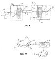
- Figure 7 illustrates the TSOP version of playback circuit 48, with 14 pins on each side of the package.
- Playback circuit 48 stores several or multiple different sound generating signals, a different signal corresponding to each one of the outputs from microprocessor 46, i.e. each of the addresses.
- a speaker 54 is mounted to heel 22 of the shoe, and electrically coupled to the control circuit, more specifically the voice playback circuit, by an electrical conductor 55 shown as a broken line in Figure 2 .
- a suitable speaker 54 is available from Panasonic under the designation "EASP3P127A.” This speaker weighs 8 grams and has a diameter of about 36 mm, with a thickness ranging from just over 2 mm, to about 4 mm at its center. Speaker 54 generates audible signals in accordance with the electrical signals received from voice playback circuit 48.
- Figure 8 is an electrical schematic illustrating the coupling of the major components of the device.
- Sensors 30 and 32, microprocessor 46 and voice playback circuit 48 are coupled between the positive and negative terminals of power supply 44.
- the positive terminal has a bias of 4.5 volts, and the negative terminal is at ground.
- Sensors 30 and 32, and any additional sensors that might be provided, are coupled in parallel, so that closure of any one of the membrane switches causes an audible output from speaker 54.
- Connections between microprocessor 46 and playback circuit 48 include eight data lines 56 for the parallel transfer of an eight-bit digital control word from the microprocessor to the playback circuit.
- lines 56 are coupled to microprocessor terminals labeled RB0-RB3 and RC0-RC3, and to provide input to terminals A0-A7 of the playback circuit.
- An enabling input is transferred from a terminal RA2 of the microprocessor to a terminal CE of the playback circuit via a line 58.
- a playback line 60 couples terminal RA1 of microprocessor 46 with input terminal P/R of playback circuit 48. Line 60 can be used in a recording function, explained in connection with Figure 17 .
- An external clock 62 is coupled to terminals XIN and XOUT of the microprocessor, for optional use.
- FIG. 9 schematically illustrates certain internal components involved in the interaction of microprocessor 46 and voice playback circuit 48.
- the microprocessor includes selection logic 64 which can be hardwired, but more preferably is provided as a computer program resident in the microprocessor.
- a memory 66 of the microprocessor includes multiple registers 68 for storing digital control words, each control word associated with a different one of several desired feedback sounds.
- the selection logic preferably is configured to operate in a random mode to select control words, but might be configured for an alternative selection mode, e.g. sequential.
- Each control word is an eight-bit digital word, and resides in one of registers 68.
- An output register 70 is coupled to the memory, to receive a selected control word for transmission to the voice playback circuit over data lines 56.
- Voice playback circuit 48 includes an input register 72 for receiving the control word.
- the control word is used to select one of multiple addresses 74 associated with digital data representing control outputs.
- data registers containing the control output data are individually associated with the addresses, which are numbered sequentially. Because the control output data for a given sound selection typically occupies more than one data register, a sequence of the data registers associated with a given sound typically is identified by its initial (lowest numbered) address, and selected on the basis of that address. Accordingly, while using eight-bit control words corresponds to 256 possible addresses, only a fraction of the available addresses (e.g. ten to twenty) actually are used for selection (random or otherwise) from memory 66 of the microprocessor.
- the selection of a particular address selects a sequence of data registers 76 associated with that address.
- the data in the selected sequence are converted to an analog signal at 77, which is provided to an analog transceiver 78, to a smoothing filter 80 and then to an amplifier 82 of the playback circuit.
- the output of amplifier 82 i.e. the control output, is an analog electrical signal.
- the analog signal is provided as an input to speaker 54, which converts the analog electrical control output to the selected sound.
- the device functions as illustrated by the flow chart in Figure 10 .
- microprocessor 46 Upon receiving a true input, microprocessor 46 at a stage 86 effects a random selection of one of its addresses, generating a signal corresponding to the selected address as indicated at 88.
- voice playback circuit 48 At stage 90, voice playback circuit 48 generates as its output an analog electrical signal corresponding to the selected address. As indicated at 92, the electrical signal is provided as an input to speaker 54, which converts the electrical signal to an audio output to generate the selected sound.
- microprocessor 46 and playback circuit 48 are used in concert to select a wide variety of sounds to be generated by speaker 54 as immediate positive feedback. This informs the player that during the kick, contact with the ball occurred at the desired contact point, or alternatively at one of several desired contact points.
- sounds can include short phrases like "Nice kick! or "Way to go!”, a short musical phrase, or simulated crowd noise, such as cheering or applause.
- These alternative sounds are randomly selected, but in each instance the intent is to provide positive reinforcement following each correct kick.
- the device can be used to provide an unpleasant sound as "negative" feedback following an improper kick.
- a sensor 94 in the form of a pressure-responsive membrane switch is mounted to toe 20 of soccer shoe 16.
- a circuit including sensor 94 incorporates power supply 44.
- microprocessor 46 and playback circuit 48 are not part of the circuit, as indicated by a conductive path 96 coupling the sensor directly to a separate playback circuit 98.
- the output of playback circuit 98 is an electrical signal to speaker 54, which causes the speaker to generate an unfavorable or negative sound, e.g., simulating a buzzer.
- a sling or cover 100 resembling a stocking without a toe or heel, is removably secured over the shoe worn by the player.
- Sling 100 supports all components of the device, eliminating the need to mount any of the components permanently to the shoe and thereby enabling use of the device with a conventional soccer shoe.
- the sling or strap When the sling or strap is secured, it positions sensors 102 and 104 at desired points of contact for kicking the soccer ball, while at the same time positioning a control circuit 106 and a speaker 108 at points where contact with the soccer ball is comparatively unlikely during normal use.
- This embodiment is advantageous from the standpoint of avoiding the need to customize or specially configure a particular soccer shoe, and transferability from one soccer shoe to another.
- components permanently mounted to the soccer shoe as in the previous embodiments, are fixed with respect to the shoe and thereby prevented from shifting relative to the shoe.
- Figure 14 illustrates an alternative embodiment device in the form of a strap arrangement 110 including a section 112 forming a forward loop, and a rearedly extending horizontal section 114.
- Section 112 supports a membrane switch or other suitable sensor 116 near the top of the loop, and supports a control circuit 118 near the bottom of the loop.
- Section 114 of the arrangement supports a membrane switch 120 and a speaker 122.
- Strap arrangement 110 can be mounted on a soccer shoe 124 having cleats 126 as illustrated in Figure 15 .
- the loop of section 112 surrounds the shoe along an area between the front and rear cleats, positioning sensor 116 along the top of the shoe and control circuit 118 along the bottom of the shoe between cleats. Meanwhile, horizontal strap section 114 positions switch 120 along the instep, and locates speaker 122 proximate the heel, or in an outstep region near the heel.
- Strap arrangement 110 can be formed with elastic material, with the loop formed by strap section 112 permanently closed and installed by stretching the strap as it is pulled over the toe of shoe 124.
- Figure 16 illustrates an alternative strap arrangement 128 in which a forward strap 130 may or may not be formed of an elastic material, but in any event is not formed as a closed loop. Rather, strap 130 has free ends, typically located on the side of a shoe 132, releasably coupled with one another with closure material to form a closed loop.
- a horizontal strap 134 can form a rearedly extending loop, open at the front, as before.
- Strap arrangement 128 is particularly well-suited for use with shoes like shoe 132 having a continuous sole 136. To facilitate mounting the strap arrangement, a portion of sole 136 is cut away to provide a tunnel 138, through which strap 130 is threaded by one of its free ends, after which the ends are secured on the outstep side of shoe 132.
- strap 130 positions a sensor 140 at the top of the shoe, and locates a control circuit 142 within the tunnel.
- Strap 134 locates a sensor 144 at the instep, and locates a speaker 146 at or near the heel as
- control circuit and the conductive paths between the control circuit and the sensors and speaker, as one or more flexible printed circuits.
- Figure 17 illustrates a recording feature of an alternative embodiment control circuit 148, including a microprocessor 150 and a voice playback circuit 152 coupled as previously described.
- the microprocessor and playback circuit are provided with additional components to enable users to record sounds for future selection and playback.
- the additional components include a microphone 154 for converting sounds into analog electrical signals.
- the analog signal corresponding to each input sound is provided from the microphone to a circuit 156 that samples the signal to generate digital data representing the analog electrical signal.
- the digital data are stored in one or more data registers 158 of playback circuit 152.
- the microphone is enabled by a control input 160, which also provides an input 162 to microprocessor 150 for storing an address associated with the incoming data, and an input 164 to playback circuit 152 to associate the added address with the added data.
- a soccer player is given immediate feedback which encourages that player to improve his or her kicking technique.
- the player's interest in improvement is maintained and heightened, due to the variety of sounds provided as positive feedback.
- the circuit components can be configured and arranged to minimize any impact on the appearance or performance of the shoe.
Abstract
Description
- This invention relates to apparatus designed to provide instantaneous feedback to athletes in training. More particularly, the invention is directed to a device for generating audible or other sensible responses to certain kicking techniques and approaches used by soccer players.
- One of the challenges confronting relatively inexperienced soccer players is the need to develop a proper kicking technique. In general, inexperienced players need to overcome two tendencies. The first is to rely on a favored or stronger foot, typically the right foot, for kicking the ball. The second tendency concerns the point of contact with the soccer ball. Inexperienced players tend to rely exclusively on the toe of the shoe. Coaches and other instructors spend considerable time and effort teaching players to kick more frequently with the "weaker" foot, and to increase their use of more effective contact points for better strength and accuracy, e.g., the top of the foot (typically the lace area) for forward power kicking, the arch or instep for sideways kicking, and as players gain experience, the "outside" part of the foot opposite the arch.
- A variety of devices have been proposed for assisting soccer players in developing better kicking techniques. For example,
U.S. Patent No. 5,947,845 (Canelas ) andU.S. Patent No. 3,866,909 (DeSantis ) illustrate markers that visually indicate preferred areas of the shoe used for kicking the soccer ball. If desired, the soccer ball also can be marked to indicate preferred areas of contact when kicking. - Training devices have been proposed to provide audible feedback.
U.S. Patent No. 5,433,437 (Dudley ) andU.S. Patent No. 4,711,043 (Johnson et. al) disclose devices mounted on soccer shoes and capable of emitting sounds in response to contact with the soccer ball. The devices can include hollow bulbs with reed whistles, domed cylinders, and resilient molded plastic squeakers. These devices have the advantage of providing instantaneous feedback. If the point of contact between the shoe and soccer ball coincides with the desired location, i.e. where the device is mounted, the pressure from the ball will squeeze the device and produce the sound. If a point of contact is elsewhere, the device does not generate the sound. - Although the instantaneous feedback of the audible devices is beneficial in teaching kicking techniques, the devices protrude outwardly from the shoe, to the extent of detracting from the appearance of the shoe and unduly shifting the point of contact with the ball away from the surface of the shoe. This tends to limit the practical placement of these devices, primarily to the upper foot or lace area as shown in the patents. The devices further are limited in the sense that each device generates a single, characteristic sound. At the same time, the characteristic sound is subject to undesirable inconsistencies arising from the variety of angles and levels of force at which the ball is kicked.
- Published international application
WO 98/42220 -
US Patent No. 5,765,300 discloses a shoe activated sound synthesizer that enables movement of a shoe to be translated into audible sounds. Trigger keys, such as piezoelectric transducers are disposed in the sole of the shoe. As the shoe flexes during use by the wearer, a signal is generated indicative of the degree of flexure experienced by the piezoelectric element. The signals generated by the piezoelectric elements are transmitted to a separate control box worn by the user. A sound synthesizer within the control box broadcasts a specific sound corresponding to the triggered piezoelectric element. - To overcome these deficiencies, there is provided an athletic training apparatus for encouraging proper ball handling techniques by a user, the athletic training apparatus comprising:
- a pressure sensor disposed in relation to the foot of the user, said pressure sensor being adapted to generate a sensor output signal when subjected to pressure from contact with a ball;
- a control circuit operatively coupled to said pressure sensor for receiving said sensor output signal, said control circuit being adapted to select one of a plurality of control output signals in response to said sensor output signal; and
- a signal generator operatively coupled to said control circuit for receiving said control output signals, said signal generator being adapted to generate signals that are sensible by the user so as to indicate to the user whether the contact with the ball was a proper and/or improper ball handling technique.
- Providing separate sensing and signaling components, and operatively coupling these components at least in part with an electrical sensor signal from the sensing component, affords several advantages not found in conventional mechanical audible feed-back devices. One of these is the variety of audio feedback available. Instead of the characteristic sound of a hollow bulb or reed whistle, the training device can generate spoken phrases, simulated crowd noise and musical phrases. At the same time, the audible feedback can be more consistent. For example, a musical phrase can be generated with a consistent tempo and volume, regardless of whether a ball is kicked with different levels of impact or at different angles. The present invention provides devices that are smaller, less obtrusive, more readily built into or otherwise attached to the shoe, and capable of providing a variety of audible responses when contacted by the soccer ball during a kick. The devices have minimal impact on the appearance of the shoe. Further, due to their size and selected positioning on the shoe, the components of the device have minimal impact on performance. The player wearing the shoe is able to kick the soccer ball in the same manner, and with the same result as if that player were wearing an ordinary shoe.
- The components of the device afford several options, suited to different teaching objectives. For example, components might be mounted only on the left shoe, with a player whose "weaker" foot is the left foot thereby being encouraged to kick with the left foot more frequently. Several sensors can be mounted on the same shoe if desired, in different selected locations, such as the instep and the lace or top area of the shoe. Typically the components are selected to generate positive or up-beat sounds, e.g., encouraging words or a short musical phrase. However, if desired, a sensor can be placed at yet another selected location on the shoe, e.g., the toe, where the object is to discourage the player from using that location as a point of contact when kicking the ball. In this event, contact preferably simulates a buzzer or other less pleasant sound.
- In one preferred version of the invention, the components are built into or otherwise permanently secured to the soccer shoe. In alternative embodiments, straps or closure material (e.g., Velcro) can be used to mount certain components. In either event, players making proper contact when kicking the ball are provided with immediate feedback in the form of the resulting audible signals, and thereby are encouraged to develop sound kicking techniques.
- In one preferred embodiment, the selecting component comprises a microprocessor having a memory for storing different control words. Each control word is associated with a different one of the control outputs. The microprocessor incorporates selection logic for selecting one of the control words in response to receiving the sensor signal. The selecting component further includes an audio playback circuit coupled to the microprocessor. The playback circuit is adapted to generate the control output associated with the selected control word, and provide the control output to the signaling component.
- The apparatus further can include a recording component for storing a further control word to the microprocessor memory, for storing data representing a further control output to the audio playback device, and for associating the further control output with the further control word, whereby the playback device will generate the further control output in response to receiving the further control word. Using this feature, users can load their own, customized sounds into the apparatus for later playback in response to properly executed kicks.
- Thus in accordance with the present invention, a shoe for soccer or any other sport can be configured to generate a variety of virtually instantaneous feedback signals in response to proper kicking techniques, or improper techniques as well if desired. The sensing components, signaling components and selection components when the selection feature is employed, are small and unobtrusive compared to conventional mechanical audio feedback components. Accordingly the invention provides increased flexibility in locating sensing components. Further flexibility arises from the options of mounting the components permanently to the shoe, or providing a cover or strap arrangement to removably position the components with respect to the shoe. In any event, players are encouraged to increase the use of the "weaker" foot, and employ better kicking techniques.
- For a further understanding of the preceding features and advantages, reference is made to the following detailed description and to the drawings, in which:
-
Figure 1 is a prospective view of a soccer shoe equipped with an audible signal generating device constructed in accordance with the present invention; -
Figure 2 is a bottom view of the soccer shoe; -
Figure 3 is an end view of the soccer shoe; -
Figure 4 is a diagrammatic view of a control circuit of the signal generating device; -
Figure 5 is a plan view of a microprocessor of the control circuit, in the form of a dual-in-line package; -
Figure 6 is a plan view of an alternative microprocessor in the form of a "small outline package;" -
Figure 7 is a plan view of a voice playback segment of the control circuit in the form of a "thin small outline package;" -
Figure 8 is an electrical schematic illustrating the major components of the device; -
Figure 9 is a schematic view of the microprocessor and voice playback circuit; -
Figure 10 is a flow chart illustrating operation of the device; -
Figure 11 is a schematic view of an alternative audio feedback device constructed according to the present invention; -
Figures 12 and 13 illustrate an alternative embodiment device in the form of a cover; -
Figure 14 illustrates a further alternative embodiment device in the form of a strap arrangement; -
Figure 15 illustrates the strap arrangement attached to a soccer shoe; -
Figure 16 illustrates the strap arrangement attached to a tennis shoe; and -
Figure 17 is a schematic view showing part of an alternative embodiment control circuit incorporating a recording feature. - Turning to the drawings,
Figures 1, 2 and 3 show asoccer shoe 16, specifically the left shoe, equipped with an audible signal generating device in accordance with the present invention. The device can be conveniently thought of as a pressure-responsive audible signal feedback system, with the following components: one or more pressure-responsive sensors; a control circuit receiving signals from each sensor and, in response, generating an output signal; and a speaker receiving the output signal from the control circuit and generating a sound based on that output. -
Soccer shoe 16 includes an upper 18 with atoe 20, aheel 22, and aninstep 24 positioned along the arch of the player wearing the shoe. The upper is secured to a sole 26 that has a substantial thickness, e.g., one-half inch (13 mm) over the length of the shoe. The sole may include spikes formed along the bottom, although a shoe without spikes is shown in these figures. A portion of the upper has laces, indicated at 28. - Two sensors are mounted to shoe 16: a
sensor 30 at the instep or arch area, and asensor 32 at the top of the shoe over the laced area, mounted to a stretchable strap 33 or other suitable support.Sensors -
Sensors - As seen in
Figure 2 , the device includes acontrol circuit 34 embedded into sole 26. The sole includes aforward region 36 corresponding to the ball of the foot, and aheel region 38. The control circuit preferably is embedded into the sole at amedial region 40 betweenregions - As seen in
Figure 4 ,control circuit 34 can be provided in the form of aflexible circuit board 42 including several circuit components, which are electrically coupled to one another by thin film printed circuitry. The components include apower supply 44 consisting of several batteries for providing power at a suitable level, e.g., about 5 volts. The other major components of this circuit include amicroprocessor 46 and avoice playback circuit 48. - As indicated by broken lines at 50 and 52 respectively, wires or other electrically conductive paths connect
sensors - One suitable microprocessor is available from Winbond Electronics Corporation of San Jose, California, under the designation "W741E203." The microprocessor can be provided in the form of a dual-in-line package (PDIP) having a length of about 23 nun, a width of about 8 mm, and a thickness of less than 4 mm. Alternatively the microprocessor is provided in the form of an unpackaged die to considerably reduce the size of this component. In either event, the microprocessor operates on a very low current, randomly selecting one of several or multiple addresses in response to receiving the signal generated when one of sensors/switches 30 and 32 is closed. The microprocessor output is a signal uniquely corresponding to the selected address.
-
Figure 5 showsmicroprocessor 46 in the form of a dual-in-line package including a twenty-pin configuration, which presently is preferred.Figure 6 illustrates an alternative microprocessor 46a in a "small outline package" configuration, again with twenty pins. - A suitable version of
voice playback circuit 48 is available from Winbond Electronics Corporation of San Jose, California, under the designation "ISD 2560." The playback circuit is provided in the form of a semiconductor chip having a length of about 10 mm, a width of about 5 mm and a 0.5 mm thickness. Alternatively, the playback circuit is provided in the form of a "thin small outline package" (TSOP) of about 13 mm by 8 mm by 1 mm. In either event,playback circuit 48 is readily incorporated into the control circuitry and embedded into sole 26 as shown.Figure 7 illustrates the TSOP version ofplayback circuit 48, with 14 pins on each side of the package. -
Playback circuit 48 stores several or multiple different sound generating signals, a different signal corresponding to each one of the outputs frommicroprocessor 46, i.e. each of the addresses. - As seen in
Figures 2 and 3 , aspeaker 54 is mounted toheel 22 of the shoe, and electrically coupled to the control circuit, more specifically the voice playback circuit, by anelectrical conductor 55 shown as a broken line inFigure 2 . Asuitable speaker 54 is available from Panasonic under the designation "EASP3P127A." This speaker weighs 8 grams and has a diameter of about 36 mm, with a thickness ranging from just over 2 mm, to about 4 mm at its center.Speaker 54 generates audible signals in accordance with the electrical signals received fromvoice playback circuit 48. -
Figure 8 is an electrical schematic illustrating the coupling of the major components of the device.Sensors microprocessor 46 andvoice playback circuit 48 are coupled between the positive and negative terminals ofpower supply 44. The positive terminal has a bias of 4.5 volts, and the negative terminal is at ground.Sensors speaker 54. - Connections between
microprocessor 46 andplayback circuit 48 include eightdata lines 56 for the parallel transfer of an eight-bit digital control word from the microprocessor to the playback circuit. Specifically, lines 56 are coupled to microprocessor terminals labeled RB0-RB3 and RC0-RC3, and to provide input to terminals A0-A7 of the playback circuit. An enabling input is transferred from a terminal RA2 of the microprocessor to a terminal CE of the playback circuit via aline 58. Aplayback line 60 couples terminal RA1 ofmicroprocessor 46 with input terminal P/R ofplayback circuit 48.Line 60 can be used in a recording function, explained in connection withFigure 17 . Anexternal clock 62 is coupled to terminals XIN and XOUT of the microprocessor, for optional use. -
Figure 9 schematically illustrates certain internal components involved in the interaction ofmicroprocessor 46 andvoice playback circuit 48. The microprocessor includesselection logic 64 which can be hardwired, but more preferably is provided as a computer program resident in the microprocessor. Amemory 66 of the microprocessor includesmultiple registers 68 for storing digital control words, each control word associated with a different one of several desired feedback sounds. The selection logic preferably is configured to operate in a random mode to select control words, but might be configured for an alternative selection mode, e.g. sequential. Each control word is an eight-bit digital word, and resides in one of registers 68. Anoutput register 70 is coupled to the memory, to receive a selected control word for transmission to the voice playback circuit over data lines 56. -
Voice playback circuit 48 includes aninput register 72 for receiving the control word. The control word is used to select one ofmultiple addresses 74 associated with digital data representing control outputs. In a preferred version ofplayback circuit 48, data registers containing the control output data are individually associated with the addresses, which are numbered sequentially. Because the control output data for a given sound selection typically occupies more than one data register, a sequence of the data registers associated with a given sound typically is identified by its initial (lowest numbered) address, and selected on the basis of that address. Accordingly, while using eight-bit control words corresponds to 256 possible addresses, only a fraction of the available addresses (e.g. ten to twenty) actually are used for selection (random or otherwise) frommemory 66 of the microprocessor. - In any event, the selection of a particular address selects a sequence of data registers 76 associated with that address. The data in the selected sequence are converted to an analog signal at 77, which is provided to an
analog transceiver 78, to a smoothingfilter 80 and then to an amplifier 82 of the playback circuit. The output of amplifier 82, i.e. the control output, is an analog electrical signal. The analog signal is provided as an input tospeaker 54, which converts the analog electrical control output to the selected sound. - The device functions as illustrated by the flow chart in
Figure 10 . - When a kick of the soccer ball results in pressure at one of the membrane switches sufficient to close it, the output of a
pressure threshold stage 84 is true. Otherwise the output is false, and no signal is provide to the microprocessor. - Upon receiving a true input,
microprocessor 46 at astage 86 effects a random selection of one of its addresses, generating a signal corresponding to the selected address as indicated at 88. Atstage 90,voice playback circuit 48 generates as its output an analog electrical signal corresponding to the selected address. As indicated at 92, the electrical signal is provided as an input tospeaker 54, which converts the electrical signal to an audio output to generate the selected sound. - In accordance with the present invention,
microprocessor 46 andplayback circuit 48 are used in concert to select a wide variety of sounds to be generated byspeaker 54 as immediate positive feedback. This informs the player that during the kick, contact with the ball occurred at the desired contact point, or alternatively at one of several desired contact points. Such sounds can include short phrases like "Nice kick!" or "Way to go!", a short musical phrase, or simulated crowd noise, such as cheering or applause. These alternative sounds are randomly selected, but in each instance the intent is to provide positive reinforcement following each correct kick. - According to an alternative embodiment, the device can be used to provide an unpleasant sound as "negative" feedback following an improper kick. As shown schematically in
Figure 11 , asensor 94 in the form of a pressure-responsive membrane switch is mounted totoe 20 ofsoccer shoe 16. Acircuit including sensor 94 incorporatespower supply 44. However,microprocessor 46 andplayback circuit 48 are not part of the circuit, as indicated by a conductive path 96 coupling the sensor directly to aseparate playback circuit 98. The output ofplayback circuit 98 is an electrical signal tospeaker 54, which causes the speaker to generate an unfavorable or negative sound, e.g., simulating a buzzer. - According to another embodiment of the invention shown in
Figures 12 and 13 , a sling or cover 100, resembling a stocking without a toe or heel, is removably secured over the shoe worn by the player.Sling 100 supports all components of the device, eliminating the need to mount any of the components permanently to the shoe and thereby enabling use of the device with a conventional soccer shoe. When the sling or strap is secured, it positionssensors control circuit 106 and aspeaker 108 at points where contact with the soccer ball is comparatively unlikely during normal use. This embodiment is advantageous from the standpoint of avoiding the need to customize or specially configure a particular soccer shoe, and transferability from one soccer shoe to another. On the other hand, components permanently mounted to the soccer shoe, as in the previous embodiments, are fixed with respect to the shoe and thereby prevented from shifting relative to the shoe. -
Figure 14 illustrates an alternative embodiment device in the form of a strap arrangement 110 including asection 112 forming a forward loop, and a rearedly extendinghorizontal section 114.Section 112 supports a membrane switch or othersuitable sensor 116 near the top of the loop, and supports acontrol circuit 118 near the bottom of the loop.Section 114 of the arrangement supports amembrane switch 120 and aspeaker 122. - Strap arrangement 110 can be mounted on a
soccer shoe 124 havingcleats 126 as illustrated inFigure 15 . The loop ofsection 112 surrounds the shoe along an area between the front and rear cleats,positioning sensor 116 along the top of the shoe andcontrol circuit 118 along the bottom of the shoe between cleats. Meanwhile,horizontal strap section 114 positions switch 120 along the instep, and locatesspeaker 122 proximate the heel, or in an outstep region near the heel. Strap arrangement 110 can be formed with elastic material, with the loop formed bystrap section 112 permanently closed and installed by stretching the strap as it is pulled over the toe ofshoe 124. -
Figure 16 illustrates an alternative strap arrangement 128 in which a forward strap 130 may or may not be formed of an elastic material, but in any event is not formed as a closed loop. Rather, strap 130 has free ends, typically located on the side of a shoe 132, releasably coupled with one another with closure material to form a closed loop. Ahorizontal strap 134 can form a rearedly extending loop, open at the front, as before. Strap arrangement 128 is particularly well-suited for use with shoes like shoe 132 having a continuous sole 136. To facilitate mounting the strap arrangement, a portion of sole 136 is cut away to provide atunnel 138, through which strap 130 is threaded by one of its free ends, after which the ends are secured on the outstep side of shoe 132. Thus secured, strap 130 positions asensor 140 at the top of the shoe, and locates acontrol circuit 142 within the tunnel.Strap 134 locates asensor 144 at the instep, and locates a speaker 146 at or near the heel as before. - In the embodiments of
Figures 12-16 it is advantageous to configure the control circuit, and the conductive paths between the control circuit and the sensors and speaker, as one or more flexible printed circuits. -
Figure 17 illustrates a recording feature of an alternative embodiment control circuit 148, including a microprocessor 150 and a voice playback circuit 152 coupled as previously described. The microprocessor and playback circuit are provided with additional components to enable users to record sounds for future selection and playback. The additional components include amicrophone 154 for converting sounds into analog electrical signals. The analog signal corresponding to each input sound is provided from the microphone to acircuit 156 that samples the signal to generate digital data representing the analog electrical signal. The digital data are stored in one ormore data registers 158 of playback circuit 152. The microphone is enabled by acontrol input 160, which also provides aninput 162 to microprocessor 150 for storing an address associated with the incoming data, and aninput 164 to playback circuit 152 to associate the added address with the added data. - Regardless of the embodiment employed, a soccer player is given immediate feedback which encourages that player to improve his or her kicking technique. The player's interest in improvement is maintained and heightened, due to the variety of sounds provided as positive feedback. The circuit components can be configured and arranged to minimize any impact on the appearance or performance of the shoe.
Claims (9)
- An athletic training apparatus (16, 33, 100, 110 or 128) for encouraging proper ball handling techniques by a user, the athletic training apparatus comprising:a pressure sensor (30, 32, 94, 102, 104, 116, 120, 140 or 144) disposed in relation to the foot of the user, said pressure sensor being adapted to generate a sensor output signal when subjected to pressure from contact with a ball;a control circuit (34, 106, 118, 142 or 148) operatively coupled to said pressure sensor for receiving said sensor output signal, said control circuit being adapted to select one of a plurality of control output signals in response to said sensor output signal; anda signal generator (54,108,122 or 146) operatively coupled to said control circuit for receiving said control output signals, said signal generator being adapted to generate signals that are sensible by the user so as to indicate to the user whether the contact with the ball was a proper and/or improper ball handling technique.
- The athletic training apparatus of Claim 1, wherein said pressure sensor (3 0, 32, 94, 102, 104, 116, 120, 140 or 144), said control circuit (34, 106, 118, 142 or 148) and said signal generator (54, 108, 122 or 146) are integral with a shoe.
- The athletic training apparatus of Claim 1, wherein said pressure sensor (30, 32, 94, 102, 104, 116, 120, 140 or 144), said control circuit (34, 106, 118, 142 or 148) and said signal generator (54, 108, 122 or 146) are securable (33, 100, 110 or 128) onto a shoe.
- The athletic training apparatus of Claim 1, wherein said generated user sensible signal is an audible signal.
- The athletic training apparatus of Claim 4, wherein said control circuit (34, 106, 118, 142 or 148) includes sound recording circuitry (154,156, 158, 160, 162, 164) to record a plurality of different sounds and memory (66) for storing said plurality of different recorded sounds.
- The athletic training apparatus of Claim 5, wherein said control circuit (34, 106, 118, 142 or 148) includes playback circuitry (48, 98 or 154) in which the stored recorded sounds are associated with said sensor output signals for selective playback as user sensible signals by said signal generator (54, 108, 122 or 146).
- The athletic training apparatus of Claim 1, wherein said pressure sensor (30, 32, 94, 102, 104, 116, 120, 140 or 144) is disposed at proximate the instep (24) of the user's foot.
- The athletic training apparatus of Claim 1, wherein said pressure sensor (30, 32, 94, 102, 104, 116, 120, 140 or 144) is disposed proximate the top of the user's foot.
- The athletic training apparatus of Claim 7, further including another pressure sensor (30, 32, 94, 102, 104, 116, 120, 140 or 144) disposed at approximately the top of the user's foot, said another pressure sensor operatively coupled to said control circuit (34, 106, 118, 142 or 148) for providing another sensor output signal to said control circuit wherein said control circuit selects another one of said plurality of control output signals in response to said another sensor output signal.
Applications Claiming Priority (3)
| Application Number | Priority Date | Filing Date | Title |
|---|---|---|---|
| US30076401P | 2001-06-25 | 2001-06-25 | |
| US300764P | 2001-06-25 | ||
| PCT/US2002/020233 WO2003000355A1 (en) | 2001-06-25 | 2002-06-25 | Training shoe for soccer |
Publications (3)
| Publication Number | Publication Date |
|---|---|
| EP1409089A1 EP1409089A1 (en) | 2004-04-21 |
| EP1409089A4 EP1409089A4 (en) | 2004-10-27 |
| EP1409089B1 true EP1409089B1 (en) | 2008-07-30 |
Family
ID=23160483
Family Applications (1)
| Application Number | Title | Priority Date | Filing Date |
|---|---|---|---|
| EP02749664A Expired - Lifetime EP1409089B1 (en) | 2001-06-25 | 2002-06-25 | Training shoe for soccer |
Country Status (9)
| Country | Link |
|---|---|
| US (1) | US6808462B2 (en) |
| EP (1) | EP1409089B1 (en) |
| JP (1) | JP2005507678A (en) |
| CN (1) | CN1246057C (en) |
| AT (1) | ATE402746T1 (en) |
| CA (1) | CA2451598A1 (en) |
| DE (1) | DE60227957D1 (en) |
| MX (1) | MXPA04000058A (en) |
| WO (1) | WO2003000355A1 (en) |
Families Citing this family (67)
| Publication number | Priority date | Publication date | Assignee | Title |
|---|---|---|---|---|
| FR2846524A1 (en) * | 2002-10-31 | 2004-05-07 | Jean Francois Perez | Shoe design, e.g. football shoe, used for educating user to perfect a perfect kick of the ball, has unit for detecting impact of ball on certain delimited zones on shoe |
| US6955094B1 (en) * | 2003-07-18 | 2005-10-18 | Cleveland Medical Devices Inc. | Sensor for measuring shear forces |
| DE102004045176B4 (en) | 2004-09-17 | 2011-07-21 | Adidas International Marketing B.V. | bladder |
| US20060089213A1 (en) * | 2004-10-12 | 2006-04-27 | Snyder Gregory P | Ball control training device |
| US20080261727A1 (en) * | 2004-10-12 | 2008-10-23 | Snyder Gregory P | Indoor/outdoor ball control training device |
| GB0506297D0 (en) * | 2005-03-29 | 2005-05-04 | Nugent Richard J J | Sports apparatus |
| DE102005014709C5 (en) | 2005-03-31 | 2011-03-24 | Adidas International Marketing B.V. | shoe |
| US7404263B2 (en) * | 2006-01-11 | 2008-07-29 | Bbc International, Llc | Footwear with force sensing device |
| US20070227047A1 (en) * | 2006-03-29 | 2007-10-04 | Ahmed Zaza | Instructional soccer shoes, training aids attachable to soccer shoes, and related methods |
| US7607243B2 (en) | 2006-05-03 | 2009-10-27 | Nike, Inc. | Athletic or other performance sensing systems |
| US7426873B1 (en) | 2006-05-04 | 2008-09-23 | Sandia Corporation | Micro electro-mechanical system (MEMS) pressure sensor for footwear |
| US7788828B2 (en) * | 2006-05-10 | 2010-09-07 | Krouse Wayne F | Active shoe cleat system |
| US7997007B2 (en) * | 2006-09-15 | 2011-08-16 | Early Success, Inc. | Stimulus training system and apparatus to effectuate therapeutic treatment |
| WO2008042765A1 (en) * | 2006-09-29 | 2008-04-10 | Admir Dado Kantarevic | Athletic equipment including a health and/or impact sensor |
| US20080098811A1 (en) * | 2006-10-25 | 2008-05-01 | Marware, Inc. | Sensor case and method for attaching a sensor case to a shoe |
| US20080153632A1 (en) * | 2006-12-20 | 2008-06-26 | Flores Matthew F | Method and apparatus for ball kicking practice |
| US20080185799A1 (en) * | 2007-02-05 | 2008-08-07 | Weisiger Audrey K | Alert actuation device for body alignment |
| US20080216593A1 (en) * | 2007-02-22 | 2008-09-11 | Jacobsen Stephen C | Device for promoting toe-off during gait |
| US20090077832A1 (en) * | 2007-09-26 | 2009-03-26 | David Flint | Soccer Training Shoe Cover and Method of Use |
| WO2009079851A1 (en) * | 2007-12-21 | 2009-07-02 | Cypress Semiconductor Technology (Shanghai) Co., Ltd. | Finger position sensing for handheld equipment |
| US8814713B2 (en) | 2007-12-31 | 2014-08-26 | Cypress Semiconductor Corporation | Finger position sensing for handheld sports equipment |
| US20090178305A1 (en) * | 2008-01-16 | 2009-07-16 | Karen Teresa Maxwell | Footwear for use in connection with teaching |
| US10070680B2 (en) | 2008-06-13 | 2018-09-11 | Nike, Inc. | Footwear having sensor system |
| US9549585B2 (en) | 2008-06-13 | 2017-01-24 | Nike, Inc. | Footwear having sensor system |
| EP3087858B1 (en) * | 2008-06-13 | 2021-04-28 | NIKE Innovate C.V. | Footwear having sensor system |
| US9002680B2 (en) * | 2008-06-13 | 2015-04-07 | Nike, Inc. | Foot gestures for computer input and interface control |
| US20100115799A1 (en) * | 2008-11-13 | 2010-05-13 | Brady Welter | Shoe Apparatus |
| US8616892B2 (en) | 2009-04-02 | 2013-12-31 | Nike, Inc. | Training system for an article of footwear with a traction system |
| US8632342B2 (en) | 2009-05-28 | 2014-01-21 | Nike, Inc. | Training system for an article of footwear |
| US8573981B2 (en) | 2009-05-29 | 2013-11-05 | Nike, Inc. | Training system for an article of footwear with a ball control portion |
| US8529267B2 (en) * | 2010-11-01 | 2013-09-10 | Nike, Inc. | Integrated training system for articles of footwear |
| EP2638491B1 (en) | 2010-11-10 | 2022-10-05 | NIKE Innovate C.V. | Systems and methods for time-based athletic activity measurement and display |
| WO2013028217A2 (en) * | 2010-12-18 | 2013-02-28 | Paul Gallagher | Soccer ball contacting zones training aids |
| KR101853239B1 (en) | 2011-02-17 | 2018-04-27 | 나이키 이노베이트 씨.브이. | Location mapping |
| US9381420B2 (en) | 2011-02-17 | 2016-07-05 | Nike, Inc. | Workout user experience |
| KR101896204B1 (en) | 2011-02-17 | 2018-09-07 | 나이키 이노베이트 씨.브이. | Footwear having sensor system |
| CA2827687C (en) | 2011-02-17 | 2016-12-20 | Nike International Ltd. | Footwear having sensor system |
| US8739639B2 (en) | 2012-02-22 | 2014-06-03 | Nike, Inc. | Footwear having sensor system |
| US20130213147A1 (en) | 2012-02-22 | 2013-08-22 | Nike, Inc. | Footwear Having Sensor System |
| US11071344B2 (en) | 2012-02-22 | 2021-07-27 | Nike, Inc. | Motorized shoe with gesture control |
| US11684111B2 (en) | 2012-02-22 | 2023-06-27 | Nike, Inc. | Motorized shoe with gesture control |
| US20130213146A1 (en) | 2012-02-22 | 2013-08-22 | Nike, Inc. | Footwear Having Sensor System |
| US9241539B1 (en) | 2012-06-29 | 2016-01-26 | Jeffrey Keswin | Shoelace tightening method and apparatus |
| US9043004B2 (en) | 2012-12-13 | 2015-05-26 | Nike, Inc. | Apparel having sensor system |
| US11006690B2 (en) | 2013-02-01 | 2021-05-18 | Nike, Inc. | System and method for analyzing athletic activity |
| US10926133B2 (en) | 2013-02-01 | 2021-02-23 | Nike, Inc. | System and method for analyzing athletic activity |
| US9743861B2 (en) | 2013-02-01 | 2017-08-29 | Nike, Inc. | System and method for analyzing athletic activity |
| DE102013202485B4 (en) | 2013-02-15 | 2022-12-29 | Adidas Ag | Ball for a ball sport |
| US9279734B2 (en) | 2013-03-15 | 2016-03-08 | Nike, Inc. | System and method for analyzing athletic activity |
| US10260968B2 (en) | 2013-03-15 | 2019-04-16 | Nano Composite Products, Inc. | Polymeric foam deformation gauge |
| KR20150131241A (en) | 2013-03-15 | 2015-11-24 | 브라이엄 영 유니버시티 | Composite material used as a strain gauge |
| TW201509381A (en) * | 2013-09-05 | 2015-03-16 | Homeway Technology Co Ltd | Foot correction service system |
| CA2945792C (en) * | 2014-04-14 | 2021-02-23 | Flyclip Llc | Lace adjuster assembly including feedback assembly for use in visualizing and measuring athletic performance |
| GB201412701D0 (en) * | 2014-07-17 | 2014-09-03 | Stanfield Simon P F And Stanfield Lindsay A T | Sports shoe |
| US10058147B2 (en) | 2014-09-18 | 2018-08-28 | Safe Secure Sports, Llc | Athletic shoe with an attached moveable cleat |
| US10405779B2 (en) * | 2015-01-07 | 2019-09-10 | Nano Composite Products, Inc. | Shoe-based analysis system |
| US10222283B2 (en) * | 2015-04-08 | 2019-03-05 | Smart Skin Technologies Inc. | Systems and methods of providing automated feedback to a user using a shoe insole assembly |
| USD761677S1 (en) | 2015-05-14 | 2016-07-19 | JANB Holdings | Foot-mountable sensor and feedback device |
| WO2017031296A1 (en) | 2015-08-18 | 2017-02-23 | Mark Rash | Method and shoe for facilitating learning for children and for adults recovering from strokes, head injuries and other head trauma |
| US20170200351A1 (en) * | 2016-01-11 | 2017-07-13 | Robert Grubba | Sound-Producing Shoe Including Impact and Proximity Detections |
| CN105795579A (en) * | 2016-05-06 | 2016-07-27 | 京东方科技集团股份有限公司 | Intelligent football shoe, terminal and intelligent analyzing system |
| US10758801B1 (en) * | 2017-02-11 | 2020-09-01 | Focal Wellness, Inc. | Method and system for proper kicking technique |
| EP3738506A1 (en) * | 2017-03-07 | 2020-11-18 | Motionize Israel Ltd. | Footwear sensor mounting system |
| US10176691B2 (en) * | 2017-06-07 | 2019-01-08 | Rachanee L. Smoak | Tracking and monitoring system |
| KR102051303B1 (en) * | 2018-03-12 | 2019-12-03 | 김진환 | System for football shooting training and posture correction |
| GB201918736D0 (en) * | 2019-12-18 | 2020-01-29 | Prescott Matthew Harry | Sports training aid and method of use |
| US11006860B1 (en) | 2020-06-16 | 2021-05-18 | Motionize Israel Ltd. | Method and apparatus for gait analysis |
Family Cites Families (18)
| Publication number | Priority date | Publication date | Assignee | Title |
|---|---|---|---|---|
| US3866909A (en) | 1973-04-09 | 1975-02-18 | Militana Salvatore G | Protective garment for karate with force indicating members thereon |
| US4204346A (en) * | 1978-01-23 | 1980-05-27 | Fugere Albert L | Training shoe for soccer |
| JPS60200120A (en) * | 1984-03-24 | 1985-10-09 | Matsushita Electric Works Ltd | Pedometer |
| US4711043A (en) | 1986-10-01 | 1987-12-08 | Johnson Dennis M | Training device for kicking a football or soccer ball |
| US5216827A (en) * | 1989-12-01 | 1993-06-08 | Yoav Cohen | Soccer training shoe |
| US5437289A (en) * | 1992-04-02 | 1995-08-01 | Liverance; Howard L. | Interactive sports equipment teaching device |
| US5471405A (en) * | 1992-11-13 | 1995-11-28 | Marsh; Stephen A. | Apparatus for measurement of forces and pressures applied to a garment |
| US5290043A (en) * | 1993-05-14 | 1994-03-01 | Blagoje Vidinic | Game for practicing soccer skills |
| US5894686A (en) * | 1993-11-04 | 1999-04-20 | Lumitex, Inc. | Light distribution/information display systems |
| US5644858A (en) * | 1993-12-02 | 1997-07-08 | L.A. Gear, Inc. | Inertially responsive footwear lights |
| US5483759A (en) * | 1994-02-01 | 1996-01-16 | Genesco Inc. | Footwear or other products |
| US5615111A (en) * | 1994-05-23 | 1997-03-25 | Solefound, Inc. | Record and playback means for footwear |
| US5433437A (en) | 1994-07-01 | 1995-07-18 | Dudley; Peter B. | Foot mounted sounding soccer training device |
| US5765300A (en) * | 1995-12-28 | 1998-06-16 | Kianka; Michael | Shoe activated sound synthesizer device |
| US5897446A (en) * | 1996-04-23 | 1999-04-27 | Wiseman; Katherine O. | Soccer training aid |
| AU2341697A (en) * | 1997-03-21 | 1998-10-20 | Sbh, Inc. | Record and playback means for footwear |
| US5947845A (en) | 1997-04-15 | 1999-09-07 | Canelas; Carlos | Combination ball and shoes |
| US6315571B1 (en) * | 1998-11-13 | 2001-11-13 | Chosun International, Inc. | Slipper with musical and rhythmic stimulation |
-
2002
- 2002-06-25 JP JP2003506996A patent/JP2005507678A/en active Pending
- 2002-06-25 EP EP02749664A patent/EP1409089B1/en not_active Expired - Lifetime
- 2002-06-25 DE DE60227957T patent/DE60227957D1/en not_active Expired - Lifetime
- 2002-06-25 AT AT02749664T patent/ATE402746T1/en not_active IP Right Cessation
- 2002-06-25 WO PCT/US2002/020233 patent/WO2003000355A1/en active Application Filing
- 2002-06-25 US US10/179,501 patent/US6808462B2/en not_active Expired - Fee Related
- 2002-06-25 MX MXPA04000058A patent/MXPA04000058A/en active IP Right Grant
- 2002-06-25 CN CNB028166612A patent/CN1246057C/en not_active Expired - Fee Related
- 2002-06-25 CA CA002451598A patent/CA2451598A1/en not_active Abandoned
Also Published As
| Publication number | Publication date |
|---|---|
| CN1246057C (en) | 2006-03-22 |
| MXPA04000058A (en) | 2005-06-06 |
| CA2451598A1 (en) | 2003-01-03 |
| ATE402746T1 (en) | 2008-08-15 |
| US20020198069A1 (en) | 2002-12-26 |
| EP1409089A4 (en) | 2004-10-27 |
| US6808462B2 (en) | 2004-10-26 |
| EP1409089A1 (en) | 2004-04-21 |
| CN1547497A (en) | 2004-11-17 |
| JP2005507678A (en) | 2005-03-24 |
| DE60227957D1 (en) | 2008-09-11 |
| WO2003000355A1 (en) | 2003-01-03 |
Similar Documents
| Publication | Publication Date | Title |
|---|---|---|
| EP1409089B1 (en) | Training shoe for soccer | |
| US5765300A (en) | Shoe activated sound synthesizer device | |
| KR100647818B1 (en) | Sound generating apparatus embedded into the shoes and its shoes | |
| US7355519B2 (en) | Body force alarming apparatus and method | |
| US5855080A (en) | Musical shoe construction | |
| US5437289A (en) | Interactive sports equipment teaching device | |
| US5433437A (en) | Foot mounted sounding soccer training device | |
| US4771556A (en) | Sport shoe with melody emitting device | |
| WO2001005298A2 (en) | Performance and entertainment device and method of using the same | |
| US20100115799A1 (en) | Shoe Apparatus | |
| US6315571B1 (en) | Slipper with musical and rhythmic stimulation | |
| US20060032085A1 (en) | Tap dance shoe and method of teaching tap dance | |
| US7673907B2 (en) | Musical ice skates | |
| US7114822B2 (en) | Article of footwear with remote sound activating unit | |
| JP2008523940A (en) | Footwear and accessories for footwear | |
| US5402590A (en) | Children's shoes having a musical box | |
| CN106136419A (en) | A kind of have the luminous and sound-luminous shoes of sound reproduction | |
| US5001852A (en) | Tap-shoe tap-sound amplifying device | |
| US20080310579A1 (en) | Pace capture device for assisting with a sporting activity | |
| US20050223603A1 (en) | Music shoe | |
| US20060286895A1 (en) | Talking doll | |
| JPS6137305Y2 (en) | ||
| JP2003125806A (en) | Electronic-sound generating shoe | |
| JPH041635B2 (en) | ||
| JPS605173A (en) | Sounding ball |
Legal Events
| Date | Code | Title | Description |
|---|---|---|---|
| PUAI | Public reference made under article 153(3) epc to a published international application that has entered the european phase |
Free format text: ORIGINAL CODE: 0009012 |
|
| 17P | Request for examination filed |
Effective date: 20040122 |
|
| AK | Designated contracting states |
Kind code of ref document: A1 Designated state(s): AT BE CH CY DE DK ES FI FR GB GR IE IT LI LU MC NL PT SE TR |
|
| AX | Request for extension of the european patent |
Extension state: AL LT LV MK RO SI |
|
| A4 | Supplementary search report drawn up and despatched |
Effective date: 20040915 |
|
| RIC1 | Information provided on ipc code assigned before grant |
Ipc: 7A 63B 69/00 A Ipc: 7A 43B 3/00 B Ipc: 7G 09B 19/00 B |
|
| 17Q | First examination report despatched |
Effective date: 20061031 |
|
| GRAP | Despatch of communication of intention to grant a patent |
Free format text: ORIGINAL CODE: EPIDOSNIGR1 |
|
| GRAS | Grant fee paid |
Free format text: ORIGINAL CODE: EPIDOSNIGR3 |
|
| GRAA | (expected) grant |
Free format text: ORIGINAL CODE: 0009210 |
|
| AK | Designated contracting states |
Kind code of ref document: B1 Designated state(s): AT BE CH CY DE DK ES FI FR GB GR IE IT LI LU MC NL PT SE TR |
|
| REG | Reference to a national code |
Ref country code: GB Ref legal event code: FG4D |
|
| REG | Reference to a national code |
Ref country code: CH Ref legal event code: EP |
|
| REF | Corresponds to: |
Ref document number: 60227957 Country of ref document: DE Date of ref document: 20080911 Kind code of ref document: P |
|
| REG | Reference to a national code |
Ref country code: IE Ref legal event code: FG4D |
|
| PG25 | Lapsed in a contracting state [announced via postgrant information from national office to epo] |
Ref country code: PT Free format text: LAPSE BECAUSE OF FAILURE TO SUBMIT A TRANSLATION OF THE DESCRIPTION OR TO PAY THE FEE WITHIN THE PRESCRIBED TIME-LIMIT Effective date: 20081230 Ref country code: NL Free format text: LAPSE BECAUSE OF FAILURE TO SUBMIT A TRANSLATION OF THE DESCRIPTION OR TO PAY THE FEE WITHIN THE PRESCRIBED TIME-LIMIT Effective date: 20080730 Ref country code: ES Free format text: LAPSE BECAUSE OF FAILURE TO SUBMIT A TRANSLATION OF THE DESCRIPTION OR TO PAY THE FEE WITHIN THE PRESCRIBED TIME-LIMIT Effective date: 20081110 |
|
| PG25 | Lapsed in a contracting state [announced via postgrant information from national office to epo] |
Ref country code: FI Free format text: LAPSE BECAUSE OF FAILURE TO SUBMIT A TRANSLATION OF THE DESCRIPTION OR TO PAY THE FEE WITHIN THE PRESCRIBED TIME-LIMIT Effective date: 20080730 Ref country code: AT Free format text: LAPSE BECAUSE OF FAILURE TO SUBMIT A TRANSLATION OF THE DESCRIPTION OR TO PAY THE FEE WITHIN THE PRESCRIBED TIME-LIMIT Effective date: 20080730 |
|
| PG25 | Lapsed in a contracting state [announced via postgrant information from national office to epo] |
Ref country code: BE Free format text: LAPSE BECAUSE OF FAILURE TO SUBMIT A TRANSLATION OF THE DESCRIPTION OR TO PAY THE FEE WITHIN THE PRESCRIBED TIME-LIMIT Effective date: 20080730 |
|
| PG25 | Lapsed in a contracting state [announced via postgrant information from national office to epo] |
Ref country code: DK Free format text: LAPSE BECAUSE OF FAILURE TO SUBMIT A TRANSLATION OF THE DESCRIPTION OR TO PAY THE FEE WITHIN THE PRESCRIBED TIME-LIMIT Effective date: 20080730 |
|
| PLBE | No opposition filed within time limit |
Free format text: ORIGINAL CODE: 0009261 |
|
| STAA | Information on the status of an ep patent application or granted ep patent |
Free format text: STATUS: NO OPPOSITION FILED WITHIN TIME LIMIT |
|
| 26N | No opposition filed |
Effective date: 20090506 |
|
| PG25 | Lapsed in a contracting state [announced via postgrant information from national office to epo] |
Ref country code: IT Free format text: LAPSE BECAUSE OF FAILURE TO SUBMIT A TRANSLATION OF THE DESCRIPTION OR TO PAY THE FEE WITHIN THE PRESCRIBED TIME-LIMIT Effective date: 20080730 |
|
| PG25 | Lapsed in a contracting state [announced via postgrant information from national office to epo] |
Ref country code: SE Free format text: LAPSE BECAUSE OF FAILURE TO SUBMIT A TRANSLATION OF THE DESCRIPTION OR TO PAY THE FEE WITHIN THE PRESCRIBED TIME-LIMIT Effective date: 20081030 Ref country code: MC Free format text: LAPSE BECAUSE OF NON-PAYMENT OF DUE FEES Effective date: 20090630 |
|
| REG | Reference to a national code |
Ref country code: CH Ref legal event code: PL |
|
| PG25 | Lapsed in a contracting state [announced via postgrant information from national office to epo] |
Ref country code: LI Free format text: LAPSE BECAUSE OF NON-PAYMENT OF DUE FEES Effective date: 20090630 Ref country code: IE Free format text: LAPSE BECAUSE OF NON-PAYMENT OF DUE FEES Effective date: 20090625 Ref country code: CH Free format text: LAPSE BECAUSE OF NON-PAYMENT OF DUE FEES Effective date: 20090630 |
|
| PG25 | Lapsed in a contracting state [announced via postgrant information from national office to epo] |
Ref country code: GR Free format text: LAPSE BECAUSE OF FAILURE TO SUBMIT A TRANSLATION OF THE DESCRIPTION OR TO PAY THE FEE WITHIN THE PRESCRIBED TIME-LIMIT Effective date: 20081031 |
|
| PG25 | Lapsed in a contracting state [announced via postgrant information from national office to epo] |
Ref country code: LU Free format text: LAPSE BECAUSE OF NON-PAYMENT OF DUE FEES Effective date: 20090625 |
|
| PG25 | Lapsed in a contracting state [announced via postgrant information from national office to epo] |
Ref country code: TR Free format text: LAPSE BECAUSE OF FAILURE TO SUBMIT A TRANSLATION OF THE DESCRIPTION OR TO PAY THE FEE WITHIN THE PRESCRIBED TIME-LIMIT Effective date: 20080730 |
|
| PG25 | Lapsed in a contracting state [announced via postgrant information from national office to epo] |
Ref country code: CY Free format text: LAPSE BECAUSE OF FAILURE TO SUBMIT A TRANSLATION OF THE DESCRIPTION OR TO PAY THE FEE WITHIN THE PRESCRIBED TIME-LIMIT Effective date: 20080730 |
|
| PGFP | Annual fee paid to national office [announced via postgrant information from national office to epo] |
Ref country code: GB Payment date: 20120615 Year of fee payment: 11 |
|
| PGFP | Annual fee paid to national office [announced via postgrant information from national office to epo] |
Ref country code: DE Payment date: 20120702 Year of fee payment: 11 Ref country code: FR Payment date: 20120711 Year of fee payment: 11 |
|
| GBPC | Gb: european patent ceased through non-payment of renewal fee |
Effective date: 20130625 |
|
| REG | Reference to a national code |
Ref country code: DE Ref legal event code: R119 Ref document number: 60227957 Country of ref document: DE Effective date: 20140101 |
|
| REG | Reference to a national code |
Ref country code: FR Ref legal event code: ST Effective date: 20140228 |
|
| PG25 | Lapsed in a contracting state [announced via postgrant information from national office to epo] |
Ref country code: DE Free format text: LAPSE BECAUSE OF NON-PAYMENT OF DUE FEES Effective date: 20140101 Ref country code: GB Free format text: LAPSE BECAUSE OF NON-PAYMENT OF DUE FEES Effective date: 20130625 |
|
| PG25 | Lapsed in a contracting state [announced via postgrant information from national office to epo] |
Ref country code: FR Free format text: LAPSE BECAUSE OF NON-PAYMENT OF DUE FEES Effective date: 20130701 |