EP1415113B1 - Thermal cycling system and method of use - Google Patents
Thermal cycling system and method of use Download PDFInfo
- Publication number
- EP1415113B1 EP1415113B1 EP02753382A EP02753382A EP1415113B1 EP 1415113 B1 EP1415113 B1 EP 1415113B1 EP 02753382 A EP02753382 A EP 02753382A EP 02753382 A EP02753382 A EP 02753382A EP 1415113 B1 EP1415113 B1 EP 1415113B1
- Authority
- EP
- European Patent Office
- Prior art keywords
- heater
- temperature
- orientation
- heaters
- coupled
- Prior art date
- Legal status (The legal status is an assumption and is not a legal conclusion. Google has not performed a legal analysis and makes no representation as to the accuracy of the status listed.)
- Revoked
Links
Images


Classifications
-
- B—PERFORMING OPERATIONS; TRANSPORTING
- B01—PHYSICAL OR CHEMICAL PROCESSES OR APPARATUS IN GENERAL
- B01L—CHEMICAL OR PHYSICAL LABORATORY APPARATUS FOR GENERAL USE
- B01L7/00—Heating or cooling apparatus; Heat insulating devices
- B01L7/52—Heating or cooling apparatus; Heat insulating devices with provision for submitting samples to a predetermined sequence of different temperatures, e.g. for treating nucleic acid samples
- B01L7/525—Heating or cooling apparatus; Heat insulating devices with provision for submitting samples to a predetermined sequence of different temperatures, e.g. for treating nucleic acid samples with physical movement of samples between temperature zones
- B01L7/5255—Heating or cooling apparatus; Heat insulating devices with provision for submitting samples to a predetermined sequence of different temperatures, e.g. for treating nucleic acid samples with physical movement of samples between temperature zones by moving sample containers
-
- B—PERFORMING OPERATIONS; TRANSPORTING
- B01—PHYSICAL OR CHEMICAL PROCESSES OR APPARATUS IN GENERAL
- B01L—CHEMICAL OR PHYSICAL LABORATORY APPARATUS FOR GENERAL USE
- B01L3/00—Containers or dishes for laboratory use, e.g. laboratory glassware; Droppers
- B01L3/50—Containers for the purpose of retaining a material to be analysed, e.g. test tubes
- B01L3/502—Containers for the purpose of retaining a material to be analysed, e.g. test tubes with fluid transport, e.g. in multi-compartment structures
-
- B—PERFORMING OPERATIONS; TRANSPORTING
- B01—PHYSICAL OR CHEMICAL PROCESSES OR APPARATUS IN GENERAL
- B01L—CHEMICAL OR PHYSICAL LABORATORY APPARATUS FOR GENERAL USE
- B01L3/00—Containers or dishes for laboratory use, e.g. laboratory glassware; Droppers
- B01L3/50—Containers for the purpose of retaining a material to be analysed, e.g. test tubes
- B01L3/505—Containers for the purpose of retaining a material to be analysed, e.g. test tubes flexible containers not provided for above
-
- B—PERFORMING OPERATIONS; TRANSPORTING
- B01—PHYSICAL OR CHEMICAL PROCESSES OR APPARATUS IN GENERAL
- B01L—CHEMICAL OR PHYSICAL LABORATORY APPARATUS FOR GENERAL USE
- B01L7/00—Heating or cooling apparatus; Heat insulating devices
- B01L7/52—Heating or cooling apparatus; Heat insulating devices with provision for submitting samples to a predetermined sequence of different temperatures, e.g. for treating nucleic acid samples
- B01L7/525—Heating or cooling apparatus; Heat insulating devices with provision for submitting samples to a predetermined sequence of different temperatures, e.g. for treating nucleic acid samples with physical movement of samples between temperature zones
-
- C—CHEMISTRY; METALLURGY
- C12—BIOCHEMISTRY; BEER; SPIRITS; WINE; VINEGAR; MICROBIOLOGY; ENZYMOLOGY; MUTATION OR GENETIC ENGINEERING
- C12Q—MEASURING OR TESTING PROCESSES INVOLVING ENZYMES, NUCLEIC ACIDS OR MICROORGANISMS; COMPOSITIONS OR TEST PAPERS THEREFOR; PROCESSES OF PREPARING SUCH COMPOSITIONS; CONDITION-RESPONSIVE CONTROL IN MICROBIOLOGICAL OR ENZYMOLOGICAL PROCESSES
- C12Q1/00—Measuring or testing processes involving enzymes, nucleic acids or microorganisms; Compositions therefor; Processes of preparing such compositions
- C12Q1/68—Measuring or testing processes involving enzymes, nucleic acids or microorganisms; Compositions therefor; Processes of preparing such compositions involving nucleic acids
- C12Q1/6844—Nucleic acid amplification reactions
- C12Q1/686—Polymerase chain reaction [PCR]
-
- B—PERFORMING OPERATIONS; TRANSPORTING
- B01—PHYSICAL OR CHEMICAL PROCESSES OR APPARATUS IN GENERAL
- B01L—CHEMICAL OR PHYSICAL LABORATORY APPARATUS FOR GENERAL USE
- B01L2300/00—Additional constructional details
- B01L2300/06—Auxiliary integrated devices, integrated components
- B01L2300/0627—Sensor or part of a sensor is integrated
- B01L2300/0654—Lenses; Optical fibres
-
- B—PERFORMING OPERATIONS; TRANSPORTING
- B01—PHYSICAL OR CHEMICAL PROCESSES OR APPARATUS IN GENERAL
- B01L—CHEMICAL OR PHYSICAL LABORATORY APPARATUS FOR GENERAL USE
- B01L2300/00—Additional constructional details
- B01L2300/18—Means for temperature control
- B01L2300/1805—Conductive heating, heat from thermostatted solids is conducted to receptacles, e.g. heating plates, blocks
- B01L2300/1822—Conductive heating, heat from thermostatted solids is conducted to receptacles, e.g. heating plates, blocks using Peltier elements
-
- B—PERFORMING OPERATIONS; TRANSPORTING
- B01—PHYSICAL OR CHEMICAL PROCESSES OR APPARATUS IN GENERAL
- B01L—CHEMICAL OR PHYSICAL LABORATORY APPARATUS FOR GENERAL USE
- B01L2300/00—Additional constructional details
- B01L2300/18—Means for temperature control
- B01L2300/1805—Conductive heating, heat from thermostatted solids is conducted to receptacles, e.g. heating plates, blocks
- B01L2300/1827—Conductive heating, heat from thermostatted solids is conducted to receptacles, e.g. heating plates, blocks using resistive heater
-
- B—PERFORMING OPERATIONS; TRANSPORTING
- B01—PHYSICAL OR CHEMICAL PROCESSES OR APPARATUS IN GENERAL
- B01L—CHEMICAL OR PHYSICAL LABORATORY APPARATUS FOR GENERAL USE
- B01L2400/00—Moving or stopping fluids
- B01L2400/04—Moving fluids with specific forces or mechanical means
- B01L2400/0475—Moving fluids with specific forces or mechanical means specific mechanical means and fluid pressure
- B01L2400/0481—Moving fluids with specific forces or mechanical means specific mechanical means and fluid pressure squeezing of channels or chambers
Definitions
- the present invention relates to a thermal cycling system and method that facilitates rapid, uniform temperature cycling of samples.
- the invention is designed to perform DNA amplification and detection of amplified products within a reaction vessel.
- PCR polymerase chain reaction
- All commercially available instruments for PCR operate by changing the temperature of the environment of a reaction vessel, either by heating and cooling the environment, or by robotically moving the samples between environments.
- the most common instruments for temperature cycling use a metal block to heat and cool reaction mixtures. Thermal mass of the metal block is typically large, meaning temperature transitions are relatively slow and require a large amount of energy to cycle the temperature.
- the reaction mixture is typically held in microcentrifuge tubes or microtiter plates consisting of rigid injection molded plastic vessels. These vessels need to be in uniform contact with the metal block for efficient heat transfer to occur. Maintaining temperature uniformity across a large heat block has also been a challenge.
- Airflow can be used to thermocycle samples in plastic reaction tubes ( U.S. Pat. 5,187,084 ), as well as in capillary reaction tubes ( Wittwer, et al, "Minimizing the time required for DNA amplification by efficient heat transfer to small samples", Anal Biochem 1990, 186:328-331 and U.S. Pat. No. 5,455,175 ).
- Capillary tubes provide a higher surface area to volume ratio than other vessels. Using air as the thermal medium allows rapid and uniform temperature transitions when small sample volumes are used.
- the capillary tubes themselves can be physically moved back and forth across different temperature zones ( Corbett, et al., U.S. Pat. No 5,270,183 , Kopp et al., 1998, and Haff et al., U.S. Pat No. 5,827,480 ), or the sample can be moved within a stationary capillary ( Hunicke-Smith, U.S. Pat. No. 5,985,651 and Haff, et al., U.S. Pat. No. 6,033,880 ). With the latter technique, contamination from sample to sample is a potential problem because different samples are sequentially passed through the winding capillary tube. Additionally, tracking the physical position of the sample is technically challenging.
- Temperature is controlled by a heater attached to the roller mechanism ( DeVaney, Jr., et al., U.S. Pat. No. 5,089,233 ).
- a second apparatus uses pistons to apply pressure to the compartments and move the fluid ( DeVaney, Jr., U.S. Pat. No. 5,098,660 ).
- the temperature of one of the pistons can be altered while in contact with the vessel to accomplish thermal cycling. In both of these examples, the temperature of a single heating element is being cycled. Changing the temperature of the heating element is a relatively slow process.
- Another system uses a planar plastic envelope ( Corless et al. W09809728A1 ).
- the sample remains stationary and heating is provided by an infrared source, a gas laser.
- WO 02/057798 A2 discloses a thermal cycler comprising single flexible reaction vessels being compressed between different temperature zones.
- Real-time monitoring of PCR is enabled using reaction chemistries that produce fluorescence as product accumulates in combination with instruments capable of monitoring the fluorescence. Real-time systems greatly reduce the amount of sample transfer required between amplification reaction and observation of results. Additionally, in some systems, quantitative data can also be collected.
- thermo cycling in the Perkin-Elmer 5700 and 7700 and the Bio-Rad iCycler instruments are based on metal heat blocks.
- the Roche LightCycler, the Idaho Technology Ruggedized Advanced Pathogen Identification system (or R.A.P.I.D.) and the Corbett RotoGene all use air to thermocycle the reactions.
- the Cepheid SmartCycler uses ceramic heater plates that directly contact the sample vessel.
- the present invention provides a temperature cycling apparatus and a method for thermal cycling a fluid sample as defined in claims 1 and 11.
- a reaction mixture is placed in a soft-sided flexible vessel that is in thermal contact with a plurality of temperature zones comprising a plurality of movable heating or heater elements.
- a reaction mixture can be moved between different portions of the vessel and can be exposed to different temperature zones by selective opening and closing of the heater elements. Temperature change of the reaction mixture occurs rapidly and almost instantaneously.
- the vessel can be of any shape, illustratively elongated, and made of a flexible material, such as thin plastic film, foil, or soft composite material, provided that the material can hold the reaction mixture and can withstand temperature cycling.
- Exemplary plastic films include, but are not limited to, polyester, polyethylene terephthalate (PET), polycarbonate, polypropylene, polymethylmethacrylate, and alloys thereof and can be made by any process as known in the art including coextrusion, plasma deposition, and lamination. Plastics with aluminum lamination, or the like, may also be used.
- the heater elements can be made of, for example, thin-film metal heaters, ceramic semiconductor elements, peltier devices, or circuit boards etched with metallic (e.g. copper) wires, or a combination of the above, with optional metal plates for uniform heat dispersion. Thick metal heaters are also an option if the device need not be small. Other heaters known in the art may be used.
- the heater elements are held at, or around, a set of characteristic temperatures for a particular chemical process, such as PCR.
- a chemical process such as PCR
- at least two temperature zones are required: one at a temperature that is effective for denaturation of the nucleic acid sample, the other at a temperature that allows primer annealing and extension.
- reaction vessels are inserted in the apparatus when the heater elements for both temperature zones are in an open position.
- the heater element of one temperature zone is brought to the closed position, pushing the reaction mixture toward the open temperature zone at the other end of the vessel.
- the heater element is in thermal contact with the vessel wall.
- the element of the zone heater is brought to the closed position, while the element of the other zone is opened.
- PCR reactions often use a denaturation temperature, an annealing temperature, and an extension temperature.
- a real-time thermal cycling apparatus or system 10 is provided, as shown in FIGS. 5 and 6 , for use in temperature controlled processes such as amplification of DNA by PCR or cycle-sequencing, for example, and optionally for use in detecting and analyzing a reaction by monitoring fluorescence.
- system 10 is used as a biological agent identification system for specifically identifying organisms by their unique genetic makeup.
- System 10 includes a thermocycling subassembly 12 and a fluorimeter subassembly 38.
- thermocycling subassembly 12 subjects a reaction mixture or sample 16 (shown as a comparative example in FIGS.
- System 10 further includes a vertical support structure shown as mechanical breadboard 36 and a base 46 coupled to support structure 36. As is shown in FIG. 5 , each subassembly 12, 38 is mounted on structure 36. Each of the subassemblies 12, 38 is discussed in greater detail below.
- reaction mixture 16 includes a nucleic acid sample, for example, and is contained within a single, soft-sided reaction vessel 18, as shown in FIG. 2A .
- Vessel 18 is used in system 10 and includes a reaction vessel body 19 and a receptacle 24 for receiving the nucleic acid sample 16.
- the reaction vessel body 19 is formed between two planar faces of plastic sheeting sealed together to form sealed sides 22. Individual vessels 18, therefore are separated from neighboring vessels 18 by sealed sides 22.
- Liquid can be loaded into the receptacle 24 and moved to the reaction vessel body 19, that is initially squeezed flat, by means such as gravity or a vacuum applied to the outer walls of the vessel 18. Once samples 16 are loaded into the reaction vessel body 19, the vessel 18 can be sealed to create seal 21 by heat-sealing, clamping, or through the use of adhesives, for example.
- the receptacle 24 can be fitted with a plastic fitment (not shown) manufactured from polypropylene, for example.
- a plastic fitment (not shown) manufactured from polypropylene, for example.
- Each vessel body 19 may be tapered at the top to a point (not shown) with the plastic fitment coupled thereto so that through use of either a pipette or a syringe-like plug, samples 16 could be forced into the reaction vessel body 19.
- Each plastic fitment attaches to the top of a respective vessel body 19 and includes an injection port into the respective vessel body. Liquid reagents, therefore, may be injected into body 19 using a pipette, for example. Excess air may then be squeezed out of body 19 prior to loading the vessels 18 into the thermocycling subassembly 12 for heat-sealing and thermal cycling, as is described in greater detail below.
- an illustrative polypropylene fitting or plastic cap 23 may be used to provide a secondary closure of the vessels 18.
- the plastic caps 23 may also be used to seal the vessel body 19 at the fitment, thereby obviating the need to seal body 19 at sealing area 21. It is within the scope of this disclosure for such a plastic cap 23 to be threadably attached to vessel body 19, snap-fit onto or within vessel body 19, and/or melted into body 19, etc.
- a larger plastic fitting or fitment may also be used to allow sample 16 to be freeze-dried inside a plurality of openings in the fitting, for example, twelve openings.
- a single injection port is connected to several of the reaction vessels 18, and when a prepared DNA sample is inserted into the port, the sample 16 is drawn into the body 19 of each vessel 18 automatically by the force of the vacuum.
- This automatic distribution of samples 16 may be used for testing sample 16 for multiple pathogens or multiple genes from a single source.
- a syringe plunger is inserted into the top of the fitting and is pressed down automatically at the end of the freeze-drying process, thus sealing the reagent pellet in vacuum.
- the body 19 is then vacuum sealed inside a protective bag for long-term stability. See U.S. Provisional Application No. 60/374,730, filed April 23, 2002 , which is the priority document for PCT/US03/12688 .
- Vessel body 19 is made of a flexible material.
- flexible materials include but are not limited to thin plastic films, foil, or soft composite materials, provided that they can hold the reaction mixture 16, and can withstand repeated exposure to temperatures used in the reaction without deformation, crazing, cracking, or melting.
- Plastic films of polyester, (PET), polycarbonate, polypropylene, polymethylmethacrylate, and alloys thereof made by coextrusion, plasma deposition, lamination or the like are preferred. Plastics with aluminum lamination, or the like, are also preferred.
- vessel body 19 has a coefficient of heat transfer approximately in the range of 0.02-20 W/m*degK. Because vessel body 19 is thin, it does not effectively transfer heat between portions of vessel body 19 in contact with different heaters at different temperatures, as is discussed below.
- subassembly 38 for example, plastic films that are adequately low in absorbance and autofluorescence at the operative wavelengths are preferred. Such material could be found by trying different plastics, different plastisizers and composite ratios, as well as different thickness of the film.
- the portion of the vessel 18 that is to be read by the fluorescence detection device 38 can be left without the foil.
- film laminates composed of polyester (Mylar, Dupont, Wilmington DE) of about 0.0048 inch (0.1219 mm) thick and polypropylene films of 0.001 - 0.003 inch (0.025 - 0.076 mm) thick perform well.
- vessel body 19 is made of a clear material so that the vessel body 19 is capable of transmitting approximately 80% - 90% of incident light.
- the vessels 18 are illustratively arranged to form an array or row 20 of reaction vessels 18, as shown in FIG. 2B .
- the vessels 18 are arranged with 9 mm or 6 mm spacing to mimic the spacing found on standard 96-well or 384-well microtiter plates.
- FIG. 2B illustrates the row or array 20 of vessels 18 to includes twelve reaction vessels 18. It is within the scope of this disclosure, however, to include other configurations having other numbers of vessels 18 for use with system 10 of the present disclosure.
- a bottom edge 14 of sealed sides 22 may be blackened to reduce bleed-over of fluroescent light from one sample vessel 18 to the next.
- thermocycling subassembly 12 includes a mounting support 32 having a first wall 48 and a second wall 50 spaced apart from first wall 48 and coupled to first wall 48 by spacers 30.
- mounting support 32 further includes mounts 51 coupled to first wall 48 so that mounting support 32 may be coupled to support structure 36, as shown in FIG. 6 , for example.
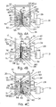
- thermocycler subassembly 12 further includes four heaters: a first heater 25, a second heater 26, a third heater 27, and a fourth heater 28, as shown in FIG. 3 and as shown diagrammatically in FIGS. 1A-1E .
- Each heater 25, 26, 27, 28 includes a head 54 having a first surface 56 facing the one or more vessels 18, as is discussed below, and an opposite surface 58.
- each head 54 is generally rectangular in shape, as shown in FIG. 3 . However, it is within the scope of this disclosure to include a head having any suitable shape for thermally contacting vessels 18.
- Each heater 25, 26, 27, 28 further includes a heater element 60 coupled to the contact surface 56 of each heater 25, 26, 27, 28.
- Heater element 60 illustratively may be a thin-film metal heater or one or more circuit-board based heaters, or a combination of the two.
- Metallic (e.g. copper) wires or traces may be etched into the circuit-board based heaters.
- Each heater head 56 is illustratively a metal plate so that heat produced by heater elements 60 may be uniformly dispersed or distributed. Each head or metal plate 56, however, is an optional component of the heaters 25, 26, 27, 28.
- Circuit-board based heater elements provide heating by controlling the voltage across the metallic traces and provide temperature sensing by measuring the resistance of the metallic traces.
- a microprocessor can be used to read the calibrated temperature of the circuit-board and control the voltage to achieve the desired temperature. It is also within the scope of this disclosure to include an outer un-etched copper layer of each heater element 60 to increase temperature uniformity. Thick metal heaters and Peltier devices are also an option if the device need not be small.
- Optional active heating can be performed at the higher temperature zone(s) by applying heat purges, or the like, prior to or during sample contact.
- Optional active cooling could be used at the lower temperature zone(s) by use of heat sinks 52 or the like, which are to be in contact with the heating elements (shown in FIGS. 1D and 1E ) for appropriate durations of time, as is discussed below.
- each of the first and second heaters 25, 26 is rigidly coupled to first wall 48 of mounting support 32 by a shaft 33.
- Each shaft 33 is rigidly coupled to first wall 48 so that first and second heaters 25, 26 remain stationary throughout the temperature cycling process, as is described below.
- Each of the second and third heaters 27, 28 are movably coupled to second wall 50 of mounting support 32 by a shaft or linear bearing 34.
- each shaft 34 is rigidly coupled to respective heaters 27, 28 so that heaters 27, 28 are urged to move with each respective shaft 34 relative to wall 50.
- second and third heaters 26, 27 create a first, upper temperature zone 66 and first and fourth heaters 25, 28 create a second, lower temperature zone 68.
- the upper zone 66 is provided for denaturation of the sample 16 while the lower zone 68 is provided for primer annealing and extension.
- the heaters of each zone 66, 68 are programmed to maintain a certain predefined temperature for the heating and cooling of mixture 16 within each vessel 18. As such, zone 66 (including second and third heaters 26, 27) is maintained at a different temperature than zone 68 (including first and fourth heaters 25, 28).
- the upper and lower zones 66, 68 of heaters are diagrammatically shown in FIGS. 1A-1E , for example, and are discussed in greater detail below.
- thermocycling subassembly 12 having additional temperature zones (and thus more heaters) than upper and lower zones 66, 68 described herein.
- third and fourth temperature zones 70, 72 are illustratively shown in FIG. 1A .
- Thermocycler subassembly 12 further includes a first stepper motor 29 and a second stepper motor 31, as shown in FIG. 3 .
- First stepper motor 29 is coupled to and controls third heater 27 positioned in the first, upper zone 66.
- Second stepper motor 31 is coupled to and controls fourth heater 28 positioned in the second, lower zone 68.
- Each stepper motor 29, 31 is provided to move the respective heaters 27, 28 in a linear path along an axis lying along the length of shafts 34.
- stepper motors 29, 31 are shown, it is within the scope of this disclosure to include any suitable type of electromechanical mover or actuator such as servo motors, geared motors, solenoids, piezo-electric devices, etc., for example.
- FIG. 1A diagrammatically illustrates a single soft-sided reaction vessel 18 sandwiched between heaters 25, 26, 27, 28 for use with system 10, and specifically with subassembly 12, of the present disclosure.
- the heaters create two or more temperature zones: first, upper zone 66 and second, lower zone 68.
- Each of the third and fourth heaters 27, 28 is movable between an opened and a closed position because of respective stepper motors 29, 31.
- all sets of heaters are illustratively in an open position for ease in loading vessels 18 therein. As described below and shown in FIGS.
- FIG. 1B illustrates an exemplary two-temperature cycling system in which the third heater 27, within upper temperature zone 66, is in the closed position.
- the portion of vessel 18 within zone 66 has been pressed together to squeeze substantially all of reaction mixture 16 into the portion of vessel 18 within zone 68 (where heater 28 is in the opened position). Therefore, the reaction mixture 16 is in full thermal contact with first and fourth heaters 25, 28 within zone 68 to be heated and/or cooled to the temperature at which first and fourth heaters 25, 28 have been set.
- reaction mixture 16 has been squeezed from zone 66 into zone 68, little, if any, reaction mixture 16 remains at the temperature of zone 66.
- thermal cycling is accomplished by repeating these steps. It is within the scope of this disclosure for approximately 90% or more of the reaction mixture 16 to be transferred between upper and lower temperature zones 66, 68. However, it is within the scope of this disclosure for subassembly 12 to achieve other suitable amounts of mass transfers of mixture 16 during the thermal cycling process. For a two-temperature cycling system, as that shown in FIGS. 1B-1E , the volume of reaction mixture 16 to be placed within each vessel 18 is approximately less than half the maximum volume of the reaction vessel body 19 at any time so that all or substantially all of reaction mixture 16 can be moved between the two temperature zones 66, 68.
- FIGS. 1D and 1E illustrate the use of optional heat sinks 52 to aid with the active cooling of the heaters 25, 28 in the lower temperature zone 68.
- heat sinks 52 are provided for use with heaters 25, 28 of the lower temperature zone 68 for active cooling of heaters 25, 28 during the denaturation phase of the PCR process, as shown in FIG. 1E .
- heat sinks 52 are used for active cooling of heaters 25, 28 during the annealing/extension phase (not shown), or are used continuously by being affixed directly to heaters 25, 28 (not shown).
- heat sinks 52 are aluminum or copper. However, it is within the scope of this disclosure to include other heat sinks made of other suitable materials.
- the lower temperature zone 68 is actively cooled by bringing heat sinks 52 into contact with the back-side or surface 58 of heaters 25, 28.
- the top portions of heaters 25, 28 in the lower temperature zone 68 may have a higher temperature than the remaining portions due to proximity to the higher temperature zone 66 and due to contact with the lower end of the heated fluid sample 16 through the vessel material. Unevenness in temperature along the length of heaters 25, 28 can lead to inefficient and uneven cooling of the sample 16 when the sample 16 is transferred into the lower temperature zone 68 for annealing/extension.
- heat sinks 52 When heat sinks 52 are used during the denaturation phase, they generally circumvent this problem by preventing the occurrence of non-uniform temperature in the lower temperature zone 68.
- heat sinks 52 When heat sinks 52 are used during the annealing/extension phase, they aid in regaining temperature uniformity in the lower temperature zone 68 and allow for a more rapid cool down of the denatured sample when it is transferred into the lower temperature zone 68. When heat sinks 52 are affixed to heaters 25, 28, they help maintain temperature uniformity of the heaters, and allow for rapid cool down of the denatured sample. By selecting the appropriate thermal mass for the affixed heat sinks 52, it is also possible to minimize power consumption by heaters 25, 28.
- subassembly 12 features an active area between the heaters 110 mm wide and 50 mm high. This is large enough to accommodate twelve reaction vessels 18 (such as array 20) of 100 ⁇ l, or 9 mm of spacing. However, it is within the scope of this disclosure to include a device having another suitably sized active area for vessels 18.
- FIG. 3 illustrates an exemplary subassembly 12 of the system 10 of the present disclosure.
- the parallel array or row 20 of reaction vessels 18 is shown and positioned between first and second heaters 25, 26 and third and fourth heaters 27, 28.
- second and third heaters 26, 27 are maintained at a first temperature high enough to denature double-stranded DNA, typically 90 to 96 degrees Celsius.
- First and fourth heaters 25, 28 are maintained at a second temperature, between 50 and 72 degrees Celsius, to allow annealing of probe, and extension by a thermostable DNA polymerase.
- both of these temperatures to be predetermined, or to be dynamically determined through fluorescence feedback if fluorescence monitoring is performed in real-time using dye systems that discriminate double strand from single strand DNA. See U.S. Patent No. 6,174,670 , for example.
- the mobile or movable third and fourth heaters 27, 28 are each mounted on respective shaft 34.
- the stepper motor 29 acts to adjust the distance between the third heater 27 and the stationary second heater 26 by propelling the mobile third heater 27 with the shaft 34 in a direction toward stationary heater 26.
- the distance between the heaters in the lower zone 68 (defined by first, stationary heater 25 and fourth, movable heater 28) is controlled by second stepper motor 31.
- Means to control the opening and closing of temperature zones 66, 68 do not have to be limited to stepper motors.
- the use of pneumatic bladders, as shown in FIG. 9 to move the third and fourth heaters 27, 28 is also a viable method.
- each heater 25, 26, 27, 28 is elongated and shaped for contacting the entire row 20 of reaction vessels 18.
- each subsection may be controlled by a separate means for moving.
- a strip or row 20 of reaction vessels 18 is loaded into the active area of subassembly 12, as shown in FIG. 4A , such that row 20 extends between the upper and lower pairs of heaters 29.
- the fourth heater 28 is moved to the closed position toward first, stationary heater 25, as shown in FIG. 4B . Moving heater 28 to the closed position causes heater 28 and heater 25 to impinge on the outer walls of the reaction vessels 18 positioned therebetween, thus squeezing substantially all of the reaction mixture 16 to the upper portion of the respective reaction vessel 18.
- the width of a vessel receptacle gap 35 between second heater 26 and third heater 27, in the opened position is large enough to allow the mixture 16 to flow into the upper half of the reaction vessel body 19 while still maintaining direct contact with the outer walls of the reaction vessel 18.
- the width of a vessel receptacle gap 37 between heaters 25 and 28, in the closed position has been opened by moving fourth heater 28 to the opened position in a direction away from first heater 25 while the receptacle gap 35 between heaters 26 and 27 is closed by generally simultaneously moving third heater 27 to the closed position toward second heater 25.
- thermocycling subassembly 12 shown in FIGS. 3 and 4A - 4C uses the first and fourth heaters 25, 28 positioned within lower zone 68 as the annealing site
- the upper heaters 26, 27 may be used to anneal and the lower heaters 25, 28 may be used to denature the DNA within the reaction mixture 16.
- three sets of heaters could produce typical three-temperature PCR profiles with different temperatures used for denaturation, annealing, and extension.
- An arrangement where the temperature zones are arranged horizontally rather than standing vertically is also envisioned.
- One way to accomplish rapid uniform heating and cooling of the reaction mixture 16 is to maintain a small distance between heaters 25 and 28 and between heaters 26 and 27 (or, vessel receptacle gap 35) in the active temperature zone.
- rapid temperature uniformity of the reaction mixture 16 can be achieved by agitation of the system 10.
- a vessel receptacle gap 35 of about 0.1 mm to about 2 mm is preferred, with 0.25 to 1 mm being the most preferred, for the active temperature zone when respective heaters are in the opened position for effective heating or cooling of the reaction mixture.
- a vessel receptacle gap 37 is brought as close as possible to the thickness of the fully collapsed sample vessel, illustratively approximately 0.1 to 0.15 mm.
- the speed of closing and opening of the heaters 29 within each respective zone is relatively fast. Again, in the case of two-temperature PCR systems, a closing and opening speed of 5 mm/s to 0.01 mm/s is preferred, with about 1 mm/s being the most preferred. However, it is within the scope of this disclosure for heaters 27, 28 to open and close at other suitable speeds. Further, it is understood that in some applications, slower temperature transitions may be preferred, with concomitant slower closing and opening speeds.
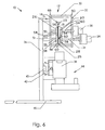
- FIGS. 5 and 6 show the integration of the thermocycling subassembly 12 into the real-time PCR detection system 10.
- thermocycling subassembly 12 is mounted on support 36 coupled to base 46.
- Fluorimeter subassembly 38 is mounted below the thermocycling subassembly 12.
- the fluorimeter subassembly 38 can be moved along a fluorimeter linear bearing 40 by a fluorimeter drive shaft 42.
- a stepper motor 44 is provided and is computer controlled to turn the fluorimeter drive shaft 42 to move the fluorimeter subassembly 38.
- FIG. 6 shows the cross section of the composite apparatus.
- the fluorimeter subassembly 38 can measure the fluorescence of the reaction mixture 16 within one of the reaction vessels 18. Moving the fluorimeter subassembly 38, as described above, allows monitoring of the individual reaction vessels 18 in a row or strip 20.
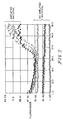
- FIG. 7 illustrates an example of PCR in which a DNA fragment was amplified using the real-time system described in FIGS. 5 and 6 .
- a 110 base pair fragment of the human beta-globin gene was amplified using DNA primers 5'ACACAACTGTGTTCACTAGC (SEQ ID NO. 1) and 5' CAACTTCATCCACGTTCACC (SEQ ID NO. 2) at 0.5 ⁇ M each, 1X SYBR Green I dye (Molecular Probes, Eugene OR, 1:30,000 dilution), 200pM dNTPs, 0.04U/ ⁇ l Taq polymerase with TaqStart Antibody (Roche Molecular Biochemicals, IN), and PCR buffer (Idaho Technology, UT).
- reaction mixtures 16 were placed in reaction vessels 18 and were temperature-cycled for 50 cycles with the following temperature profiles: 95°C, 4 seconds, 60°C, 2 seconds.
- FIG. 7 amplification of material was confirmed in eight reaction mixtures indicated by the increase in fluorescence after 37 cycles.
- the identity of the amplified material was confirmed as the beta-globin fragment by comparing its melting temperature with that of a reference material using the LightCycler system (Roche Molecular Biochemicals).
- the PCR reagents could be lyophilized in the reaction vessel and reconstituted by adding sample dissolved in water.
- Apparatus 110 is similar to apparatus 10 and, therefore, like reference numbers have been used to identify like components. Apparatus 110 also performs the same functions as apparatus 10 such as temperature cycling and detection and analysis of a reaction mixture. Apparatus 110 performs these functions through the use of a thermocycling subassembly 112 and a fluorimeter subassembly 114.
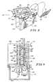
- One difference between apparatus 10 and apparatus 110 is that the movable heaters 27, 28 of apparatus 110 are operated by two sets of pneumatic bladders 129, 131. Although illustrative pneumatic bladders are disclosed, it is within the scope of this disclosure to move heaters 27, 28 through the use of any suitable pressure-based actuator such as hydraulics, spring arrays, etc., for example.
- the first, upper set 129 of bladders includes upper bladders 144, 146 coupled to movable heater 27 and the second, lower set 131 of bladders includes lower bladders 148, 150 coupled to movable heater 28.
- Bladders 144, 146, 148, 150 are each illustratively manufactured by heat-sealing a polyethylene/polypropylene laminate film onto a pneumatic fitting 128. The seals are arranged such that rounded, rectangular areas are created and positioned adjacent the heaters.
- each bladder 144, 146, 148, 150 (and each respective heater 25, 26, 27, 28 coupled thereto) generally runs the length of apparatus 110 so that each bladder 144, 146, 148, 150 affects all vessels 18 within the array 20 of vessels 18.
- each bladder 144, 146, 148, 150 is illustratively coupled to two pneumatic fittings 128, although only one fitting 128 is shown in cross-section in Fig. 9 .
- Apparatus 110 may include a rigid mechanical support 126 coupled to each set 129, 131 of bladders and an insulator 133 coupled to each support 126.
- mechanical support 126 is made of a metal or carbon fiber composite strips, however, it is within the scope of this disclosure for support 126 to be made of any suitable material.
- one insulator 133 is coupled to heater 27 and another insulator 133 is coupled to heater 28.
- Each insulator 133 is made of an insulating material so that the temperature of each respective heater 27, 28 may be more consistently maintained.
- each movable heater 27, 28 is coupled to two bladders.
- heater 27 is coupled to the first, upper set 129 of bladders 144, 146 and heater 28 is coupled to the second, lower set 131 of bladders 148, 150.
- the use of two bladders for each movable heater 27, 28 allows for active mixing of the samples 16 within each of the upper and lower heat zones 66, 68. Agitation of the samples 16 is accomplished by cyclically pressurizing bladders 144 and 146 (of upper set 129) within upper zone 66, for example, or by cyclically pressurizing bladders 148 and 150 (of lower set 131) within lower zone 68.
- Subminiature valves under control of a microprocessor 162 (shown diagrammatically in Fig. 9 ) may be used to switch the high pressure between the two heat zones 66, 68 thus forcing the sample 16 back and forth between the upper and lower temperature zones 66, 68.
- all pneumatic bladders 144, 146, 148, 150 are controlled by microprocessor 160.
- a separate microprocessor is used to control temperature sensing, the heating of the heater elements 60, etc.
- apparatus 110 further includes a sealing mechanism 142 driven by another bladder 152.
- Sealing mechanism 142 includes a spring-retracted seal bar 156 coupled to bladder 152.
- bladder 152 is inflated to actuate spring-retracted seal bar 156 to press seal bar 156 into contact with the array 20 of vessels 18 and between a mating surface 158 of seal bar 156 and an opposite surface 160 of apparatus 110.
- Mating surface 158 of seal bar 156 is illustratively fitted with a nichrome wire (not shown), which can be heated by passing current therethrough. The wire is heated for enough time to melt an inner layer of the reaction vessel body 19, fusing it together and locking the sample 16 into the receptacle.
- sealing mechanism 142 is provided integrally in apparatus 110, it is understood that sealing mechanism 142 is optional, and that the vessels 18 may be sealed by any number of ways, as is known in the art.
- a controller board (not shown) is also provided and includes a heater board retraction spring, MAC valves, and receptacles for fittings 128.
- Apparatus 110 is illustratively battery operated and includes an internal pneumatic system, described above, including first and second sets 129, 131 bladders 144, 146 and 148, 150.
- first set 129 of bladders 144, 146 acts as a first mover or actuator of the system and second set 131 of bladders 144, 146 acts as a second mover or actuator of the system.
- a disposable twenty-five gram carbon dioxide cylinder 132 is illustratively used to drive the pneumatic system. While FIGS. 8 and 9 illustrate a portable, battery operated unit, it is understood that apparatus 110 may be configured to run off of a standard electrical source. Furthermore, while a carbon dioxide cylinder 132 is illustrated, it is understood that other compressed fluid sources may be used within the scope of this disclosure.
- apparatus 110 includes a transport box 111 having a body 116 and a lid 118 illustratively coupled to the body 116 by hinges (not shown) so that lid 118 pivots between an opened position, as shown, and a closed position.
- box 111 is made of sturdy anodized aluminum, however, it is within the scope of this disclosure to include a transport box made of other suitable materials.
- Latches 120 are coupled to a front surface 122 of body 116 so that lid 118 may be locked in the closed position and the transport box may be easily carried.
- Lid 118 illustratively includes a 386 DOS computer 124, however, any suitable computer or microprocessor may be used.
- a PC interface 130 is provided so that computer 124 may be connected to a user's PC to download information gathered from the apparatus 110 to the PC.
- An interface 134 illustratively a soft key interface, is provided including keys for inputting information and variables such as temperatures, cycle times, etc.
- a 2x20 mm character display 136 is also provided. Display 136 may be an LED, LCD, or other such display, for example.
- body 116 of box 111 includes a top surface 138 having a slot 140 formed therein for receiving array 20 of vessels 18. It is understood that other microprocessors may be used within the scope of this invention. It is further understood that the microprocessor need not be provided as an integral component of the apparatus 110, and, depending upon the application, that a microprocessor may not be needed at all.
- Illustrative automatic calling software may be provided to analyze the samples by a multi-test analysis method described in U.S. Patent Application Serial Nos. 10/074,178 and 10/117,948 , ( US 2003-0165867A and US 2003-015748A ) with the following modifications and additions.
- Multiple points for example, 10, 20, 30, or 50 points
- Data points from portions of the sample vessel 18 that are close to seal 22 are preferably not used due to edge effects in fluorescence.
- the software Prior to taking the median, the software also compares the individual fluorescence values with data acquired from the cycle preceding the present acquisition, and ignores those values that are significantly different in value. This allows the software to ignore portions of the sample vessel 18 which further generate erroneous fluorescence signal due to the appearance, or drift, of air bubbles and other interfering particles in the reaction. It is understood that other numerical methods besides taking a median value may be sued to reduce the many measurements taken across the bottom to a single fluorescence value for each sample. These include fourier transformation, averaging, fitting to known functions, and stored standards. Finally, in an illustrated embodiment, the classification of a sample (i.e.
- apparatus 110 further includes gas chamber 132 for providing compressed gas to the first and second sets 129, 131 of pneumatic bladders 144, 146, 148, 150.
- gas chamber 132 for providing compressed gas to the first and second sets 129, 131 of pneumatic bladders 144, 146, 148, 150.
- cylinder 132 is positioned near slot 140 so that a portion of chamber 132 protrudes above top surface 138 of body 116.
- Chamber 132 is removable from body 116 of transport box 111 so that a user may refill the chamber 132 as needed.
- chamber 132 is illustratively cylindrical in shape, it is within the scope of this disclosure to include a gas chamber having any suitable shape for feeding compressed air to bladders 129, 131.
- apparatus 110 includes thermocycling subassembly 112 and fluorimeter subassembly 114, each positioned within body 116 of transport box 111.
- Computer 124 of apparatus 110 may control certain functions of both subassemblies 112, 114. It is also within the scope of this disclosure, however, to include other computers or microprocessors for separately controlling the subassemblies 112, 114.
- thermocycling subassembly 112 includes heaters 25, 26, 27, 28 to create upper and lower temperature zones 66, 68. Further, heaters 25 and 26 are stationary heaters and heaters 27 and 28 are movable heaters. As mentioned before, first, upper set 129 of pneumatic bladders 144, 146 is coupled to heater 27 and second, lower set 131 of pneumatic bladders 148, 150 is coupled to heater 28. Although it is shown that two bladders are coupled to each heater, it is within the scope of this disclosure to couple a heater to any suitable number of pneumatic bladders. Each bladder 144, 146, 148, 150 is coupled to the carbon dioxide chamber 132.
- Microprocessor 160 controls the inflation and deflation of each set 129, 131 of bladders 144, 146, 148, 150 as is required for the temperature cycling process described above with respect to apparatus 10.
- Pneumatic bladders 144, 146, 148, 150 provide high, uniform actuation forces on respective heaters 27, 28.
- illustrative bladders 144, 146, 148, 150 are relatively light and occupy little space allowing for apparatus 110 to be small, compact, and portable.
- Subassembly 112 also includes an eleven-valve manifold coupled to the bladders 144, 146, 148, 150 to regulate the carbon dioxide gas into and out of each bladder 144, 146, 148, 150.
- an eleven-valve manifold is disclosed herein, it is within the scope of this disclosure to include a manifold having another suitable number of valves to operate bladders 144, 146, 148, 150.
- the carbon dioxide gas within gas chamber 132 is regulated to 30 psi and is switched through the manifold to minimize electrical losses from the valves.
- First set 129 of pneumatic bladders 144, 146 forces movable heater 27 toward stationary heater 25 while second set 131 of pneumatic bladders 148, 150 forces movable heater 28 toward stationary heater 26 in order to force samples 16 within each vessel 18 between lower and upper temperature zones 66, 68.
- the illustrative sets 129, 130 of bladders 144, 146 and 148, 150 are able to produce a rocking motion on respective movable heaters 27 and 28 to allow mechanical mixing of the samples 16 within each temperature zone 66, 68. Mixing the samples 16 by the rocking motion of the heaters 27, 28 increases temperature uniformity within each sample 16 and aids in positioning each sample 16 for optimal fluorescence measurement at the bottom of each respective vessel body 19.
- Subassembly 112 further includes a sealing mechanism 142, shown in FIG. 9 and described above, positioned above heaters 26, 27.
- Array 20 of vessels 18 are inserted into slot 140 of body 116 and between mating surface 158 of seal bar 156 and surface 160.
- Seal bar 156 is urged to move toward surface 160 by pneumatic bladder 152 to lock and seal the array 20 of vessels 18 therebetween, as described above.
- seal bar 156 operates to heat seal an upper portion of the vessel body 19 of each vessel 18 together to form a seal.
- seal bar 156 it is within the scope of this disclosure for seal bar 156 to simply clamp or secure array 20 of vessels 18 between stationary heaters 25, 26 and movable heaters 27, 28.
Abstract
Description
- The present invention relates to a thermal cycling system and method that facilitates rapid, uniform temperature cycling of samples. Illustratively, the invention is designed to perform DNA amplification and detection of amplified products within a reaction vessel.
- Amplification of DNA by polymerase chain reaction (PCR) requires reaction mixtures be subjected to repeated rounds of heating and cooling. All commercially available instruments for PCR operate by changing the temperature of the environment of a reaction vessel, either by heating and cooling the environment, or by robotically moving the samples between environments. The most common instruments for temperature cycling use a metal block to heat and cool reaction mixtures. Thermal mass of the metal block is typically large, meaning temperature transitions are relatively slow and require a large amount of energy to cycle the temperature. The reaction mixture is typically held in microcentrifuge tubes or microtiter plates consisting of rigid injection molded plastic vessels. These vessels need to be in uniform contact with the metal block for efficient heat transfer to occur. Maintaining temperature uniformity across a large heat block has also been a challenge.
- Novel techniques have been devised to overcome the challenges of using instruments with metal blocks for heating and cooling samples. Airflow can be used to thermocycle samples in plastic reaction tubes (
U.S. Pat. 5,187,084 ), as well as in capillary reaction tubes (Wittwer, et al, "Minimizing the time required for DNA amplification by efficient heat transfer to small samples", Anal Biochem 1990, 186:328-331 andU.S. Pat. No. 5,455,175 ). Capillary tubes provide a higher surface area to volume ratio than other vessels. Using air as the thermal medium allows rapid and uniform temperature transitions when small sample volumes are used. - Further, the capillary tubes themselves can be physically moved back and forth across different temperature zones (
Corbett, et al., U.S. Pat. No 5,270,183 , Kopp et al., 1998, andHaff et al., U.S. Pat No. 5,827,480 ), or the sample can be moved within a stationary capillary (Hunicke-Smith, U.S. Pat. No. 5,985,651 andHaff, et al., U.S. Pat. No. 6,033,880 ). With the latter technique, contamination from sample to sample is a potential problem because different samples are sequentially passed through the winding capillary tube. Additionally, tracking the physical position of the sample is technically challenging. - The use of sample vessels formed in thin plastic sheets has also been described. Schober et al. describe methods for forming shallow concave wells on plastic sheets in an array format similar to a microtiter plate (Schober et al, "Multichannel PCR and serial transfer machine as a future tool in evolutionary biotechnology", Biotechniques 1995, 18:652-661). After samples are placed in the pre-formed well, a second sheet is placed over the top, and the vessel is heat-sealed. The accompanying thermal cycling apparatus physically moves a tray of samples between different temperature zones (Schober et al. and
Bigen et al., U.S. Pat. No. 5,430,957 ). The use of multiple heating blocks for the temperature zones makes this machine large and cumbersome. - Another system using reaction chambers formed between two thin sheets of plastic has been described where the vessel has multiple individual compartments containing various reaction reagents (Findlay et al, "Automated closed-vessel system for in vitro diagnostics based on polymerase chain reaction", Clin Chem 1993, 39:1927-1933, and
Schnipelsky, et al., U.S. Pat. No. 5,229,297 ). The compartments are connected through small channels that are sealed at the beginning of the process. One apparatus has a moving roller that squeezes the vessel while traveling from one end of the vessel to another. The pressure from the roller breaks the seal of the channels and brings the sample into contact with reagents. Temperature is controlled by a heater attached to the roller mechanism (DeVaney, Jr., et al., U.S. Pat. No. 5,089,233 ). A second apparatus uses pistons to apply pressure to the compartments and move the fluid (DeVaney, Jr., U.S. Pat. No. 5,098,660 ). The temperature of one of the pistons can be altered while in contact with the vessel to accomplish thermal cycling. In both of these examples, the temperature of a single heating element is being cycled. Changing the temperature of the heating element is a relatively slow process. - Another system uses a planar plastic envelope (
Corless et al. W09809728A1 -
WO 02/057798 A2 (publication date:25.07.02 - Real-time monitoring of PCR is enabled using reaction chemistries that produce fluorescence as product accumulates in combination with instruments capable of monitoring the fluorescence. Real-time systems greatly reduce the amount of sample transfer required between amplification reaction and observation of results. Additionally, in some systems, quantitative data can also be collected.
- A number of commercially available real-time PCR instruments exist that couple a thermal cycling device with a fluorescence monitoring system. Of these real-time instruments, thermal cycling in the Perkin-Elmer 5700 and 7700 and the Bio-Rad iCycler instruments are based on metal heat blocks. The Roche LightCycler, the Idaho Technology Ruggedized Advanced Pathogen Identification system (or R.A.P.I.D.) and the Corbett RotoGene all use air to thermocycle the reactions. The Cepheid SmartCycler uses ceramic heater plates that directly contact the sample vessel.
- The present invention provides a temperature cycling apparatus and a method for thermal cycling a fluid sample as defined in claims 1 and 11.
- In an illustrated embodiment, a reaction mixture is placed in a soft-sided flexible vessel that is in thermal contact with a plurality of temperature zones comprising a plurality of movable heating or heater elements. When pressure is applied to the vessel by closing all except one set of the heater elements, the reaction mixture inside the vessel moves to the heater element that is left open. The reaction mixture can be moved between different portions of the vessel and can be exposed to different temperature zones by selective opening and closing of the heater elements. Temperature change of the reaction mixture occurs rapidly and almost instantaneously. The vessel can be of any shape, illustratively elongated, and made of a flexible material, such as thin plastic film, foil, or soft composite material, provided that the material can hold the reaction mixture and can withstand temperature cycling. Exemplary plastic films include, but are not limited to, polyester, polyethylene terephthalate (PET), polycarbonate, polypropylene, polymethylmethacrylate, and alloys thereof and can be made by any process as known in the art including coextrusion, plasma deposition, and lamination. Plastics with aluminum lamination, or the like, may also be used.
- The heater elements can be made of, for example, thin-film metal heaters, ceramic semiconductor elements, peltier devices, or circuit boards etched with metallic (e.g. copper) wires, or a combination of the above, with optional metal plates for uniform heat dispersion. Thick metal heaters are also an option if the device need not be small. Other heaters known in the art may be used.
- The heater elements are held at, or around, a set of characteristic temperatures for a particular chemical process, such as PCR. When the chemical process is PCR, at least two temperature zones are required: one at a temperature that is effective for denaturation of the nucleic acid sample, the other at a temperature that allows primer annealing and extension. As illustrated, reaction vessels are inserted in the apparatus when the heater elements for both temperature zones are in an open position. To temperature cycle for PCR, the heater element of one temperature zone is brought to the closed position, pushing the reaction mixture toward the open temperature zone at the other end of the vessel. In the open temperature zone, the heater element is in thermal contact with the vessel wall. Following an appropriate incubation time, the element of the zone heater is brought to the closed position, while the element of the other zone is opened. This action forces the reaction mixture to move to the other temperature zone. This process of opening and closing temperature zones is repeated as many times as required for nucleic acid amplification. It is understood that additional heater elements may be used for processes requiring more than two temperatures. For example, PCR reactions often use a denaturation temperature, an annealing temperature, and an extension temperature.
- The foregoing and many other aspects of the present invention will become more apparent when the following detailed description of the preferred embodiments is read in conjunction with the various figures.
-
-
FIGS. 1A to IE are cross-sectional diagrammatic views of a comparative example of a reaction vessel containing a reaction mixture positioned between heater elements of the present disclosure. -
FIG. 1A is a diagrammatic view of the vessel positioned between at least three pairs of heater elements showing each element spaced-apart from the vessel. -
FIG. 1B is a diagrammatic view similar toFIG. 1A of the vessel positioned between two pairs of heater elements and showing a top pair of the elements in a closed position and a bottom pair of the elements in an opened position so that generally all of the reaction mixture is positioned between and heated by the bottom pair of elements. -
FIG. 1C is a diagrammatic view similar toFIGS. 1A and IB showing the bottom pair of elements in the closed position and the top pair of elements in the opened position so that generally all of the reaction mixture is positioned between and heated by the top pair of elements at a different temperature than the bottom pair of elements. -
FIG. 1D is a diagrammatic view similar toFIG. 1B showing the bottom pair of elements in the opened position and the top pair of elements in the closed position and further showing a heat sink adjacent but spaced-apart from each of the bottom pair of elements. -
FIG. 1E is a diagrammatic view similar toFIG. 1D showing the bottom pair of elements in the closed position and the top pair of elements in the opened position and further showing each of the heat sinks having engaged the respective element to cool the bottom pair of elements. -
FIG. 2A is a perspective view of the reaction vessel showing a receptacle coupled to a flexible body of the vessel. -
FIG. 2B is a perspective view of an array of reaction vessels coupled to each other to form a single row. -
FIG. 3 is a perspective view of an illustrative thermocycling subassembly for use with a real-time PCR apparatus of the present disclosure (shown inFIGS. 5 and6 ) showing a first and a second stepper motor of the subassembly, top and bottom pairs of heater elements, and the row of reaction vessels positioned between the pairs of elements. -
FIGS. 4A to 4C are side views of the thermocycling subassembly shown inFIG. 3 showing thermocycling of the reaction mixture contained within the vessels. -
FIG. 4A is a side view thermocycling subassembly showing the top and bottom pairs of elements in the opened position prior to heating the reaction mixture within the vessels. -
FIG. 4B is a side view of the thermocycling subassembly showing the bottom pair of elements in the closed position so that the reaction mixture is in thermal contact with the top pair of elements. -
FIG. 4C is a side view of the thermocycling subassembly showing the top pair of elements in the closed position and the bottom pair of elements in the opened position so that so that the reaction mixture is in thermal contact with the bottom of elements. -
FIG. 5 is a perspective view of the thermocycling subassembly integrated into the real-time PCR apparatus including the thermocycling subassembly and a fluorimeter subassembly. -
FIG. 6 is a side view of the real-time PCR apparatus shown inFIG. 5 . -
FIG. 7 is a graph showing the results of real-time monitoring of PCR in which DNA amplification is detected by the increase in relative fluorescence in the annealing temperature zone. (Δ, O, ●, □ are negative controls; ∇,, ◆, + are positive samples)
-
FIG. 8 is a perspective view of an alternative real-time PCR apparatus showing a body of the apparatus including a slot for placing sample vessels therein and a pressurized gas chamber adjacent the slot, and showing the apparatus further including a lid hinged to the body and including a computer having a PC interface and display monitor. -
FIG. 9 is a part schematic, part diagrammatic sectional view of the components located within the body of the PCR apparatus shown inFIG. 8 showing an alternative thermocycling subassembly having pneumatic bladders and the fluorimeter subassembly positioned below the thermocycling subassembly. - A real-time thermal cycling apparatus or
system 10 is provided, as shown inFIGS. 5 and6 , for use in temperature controlled processes such as amplification of DNA by PCR or cycle-sequencing, for example, and optionally for use in detecting and analyzing a reaction by monitoring fluorescence. Illustratively,system 10 is used as a biological agent identification system for specifically identifying organisms by their unique genetic makeup.System 10 includes athermocycling subassembly 12 and afluorimeter subassembly 38. In general,thermocycling subassembly 12 subjects a reaction mixture or sample 16 (shown as a comparative example inFIGS. 1A-1E ) including a nucleic acid sample to temperature cycling, or repeated rounds of heating and cooling, illustratively, for denaturation of the nucleic acid sample and for primer annealing and elongation. Thesamples 16 are sealed inside flexibleplastic film vessels 18 and actuators ofsubassembly 12 squeeze thevessels 18 back and forth so thatsamples 16 are moved between two or more temperature zones.Subassembly 38 detects and analyzes the reaction in real-time by monitoring cycle dependent and/or temperature-dependent fluorescence.System 10 further includes a vertical support structure shown asmechanical breadboard 36 and a base 46 coupled to supportstructure 36. As is shown inFIG. 5 , eachsubassembly structure 36. Each of thesubassemblies - As mentioned above,
reaction mixture 16 includes a nucleic acid sample, for example, and is contained within a single, soft-sided reaction vessel 18, as shown inFIG. 2A .Vessel 18 is used insystem 10 and includes areaction vessel body 19 and areceptacle 24 for receiving thenucleic acid sample 16. Thereaction vessel body 19 is formed between two planar faces of plastic sheeting sealed together to form sealed sides 22.Individual vessels 18, therefore are separated from neighboringvessels 18 by sealedsides 22. Liquid can be loaded into thereceptacle 24 and moved to thereaction vessel body 19, that is initially squeezed flat, by means such as gravity or a vacuum applied to the outer walls of thevessel 18. Oncesamples 16 are loaded into thereaction vessel body 19, thevessel 18 can be sealed to createseal 21 by heat-sealing, clamping, or through the use of adhesives, for example. - Alternatively, the
receptacle 24 can be fitted with a plastic fitment (not shown) manufactured from polypropylene, for example. Eachvessel body 19 may be tapered at the top to a point (not shown) with the plastic fitment coupled thereto so that through use of either a pipette or a syringe-like plug,samples 16 could be forced into thereaction vessel body 19. Each plastic fitment attaches to the top of arespective vessel body 19 and includes an injection port into the respective vessel body. Liquid reagents, therefore, may be injected intobody 19 using a pipette, for example. Excess air may then be squeezed out ofbody 19 prior to loading thevessels 18 into thethermocycling subassembly 12 for heat-sealing and thermal cycling, as is described in greater detail below. - Additionally, an illustrative polypropylene fitting or plastic cap 23 (shown in
FIGS. 2A and 2B ) may be used to provide a secondary closure of thevessels 18. The plastic caps 23 may also be used to seal thevessel body 19 at the fitment, thereby obviating the need to sealbody 19 at sealingarea 21. It is within the scope of this disclosure for such aplastic cap 23 to be threadably attached tovessel body 19, snap-fit onto or withinvessel body 19, and/or melted intobody 19, etc. - In yet another alternative embodiment, a larger plastic fitting or fitment (not shown) may also be used to allow
sample 16 to be freeze-dried inside a plurality of openings in the fitting, for example, twelve openings. A single injection port is connected to several of thereaction vessels 18, and when a prepared DNA sample is inserted into the port, thesample 16 is drawn into thebody 19 of eachvessel 18 automatically by the force of the vacuum. This automatic distribution ofsamples 16 may be used fortesting sample 16 for multiple pathogens or multiple genes from a single source. A syringe plunger is inserted into the top of the fitting and is pressed down automatically at the end of the freeze-drying process, thus sealing the reagent pellet in vacuum. Thebody 19 is then vacuum sealed inside a protective bag for long-term stability. SeeU.S. Provisional Application No. 60/374,730, filed April 23, 2002 PCT/US03/12688 . -
Vessel body 19 is made of a flexible material. Such flexible materials include but are not limited to thin plastic films, foil, or soft composite materials, provided that they can hold thereaction mixture 16, and can withstand repeated exposure to temperatures used in the reaction without deformation, crazing, cracking, or melting. Plastic films of polyester, (PET), polycarbonate, polypropylene, polymethylmethacrylate, and alloys thereof made by coextrusion, plasma deposition, lamination or the like are preferred. Plastics with aluminum lamination, or the like, are also preferred. Further,vessel body 19 has a coefficient of heat transfer approximately in the range of 0.02-20 W/m*degK. Becausevessel body 19 is thin, it does not effectively transfer heat between portions ofvessel body 19 in contact with different heaters at different temperatures, as is discussed below. - If fluorescence monitoring of the reaction is desired, through the use of
subassembly 38, for example, plastic films that are adequately low in absorbance and autofluorescence at the operative wavelengths are preferred. Such material could be found by trying different plastics, different plastisizers and composite ratios, as well as different thickness of the film. For plastics with aluminum or other foil lamination, the portion of thevessel 18 that is to be read by thefluorescence detection device 38 can be left without the foil. In the example of PCR, film laminates composed of polyester (Mylar, Dupont, Wilmington DE) of about 0.0048 inch (0.1219 mm) thick and polypropylene films of 0.001 - 0.003 inch (0.025 - 0.076 mm) thick perform well. Illustratively,vessel body 19 is made of a clear material so that thevessel body 19 is capable of transmitting approximately 80% - 90% of incident light. - To perform simultaneous reactions of multiple samples, the
vessels 18 are illustratively arranged to form an array orrow 20 ofreaction vessels 18, as shown inFIG. 2B . In the illustrated embodiments, thevessels 18 are arranged with 9 mm or 6 mm spacing to mimic the spacing found on standard 96-well or 384-well microtiter plates. However, it is within the scope of this disclosure to include arow 20 ofvessels 18 having other suitable spacing.FIG. 2B illustrates the row orarray 20 ofvessels 18 to includes twelvereaction vessels 18. It is within the scope of this disclosure, however, to include other configurations having other numbers ofvessels 18 for use withsystem 10 of the present disclosure. When used with fluroescence, for example, for real-time monitoring, abottom edge 14 of sealedsides 22 may be blackened to reduce bleed-over of fluroescent light from onesample vessel 18 to the next. - As mentioned above, vessels 18 (or
row 20 of vessels 18) are used withthermocycling subassembly 12, shown inFIGS. 3-5 . Illustratively, as shown inFIG. 3 ,thermocycling subassembly 12 includes a mountingsupport 32 having afirst wall 48 and asecond wall 50 spaced apart fromfirst wall 48 and coupled tofirst wall 48 byspacers 30. Illustratively, there are fourspacers 30 coupled to each of the first andsecond walls support 32. Mountingsupport 32 further includesmounts 51 coupled tofirst wall 48 so that mountingsupport 32 may be coupled to supportstructure 36, as shown inFIG. 6 , for example. - Illustratively,
thermocycler subassembly 12 further includes four heaters: afirst heater 25, asecond heater 26, athird heater 27, and afourth heater 28, as shown inFIG. 3 and as shown diagrammatically inFIGS. 1A-1E . Eachheater head 54 having afirst surface 56 facing the one ormore vessels 18, as is discussed below, and anopposite surface 58. Illustratively, eachhead 54 is generally rectangular in shape, as shown inFIG. 3 . However, it is within the scope of this disclosure to include a head having any suitable shape for thermally contactingvessels 18. - Each
heater heater element 60 coupled to thecontact surface 56 of eachheater Heater element 60 illustratively may be a thin-film metal heater or one or more circuit-board based heaters, or a combination of the two. Metallic (e.g. copper) wires or traces may be etched into the circuit-board based heaters. Eachheater head 56 is illustratively a metal plate so that heat produced byheater elements 60 may be uniformly dispersed or distributed. Each head ormetal plate 56, however, is an optional component of theheaters heater element 60 to increase temperature uniformity. Thick metal heaters and Peltier devices are also an option if the device need not be small. Optional active heating can be performed at the higher temperature zone(s) by applying heat purges, or the like, prior to or during sample contact. Optional active cooling could be used at the lower temperature zone(s) by use ofheat sinks 52 or the like, which are to be in contact with the heating elements (shown inFIGS. 1D and 1E ) for appropriate durations of time, as is discussed below. - As shown in
FIG. 3 , and diagrammatically inFIGS. 1A-1E , each of the first andsecond heaters first wall 48 of mountingsupport 32 by ashaft 33. Eachshaft 33 is rigidly coupled tofirst wall 48 so that first andsecond heaters third heaters second wall 50 of mountingsupport 32 by a shaft orlinear bearing 34. As shown inFIGS. 4A-4C , eachshaft 34 is rigidly coupled torespective heaters heaters respective shaft 34 relative to wall 50. - Further, second and
third heaters upper temperature zone 66 and first andfourth heaters lower temperature zone 68. Illustratively, theupper zone 66 is provided for denaturation of thesample 16 while thelower zone 68 is provided for primer annealing and extension. The heaters of eachzone mixture 16 within eachvessel 18. As such, zone 66 (including second andthird heaters 26, 27) is maintained at a different temperature than zone 68 (including first andfourth heaters 25, 28). The upper andlower zones FIGS. 1A-1E , for example, and are discussed in greater detail below. Further, it is within the scope of this disclosure to include athermocycling subassembly 12 having additional temperature zones (and thus more heaters) than upper andlower zones fourth temperature zones FIG. 1A . -
Thermocycler subassembly 12 further includes afirst stepper motor 29 and asecond stepper motor 31, as shown inFIG. 3 .First stepper motor 29 is coupled to and controlsthird heater 27 positioned in the first,upper zone 66.Second stepper motor 31 is coupled to and controlsfourth heater 28 positioned in the second,lower zone 68. Eachstepper motor respective heaters shafts 34. Althoughstepper motors -
FIG. 1A diagrammatically illustrates a single soft-sided reaction vessel 18 sandwiched betweenheaters system 10, and specifically withsubassembly 12, of the present disclosure. As mentioned above, the heaters create two or more temperature zones: first,upper zone 66 and second,lower zone 68. Each of the third andfourth heaters respective stepper motors FIG. 1A , all sets of heaters are illustratively in an open position for ease inloading vessels 18 therein. As described below and shown inFIGS. 1B-1E , thereaction mixture 16 inside thereaction vessel 18 is incubated in a particular temperature zone when the particular heater within that temperature zone is held in the opened position while all other heaters within other zones are in the closed position.FIG. 1B illustrates an exemplary two-temperature cycling system in which thethird heater 27, withinupper temperature zone 66, is in the closed position. As shown inFIG. 1B , the portion ofvessel 18 withinzone 66 has been pressed together to squeeze substantially all ofreaction mixture 16 into the portion ofvessel 18 within zone 68 (whereheater 28 is in the opened position). Therefore, thereaction mixture 16 is in full thermal contact with first andfourth heaters zone 68 to be heated and/or cooled to the temperature at which first andfourth heaters reaction mixture 16 has been squeezed fromzone 66 intozone 68, little, if any,reaction mixture 16 remains at the temperature ofzone 66. - After an appropriate duration,
heater 27 is moved to the open position so thatzone 66 is opened andheater 28 is moved to the closed position so thatzone 68 is closed, thus moving thereaction mixture 16 into the upper portion ofvessel 18 and into full thermal contact with second andthird heaters upper zone 66, as shown inFIG. 1C . Thermal cycling is accomplished by repeating these steps. It is within the scope of this disclosure for approximately 90% or more of thereaction mixture 16 to be transferred between upper andlower temperature zones subassembly 12 to achieve other suitable amounts of mass transfers ofmixture 16 during the thermal cycling process. For a two-temperature cycling system, as that shown inFIGS. 1B-1E , the volume ofreaction mixture 16 to be placed within eachvessel 18 is approximately less than half the maximum volume of thereaction vessel body 19 at any time so that all or substantially all ofreaction mixture 16 can be moved between the twotemperature zones -
FIGS. 1D and 1E illustrate the use ofoptional heat sinks 52 to aid with the active cooling of theheaters lower temperature zone 68. Illustratively,heat sinks 52 are provided for use withheaters lower temperature zone 68 for active cooling ofheaters FIG. 1E . Alternatively,heat sinks 52 are used for active cooling ofheaters heaters 25, 28 (not shown). Illustratively,heat sinks 52 are aluminum or copper. However, it is within the scope of this disclosure to include other heat sinks made of other suitable materials. Thelower temperature zone 68 is actively cooled by bringingheat sinks 52 into contact with the back-side orsurface 58 ofheaters heaters lower temperature zone 68 may have a higher temperature than the remaining portions due to proximity to thehigher temperature zone 66 and due to contact with the lower end of theheated fluid sample 16 through the vessel material. Unevenness in temperature along the length ofheaters sample 16 when thesample 16 is transferred into thelower temperature zone 68 for annealing/extension. When heat sinks 52 are used during the denaturation phase, they generally circumvent this problem by preventing the occurrence of non-uniform temperature in thelower temperature zone 68. When heat sinks 52 are used during the annealing/extension phase, they aid in regaining temperature uniformity in thelower temperature zone 68 and allow for a more rapid cool down of the denatured sample when it is transferred into thelower temperature zone 68. When heat sinks 52 are affixed toheaters heat sinks 52, it is also possible to minimize power consumption byheaters - Illustratively,
subassembly 12 features an active area between the heaters 110 mm wide and 50 mm high. This is large enough to accommodate twelve reaction vessels 18 (such as array 20) of 100µl, or 9 mm of spacing. However, it is within the scope of this disclosure to include a device having another suitably sized active area forvessels 18. -
FIG. 3 illustrates anexemplary subassembly 12 of thesystem 10 of the present disclosure. The parallel array orrow 20 ofreaction vessels 18 is shown and positioned between first andsecond heaters fourth heaters third heaters fourth heaters U.S. Patent No. 6,174,670 , for example. - As shown in
FIG. 4A , the mobile or movable third andfourth heaters respective shaft 34. Thestepper motor 29 acts to adjust the distance between thethird heater 27 and the stationarysecond heater 26 by propelling the mobilethird heater 27 with theshaft 34 in a direction towardstationary heater 26. In the same manner, the distance between the heaters in the lower zone 68 (defined by first,stationary heater 25 and fourth, movable heater 28) is controlled bysecond stepper motor 31. Means to control the opening and closing oftemperature zones FIG. 9 , to move the third andfourth heaters heaters Fig. 3 , eachheater entire row 20 ofreaction vessels 18. However, it is within the scope of this disclosure to provide themovable heaters individual reaction vessels 18 independently. Each subsection may be controlled by a separate means for moving. - In the operation of the two-temperature
thermal cycling system 10 illustrated, a strip orrow 20 ofreaction vessels 18 is loaded into the active area ofsubassembly 12, as shown inFIG. 4A , such thatrow 20 extends between the upper and lower pairs ofheaters 29. To thermal cycle thereaction mixtures 16, thefourth heater 28 is moved to the closed position toward first,stationary heater 25, as shown inFIG. 4B . Movingheater 28 to the closed position causesheater 28 andheater 25 to impinge on the outer walls of thereaction vessels 18 positioned therebetween, thus squeezing substantially all of thereaction mixture 16 to the upper portion of therespective reaction vessel 18. The width of avessel receptacle gap 35 betweensecond heater 26 andthird heater 27, in the opened position, is large enough to allow themixture 16 to flow into the upper half of thereaction vessel body 19 while still maintaining direct contact with the outer walls of thereaction vessel 18. As shown inFIG. 4C , the width of avessel receptacle gap 37 betweenheaters FIG. 4B ), has been opened by movingfourth heater 28 to the opened position in a direction away fromfirst heater 25 while thereceptacle gap 35 betweenheaters third heater 27 to the closed position towardsecond heater 25. - While the illustrated embodiment of the
thermocycling subassembly 12 shown inFIGS. 3 and4A - 4C uses the first andfourth heaters lower zone 68 as the annealing site, those skilled in the art could envision other arrangements. For example, theupper heaters lower heaters reaction mixture 16. Further, as mentioned above, it is within the scope of this disclosure to include asubassembly 12 having more than two sets or zones of heaters for cycling between more than two temperatures. For example, three sets of heaters could produce typical three-temperature PCR profiles with different temperatures used for denaturation, annealing, and extension. An arrangement where the temperature zones are arranged horizontally rather than standing vertically is also envisioned. - One way to accomplish rapid uniform heating and cooling of the
reaction mixture 16 is to maintain a small distance betweenheaters heaters 26 and 27 (or, vessel receptacle gap 35) in the active temperature zone. However, it is also conceivable that rapid temperature uniformity of thereaction mixture 16 can be achieved by agitation of thesystem 10. Illustratively, for temperature transitions used in two-temperature PCR systems, avessel receptacle gap 35 of about 0.1 mm to about 2 mm is preferred, with 0.25 to 1 mm being the most preferred, for the active temperature zone when respective heaters are in the opened position for effective heating or cooling of the reaction mixture. When respective heaters are in the closed position, illustratively avessel receptacle gap 37 is brought as close as possible to the thickness of the fully collapsed sample vessel, illustratively approximately 0.1 to 0.15 mm. Furthermore, illustratively, the speed of closing and opening of theheaters 29 within each respective zone is relatively fast. Again, in the case of two-temperature PCR systems, a closing and opening speed of 5 mm/s to 0.01 mm/s is preferred, with about 1 mm/s being the most preferred. However, it is within the scope of this disclosure forheaters -
FIGS. 5 and6 show the integration of thethermocycling subassembly 12 into the real-timePCR detection system 10. As mentioned above,thermocycling subassembly 12 is mounted onsupport 36 coupled tobase 46.Fluorimeter subassembly 38 is mounted below thethermocycling subassembly 12. Thefluorimeter subassembly 38 can be moved along a fluorimeterlinear bearing 40 by afluorimeter drive shaft 42. Further, astepper motor 44 is provided and is computer controlled to turn thefluorimeter drive shaft 42 to move thefluorimeter subassembly 38.FIG. 6 shows the cross section of the composite apparatus. When the lowervessel receptacle gap 35 is open, thefluorimeter subassembly 38 can measure the fluorescence of thereaction mixture 16 within one of thereaction vessels 18. Moving thefluorimeter subassembly 38, as described above, allows monitoring of theindividual reaction vessels 18 in a row orstrip 20. -
FIG. 7 illustrates an example of PCR in which a DNA fragment was amplified using the real-time system described inFIGS. 5 and6 . A 110 base pair fragment of the human beta-globin gene was amplified using DNA primers 5'ACACAACTGTGTTCACTAGC (SEQ ID NO. 1) and 5' CAACTTCATCCACGTTCACC (SEQ ID NO. 2) at 0.5 µM each, 1X SYBR Green I dye (Molecular Probes, Eugene OR, 1:30,000 dilution), 200pM dNTPs, 0.04U/µl Taq polymerase with TaqStart Antibody (Roche Molecular Biochemicals, IN), and PCR buffer (Idaho Technology, UT). Approximately fifteen thousand copies of human genome DNA were included in one hundred microliter reaction mixtures. Thereaction mixtures 16 were placed inreaction vessels 18 and were temperature-cycled for 50 cycles with the following temperature profiles: 95°C, 4 seconds, 60°C, 2 seconds. InFIG. 7 , amplification of material was confirmed in eight reaction mixtures indicated by the increase in fluorescence after 37 cycles. The identity of the amplified material was confirmed as the beta-globin fragment by comparing its melting temperature with that of a reference material using the LightCycler system (Roche Molecular Biochemicals). In one illustrated embodiment, the PCR reagents could be lyophilized in the reaction vessel and reconstituted by adding sample dissolved in water. - Looking now to
FIGS. 8 and 9 , an alternative PCR apparatus 110 is provided. Apparatus 110 is similar toapparatus 10 and, therefore, like reference numbers have been used to identify like components. Apparatus 110 also performs the same functions asapparatus 10 such as temperature cycling and detection and analysis of a reaction mixture. Apparatus 110 performs these functions through the use of athermocycling subassembly 112 and afluorimeter subassembly 114. One difference betweenapparatus 10 and apparatus 110 is that themovable heaters pneumatic bladders 129, 131. Although illustrative pneumatic bladders are disclosed, it is within the scope of this disclosure to moveheaters - The first,
upper set 129 of bladders includesupper bladders movable heater 27 and the second, lower set 131 of bladders includeslower bladders movable heater 28.Bladders pneumatic fitting 128. The seals are arranged such that rounded, rectangular areas are created and positioned adjacent the heaters. Illustratively, eachbladder respective heater bladder vessels 18 within thearray 20 ofvessels 18. Further eachbladder pneumatic fittings 128, although only onefitting 128 is shown in cross-section inFig. 9 . - In operation, air is forced into the
fittings 128 to inflate eachplastic film bladder heater elements 60 coupled to eachmovable heater vessels 18 andrespective heater elements 60 ofstationary heaters liquid sample 16 within eachvessel 18 into the other heating zone. Apparatus 110 may include a rigidmechanical support 126 coupled to eachset 129, 131 of bladders and aninsulator 133 coupled to eachsupport 126. Illustratively,mechanical support 126 is made of a metal or carbon fiber composite strips, however, it is within the scope of this disclosure forsupport 126 to be made of any suitable material. As shown, oneinsulator 133 is coupled toheater 27 and anotherinsulator 133 is coupled toheater 28. Eachinsulator 133 is made of an insulating material so that the temperature of eachrespective heater - As shown in
Fig. 9 , eachmovable heater heater 27 is coupled to the first,upper set 129 ofbladders heater 28 is coupled to the second, lower set 131 ofbladders movable heater samples 16 within each of the upper andlower heat zones samples 16 is accomplished by cyclically pressurizingbladders 144 and 146 (of upper set 129) withinupper zone 66, for example, or by cyclically pressurizingbladders 148 and 150 (of lower set 131) withinlower zone 68. Subminiature valves (not shown) under control of a microprocessor 162 (shown diagrammatically inFig. 9 ) may be used to switch the high pressure between the twoheat zones sample 16 back and forth between the upper andlower temperature zones pneumatic bladders microprocessor 160. Further, illustratively, a separate microprocessor is used to control temperature sensing, the heating of theheater elements 60, etc. - As shown in
Fig. 9 , apparatus 110 further includes asealing mechanism 142 driven by anotherbladder 152.Sealing mechanism 142 includes a spring-retractedseal bar 156 coupled tobladder 152. To seal thesamples 16 into thevessels 18,bladder 152 is inflated to actuate spring-retractedseal bar 156 to pressseal bar 156 into contact with thearray 20 ofvessels 18 and between amating surface 158 ofseal bar 156 and anopposite surface 160 of apparatus 110.Mating surface 158 ofseal bar 156 is illustratively fitted with a nichrome wire (not shown), which can be heated by passing current therethrough. The wire is heated for enough time to melt an inner layer of thereaction vessel body 19, fusing it together and locking thesample 16 into the receptacle. While sealingmechanism 142 is provided integrally in apparatus 110, it is understood that sealingmechanism 142 is optional, and that thevessels 18 may be sealed by any number of ways, as is known in the art. - A controller board (not shown) is also provided and includes a heater board retraction spring, MAC valves, and receptacles for
fittings 128. Apparatus 110 is illustratively battery operated and includes an internal pneumatic system, described above, including first andsecond sets 129, 131bladders bladders bladders carbon dioxide cylinder 132 is illustratively used to drive the pneumatic system. WhileFIGS. 8 and 9 illustrate a portable, battery operated unit, it is understood that apparatus 110 may be configured to run off of a standard electrical source. Furthermore, while acarbon dioxide cylinder 132 is illustrated, it is understood that other compressed fluid sources may be used within the scope of this disclosure. - As shown in
FIG. 8 , apparatus 110 includes a transport box 111 having abody 116 and alid 118 illustratively coupled to thebody 116 by hinges (not shown) so thatlid 118 pivots between an opened position, as shown, and a closed position. Illustratively, box 111 is made of sturdy anodized aluminum, however, it is within the scope of this disclosure to include a transport box made of other suitable materials.Latches 120 are coupled to afront surface 122 ofbody 116 so thatlid 118 may be locked in the closed position and the transport box may be easily carried.Lid 118 illustratively includes a 386DOS computer 124, however, any suitable computer or microprocessor may be used. APC interface 130 is provided so thatcomputer 124 may be connected to a user's PC to download information gathered from the apparatus 110 to the PC. Aninterface 134, illustratively a soft key interface, is provided including keys for inputting information and variables such as temperatures, cycle times, etc. Illustratively, a 2x20mm character display 136 is also provided.Display 136 may be an LED, LCD, or other such display, for example. Further as shown inFIG. 8 ,body 116 of box 111 includes atop surface 138 having aslot 140 formed therein for receivingarray 20 ofvessels 18. It is understood that other microprocessors may be used within the scope of this invention. It is further understood that the microprocessor need not be provided as an integral component of the apparatus 110, and, depending upon the application, that a microprocessor may not be needed at all. - Illustrative automatic calling software may be provided to analyze the samples by a multi-test analysis method described in
U.S. Patent Application Serial Nos. 10/074,178 and10/117,948 US 2003-0165867A andUS 2003-015748A ) with the following modifications and additions. Multiple points (for example, 10, 20, 30, or 50 points) are interrogated across a bottom 15 of eachindividual sample vessel 18 to acquire multiple fluorescence values, and the median of those fluorescence values for each time point is used as input to the algorithm. Data points from portions of thesample vessel 18 that are close to seal 22 are preferably not used due to edge effects in fluorescence. Prior to taking the median, the software also compares the individual fluorescence values with data acquired from the cycle preceding the present acquisition, and ignores those values that are significantly different in value. This allows the software to ignore portions of thesample vessel 18 which further generate erroneous fluorescence signal due to the appearance, or drift, of air bubbles and other interfering particles in the reaction. It is understood that other numerical methods besides taking a median value may be sued to reduce the many measurements taken across the bottom to a single fluorescence value for each sample. These include fourier transformation, averaging, fitting to known functions, and stored standards. Finally, in an illustrated embodiment, the classification of a sample (i.e. "positive" or "negative" for the presence of an analyte) is reported to the user only if the automated calls have registered the expected results in the positive and negative controls, and optionally, only if duplicate reactions or alternative gene loci provide concordant results with the sample. Illustratively, if the automated calls are inconsistent with the expected calls in the positive and/or negative controls, then the software will report to the user that the reaction needs to be repeated. If the result of the duplicate reaction, or the alternative gene loci, is inconsistent with the sample, the software will report the inconsistency and will not call the sample "positive" or "negative". Apparatus 110 displays the result in thedisplay screen 136 and allows users to look deeper at the specific reactions if they choose. - As mentioned above, apparatus 110 further includes
gas chamber 132 for providing compressed gas to the first andsecond sets 129, 131 ofpneumatic bladders FIG. 8 ,cylinder 132 is positioned nearslot 140 so that a portion ofchamber 132 protrudes abovetop surface 138 ofbody 116.Chamber 132 is removable frombody 116 of transport box 111 so that a user may refill thechamber 132 as needed. Althoughchamber 132 is illustratively cylindrical in shape, it is within the scope of this disclosure to include a gas chamber having any suitable shape for feeding compressed air tobladders 129, 131. Similar toapparatus 10, apparatus 110 includesthermocycling subassembly 112 andfluorimeter subassembly 114, each positioned withinbody 116 of transport box 111.Computer 124 of apparatus 110 may control certain functions of bothsubassemblies subassemblies - Looking now to
FIG. 9 ,thermocycling subassembly 112 includesheaters lower temperature zones heaters heaters upper set 129 ofpneumatic bladders heater 27 and second, lower set 131 ofpneumatic bladders heater 28. Although it is shown that two bladders are coupled to each heater, it is within the scope of this disclosure to couple a heater to any suitable number of pneumatic bladders. Eachbladder carbon dioxide chamber 132.Microprocessor 160 controls the inflation and deflation of each set 129, 131 ofbladders apparatus 10.Pneumatic bladders respective heaters illustrative bladders - Subassembly 112 also includes an eleven-valve manifold coupled to the
bladders bladder bladders gas chamber 132 is regulated to 30 psi and is switched through the manifold to minimize electrical losses from the valves. First set 129 ofpneumatic bladders movable heater 27 towardstationary heater 25 while second set 131 ofpneumatic bladders movable heater 28 towardstationary heater 26 in order to forcesamples 16 within eachvessel 18 between lower andupper temperature zones - In operation, the
illustrative sets bladders movable heaters samples 16 within eachtemperature zone samples 16 by the rocking motion of theheaters sample 16 and aids in positioning eachsample 16 for optimal fluorescence measurement at the bottom of eachrespective vessel body 19. - Subassembly 112 further includes a
sealing mechanism 142, shown inFIG. 9 and described above, positioned aboveheaters Array 20 ofvessels 18 are inserted intoslot 140 ofbody 116 and betweenmating surface 158 ofseal bar 156 andsurface 160.Seal bar 156 is urged to move towardsurface 160 bypneumatic bladder 152 to lock and seal thearray 20 ofvessels 18 therebetween, as described above. Illustratively,seal bar 156 operates to heat seal an upper portion of thevessel body 19 of eachvessel 18 together to form a seal. However, it is within the scope of this disclosure forseal bar 156 to simply clamp orsecure array 20 ofvessels 18 betweenstationary heaters movable heaters - The foregoing description of the invention has been presented for purposes of illustration and description. It is not intended to be exhaustive or to limit the invention to the precise forms described, and obviously many other modifications are possible in light of the above teaching. The embodiments were chosen in order to explain most clearly the principles of the invention and its practical applications, thereby to enable others in the art to utilize most effectively the invention in various other embodiments and with various other modifications as may be suited to the particular use contemplated.
-
- <110> Idaho Technology
Ririe, Kirk - <120> THERMAL CYCLING SYSTEM AND METHOD OF USE
- <130> 7475-70608
- <150>
US 06/305,632 <151> 2001-07-16 - <160> 2
- <170> PatentIn version 3.1
- <210> 1
<211> 20
<212> DNA
<213> Homo sapiens - <400> 1
acacaactgt gttcactagc 20 - <210> 2
<211> 20
<212> DNA
<213> Homo sapiens - <400> 2
caacttcatc cacgttcacc 20
Claims (15)
- A temperature cycling apparatus for repeatedly heating and cooling a reaction mixture (16), the apparatus comprising:a flexible reaction vessel (20), the reaction vessel comprising a plurality of individual reaction vessels (18) coupled together to form a row of reaction vessels, each individual reaction vessel configured to receive the reaction mixture therein, each individual reaction vessel including a body having first and second portions coupled together;
a first heater movable between a first orientation in which the first heater affects the temperature of the first portion and a second orientation in which the first heater does not substantially affect the temperature of the first portion;
a second heater movable between a first orientation in which the second heater affects the temperature of the reaction mixture in the second portion and a second orientation in which the second heater does not substantially affect the temperature of the reaction mixture in the second portion,
wherein the first heater is configured to receive a row of the first body portions and the second heater is configured to receive a row of the second body portions and wherein the first heater is configured such that when the first heater is moved from the first orientation to the second orientation, the first heater forces the reaction mixture into the second body portions and wherein the second heater is configured such that when the second heater is moved from the first orientation to the second orientation, the second heater forces the reaction mixture into the first body portions. - The apparatus of claim 1, wherein the first heater includes two heater elements and the second heater includes two heater elements, and wherein the vessel is positioned between the heater elements of each heater.
- The apparatus of claim 2, wherein one of the heater elements of each of the first and second heaters is stationary and the other heater element of each of the first and second heaters is movable.
- The apparatus of claim 7, further including a first inflatable bladder coupled to the movable heater element of the first heater, a second inflatable coupled to the movable heater element of the second heater, and a gas chamber coupled to the first bladder and the second bladder.
- The apparatus of claim 3, further including a first motor coupled to the movable heater element of the first heater and a second motor coupled to the movable heater element of the second heater.
- The apparatus of claim 5, wherein each of the first and second motors are stepper motors.
- The apparatus of claim 2, wherein each heater element includes a temperature sensor.
- The apparatus of claim 1, further including a first prime mover for moving the first heater between the first heater's first and second orientations and a second prime mover for moving the second heater between the second heater's first and second orientations.
- The apparatus of claim 8, wherein the first and second prime movers each include a stepper motor.
- The apparatus of claim 9, wherein the first heater includes a stationary heater element and a movable heater element spaced-apart from the stationary heater element and coupled to the first prime mover, and wherein the second heater includes a stationary heater element and a movable heater element spaced-apart from the stationary heater element and coupled to the second prime mover.
- A method for thermal cycling a fluid sample comprising using an apparatus according to any preceding claim, wherein the sample is provided in the reaction vessel, the method comprising;(a) moving the first heater from the first orientation to the second orientation to force the sample into the second body portion; and(b) moving the second heater from the first orientation to the second orientation to force the sample into the first body portion.
- The method of claim 11, further comprising repeating steps a and b throughout a plurality of temperature cycles.
- The method of claim 12, wherein the sample comprises a nucleic acid and the reaction vessels further comprises therein reagents for performing PCR.
- The method of claim 11, wherein the reaction vessels further comprises a fluorescent entity therein, the fluorescent entity capable of providing a fluorescent signal related to the quantity of the nucleic acid.
- A method according to any of claims 11 to 14, wherein more than two heaters are provided for cycling between more than two temperatures.
Priority Applications (1)
| Application Number | Priority Date | Filing Date | Title |
|---|---|---|---|
| EP08000151.4A EP1952886B1 (en) | 2001-07-16 | 2002-07-16 | Thermal cycling system and method of use |
Applications Claiming Priority (3)
| Application Number | Priority Date | Filing Date | Title |
|---|---|---|---|
| US30563201P | 2001-07-16 | 2001-07-16 | |
| US305632P | 2001-07-16 | ||
| PCT/US2002/022543 WO2003007677A2 (en) | 2001-07-16 | 2002-07-16 | Thermal cycling system and method of use |
Related Child Applications (2)
| Application Number | Title | Priority Date | Filing Date |
|---|---|---|---|
| EP08000151.4A Division EP1952886B1 (en) | 2001-07-16 | 2002-07-16 | Thermal cycling system and method of use |
| EP08000151.4 Division-Into | 2008-01-07 |
Publications (3)
| Publication Number | Publication Date |
|---|---|
| EP1415113A2 EP1415113A2 (en) | 2004-05-06 |
| EP1415113A4 EP1415113A4 (en) | 2004-08-04 |
| EP1415113B1 true EP1415113B1 (en) | 2011-08-31 |
Family
ID=23181628
Family Applications (2)
| Application Number | Title | Priority Date | Filing Date |
|---|---|---|---|
| EP08000151.4A Expired - Lifetime EP1952886B1 (en) | 2001-07-16 | 2002-07-16 | Thermal cycling system and method of use |
| EP02753382A Revoked EP1415113B1 (en) | 2001-07-16 | 2002-07-16 | Thermal cycling system and method of use |
Family Applications Before (1)
| Application Number | Title | Priority Date | Filing Date |
|---|---|---|---|
| EP08000151.4A Expired - Lifetime EP1952886B1 (en) | 2001-07-16 | 2002-07-16 | Thermal cycling system and method of use |
Country Status (7)
| Country | Link |
|---|---|
| US (4) | US20040209331A1 (en) |
| EP (2) | EP1952886B1 (en) |
| JP (1) | JP4679818B2 (en) |
| AT (1) | ATE522776T1 (en) |
| AU (1) | AU2002313676A1 (en) |
| CA (1) | CA2450343C (en) |
| WO (1) | WO2003007677A2 (en) |
Families Citing this family (130)
| Publication number | Priority date | Publication date | Assignee | Title |
|---|---|---|---|---|
| US6048734A (en) | 1995-09-15 | 2000-04-11 | The Regents Of The University Of Michigan | Thermal microvalves in a fluid flow method |
| US7799521B2 (en) * | 1998-06-24 | 2010-09-21 | Chen & Chen, Llc | Thermal cycling |
| US6780617B2 (en) * | 2000-12-29 | 2004-08-24 | Chen & Chen, Llc | Sample processing device and method |
| US6692700B2 (en) | 2001-02-14 | 2004-02-17 | Handylab, Inc. | Heat-reduction methods and systems related to microfluidic devices |
| US7323140B2 (en) | 2001-03-28 | 2008-01-29 | Handylab, Inc. | Moving microdroplets in a microfluidic device |
| US7010391B2 (en) | 2001-03-28 | 2006-03-07 | Handylab, Inc. | Methods and systems for control of microfluidic devices |
| US6852287B2 (en) | 2001-09-12 | 2005-02-08 | Handylab, Inc. | Microfluidic devices having a reduced number of input and output connections |
| US8895311B1 (en) | 2001-03-28 | 2014-11-25 | Handylab, Inc. | Methods and systems for control of general purpose microfluidic devices |
| US7829025B2 (en) | 2001-03-28 | 2010-11-09 | Venture Lending & Leasing Iv, Inc. | Systems and methods for thermal actuation of microfluidic devices |
| US20040209331A1 (en) * | 2001-07-16 | 2004-10-21 | Kirk Ririe | Thermal cycling system and method of use |
| JP4513085B2 (en) | 2001-09-11 | 2010-07-28 | アイキューム インク | Sample container |
| KR100488281B1 (en) | 2001-09-15 | 2005-05-10 | 아람 바이오시스템 주식회사 | Method and apparatus for amplification of nucleic acid sequences by using thermal convection |
| US8409508B2 (en) | 2002-04-23 | 2013-04-02 | Biofire Diagnostics, Inc. | Sample withdrawal and dispensing device |
| US20040072334A1 (en) * | 2002-10-15 | 2004-04-15 | The Regents Of The University Of California | Thermal cycler |
| EP2574400B1 (en) | 2003-02-05 | 2016-09-28 | Iquum, Inc. | Sample processing |
| US7148043B2 (en) | 2003-05-08 | 2006-12-12 | Bio-Rad Laboratories, Inc. | Systems and methods for fluorescence detection with a movable detection module |
| US7731906B2 (en) * | 2003-07-31 | 2010-06-08 | Handylab, Inc. | Processing particle-containing samples |
| US20050226779A1 (en) * | 2003-09-19 | 2005-10-13 | Oldham Mark F | Vacuum assist for a microplate |
| US20050221358A1 (en) * | 2003-09-19 | 2005-10-06 | Carrillo Albert L | Pressure chamber clamp mechanism |
| US7537890B2 (en) * | 2003-10-03 | 2009-05-26 | The Regents Of The University Of Michigan | Methods of performing biochemical reactions in a convective flow field |
| US7466908B1 (en) | 2004-04-16 | 2008-12-16 | Spartan Bioscience Inc. | System for rapid nucleic acid amplification and detection |
| US8852862B2 (en) | 2004-05-03 | 2014-10-07 | Handylab, Inc. | Method for processing polynucleotide-containing samples |
| AU2005241080B2 (en) | 2004-05-03 | 2011-08-11 | Handylab, Inc. | Processing polynucleotide-containing samples |
| US7833709B2 (en) | 2004-05-28 | 2010-11-16 | Wafergen, Inc. | Thermo-controllable chips for multiplex analyses |
| US7754473B2 (en) | 2004-06-04 | 2010-07-13 | Abacus Diagnostica Oy | Temperature control of reaction vessel, system with reaction vessel, software product for system and use of system |
| US7585663B2 (en) * | 2004-08-26 | 2009-09-08 | Applied Biosystems, Llc | Thermal device, system, and method, for fluid processing device |
| GB0419294D0 (en) * | 2004-08-31 | 2004-09-29 | Evogen Ltd | Reaction vessel |
| WO2006121997A2 (en) * | 2005-05-09 | 2006-11-16 | Idaho Technology, Inc. | Self-contained biological analysis |
| US20070048877A1 (en) * | 2005-08-26 | 2007-03-01 | Karl Skold | Method and device for preparing a biological sample for biological analyses |
| US20080003564A1 (en) * | 2006-02-14 | 2008-01-03 | Iquum, Inc. | Sample processing |
| JP5415253B2 (en) | 2006-03-24 | 2014-02-12 | ハンディラブ・インコーポレーテッド | Integrated system for processing microfluidic samples and methods of use thereof |
| US8883490B2 (en) | 2006-03-24 | 2014-11-11 | Handylab, Inc. | Fluorescence detector for microfluidic diagnostic system |
| US11806718B2 (en) | 2006-03-24 | 2023-11-07 | Handylab, Inc. | Fluorescence detector for microfluidic diagnostic system |
| US7998708B2 (en) | 2006-03-24 | 2011-08-16 | Handylab, Inc. | Microfluidic system for amplifying and detecting polynucleotides in parallel |
| US10900066B2 (en) | 2006-03-24 | 2021-01-26 | Handylab, Inc. | Microfluidic system for amplifying and detecting polynucleotides in parallel |
| WO2008061165A2 (en) | 2006-11-14 | 2008-05-22 | Handylab, Inc. | Microfluidic cartridge and method of making same |
| US9102911B2 (en) | 2009-05-15 | 2015-08-11 | Biofire Diagnostics, Llc | High density self-contained biological analysis |
| JP5266245B2 (en) * | 2006-11-15 | 2013-08-21 | バイオファイアー ダイアグノスティックス,インコーポレイテッド | High density built-in biological analysis |
| CA2677833C (en) | 2007-01-22 | 2016-05-03 | Wafergen, Inc. | Apparatus for high throughput chemical reactions |
| AU2008265610B2 (en) | 2007-06-21 | 2012-08-23 | Gen-Probe Incorporated | Instrument and receptacles for performing processes |
| JP4969650B2 (en) * | 2007-06-29 | 2012-07-04 | 凸版印刷株式会社 | Gene detection determination apparatus, gene detection determination method, and gene reaction apparatus |
| US8105783B2 (en) | 2007-07-13 | 2012-01-31 | Handylab, Inc. | Microfluidic cartridge |
| US8287820B2 (en) | 2007-07-13 | 2012-10-16 | Handylab, Inc. | Automated pipetting apparatus having a combined liquid pump and pipette head system |
| WO2009012185A1 (en) | 2007-07-13 | 2009-01-22 | Handylab, Inc. | Polynucleotide capture materials, and methods of using same |
| US8182763B2 (en) | 2007-07-13 | 2012-05-22 | Handylab, Inc. | Rack for sample tubes and reagent holders |
| US20090136385A1 (en) | 2007-07-13 | 2009-05-28 | Handylab, Inc. | Reagent Tube |
| US9618139B2 (en) | 2007-07-13 | 2017-04-11 | Handylab, Inc. | Integrated heater and magnetic separator |
| US8133671B2 (en) | 2007-07-13 | 2012-03-13 | Handylab, Inc. | Integrated apparatus for performing nucleic acid extraction and diagnostic testing on multiple biological samples |
| AU2013205253B8 (en) * | 2007-07-13 | 2015-10-22 | Handylab, Inc. | Integrated apparatus for performing nucleic acid extraction and diagnostic testing on multiple biological samples |
| USD621060S1 (en) | 2008-07-14 | 2010-08-03 | Handylab, Inc. | Microfluidic cartridge |
| US9186677B2 (en) | 2007-07-13 | 2015-11-17 | Handylab, Inc. | Integrated apparatus for performing nucleic acid extraction and diagnostic testing on multiple biological samples |
| US7955841B2 (en) | 2007-08-23 | 2011-06-07 | Akonni Biosystems | Temperature control device with a flexible temperature control surface |
| US7955840B2 (en) * | 2007-08-23 | 2011-06-07 | Akonni Biosystems | Thermal cycler for PCR including temperature control bladder |
| US8778663B2 (en) * | 2007-09-18 | 2014-07-15 | Lawrence Livermore National Security, Llc. | Thermal cycler |
| JP5251882B2 (en) * | 2007-10-26 | 2013-07-31 | 凸版印刷株式会社 | Reaction chip and reaction method, temperature control mechanism for gene processing apparatus and gene processing apparatus |
| USD618820S1 (en) | 2008-07-11 | 2010-06-29 | Handylab, Inc. | Reagent holder |
| USD787087S1 (en) | 2008-07-14 | 2017-05-16 | Handylab, Inc. | Housing |
| WO2010011774A1 (en) * | 2008-07-25 | 2010-01-28 | The Board Of Trustees Of The Leland Stanford Junior University | Collection device and method for stimulating and stabilizing a biological sample |
| CA2638458A1 (en) | 2008-07-31 | 2010-01-31 | Spartan Bioscience Inc. | Thermal recycling by positioning relative to fixed-temperature source |
| US8524490B2 (en) * | 2008-09-18 | 2013-09-03 | X-Bar Diagnostic Systems, Inc. | Fully automated portable DNA detection system |
| ATE547522T1 (en) * | 2008-12-23 | 2012-03-15 | Qiagen Gmbh | METHOD AND DEVICE FOR CARRYING OUT NUCLEIC ACID PREPARATION AND/OR AMPLIFICATION |
| EP2228132A1 (en) | 2009-03-10 | 2010-09-15 | Qiagen GmbH | Isothermic PCR device |
| KR101221872B1 (en) * | 2009-04-16 | 2013-01-15 | 한국전자통신연구원 | Apparatus for polymerase chain reaction |
| BR112012017152A2 (en) | 2010-01-12 | 2020-10-06 | Ahram Biosystems, Inc. | two stage thermal convection apparatus and uses of it. |
| BR112012017165A2 (en) * | 2010-01-12 | 2015-09-15 | Ahram Biosystems Inc | three-stage thermal convection apparatus and uses thereof. |
| US8455242B2 (en) | 2010-02-22 | 2013-06-04 | Hyclone Laboratories, Inc. | Mixing system with condenser |
| CN103551212B (en) * | 2010-07-23 | 2016-01-20 | 贝克曼考尔特公司 | Kit |
| US20120164649A1 (en) * | 2010-08-06 | 2012-06-28 | Instantlabs Medical Diagnostics Corporation | System, devices and methods for monitoring and detection of chemical reactions |
| CN106190806B (en) | 2011-04-15 | 2018-11-06 | 贝克顿·迪金森公司 | Scan real-time microfluid thermal cycler and the method for synchronous thermal cycle and scanning optical detection |
| US10076757B2 (en) | 2011-05-24 | 2018-09-18 | Molecular Biology Systems B.V. | System for and method of changing temperatures of substances |
| CA2835654A1 (en) | 2011-06-01 | 2012-12-06 | Streck, Inc. | Rapid thermocycler system for rapid amplification of nucleic acids and related methods |
| JP5842391B2 (en) * | 2011-06-07 | 2016-01-13 | セイコーエプソン株式会社 | Heat cycle equipment |
| JP5849443B2 (en) * | 2011-06-07 | 2016-01-27 | セイコーエプソン株式会社 | Heat cycle equipment |
| USD692162S1 (en) | 2011-09-30 | 2013-10-22 | Becton, Dickinson And Company | Single piece reagent holder |
| KR102121853B1 (en) | 2011-09-30 | 2020-06-12 | 벡톤 디킨슨 앤드 컴퍼니 | Unitized reagent strip |
| CN104040238B (en) | 2011-11-04 | 2017-06-27 | 汉迪拉布公司 | Polynucleotides sample preparation apparatus |
| CN107881219B (en) | 2012-02-03 | 2021-09-10 | 贝克顿·迪金森公司 | External file for molecular diagnostic test assignment and compatibility determination between tests |
| US9050594B2 (en) | 2012-02-13 | 2015-06-09 | Neumodx Molecular, Inc. | System and method for processing and detecting nucleic acids |
| US11931740B2 (en) | 2012-02-13 | 2024-03-19 | Neumodx Molecular, Inc. | System and method for processing and detecting nucleic acids |
| US9637775B2 (en) | 2012-02-13 | 2017-05-02 | Neumodx Molecular, Inc. | System and method for processing biological samples |
| US11485968B2 (en) | 2012-02-13 | 2022-11-01 | Neumodx Molecular, Inc. | Microfluidic cartridge for processing and detecting nucleic acids |
| CN103421688B (en) * | 2012-05-25 | 2015-02-11 | 财团法人工业技术研究院 | Polymerase chain reaction device |
| EP2684609A1 (en) * | 2012-07-09 | 2014-01-15 | Biocartis SA | Heater for a disposable dignostics cartridge |
| CA2879638A1 (en) | 2012-08-10 | 2014-02-13 | Streck, Inc. | Real-time optical system for polymerase chain reaction |
| WO2014210593A1 (en) | 2013-06-28 | 2014-12-31 | Streck, Inc. | Devices for real-time polymerase chain reaction |
| WO2015096063A1 (en) | 2013-12-25 | 2015-07-02 | Coyote Bioscience Co., Ltd. | Methods and systems for nucleic acid amplification |
| WO2015138343A1 (en) * | 2014-03-10 | 2015-09-17 | Click Diagnostics, Inc. | Cartridge-based thermocycler |
| EP3466509B1 (en) | 2014-03-21 | 2021-03-10 | Life Technologies Corporation | Condenser systems for fluid processing systems |
| JP6585616B2 (en) | 2014-03-21 | 2019-10-02 | ライフ テクノロジーズ コーポレイション | Gas filter system for fluid treatment system |
| JP6715190B2 (en) | 2014-06-19 | 2020-07-01 | アコーニ バイオシステムズ インコーポレイテッド | Molecular analysis system and method of using the same |
| US9457306B2 (en) | 2014-10-07 | 2016-10-04 | Life Technologies Corporation | Regulated vacuum off-gassing of gas filter for fluid processing system and related methods |
| EP4029606A1 (en) | 2014-12-31 | 2022-07-20 | Visby Medical, Inc. | Molecular diagnostic testing |
| EP3822361A1 (en) | 2015-02-20 | 2021-05-19 | Takara Bio USA, Inc. | Method for rapid accurate dispensing, visualization and analysis of single cells |
| BR112018008331B1 (en) | 2015-11-02 | 2022-09-06 | Biofire Diagnostics, Llc | METHODS FOR SAMPLE USE |
| WO2017098321A1 (en) | 2015-12-11 | 2017-06-15 | Spartan Bioscience Inc. | Tube sealing system and methods for nucleic acid amplification |
| CN108778515B (en) | 2015-12-29 | 2020-11-17 | 生命科技股份有限公司 | Flexible bioprocessing container with partially partitioned compartments |
| US10724077B2 (en) | 2016-02-05 | 2020-07-28 | Laboratory Corporation Of America Holdings | Self-contained system for constructing a nucleic acid profile and method of using |
| KR20180112069A (en) * | 2016-02-22 | 2018-10-11 | 바이오파이어 디펜스, 엘엘씨 | Apparatus and method for rapid PCR |
| GB201604062D0 (en) * | 2016-03-09 | 2016-04-20 | Cell Therapy Catapult Ltd | A device for heating or cooling a sample |
| WO2017165269A1 (en) | 2016-03-24 | 2017-09-28 | Biofire Diagnostics, Llc | Methods for quantitative amplification |
| US11786906B2 (en) | 2016-04-15 | 2023-10-17 | Biofire Defense, Llc | Resistive heaters and anisotropic thermal transfer |
| US10987674B2 (en) | 2016-04-22 | 2021-04-27 | Visby Medical, Inc. | Printed circuit board heater for an amplification module |
| WO2017197040A1 (en) | 2016-05-11 | 2017-11-16 | Click Diagnostics, Inc. | Devices and methods for nucleic acid extraction |
| WO2018005710A1 (en) | 2016-06-29 | 2018-01-04 | Click Diagnostics, Inc. | Devices and methods for the detection of molecules using a flow cell |
| USD800331S1 (en) | 2016-06-29 | 2017-10-17 | Click Diagnostics, Inc. | Molecular diagnostic device |
| USD800914S1 (en) | 2016-06-30 | 2017-10-24 | Click Diagnostics, Inc. | Status indicator for molecular diagnostic device |
| USD800913S1 (en) | 2016-06-30 | 2017-10-24 | Click Diagnostics, Inc. | Detection window for molecular diagnostic device |
| CA3020629A1 (en) | 2016-07-21 | 2018-01-25 | Takara Bio Usa, Inc. | Multi-z imaging and dispensing with multi-well devices |
| CA3032193A1 (en) * | 2016-07-28 | 2018-02-01 | David E. Jones | Self-contained nucleic acid processing |
| CN106635781A (en) * | 2016-10-27 | 2017-05-10 | 杭州安杰思生物科技有限公司 | Temperature switching mechanism of molecular diagnosis system |
| USD825778S1 (en) * | 2017-04-28 | 2018-08-14 | Medcision, Llc | Vial heating device |
| CN111148573A (en) * | 2017-05-24 | 2020-05-12 | 西北大学 | Apparatus and method for rapid sample processing and analysis |
| CN113564037A (en) | 2017-05-24 | 2021-10-29 | 拜奥法尔防护有限责任公司 | System and method for evacuating an array in use |
| EP3421131A1 (en) * | 2017-06-30 | 2019-01-02 | Blink AG | A sample cartridge for incubating and/or analyzing a dispersion of particles, cells or droplets |
| US11398296B2 (en) | 2017-07-21 | 2022-07-26 | Biofire Diagnostics, Llc | Detection using concurrent melting curves |
| CN107656009A (en) * | 2017-10-31 | 2018-02-02 | 苏州市苏测检测技术有限公司 | Food science literature device |
| SG11202002931VA (en) | 2017-11-09 | 2020-04-29 | Visby Medical Inc | Portable molecular diagnostic device and methods for the detection of target viruses |
| CA3097745A1 (en) | 2018-04-20 | 2019-10-24 | Biofire Diagnostics, Llc | Methods for normalization and quantification of sequencing data |
| US20210123089A9 (en) | 2018-06-07 | 2021-04-29 | Biofire Diagnostics, Llc | Rapid thermocycling methods |
| KR102219457B1 (en) * | 2018-08-01 | 2021-02-24 | 주식회사 미코바이오메드 | Device for amplifying nucleic acid comprisng a plurality of heating blocks |
| CN113727841A (en) | 2018-12-21 | 2021-11-30 | 拜奥法尔诊断有限责任公司 | Apparatus, method and system for in situ sealing of reaction vessels |
| WO2020197815A1 (en) * | 2019-03-22 | 2020-10-01 | Siemens Healthcare Diagnostics Inc. | Biological sample analyzer with accelerated thermal warming |
| US11435369B2 (en) | 2019-03-22 | 2022-09-06 | Siemens Healthcare Diagnostics Inc. | Biological sample analyzer with cold consumable detection |
| KR102166494B1 (en) * | 2019-05-27 | 2020-10-15 | 김은근 | Pcr apparatus |
| EP4085149A4 (en) | 2020-01-03 | 2024-03-06 | Visby Medical Inc | Devices and methods for antibiotic susceptibility testing |
| USD975312S1 (en) | 2020-02-14 | 2023-01-10 | Beckman Coulter, Inc. | Reagent cartridge |
| CN111558402B (en) * | 2020-03-10 | 2021-05-11 | 青岛英赛特生物科技有限公司 | Air pressure driven centrifugal micro-fluidic detection chip |
| WO2022139815A1 (en) * | 2020-12-22 | 2022-06-30 | Hp Health Solutions Inc. | Mechanical heating control |
| GB2613338A (en) * | 2021-11-24 | 2023-06-07 | Genomtec Sa | Thermal interface arrangement |
| CN115074236B (en) * | 2022-07-21 | 2022-10-25 | 鲲鹏基因(北京)科技有限责任公司 | Temperature control device for PCR instrument, amplification equipment and PCR instrument |
Family Cites Families (37)
| Publication number | Priority date | Publication date | Assignee | Title |
|---|---|---|---|---|
| US3260413A (en) * | 1964-08-31 | 1966-07-12 | Scientific Industries | Automatic chemical analyzer |
| US3697227A (en) * | 1966-05-13 | 1972-10-10 | Westinghouse Electric Corp | Chemical constituent sampler |
| US4038030A (en) * | 1975-04-10 | 1977-07-26 | American Hospital Supply Corporation | Profile analysis pack and method |
| US4054416A (en) * | 1976-08-11 | 1977-10-18 | Secretary Of State For Social Services | Apparatus for use in investigating specimens |
| US4065263A (en) * | 1976-04-02 | 1977-12-27 | Woodbridge Iii Richard G | Analytical test strip apparatus |
| FI71102C (en) * | 1982-02-25 | 1986-11-24 | Fluilogic Systems Oy | REAGENSFOERPACKNING |
| US5714380A (en) * | 1986-10-23 | 1998-02-03 | Amoco Corporation | Closed vessel for isolating target molecules and for performing amplification |
| US4806316A (en) * | 1987-03-17 | 1989-02-21 | Becton, Dickinson And Company | Disposable device for use in chemical, immunochemical and microorganism analysis |
| US5019348A (en) * | 1988-05-26 | 1991-05-28 | Beckman Instruments, Inc. | Automated chemical conversion unit in a peptide/protein sequenator |
| US5039614A (en) * | 1988-06-16 | 1991-08-13 | Armenag Dekmezian | Method and apparatus for collecting samples for analysis of chemical composition |
| US5229297A (en) * | 1989-02-03 | 1993-07-20 | Eastman Kodak Company | Containment cuvette for PCR and method of use |
| US5089233A (en) * | 1989-06-12 | 1992-02-18 | Eastman Kodak Company | Processing apparatus for a chemical reaction pack |
| CA2016981C (en) * | 1989-06-12 | 1994-09-27 | Mark Joseph Devaney, Jr. | Temperature control device and reaction vessel |
| US5098660A (en) * | 1990-01-08 | 1992-03-24 | Eastman Kodak Company | Transfer apparatus for chemical reaction pack |
| US5455175A (en) * | 1990-06-04 | 1995-10-03 | University Of Utah Research Foundation | Rapid thermal cycling device |
| US5187084A (en) * | 1990-06-22 | 1993-02-16 | The Dow Chemical Company | Automatic air temperature cycler and method of use in polymerose chain reaction |
| DE4029004C1 (en) * | 1990-09-13 | 1992-04-02 | Max-Planck-Gesellschaft Zur Foerderung Der Wissenschaften Ev, 3400 Goettingen, De | |
| US5270183A (en) * | 1991-02-08 | 1993-12-14 | Beckman Research Institute Of The City Of Hope | Device and method for the automated cycling of solutions between two or more temperatures |
| DE69429038T2 (en) * | 1993-07-28 | 2002-03-21 | Pe Corp Ny Norwalk | Device and method for nucleic acid amplification |
| JPH08196299A (en) * | 1995-01-26 | 1996-08-06 | Tosoh Corp | Thermal cycling reaction apparatus and reaction vessel therefor |
| US5863502A (en) * | 1996-01-24 | 1999-01-26 | Sarnoff Corporation | Parallel reaction cassette and associated devices |
| EP1179600B1 (en) * | 1996-06-04 | 2005-05-11 | University Of Utah Research Foundation | Monitoring hybridization during PCR |
| US5863801A (en) * | 1996-06-14 | 1999-01-26 | Sarnoff Corporation | Automated nucleic acid isolation |
| EP0927265A4 (en) * | 1996-06-17 | 2000-07-12 | Trustees Of Board Of | Thermocycling apparatus and method |
| GB9618595D0 (en) | 1996-09-06 | 1996-10-16 | Central Research Lab Ltd | Reaction cell |
| GB9621357D0 (en) * | 1996-10-12 | 1996-12-04 | Central Research Lab Ltd | Heating apparatus |
| DE19646116A1 (en) * | 1996-11-08 | 1998-05-14 | Eppendorf Geraetebau Netheler | Temperature control block with recordings |
| US5997820A (en) * | 1997-05-19 | 1999-12-07 | Johnson & Johnson Clinical Diagnostics, Inc. | Integrally attached and operable multiple reaction vessels |
| US6780617B2 (en) * | 2000-12-29 | 2004-08-24 | Chen & Chen, Llc | Sample processing device and method |
| US7799521B2 (en) * | 1998-06-24 | 2010-09-21 | Chen & Chen, Llc | Thermal cycling |
| AU4430600A (en) * | 1999-05-10 | 2000-11-21 | Toyo Kohan Co. Ltd. | Chemical reactor |
| US6159727A (en) * | 1999-06-04 | 2000-12-12 | Clontech Laboratories, Inc. | Hybridization chamber |
| US6706519B1 (en) * | 1999-06-22 | 2004-03-16 | Tecan Trading Ag | Devices and methods for the performance of miniaturized in vitro amplification assays |
| US20040209331A1 (en) * | 2001-07-16 | 2004-10-21 | Kirk Ririe | Thermal cycling system and method of use |
| US7373253B2 (en) | 2002-02-12 | 2008-05-13 | Idaho Technology | Multi-test analysis of real-time nucleic acid amplification |
| JP5006575B2 (en) | 2006-05-25 | 2012-08-22 | キヤノン株式会社 | Zoom lens and imaging apparatus using the same |
| US11794802B1 (en) | 2022-05-17 | 2023-10-24 | Steering Solutions Ip Holding Corporation | Steering column actuator assembly travel stop |
-
2002
- 2002-07-16 US US10/478,453 patent/US20040209331A1/en not_active Abandoned
- 2002-07-16 AU AU2002313676A patent/AU2002313676A1/en not_active Abandoned
- 2002-07-16 WO PCT/US2002/022543 patent/WO2003007677A2/en active Application Filing
- 2002-07-16 EP EP08000151.4A patent/EP1952886B1/en not_active Expired - Lifetime
- 2002-07-16 EP EP02753382A patent/EP1415113B1/en not_active Revoked
- 2002-07-16 JP JP2003513303A patent/JP4679818B2/en not_active Expired - Lifetime
- 2002-07-16 CA CA2450343A patent/CA2450343C/en not_active Expired - Lifetime
- 2002-07-16 AT AT02753382T patent/ATE522776T1/en not_active IP Right Cessation
-
2005
- 2005-11-09 US US11/270,299 patent/US20060088931A1/en not_active Abandoned
-
2013
- 2013-07-05 US US13/936,137 patent/US9586208B2/en not_active Expired - Lifetime
-
2017
- 2017-01-18 US US15/408,717 patent/US10413905B2/en not_active Expired - Lifetime
Also Published As
| Publication number | Publication date |
|---|---|
| WO2003007677A3 (en) | 2003-05-01 |
| US20170165672A1 (en) | 2017-06-15 |
| EP1952886A2 (en) | 2008-08-06 |
| EP1952886B1 (en) | 2021-06-23 |
| EP1415113A2 (en) | 2004-05-06 |
| JP2004535200A (en) | 2004-11-25 |
| US9586208B2 (en) | 2017-03-07 |
| US10413905B2 (en) | 2019-09-17 |
| AU2002313676A1 (en) | 2003-03-03 |
| EP1415113A4 (en) | 2004-08-04 |
| US20140038272A1 (en) | 2014-02-06 |
| CA2450343C (en) | 2013-12-17 |
| ATE522776T1 (en) | 2011-09-15 |
| US20060088931A1 (en) | 2006-04-27 |
| CA2450343A1 (en) | 2003-01-30 |
| JP4679818B2 (en) | 2011-05-11 |
| EP1952886A3 (en) | 2008-08-20 |
| WO2003007677A2 (en) | 2003-01-30 |
| US20040209331A1 (en) | 2004-10-21 |
Similar Documents
| Publication | Publication Date | Title |
|---|---|---|
| EP1415113B1 (en) | Thermal cycling system and method of use | |
| AU2021204351B2 (en) | Fluidic test cassette | |
| US20240033733A1 (en) | Fluidic Test Cassette | |
| US7648835B2 (en) | System and method for heating, cooling and heat cycling on microfluidic device | |
| KR101203402B1 (en) | System and method for heating, cooling and heat cycling on microfluidic device | |
| US6660228B1 (en) | Apparatus for performing heat-exchanging, chemical reactions | |
| JP3867889B2 (en) | Rapid heating block heat cycler | |
| US9170060B2 (en) | Rapid microfluidic thermal cycler for nucleic acid amplification | |
| US20160160265A1 (en) | Devices and methods for thermally-mediated chemical reactions | |
| CA2697264A1 (en) | Thermal cycler for pcr including temperature control bladder | |
| US20170297028A1 (en) | Rapid Response Resistive Heater | |
| JP2004506183A (en) | Equipment for diagnostic assays | |
| US20190111436A1 (en) | Single-sided heat transfer interface for a diagnostic assay system | |
| US20210213454A1 (en) | Resistive heaters and anisotropic thermal transfer | |
| TWM519242U (en) | Rapid high-throughput polymerase chain reaction apparatus |
Legal Events
| Date | Code | Title | Description |
|---|---|---|---|
| PUAI | Public reference made under article 153(3) epc to a published international application that has entered the european phase |
Free format text: ORIGINAL CODE: 0009012 |
|
| 17P | Request for examination filed |
Effective date: 20040206 |
|
| AK | Designated contracting states |
Kind code of ref document: A2 Designated state(s): AT BE BG CH CY CZ DE DK EE ES FI FR GB GR IE IT LI LU MC NL PT SE SK TR |
|
| AX | Request for extension of the european patent |
Extension state: AL LT LV MK RO SI |
|
| A4 | Supplementary search report drawn up and despatched |
Effective date: 20040622 |
|
| RIC1 | Information provided on ipc code assigned before grant |
Ipc: 7C 12Q 1/68 B Ipc: 7F 24D 1/00 A Ipc: 7B 01L 7/00 B |
|
| 17Q | First examination report despatched |
Effective date: 20050916 |
|
| GRAP | Despatch of communication of intention to grant a patent |
Free format text: ORIGINAL CODE: EPIDOSNIGR1 |
|
| RIN1 | Information on inventor provided before grant (corrected) |
Inventor name: RIRIE, KIRK |
|
| RIN1 | Information on inventor provided before grant (corrected) |
Inventor name: RIRIE, KIRK |
|
| TPAC | Observations filed by third parties |
Free format text: ORIGINAL CODE: EPIDOSNTIPA |
|
| GRAS | Grant fee paid |
Free format text: ORIGINAL CODE: EPIDOSNIGR3 |
|
| GRAL | Information related to payment of fee for publishing/printing deleted |
Free format text: ORIGINAL CODE: EPIDOSDIGR3 |
|
| GRAS | Grant fee paid |
Free format text: ORIGINAL CODE: EPIDOSNIGR3 |
|
| GRAJ | Information related to disapproval of communication of intention to grant by the applicant or resumption of examination proceedings by the epo deleted |
Free format text: ORIGINAL CODE: EPIDOSDIGR1 |
|
| GRAL | Information related to payment of fee for publishing/printing deleted |
Free format text: ORIGINAL CODE: EPIDOSDIGR3 |
|
| GRAP | Despatch of communication of intention to grant a patent |
Free format text: ORIGINAL CODE: EPIDOSNIGR1 |
|
| GRAS | Grant fee paid |
Free format text: ORIGINAL CODE: EPIDOSNIGR3 |
|
| GRAA | (expected) grant |
Free format text: ORIGINAL CODE: 0009210 |
|
| AK | Designated contracting states |
Kind code of ref document: B1 Designated state(s): AT BE BG CH CY CZ DE DK EE ES FI FR GB GR IE IT LI LU MC NL PT SE SK TR |
|
| REG | Reference to a national code |
Ref country code: GB Ref legal event code: FG4D Ref country code: CH Ref legal event code: EP |
|
| REG | Reference to a national code |
Ref country code: IE Ref legal event code: FG4D |
|
| REG | Reference to a national code |
Ref country code: DE Ref legal event code: R096 Ref document number: 60240955 Country of ref document: DE Effective date: 20111103 |
|
| REG | Reference to a national code |
Ref country code: NL Ref legal event code: VDEP Effective date: 20110831 |
|
| PG25 | Lapsed in a contracting state [announced via postgrant information from national office to epo] |
Ref country code: FI Free format text: LAPSE BECAUSE OF FAILURE TO SUBMIT A TRANSLATION OF THE DESCRIPTION OR TO PAY THE FEE WITHIN THE PRESCRIBED TIME-LIMIT Effective date: 20110831 Ref country code: SE Free format text: LAPSE BECAUSE OF FAILURE TO SUBMIT A TRANSLATION OF THE DESCRIPTION OR TO PAY THE FEE WITHIN THE PRESCRIBED TIME-LIMIT Effective date: 20110831 Ref country code: NL Free format text: LAPSE BECAUSE OF FAILURE TO SUBMIT A TRANSLATION OF THE DESCRIPTION OR TO PAY THE FEE WITHIN THE PRESCRIBED TIME-LIMIT Effective date: 20110831 |
|
| REG | Reference to a national code |
Ref country code: AT Ref legal event code: MK05 Ref document number: 522776 Country of ref document: AT Kind code of ref document: T Effective date: 20110831 |
|
| PG25 | Lapsed in a contracting state [announced via postgrant information from national office to epo] |
Ref country code: GR Free format text: LAPSE BECAUSE OF FAILURE TO SUBMIT A TRANSLATION OF THE DESCRIPTION OR TO PAY THE FEE WITHIN THE PRESCRIBED TIME-LIMIT Effective date: 20111201 Ref country code: CY Free format text: LAPSE BECAUSE OF FAILURE TO SUBMIT A TRANSLATION OF THE DESCRIPTION OR TO PAY THE FEE WITHIN THE PRESCRIBED TIME-LIMIT Effective date: 20110831 Ref country code: AT Free format text: LAPSE BECAUSE OF FAILURE TO SUBMIT A TRANSLATION OF THE DESCRIPTION OR TO PAY THE FEE WITHIN THE PRESCRIBED TIME-LIMIT Effective date: 20110831 |
|
| PG25 | Lapsed in a contracting state [announced via postgrant information from national office to epo] |
Ref country code: BE Free format text: LAPSE BECAUSE OF FAILURE TO SUBMIT A TRANSLATION OF THE DESCRIPTION OR TO PAY THE FEE WITHIN THE PRESCRIBED TIME-LIMIT Effective date: 20110831 |
|
| PG25 | Lapsed in a contracting state [announced via postgrant information from national office to epo] |
Ref country code: SK Free format text: LAPSE BECAUSE OF FAILURE TO SUBMIT A TRANSLATION OF THE DESCRIPTION OR TO PAY THE FEE WITHIN THE PRESCRIBED TIME-LIMIT Effective date: 20110831 Ref country code: CZ Free format text: LAPSE BECAUSE OF FAILURE TO SUBMIT A TRANSLATION OF THE DESCRIPTION OR TO PAY THE FEE WITHIN THE PRESCRIBED TIME-LIMIT Effective date: 20110831 |
|
| PG25 | Lapsed in a contracting state [announced via postgrant information from national office to epo] |
Ref country code: EE Free format text: LAPSE BECAUSE OF FAILURE TO SUBMIT A TRANSLATION OF THE DESCRIPTION OR TO PAY THE FEE WITHIN THE PRESCRIBED TIME-LIMIT Effective date: 20110831 Ref country code: IT Free format text: LAPSE BECAUSE OF FAILURE TO SUBMIT A TRANSLATION OF THE DESCRIPTION OR TO PAY THE FEE WITHIN THE PRESCRIBED TIME-LIMIT Effective date: 20110831 Ref country code: PT Free format text: LAPSE BECAUSE OF FAILURE TO SUBMIT A TRANSLATION OF THE DESCRIPTION OR TO PAY THE FEE WITHIN THE PRESCRIBED TIME-LIMIT Effective date: 20120102 |
|
| PLBI | Opposition filed |
Free format text: ORIGINAL CODE: 0009260 |
|
| PG25 | Lapsed in a contracting state [announced via postgrant information from national office to epo] |
Ref country code: DK Free format text: LAPSE BECAUSE OF FAILURE TO SUBMIT A TRANSLATION OF THE DESCRIPTION OR TO PAY THE FEE WITHIN THE PRESCRIBED TIME-LIMIT Effective date: 20110831 |
|
| PLAX | Notice of opposition and request to file observation + time limit sent |
Free format text: ORIGINAL CODE: EPIDOSNOBS2 |
|
| 26 | Opposition filed |
Opponent name: CHEN & CHEN LLC Effective date: 20120530 |
|
| REG | Reference to a national code |
Ref country code: DE Ref legal event code: R026 Ref document number: 60240955 Country of ref document: DE Effective date: 20120530 |
|
| PLAF | Information modified related to communication of a notice of opposition and request to file observations + time limit |
Free format text: ORIGINAL CODE: EPIDOSCOBS2 |
|
| PLBB | Reply of patent proprietor to notice(s) of opposition received |
Free format text: ORIGINAL CODE: EPIDOSNOBS3 |
|
| RAP2 | Party data changed (patent owner data changed or rights of a patent transferred) |
Owner name: BIOFIRE DIAGNOSTICS, INC. |
|
| PG25 | Lapsed in a contracting state [announced via postgrant information from national office to epo] |
Ref country code: MC Free format text: LAPSE BECAUSE OF NON-PAYMENT OF DUE FEES Effective date: 20120731 |
|
| REG | Reference to a national code |
Ref country code: CH Ref legal event code: PL |
|
| REG | Reference to a national code |
Ref country code: DE Ref legal event code: R082 Ref document number: 60240955 Country of ref document: DE Representative=s name: WINTER, BRANDL, FUERNISS, HUEBNER, ROESS, KAIS, DE Effective date: 20130220 Ref country code: DE Ref legal event code: R081 Ref document number: 60240955 Country of ref document: DE Owner name: BIOFIRE DIAGNOSTICS, INC., US Free format text: FORMER OWNER: IDAHO TECHNOLOGY, INC., SALT LAKE CITY, US Effective date: 20110908 Ref country code: DE Ref legal event code: R081 Ref document number: 60240955 Country of ref document: DE Owner name: BIOFIRE DIAGNOSTICS, INC., US Free format text: FORMER OWNER: IDAHO TECHNOLOGY, INC., SALT LAKE CITY, US Effective date: 20130220 Ref country code: DE Ref legal event code: R081 Ref document number: 60240955 Country of ref document: DE Owner name: BIOFIRE DIAGNOSTICS, INC., SALT LAKE CITY, US Free format text: FORMER OWNER: IDAHO TECHNOLOGY, INC., SALT LAKE CITY, UTAH, US Effective date: 20130220 Ref country code: DE Ref legal event code: R081 Ref document number: 60240955 Country of ref document: DE Owner name: BIOFIRE DIAGNOSTICS, INC., SALT LAKE CITY, US Free format text: FORMER OWNER: IDAHO TECHNOLOGY, INC., SALT LAKE CITY, UTAH, US Effective date: 20110908 Ref country code: DE Ref legal event code: R081 Ref document number: 60240955 Country of ref document: DE Owner name: BIOFIRE DEFENSE, LLC, WILMINGTON, US Free format text: FORMER OWNER: IDAHO TECHNOLOGY, INC., SALT LAKE CITY, UTAH, US Effective date: 20130220 Ref country code: DE Ref legal event code: R081 Ref document number: 60240955 Country of ref document: DE Owner name: BIOFIRE DEFENSE, LLC, WILMINGTON, US Free format text: FORMER OWNER: IDAHO TECHNOLOGY, INC., SALT LAKE CITY, UTAH, US Effective date: 20110908 |
|
| PG25 | Lapsed in a contracting state [announced via postgrant information from national office to epo] |
Ref country code: CH Free format text: LAPSE BECAUSE OF NON-PAYMENT OF DUE FEES Effective date: 20120731 Ref country code: ES Free format text: LAPSE BECAUSE OF FAILURE TO SUBMIT A TRANSLATION OF THE DESCRIPTION OR TO PAY THE FEE WITHIN THE PRESCRIBED TIME-LIMIT Effective date: 20111211 Ref country code: LI Free format text: LAPSE BECAUSE OF NON-PAYMENT OF DUE FEES Effective date: 20120731 |
|
| REG | Reference to a national code |
Ref country code: IE Ref legal event code: MM4A |
|
| REG | Reference to a national code |
Ref country code: FR Ref legal event code: CD Owner name: BIOFIRE DIAGNOSTICS, INC., US Effective date: 20130417 |
|
| PG25 | Lapsed in a contracting state [announced via postgrant information from national office to epo] |
Ref country code: BG Free format text: LAPSE BECAUSE OF FAILURE TO SUBMIT A TRANSLATION OF THE DESCRIPTION OR TO PAY THE FEE WITHIN THE PRESCRIBED TIME-LIMIT Effective date: 20111130 |
|
| PG25 | Lapsed in a contracting state [announced via postgrant information from national office to epo] |
Ref country code: IE Free format text: LAPSE BECAUSE OF NON-PAYMENT OF DUE FEES Effective date: 20120716 |
|
| PG25 | Lapsed in a contracting state [announced via postgrant information from national office to epo] |
Ref country code: TR Free format text: LAPSE BECAUSE OF FAILURE TO SUBMIT A TRANSLATION OF THE DESCRIPTION OR TO PAY THE FEE WITHIN THE PRESCRIBED TIME-LIMIT Effective date: 20110831 |
|
| PG25 | Lapsed in a contracting state [announced via postgrant information from national office to epo] |
Ref country code: LU Free format text: LAPSE BECAUSE OF NON-PAYMENT OF DUE FEES Effective date: 20120716 |
|
| REG | Reference to a national code |
Ref country code: DE Ref legal event code: R082 Ref document number: 60240955 Country of ref document: DE Representative=s name: WINTER, BRANDL, FUERNISS, HUEBNER, ROESS, KAIS, DE |
|
| REG | Reference to a national code |
Ref country code: FR Ref legal event code: CA Effective date: 20140827 Ref country code: FR Ref legal event code: CJ Effective date: 20140827 Ref country code: FR Ref legal event code: CD Owner name: BIOFIRE DEFENSE, LLC, US Effective date: 20140827 |
|
| REG | Reference to a national code |
Ref country code: DE Ref legal event code: R082 Ref document number: 60240955 Country of ref document: DE Representative=s name: WINTER, BRANDL, FUERNISS, HUEBNER, ROESS, KAIS, DE Effective date: 20140821 Ref country code: DE Ref legal event code: R081 Ref document number: 60240955 Country of ref document: DE Owner name: BIOFIRE DEFENSE, LLC, WILMINGTON, US Free format text: FORMER OWNER: BIOFIRE DIAGNOSTICS, INC., SALT LAKE CITY, UTAH, US Effective date: 20140821 |
|
| PLAB | Opposition data, opponent's data or that of the opponent's representative modified |
Free format text: ORIGINAL CODE: 0009299OPPO |
|
| APBM | Appeal reference recorded |
Free format text: ORIGINAL CODE: EPIDOSNREFNO |
|
| APBP | Date of receipt of notice of appeal recorded |
Free format text: ORIGINAL CODE: EPIDOSNNOA2O |
|
| APAH | Appeal reference modified |
Free format text: ORIGINAL CODE: EPIDOSCREFNO |
|
| PLAB | Opposition data, opponent's data or that of the opponent's representative modified |
Free format text: ORIGINAL CODE: 0009299OPPO |
|
| R26 | Opposition filed (corrected) |
Opponent name: CHEN & CHEN LLC Effective date: 20120530 |
|
| R26 | Opposition filed (corrected) |
Opponent name: ROCHE MOLECULAR SYSTEMS, INC. Effective date: 20120530 |
|
| APBQ | Date of receipt of statement of grounds of appeal recorded |
Free format text: ORIGINAL CODE: EPIDOSNNOA3O |
|
| REG | Reference to a national code |
Ref country code: FR Ref legal event code: PLFP Year of fee payment: 14 |
|
| REG | Reference to a national code |
Ref country code: FR Ref legal event code: PLFP Year of fee payment: 15 |
|
| REG | Reference to a national code |
Ref country code: FR Ref legal event code: PLFP Year of fee payment: 16 |
|
| REG | Reference to a national code |
Ref country code: FR Ref legal event code: PLFP Year of fee payment: 17 |
|
| PGFP | Annual fee paid to national office [announced via postgrant information from national office to epo] |
Ref country code: FR Payment date: 20180725 Year of fee payment: 17 Ref country code: DE Payment date: 20180723 Year of fee payment: 17 |
|
| PGFP | Annual fee paid to national office [announced via postgrant information from national office to epo] |
Ref country code: GB Payment date: 20180717 Year of fee payment: 17 |
|
| REG | Reference to a national code |
Ref country code: DE Ref legal event code: R064 Ref document number: 60240955 Country of ref document: DE Ref country code: DE Ref legal event code: R103 Ref document number: 60240955 Country of ref document: DE |
|
| APBU | Appeal procedure closed |
Free format text: ORIGINAL CODE: EPIDOSNNOA9O |
|
| RDAF | Communication despatched that patent is revoked |
Free format text: ORIGINAL CODE: EPIDOSNREV1 |
|
| STAA | Information on the status of an ep patent application or granted ep patent |
Free format text: STATUS: PATENT REVOKED |
|
| RDAG | Patent revoked |
Free format text: ORIGINAL CODE: 0009271 |
|
| STAA | Information on the status of an ep patent application or granted ep patent |
Free format text: STATUS: PATENT REVOKED |
|
| 27W | Patent revoked |
Effective date: 20190129 |
|
| GBPR | Gb: patent revoked under art. 102 of the ep convention designating the uk as contracting state |
Effective date: 20190129 |