EP1417934A2 - Surgical instrument and method for treating female urinary incontinence - Google Patents
Surgical instrument and method for treating female urinary incontinence Download PDFInfo
- Publication number
- EP1417934A2 EP1417934A2 EP03256856A EP03256856A EP1417934A2 EP 1417934 A2 EP1417934 A2 EP 1417934A2 EP 03256856 A EP03256856 A EP 03256856A EP 03256856 A EP03256856 A EP 03256856A EP 1417934 A2 EP1417934 A2 EP 1417934A2
- Authority
- EP
- European Patent Office
- Prior art keywords
- needle
- distal end
- mesh
- surgical instrument
- anesthesia
- Prior art date
- Legal status (The legal status is an assumption and is not a legal conclusion. Google has not performed a legal analysis and makes no representation as to the accuracy of the status listed.)
- Granted
Links
- 238000000034 method Methods 0.000 title abstract description 43
- 206010046543 Urinary incontinence Diseases 0.000 title description 2
- 210000003708 urethra Anatomy 0.000 claims abstract description 45
- 206010002091 Anaesthesia Diseases 0.000 claims abstract description 36
- 230000037005 anaesthesia Effects 0.000 claims abstract description 36
- 210000001015 abdomen Anatomy 0.000 claims abstract description 25
- 201000000475 female stress incontinence Diseases 0.000 claims abstract 3
- 239000005445 natural material Substances 0.000 claims description 10
- 229920002994 synthetic fiber Polymers 0.000 claims description 8
- 239000011159 matrix material Substances 0.000 claims description 2
- 230000037361 pathway Effects 0.000 abstract description 6
- 210000003689 pubic bone Anatomy 0.000 description 33
- 210000003815 abdominal wall Anatomy 0.000 description 25
- 210000001215 vagina Anatomy 0.000 description 21
- 206010066218 Stress Urinary Incontinence Diseases 0.000 description 16
- 210000001519 tissue Anatomy 0.000 description 14
- 210000003195 fascia Anatomy 0.000 description 11
- 210000003205 muscle Anatomy 0.000 description 10
- 238000013459 approach Methods 0.000 description 9
- 230000008878 coupling Effects 0.000 description 9
- 238000010168 coupling process Methods 0.000 description 9
- 238000005859 coupling reaction Methods 0.000 description 9
- 206010021639 Incontinence Diseases 0.000 description 7
- 238000002513 implantation Methods 0.000 description 7
- 238000002690 local anesthesia Methods 0.000 description 7
- 210000003932 urinary bladder Anatomy 0.000 description 6
- 230000008901 benefit Effects 0.000 description 5
- 239000003292 glue Substances 0.000 description 5
- 239000000463 material Substances 0.000 description 5
- 230000007246 mechanism Effects 0.000 description 5
- 210000004872 soft tissue Anatomy 0.000 description 5
- 238000002695 general anesthesia Methods 0.000 description 4
- 210000002700 urine Anatomy 0.000 description 4
- 206010011224 Cough Diseases 0.000 description 3
- 239000004792 Prolene Substances 0.000 description 3
- 210000000683 abdominal cavity Anatomy 0.000 description 3
- 239000002783 friction material Substances 0.000 description 3
- 208000003443 Unconsciousness Diseases 0.000 description 2
- 230000009286 beneficial effect Effects 0.000 description 2
- 238000002574 cystoscopy Methods 0.000 description 2
- 230000007812 deficiency Effects 0.000 description 2
- 230000000694 effects Effects 0.000 description 2
- 239000007943 implant Substances 0.000 description 2
- 238000002347 injection Methods 0.000 description 2
- 239000007924 injection Substances 0.000 description 2
- 210000003041 ligament Anatomy 0.000 description 2
- 239000003589 local anesthetic agent Substances 0.000 description 2
- 238000012986 modification Methods 0.000 description 2
- 230000004048 modification Effects 0.000 description 2
- 210000001139 rectus abdominis Anatomy 0.000 description 2
- 229910001220 stainless steel Inorganic materials 0.000 description 2
- 239000010935 stainless steel Substances 0.000 description 2
- 238000001356 surgical procedure Methods 0.000 description 2
- 239000004743 Polypropylene Substances 0.000 description 1
- 239000000654 additive Substances 0.000 description 1
- 230000000996 additive effect Effects 0.000 description 1
- 238000004026 adhesive bonding Methods 0.000 description 1
- 230000000845 anti-microbial effect Effects 0.000 description 1
- 239000004599 antimicrobial Substances 0.000 description 1
- 210000004204 blood vessel Anatomy 0.000 description 1
- 210000000988 bone and bone Anatomy 0.000 description 1
- 210000004027 cell Anatomy 0.000 description 1
- 230000035606 childbirth Effects 0.000 description 1
- HGAZMNJKRQFZKS-UHFFFAOYSA-N chloroethene;ethenyl acetate Chemical compound ClC=C.CC(=O)OC=C HGAZMNJKRQFZKS-UHFFFAOYSA-N 0.000 description 1
- 239000011248 coating agent Substances 0.000 description 1
- 238000000576 coating method Methods 0.000 description 1
- 150000001875 compounds Chemical class 0.000 description 1
- 210000002808 connective tissue Anatomy 0.000 description 1
- 238000010276 construction Methods 0.000 description 1
- 238000012258 culturing Methods 0.000 description 1
- 230000003247 decreasing effect Effects 0.000 description 1
- 230000007547 defect Effects 0.000 description 1
- 230000001419 dependent effect Effects 0.000 description 1
- 230000000881 depressing effect Effects 0.000 description 1
- 238000011161 development Methods 0.000 description 1
- 238000010586 diagram Methods 0.000 description 1
- 239000003814 drug Substances 0.000 description 1
- 229940079593 drug Drugs 0.000 description 1
- 229920001971 elastomer Polymers 0.000 description 1
- 230000003628 erosive effect Effects 0.000 description 1
- 229940011871 estrogen Drugs 0.000 description 1
- 239000000262 estrogen Substances 0.000 description 1
- 239000000835 fiber Substances 0.000 description 1
- 210000002950 fibroblast Anatomy 0.000 description 1
- 239000012530 fluid Substances 0.000 description 1
- 230000007849 functional defect Effects 0.000 description 1
- 239000000017 hydrogel Substances 0.000 description 1
- 208000015181 infectious disease Diseases 0.000 description 1
- 208000014674 injury Diseases 0.000 description 1
- 238000009434 installation Methods 0.000 description 1
- 239000002184 metal Substances 0.000 description 1
- 210000003903 pelvic floor Anatomy 0.000 description 1
- 230000035515 penetration Effects 0.000 description 1
- 239000004033 plastic Substances 0.000 description 1
- 229920003023 plastic Polymers 0.000 description 1
- -1 polypropylene Polymers 0.000 description 1
- 229920001155 polypropylene Polymers 0.000 description 1
- 229920001296 polysiloxane Polymers 0.000 description 1
- 229920002635 polyurethane Polymers 0.000 description 1
- 239000004814 polyurethane Substances 0.000 description 1
- 210000004061 pubic symphysis Anatomy 0.000 description 1
- 230000003252 repetitive effect Effects 0.000 description 1
- 230000000717 retained effect Effects 0.000 description 1
- 231100000241 scar Toxicity 0.000 description 1
- 238000009958 sewing Methods 0.000 description 1
- 206010041232 sneezing Diseases 0.000 description 1
- 230000003319 supportive effect Effects 0.000 description 1
- 230000007704 transition Effects 0.000 description 1
- 230000008733 trauma Effects 0.000 description 1
- 238000002604 ultrasonography Methods 0.000 description 1
- 230000002485 urinary effect Effects 0.000 description 1
- 210000004291 uterus Anatomy 0.000 description 1
- 238000012800 visualization Methods 0.000 description 1
- XLYOFNOQVPJJNP-UHFFFAOYSA-N water Substances O XLYOFNOQVPJJNP-UHFFFAOYSA-N 0.000 description 1
Images


Classifications
-
- A—HUMAN NECESSITIES
- A61—MEDICAL OR VETERINARY SCIENCE; HYGIENE
- A61B—DIAGNOSIS; SURGERY; IDENTIFICATION
- A61B17/00—Surgical instruments, devices or methods, e.g. tourniquets
- A61B17/04—Surgical instruments, devices or methods, e.g. tourniquets for suturing wounds; Holders or packages for needles or suture materials
- A61B17/06—Needles ; Sutures; Needle-suture combinations; Holders or packages for needles or suture materials
- A61B17/06066—Needles, e.g. needle tip configurations
-
- A—HUMAN NECESSITIES
- A61—MEDICAL OR VETERINARY SCIENCE; HYGIENE
- A61B—DIAGNOSIS; SURGERY; IDENTIFICATION
- A61B1/00—Instruments for performing medical examinations of the interior of cavities or tubes of the body by visual or photographical inspection, e.g. endoscopes; Illuminating arrangements therefor
- A61B1/00064—Constructional details of the endoscope body
- A61B1/00071—Insertion part of the endoscope body
- A61B1/0008—Insertion part of the endoscope body characterised by distal tip features
- A61B1/00087—Tools
-
- A—HUMAN NECESSITIES
- A61—MEDICAL OR VETERINARY SCIENCE; HYGIENE
- A61B—DIAGNOSIS; SURGERY; IDENTIFICATION
- A61B1/00—Instruments for performing medical examinations of the interior of cavities or tubes of the body by visual or photographical inspection, e.g. endoscopes; Illuminating arrangements therefor
- A61B1/307—Instruments for performing medical examinations of the interior of cavities or tubes of the body by visual or photographical inspection, e.g. endoscopes; Illuminating arrangements therefor for the urinary organs, e.g. urethroscopes, cystoscopes
-
- A—HUMAN NECESSITIES
- A61—MEDICAL OR VETERINARY SCIENCE; HYGIENE
- A61B—DIAGNOSIS; SURGERY; IDENTIFICATION
- A61B17/00—Surgical instruments, devices or methods, e.g. tourniquets
- A61B17/04—Surgical instruments, devices or methods, e.g. tourniquets for suturing wounds; Holders or packages for needles or suture materials
- A61B17/0469—Suturing instruments for use in minimally invasive surgery, e.g. endoscopic surgery
-
- A—HUMAN NECESSITIES
- A61—MEDICAL OR VETERINARY SCIENCE; HYGIENE
- A61B—DIAGNOSIS; SURGERY; IDENTIFICATION
- A61B17/00—Surgical instruments, devices or methods, e.g. tourniquets
- A61B17/04—Surgical instruments, devices or methods, e.g. tourniquets for suturing wounds; Holders or packages for needles or suture materials
- A61B17/06—Needles ; Sutures; Needle-suture combinations; Holders or packages for needles or suture materials
- A61B17/06004—Means for attaching suture to needle
-
- A—HUMAN NECESSITIES
- A61—MEDICAL OR VETERINARY SCIENCE; HYGIENE
- A61B—DIAGNOSIS; SURGERY; IDENTIFICATION
- A61B17/00—Surgical instruments, devices or methods, e.g. tourniquets
- A61B17/04—Surgical instruments, devices or methods, e.g. tourniquets for suturing wounds; Holders or packages for needles or suture materials
- A61B17/06—Needles ; Sutures; Needle-suture combinations; Holders or packages for needles or suture materials
- A61B17/06066—Needles, e.g. needle tip configurations
- A61B17/06109—Big needles, either gripped by hand or connectable to a handle
-
- A—HUMAN NECESSITIES
- A61—MEDICAL OR VETERINARY SCIENCE; HYGIENE
- A61F—FILTERS IMPLANTABLE INTO BLOOD VESSELS; PROSTHESES; DEVICES PROVIDING PATENCY TO, OR PREVENTING COLLAPSING OF, TUBULAR STRUCTURES OF THE BODY, e.g. STENTS; ORTHOPAEDIC, NURSING OR CONTRACEPTIVE DEVICES; FOMENTATION; TREATMENT OR PROTECTION OF EYES OR EARS; BANDAGES, DRESSINGS OR ABSORBENT PADS; FIRST-AID KITS
- A61F2/00—Filters implantable into blood vessels; Prostheses, i.e. artificial substitutes or replacements for parts of the body; Appliances for connecting them with the body; Devices providing patency to, or preventing collapsing of, tubular structures of the body, e.g. stents
- A61F2/0004—Closure means for urethra or rectum, i.e. anti-incontinence devices or support slings against pelvic prolapse
- A61F2/0031—Closure means for urethra or rectum, i.e. anti-incontinence devices or support slings against pelvic prolapse for constricting the lumen; Support slings for the urethra
- A61F2/0036—Closure means for urethra or rectum, i.e. anti-incontinence devices or support slings against pelvic prolapse for constricting the lumen; Support slings for the urethra implantable
- A61F2/0045—Support slings
-
- A—HUMAN NECESSITIES
- A61—MEDICAL OR VETERINARY SCIENCE; HYGIENE
- A61B—DIAGNOSIS; SURGERY; IDENTIFICATION
- A61B1/00—Instruments for performing medical examinations of the interior of cavities or tubes of the body by visual or photographical inspection, e.g. endoscopes; Illuminating arrangements therefor
- A61B1/04—Instruments for performing medical examinations of the interior of cavities or tubes of the body by visual or photographical inspection, e.g. endoscopes; Illuminating arrangements therefor combined with photographic or television appliances
- A61B1/042—Instruments for performing medical examinations of the interior of cavities or tubes of the body by visual or photographical inspection, e.g. endoscopes; Illuminating arrangements therefor combined with photographic or television appliances characterised by a proximal camera, e.g. a CCD camera
-
- A—HUMAN NECESSITIES
- A61—MEDICAL OR VETERINARY SCIENCE; HYGIENE
- A61B—DIAGNOSIS; SURGERY; IDENTIFICATION
- A61B17/00—Surgical instruments, devices or methods, e.g. tourniquets
- A61B2017/0046—Surgical instruments, devices or methods, e.g. tourniquets with a releasable handle; with handle and operating part separable
-
- A—HUMAN NECESSITIES
- A61—MEDICAL OR VETERINARY SCIENCE; HYGIENE
- A61B—DIAGNOSIS; SURGERY; IDENTIFICATION
- A61B17/00—Surgical instruments, devices or methods, e.g. tourniquets
- A61B2017/00477—Coupling
-
- A—HUMAN NECESSITIES
- A61—MEDICAL OR VETERINARY SCIENCE; HYGIENE
- A61B—DIAGNOSIS; SURGERY; IDENTIFICATION
- A61B17/00—Surgical instruments, devices or methods, e.g. tourniquets
- A61B2017/00743—Type of operation; Specification of treatment sites
- A61B2017/00805—Treatment of female stress urinary incontinence
-
- A—HUMAN NECESSITIES
- A61—MEDICAL OR VETERINARY SCIENCE; HYGIENE
- A61B—DIAGNOSIS; SURGERY; IDENTIFICATION
- A61B17/00—Surgical instruments, devices or methods, e.g. tourniquets
- A61B17/04—Surgical instruments, devices or methods, e.g. tourniquets for suturing wounds; Holders or packages for needles or suture materials
- A61B17/06—Needles ; Sutures; Needle-suture combinations; Holders or packages for needles or suture materials
- A61B17/06004—Means for attaching suture to needle
- A61B2017/06009—Means for attaching suture to needle having additional means for releasably clamping the suture to the needle, e.g. actuating rod slideable within the needle
-
- A—HUMAN NECESSITIES
- A61—MEDICAL OR VETERINARY SCIENCE; HYGIENE
- A61B—DIAGNOSIS; SURGERY; IDENTIFICATION
- A61B17/00—Surgical instruments, devices or methods, e.g. tourniquets
- A61B17/04—Surgical instruments, devices or methods, e.g. tourniquets for suturing wounds; Holders or packages for needles or suture materials
- A61B17/06—Needles ; Sutures; Needle-suture combinations; Holders or packages for needles or suture materials
- A61B17/06004—Means for attaching suture to needle
- A61B2017/06028—Means for attaching suture to needle by means of a cylindrical longitudinal blind bore machined at the suture-receiving end of the needle, e.g. opposite to needle tip
-
- A—HUMAN NECESSITIES
- A61—MEDICAL OR VETERINARY SCIENCE; HYGIENE
- A61B—DIAGNOSIS; SURGERY; IDENTIFICATION
- A61B17/00—Surgical instruments, devices or methods, e.g. tourniquets
- A61B17/04—Surgical instruments, devices or methods, e.g. tourniquets for suturing wounds; Holders or packages for needles or suture materials
- A61B17/06—Needles ; Sutures; Needle-suture combinations; Holders or packages for needles or suture materials
- A61B17/06004—Means for attaching suture to needle
- A61B2017/06042—Means for attaching suture to needle located close to needle tip
-
- A—HUMAN NECESSITIES
- A61—MEDICAL OR VETERINARY SCIENCE; HYGIENE
- A61B—DIAGNOSIS; SURGERY; IDENTIFICATION
- A61B17/00—Surgical instruments, devices or methods, e.g. tourniquets
- A61B17/04—Surgical instruments, devices or methods, e.g. tourniquets for suturing wounds; Holders or packages for needles or suture materials
- A61B17/06—Needles ; Sutures; Needle-suture combinations; Holders or packages for needles or suture materials
- A61B17/06004—Means for attaching suture to needle
- A61B2017/06047—Means for attaching suture to needle located at the middle of the needle
-
- A—HUMAN NECESSITIES
- A61—MEDICAL OR VETERINARY SCIENCE; HYGIENE
- A61B—DIAGNOSIS; SURGERY; IDENTIFICATION
- A61B17/00—Surgical instruments, devices or methods, e.g. tourniquets
- A61B17/04—Surgical instruments, devices or methods, e.g. tourniquets for suturing wounds; Holders or packages for needles or suture materials
- A61B17/06—Needles ; Sutures; Needle-suture combinations; Holders or packages for needles or suture materials
- A61B2017/06057—Double-armed sutures, i.e. sutures having a needle attached to each end
-
- A—HUMAN NECESSITIES
- A61—MEDICAL OR VETERINARY SCIENCE; HYGIENE
- A61B—DIAGNOSIS; SURGERY; IDENTIFICATION
- A61B17/00—Surgical instruments, devices or methods, e.g. tourniquets
- A61B17/04—Surgical instruments, devices or methods, e.g. tourniquets for suturing wounds; Holders or packages for needles or suture materials
- A61B17/06—Needles ; Sutures; Needle-suture combinations; Holders or packages for needles or suture materials
- A61B17/06066—Needles, e.g. needle tip configurations
- A61B2017/0608—J-shaped
-
- A—HUMAN NECESSITIES
- A61—MEDICAL OR VETERINARY SCIENCE; HYGIENE
- A61B—DIAGNOSIS; SURGERY; IDENTIFICATION
- A61B17/00—Surgical instruments, devices or methods, e.g. tourniquets
- A61B17/04—Surgical instruments, devices or methods, e.g. tourniquets for suturing wounds; Holders or packages for needles or suture materials
- A61B17/06—Needles ; Sutures; Needle-suture combinations; Holders or packages for needles or suture materials
- A61B17/06066—Needles, e.g. needle tip configurations
- A61B2017/06085—Needles, e.g. needle tip configurations having a blunt tip
-
- A—HUMAN NECESSITIES
- A61—MEDICAL OR VETERINARY SCIENCE; HYGIENE
- A61B—DIAGNOSIS; SURGERY; IDENTIFICATION
- A61B17/00—Surgical instruments, devices or methods, e.g. tourniquets
- A61B17/04—Surgical instruments, devices or methods, e.g. tourniquets for suturing wounds; Holders or packages for needles or suture materials
- A61B17/06—Needles ; Sutures; Needle-suture combinations; Holders or packages for needles or suture materials
- A61B17/06066—Needles, e.g. needle tip configurations
- A61B2017/06104—Needles, e.g. needle tip configurations interconnected at their distal ends, e.g. two hollow needles forming a loop for passing a suture
-
- A—HUMAN NECESSITIES
- A61—MEDICAL OR VETERINARY SCIENCE; HYGIENE
- A61B—DIAGNOSIS; SURGERY; IDENTIFICATION
- A61B90/00—Instruments, implements or accessories specially adapted for surgery or diagnosis and not covered by any of the groups A61B1/00 - A61B50/00, e.g. for luxation treatment or for protecting wound edges
- A61B90/30—Devices for illuminating a surgical field, the devices having an interrelation with other surgical devices or with a surgical procedure
- A61B2090/306—Devices for illuminating a surgical field, the devices having an interrelation with other surgical devices or with a surgical procedure using optical fibres
-
- A—HUMAN NECESSITIES
- A61—MEDICAL OR VETERINARY SCIENCE; HYGIENE
- A61B—DIAGNOSIS; SURGERY; IDENTIFICATION
- A61B90/00—Instruments, implements or accessories specially adapted for surgery or diagnosis and not covered by any of the groups A61B1/00 - A61B50/00, e.g. for luxation treatment or for protecting wound edges
- A61B90/36—Image-producing devices or illumination devices not otherwise provided for
- A61B90/361—Image-producing devices, e.g. surgical cameras
- A61B2090/3614—Image-producing devices, e.g. surgical cameras using optical fibre
Definitions
- the present invention relates generally to a surgical instrument and a method for treating female urinary incontinence and in particular to a needle and mesh configuration for creating a sling beneath the urethra.
- SUI may be caused by a functional defect of the tissue or ligaments connecting the vaginal wall with the pelvic muscles and pubic bone. Common causes include repetitive straining of the pelvic muscles, childbirth, loss of pelvic muscle tone, and estrogen loss. Such a defect results in an improperly functioning urethra. Unlike other types of incontinence, SUI is not a problem of the bladder.
- the urethra when properly supported by strong pelvic floor muscles and healthy connective tissue, maintains a tight seal to prevent involuntary loss of urine.
- weakened muscle and pelvic tissues are unable to adequately support the urethra in its correct position.
- the urethra cannot retain its seal, permitting urine to escape. Because SUI is both embarrassing and unpredictable, many women with SUI avoid an active lifestyle, shying away from social situations.
- United States Patent 5,112,344 describes a method and apparatus for treating female incontinence.
- the surgical instrument for the application of a filamentary element into the body comprises a tubular shaft having a handle at one end and a flexible needle slidably receivable in the shaft and adapted at one end to receive a filamentary element.
- the method of treating female incontinence comprises looping a filamentary element between the wall of the vagina and the rectus abdominis sheath in the anterior wall of the abdomen whereby it passes to each side of the urethra, tightening the loop to bring the vaginal wall and the urethra into the correct spatial relationship to the pubis, allowing the development of scar tissue between the vaginal wall and the anterior wall of the abdomen pubic symphysis , and removing the filamentary element.
- looping of the filamentary element between the wall of the vagina and the rectus abdominis sheath in the anterior wall of the abdomen is traditionally performed while the patient is unconscious under general anesthesia. In such circumstances, the patient must be awakened before the loop is tightened so that clinical conditions and the degree of tightening that is required can be assessed.
- United States Patent 5,899,909 discloses a surgical instrument comprising a shank having a handle at one end and connecting means at the other end to receive, one at a time, two curved needle-like elements which are connected at one end to one end of a mesh intended to be implanted into the body.
- the mesh is passed into the body via the vagina first at one end and then at the other end, at one side and the other, respectively, of the urethra to form a loop around the urethra, located between the urethra and vaginal wall.
- the mesh is extended over the pubis and through the abdominal wall and is tightened.
- the mesh ends are cut at the abdominal wall, and the mesh is left implanted in the body.
- This trans-vaginal procedure is exemplified by the TVT product sold by the Gynecare franchise of Ethicon Inc., a Johnson & Johnson Company, of Somerville, NJ, USA.
- Ethicon Inc. a Johnson & Johnson Company, of Somerville, NJ, USA.
- two 5 mm needles pass a PROLENE mesh trans-vaginally and through the abdomen to create a tension-free support around the mid urethra.
- United States Patent 5,899,909 is incorporated herein by reference in its entirety.
- implantation of the mesh to form a loop around the urethra is traditionally performed while the patient is unconscious under general anesthesia. In such conditions, the patient must be awakened before the loop is tightened so that clinical conditions and the degree of tightening that is required can be assessed.
- An alternate method to treat SUI is the sling procedure.
- a needle or other suture-retrieving device is first inserted through the abdomen, above the pubic bone.
- the needle is guided behind the pubic bone, through the subrapubic fascia around the urethra, and out of the body through an incision in the anterior vaginal wall.
- sutures are attached to the needle(s) and pulled up back through the abdominal cavity, where the sutures are fastened to the rectus muscle.
- the sutures do not possess the elongation properties of the PROLENE mesh and therefore can not provide the tension-free support of the TVT. Also attaching a mesh directly to these needles is not optimal because it is very difficult, if at all possible, to pull the mesh through the narrow channel created by the needle.
- This invention addresses that need and overcomes the deficiencies of the prior art.
- the invention overcomes the deficiencies of the prior art and provides for a surgical apparatus and a method for the treatment of female stress urinary incontinence.
- the invention provides a surgical instrument comprising a handle at one end and connecting means at the other end to receive, one at a time, two curved needle-like elements, each of which have a blunt tip and a constant or varying diameter.
- the distal end of the needle comprises an interlocking coupling means for accepting a guide needle or, alternatively, a mesh.
- each curved needle connects at its proximal end to separate ends of a mesh to be implanted within the body.
- a guide needle similar in structure to a Stamey needle, is passed through the abdomen and behind the pubic bone, passes along one side of the urethra and to an incision site at the anterior vaginal wall. After the guide needle exits the body through the vagina, the guide needle couples to the distal end of the curved needle. The curved needle is then pushed back through the vagina and through the fascia, following the path of the guide needle. The curved needle and first end of the mesh pass over the pubis and through the abdominal wall.
- the guide needle is again passed behind the pubic bone from the abdomen, passes along the other side of the urethra to the incision site in the vaginal wall.
- the guide needle again couples to the distal end of the second curved needle, which then passes through the vagina and fascia, following the second path created by the guide needle.
- the second end of the mesh is extended over the pubis and through the abdominal wall. The mesh ends are cut at the abdominal wall, and the mesh is left in the body, creating a tension-free support between the vaginal wall and the mid urethra.
- a curved needle is passed through the abdomen and behind the pubic bone, passes along one side of the urethra and to an incision site in the anterior vaginal wall.
- the distal end of the curved needle couples to one end of the mesh to be implanted within the body.
- the curved needle is then pulled back through the vagina and through the fascia, following the path it originally created.
- the curved needle and first end of the mesh pass over the pubis and out through the abdominal wall.
- the first end of the mesh de-couples from the curved needle and the needle is again passed behind the pubic bone from the abdomen, passes along the other side of the urethra to the incision site in the vaginal wall.
- the needle couples to second end of the mesh and is then pulled back through the vagina and fascia, following the second path created by the needle.
- the second end of the mesh is extended over the pubis and through the abdominal wall.
- the mesh ends are cut at the abdominal wall, and the mesh is left in the body, creating a tension-free support between the vaginal wall and the mid urethra.
- the guide needle is an anesthesia needle and a connecting mechanism is provided for connecting the distal end of the anesthesia needle to the distal ends of the two curved needles, one at a time, or alternatively to the ends of the mesh, one at a time, as described hereinabove.
- the method of this alternative embodiment includes first anesthetizing the needle pathway through the patient's body to facilitate the passage of the curved needles and mesh therethrough. The procedure may be performed, with an anesthesia needle as the guide needle used as described hereinabove, along with either two curved needles, one curved needle, or no curved needles, attached to the ends of the mesh to be implanted into the patient's body.
- the invention is also compatible for use in a trans-vaginal approach as described in U.S. Patent No. 5,899,909.
- the object of the invention is to provide a surgical instrument that implants a mesh for treatment of SUI and is capable for using in a trans-vaginal or a trans-abdominal procedure.
- An advantage of the invention is that it is useful across different medical specialties depending on preferred surgical approaches.
- the invention discloses an apparatus and method for treating SUI.
- a mesh or tape is passed through pelvic tissue and positioned between the urethra and vaginal wall, creating a supportive sling.
- the mesh provides a structure means for tissue ingrowth and thereby provides a newly created body tissue supporting means for the urethra.
- pressure is exerted upon the lower abdomen, such as during a cough or sneeze, the mesh provides support to the urethra, allowing it to keep its seal and prevent the unwanted discharge of urine.
- the surgical instrument comprises a needle-like element 10 that attaches to a mesh 12.
- Needle element 10 defines a certain radius R to perform the surgical procedure discussed herein.
- the distal end of needle element 10 terminates at a conical section 14 having a tip 16.
- Alternate configurations, such as a blade-like, arrow or burr tips are also possible.
- tip 16 is blunt, wherein the tip 16 has a radius of about 0.6 millimeters.
- a blunt tip is preferred since it is less likely to stick in bone or penetrate bladder wall tissue or blood vessel wall tissue as will be appreciated from the method of implanting the mesh as described below.
- the proximal end of needle 10 terminates in an attachment segment 20 that is adapted to mate and lock into a handle 21 as disclosed in US patent no. 5,899,909.
- shaft 18 Disposed between tip 16 and segment 20 is a curved shaft segment 18 having a distal end 17 and a proximal end 19.
- the shape of shaft 18 extends substantially a quarter of a circle in order to follow substantially the profile of the pubis between the vagina and the abdominal wall.
- shaft 18 has a preferred radius R of about 106 millimeters.
- the diameter of shaft 18 may be constant, for example, about 5 mm.
- the diameter of segment 18 may transition from a smaller diameter at distal end 17 to a larger diameter at proximal end 19.
- the minimum diameter of distal end 17 may be as small as 0.5mm due to the minimal stresses at this point.
- the minimal diameter of proximal end 19 is about 4mm.
- Needle 10 is preferably tubular with a circular cross section and is made from a material that is compatible with the human body.
- needle 10 is made from AISI 303 stainless steel.
- the surface of shaft 18 may be smooth, preferably polished, to facilitate penetration of the soft tissue.
- the surface of needle 10 may have a somewhat rougher surface. A rougher surface would result in slightly additional tissue trauma, which in turn stimulates fibroblast activity around the mesh 12.
- the surface of needle 10 may also be darkened in shade or color to provide higher visibility while in place in the body during a cystoscopy.
- Needle 10 may be manufactured as a single, continuous unit, or alternatively, curved portion 18 may be manufactured separately from linear portion 20. In this manner the two pieces would attach using any conventional attaching means, such as, screwing, or other conventional means as is known to those skilled in the art.
- mesh 12 comprises any tissue-compatible synthetic material, or any natural material, including, but not limited to, autologous, allograft, xenograft, a tissue engineered matrix, or a combination thereof.
- An exemplary synthetic material is PROLENE® polypropylene mesh, a mesh having a thickness of 0.7 mm and openings of about 1 mm manufactured by Ethicon, Inc., Somerville, New Jersey, U.S.A. This material is approved by the U.S. Food and Drug Administration for implantation into the human body.
- a still further embodiment of the mesh 12 is a combination of a synthetic material 11 and a natural material 13 centered between the synthetic material 11 as shown in Figs. 2b-c.
- a still further embodiment of the mesh 12 includes a combination of synthetic material 11 and natural material 13, whereby the natural material is placed over or incorporated within a generally central portion of the synthetic material 11.
- One advantage of the mesh configurations is that natural material 13 is along the center region of mesh 12 so that after installation of mesh 12, natural material 13 is positioned below the urethra and eliminates possible erosion issues at the interface of the urethra and mesh.
- Natural material 13 may be connected to the synthetic material 11 by means of sewing, a bio-compatible glue, cell culturing techniques or other known means.
- Mesh 12 may be of any convenient shape that suits the intended purpose of the invention. An exemplary width is about 1 cm and the length would be dependent upon the size of the female undergoing the procedure.
- Mesh 12 may be single or double ply, generally planar in structure, or tubular (Fig. 2d) to provide additional supporting strength and more surface area on which tissue fibers may attach.
- mesh 12 may consist of different types of material, such as a bioabsorbable and non-bioabsorbable material.
- Mesh 12 may also be coated with an antimicrobial additive to prevent or minimize infection and a lubricous coating, for example, a bioabsorbable hydrogel, to facilitate the mesh passing through the tissue as discussed below.
- mesh 12 is covered by a removal plastic sheath as disclosed in U.S. patent no. 5,899,909.
- the mesh may also be made radio-opaque and/or of a contrasting color to the body tissue to allow for future diagnostic visualization.
- mesh 12 may be attached to needle segment 20 by means of tying, gluing or other suitable attaching means.
- a bio-compatible heat shrink tube fixes mesh 12 onto needle portion 20, Fig. 2a.
- Fig. 3a illustrates a needle 10 for use in conjunction with a guide needle 110 and coupler 112.
- Guide needle 110 may be configured to have a similar radius R as needle 10.
- guide needle 110 has a smaller diameter, about 2 mm. It is possible, however, for guide needle 110 to have the same diameter as needle 10.
- a coupler 112 acts as an interfacing element useful to couple guide needle 110 to needle 10.
- Coupler 112 is substantially elliptical-shaped having a first bore opening 114 for accepting distal end 17 and a second bore opening 116 for accepting the distal end of guide needle 110.
- openings 116 and 114 are configured to allow for a press fit connection with needles 110 and 10, respectively.
- openings 114 and 116 may comprise a bio-compatible glue or high-friction material to facilitate a strong connection between the needles 10/110 and coupler 112.
- Coupler 10 may be made from any bio-compatible metal, such as stainless steel or polyurethane, silicone, rubber or other similar compound.
- Figs. 3b-d illustrate alternate connector means utilizing a high friction tube 170, such as Tygon.
- Fig. 3b discloses a tube having a constant O.D., but a varying I.D. The larger I.D. would accept needle 10 and the smaller I.D. accepts the guide needle 110.
- Fig. 3c illustrates a tube 172 having both a varying O.D. and I.D. As the needles are placed within the tube the decreasing I.D. compresses around the distal ends of the respective needles and the high coefficient of friction securely anchors the needles.
- Fig. 3d illustrates the needles within the tube 172.
- the ends of tube 170 and 172 are tapered to eliminate any abrupt surface that adds additional drag to the needles as they are pulled through the abdominal cavity.
- Figs. 4a-j The surgical procedure for trans-abdominally implanting mesh 12 using two needles is shown in Figs. 4a-j.
- the relevant parts of the female lower abdomen are disclosed, the vagina being 50, the uterus 52, the urethra 54, the pubic bone 56, the urinary bladder 58 and the abdominal wall 60.
- a guide needle 110 penetrates the abdominal wall 60, anterior to the pubic bone 56, Fig. 4a and follows the contour of the pubic bone 56 to one side of the urethra 54 and exits the body through an incision having been made in the anterior wall of the vagina 50.
- Coupler 112 attaches to the distal end of guide needle 110, extending out from the body, and needle 10a, Fig. 4b.
- One end of mesh 12 is attached to the proximal end of needle 10a.
- the surgeon then retracts guide needle 110 back through the abdomen and advances needle 10a through the vaginal incision following the same path guide needle 110 created, Fig. 4c.
- the needles pass through the vaginal wall and through the soft tissue on one side of the urethra 54, the needles then according to Fig. 4d being passed close to the back of the pubic bone 56, through additional layers of fat, muscle and fascia, and then out the abdominal wall 60 above the pubic bone 56.
- the surgeon uncouples handle 21 from the needle 10a and pulls needle 10a out of the body through the abdominal wall 60, Fig. 4e.
- Guide needle 110 is disconnected from needle 10a, and the surgeon repeats the same procedure, but passing the guide needle 110 on the opposite side of the urethra 54, Figs. 4f-j, to complete the implantation of the mesh between the mid-urethra and vaginal wall using needle 10b.
- Figs. 8a-i illustrate an alternate preferred embodiment.
- a first guide needle 110a penetrates the abdominal wall 60, anterior to the pubic bone 56 and follows the contour of the pubic bone 56 to one side of the urethra 54 and exits the body through an incision having been made in the anterior wall of the vagina 50.
- a second guide needle 110b penetrates the abdominal wall 60, anterior to the pubic bone 56 and follows the contour of the pubic bone 56 to the opposite side of the urethra 54 as guide needle 110a and exits the body through an incision having been made in the anterior wall of the vagina 50, Fig. 8a.
- the surgeon may perform a single cystoscopy to confirm the integrity of the bladder 58.
- Couplers 112a,b attach to the distal ends of needles 10a,b.
- Needle 10a having one end of mesh 12 attached to the proximal end of needle 10a attaches to guide needle 110a via coupler 112a, Fig. 8b.
- the surgeon then retracts guide needle 110a back through the abdomen and advances needle 10a through the vaginal incision following the same path guide needle 110a created.
- the needles pass through the vaginal wall and through the soft tissue on one side of the urethra 54, the needles being passed close to the back of the pubic bone 56, through additional layers of fat, muscle and fascia, and then out the abdominal wall 60 above the pubic bone 56, Figs. 8c-d.
- the surgeon uncouples handle 21 from the needle 10a and pulls needle 10a out of the body through the abdominal wall 60, Fig. 8e.
- surgeon repeats the same procedure, but removing guide needle 110b and advancing needle 10b on the opposite side of the urethra 54, to complete the implantation of the mesh between the mid-urethra and vaginal wall using needle 10b, Figs. 8f-i.
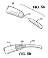
- Figs. 5a-d illustrate alternate embodiments for coupling needle 10 to guide needle 110 to implant a mesh 12 trans-abdominally as indicated above.
- the distal end of needle 10 is modified to include a bore opening 118 to allow for a press fit connection with the distal end of guide needle 110.
- bore-opening 118 may comprise other connection means, such as glue or a high-friction material.
- the distal end 17 of needle 10 is modified to include a bore opening 120 and a locking pin 122.
- Guide needle 110 is modified to include an L-shaped groove 124. The distal end of guide needle 110 inserts into opening 120 and groove 124 engages locking pin 122 and locks thereto with a quarter-turn twist.
- Fig. 5d illustrates a bore opening 126 in guide needle 110 to accept a protruding element 128 at the distal end 17 of needle 10. Protruding element 128 press fits into bore opening 126.
- the needle 10 can be used for either a trans-abdominal approach or a trans-vaginal approach.
- a kit comprising two needles 10, attached to a mesh 12, at least one coupler and at least one guide needle may be distributed for use by multiple surgeon specialists.
- a gynecologist may prefer the trans-vaginal approach and will simply discard the connector and guide needle from the kit.
- a urologist may prefer the trans-abdominal approach and utilize the connector(s) and guide needle(s).
- an alternate embodiment of the invention utilizes the needle 10 to penetrate the abdominal wall 60 and couple to the mesh 12.
- the mesh 12 is modified to create a connection means for connecting to the distal end of the needle 10.
- the connection means is preferably detachable so that when the mesh is pulled out of the abdominal wall, the mesh may be detached from the needle and the needle reused to retrieve the other end of the mesh.
- This embodiment allows for the use of a single needle for the procedure.
- This embodiment also allows for the use of a mesh constructed, at least in part, of natural materials, which are otherwise not suitable in the pre-affixed embodiment due to the inability of the natural material to survive extended periods in inventory.
- a needle 10 with coupling means at the distal end penetrates the abdominal wall 60, anterior to the pubic bone 56, Fig. 6a and follows the contour of the pubic bone 56 to one side of the urethra 54 and exits the body through an incision having been made in the anterior wall of the vagina 50, Fig. 6b.
- a first end of mesh 12 attaches to the distal end of needle 10 via coupling means. The surgeon then retracts needle 10 back through the pelvic cavity, following the same path created by needle 10, while at the same time causing mesh 12 to follow the needle, Fig. 4c.
- the needle 10 and mesh 12 pass through the vaginal wall and through the soft tissue on one side of the urethra 54.
- the needle and mesh then according to Fig. 4f being passed close to the back of the pubic bone 56, through additional layers of fat, muscle and fascia, and then out the abdominal wall 60 above the pubic bone 56.
- Needle 10 disconnects from the first mesh end, and the surgeon repeats the same procedure, but this time passes the needle 10 on the opposite side of the urethra 54, Figs. 6d-h, to complete the implantation of the mesh 12 between the mid urethra and vaginal wall.
- FIGs. 7a-g alternate embodiments for connecting the needle 10 to the mesh 12 are disclosed.
- Figs. 7a-b disclose a coupler 130 having a proximal end 132 configured to accept the mesh 12 and a distal end 134 for accepting the distal end 17 of needle 10.
- Distal end 17 comprises a contiguous groove 120 for detachably coupling with coupler 130.
- Coupler 130 further comprises two spring tabs 136 and 138, each with fingers 140 and 142 for engaging groove 120.
- Mesh 12 is preferably attached to the distal end 132 using a biocompatible glue or other appropriate mechanical fastening means.
- the surgeon may simply attach or detach needle 10 from coupler 130 by depressing spring tabs 136 and 138 forcing fingers 140 and 142 upward to allow distal end 17 to slide in or out of coupler 130. Fingers 140 and 142 engage groove 120 to hold needle 10 firmly in place within coupler 130.
- Figs. 7c-e illustrate a coupling mechanism 150 similar in function to a safety pin.
- Spring arm 152 engages with a bore 154 at the distal end 17 of needle 10.
- Figs. 7f-g illustrate a loop coupling mechanism 160 attached to mesh 12 for engaging groove 120.
- FIG. 9a-9k Another alternate embodiment of the present invention for trans-abdominally implanting mesh 12 while the patient is under local anesthesia only is shown in Figures 9a-9k. Similar to the embodiment shown in Figures 8a-8i, the alternate embodiment shown in Figures 9a-9k utilizes two needles and a guide needle.
- the guide needle is specifically an anesthesia needle 110a capable of delivering local anesthesia, which is carried therein, to the patient.
- the anesthesia needle 110a has an outer diameter that is smaller than the outer diameter of each of the needles 10a, 10b and, more particularly, is preferably about 2 mm.
- the distal ends 17a, 17b, 160a of the needles 10a, 10b and the anesthesia needle 110a, respectively, are adapted to connect with one another in a manner similar to that shown in Figures 5a and 5b. More particularly, the distal end 17a, 17b of each of the needles 10a, 10b has a bore opening 118a, 118b, respectively, that is sized and shaped for frictionally receiving the distal end 160a of the anesthesia needle 110a.
- the distal end 160a of the anesthesia needle 110a can be retained within the respective bore openings 118a, 118b by other means, including but not limited to, glue, ribbing, threading, or use of a high-friction material.
- the needles 10a, 10b and the anesthesia needle 110a could have other configurations, as discussed hereinabove, that facilitate connecting their distal ends together during the implantation procedure, such as including a separate connector element (see Figures 3a-3d) or adapting the distal ends 17a, 17b of the needles 10a, 10b to each include a bore opening and a locking pin and adapting the distal end 160a of the anesthesia needle 110a to include an L-shaped groove (not shown, but see Figure 5c).
- the anesthesia needle 110a with local anesthesia carried therein for injection into the patient, penetrates the abdominal wall 60, anterior to the pubic bone 56 and follows the contour of the pubic bone 56 to one side of the urethra 54 and exits the body through an incision having been made in the anterior wall of the vagina 50.
- the anesthesia needle 110a is paused and a clinically effective amount of local anesthetic is injected into the patient before moving the anesthesia needle 110a further along.
- the anesthesia needle 110a may be paused and local anesthetic injected as many times as the surgeon deems necessary, depending upon the condition of the patient and other clinical factors, with which persons having ordinary skill in the art will be familiar.
- the purpose of the aforesaid pauses is to anesthetize the needle pathway for a further purpose which will become clear hereinafter.
- a first one of the two needles 10a is then attached thereto by inserting the distal end 160a of the anesthesia needle 110a into the bore opening 118a of the distal end 17a of first needle 10a (see Fig. 9c). It is noted that one end of the mesh 12 is connected to the proximal end 19a of the needle 10a in any one of the ways already described hereinabove.
- the anesthesia needle 110a is then withdrawn back through the anesthetized pathway made by the anesthesia needle 110a in the patient's body, whereby the needle 10a and the tape, or mesh 12, attached thereto are also drawn through the patient's abdomen.
- the needles 10a, 110a pass through the anterior wall of the vagina 50 and through the soft tissue on one side of the urethra 54, the needles 10a, 110a being passed close to the back of the pubic bone 56, through additional layers of fat, muscle and fascia, and then out the abdominal wall 60 above the pubic bone 56, Figs. 9c and 9e.
- the diameter of the first needle 10a is significantly greater than the diameter of the anesthesia needle 110a, the fact that the pathway has already been anesthetized during the passage of the anesthesia needle 110a therethrough facilitates the retraction of the first needle 10a and mesh 12 therethrough.
- the surgeon uncouples handle 21 from the needle 10a and pulls needle 10a out of the body through the abdominal wall 60, Fig. 9f.
- this second passage of the anesthesia needle 110a into and through the patient's abdomen may or may not include pauses to inject local anesthesia into the patient, depending upon whether the first passage and paused injections accomplished sufficient anesthesia of the surgical area to enable passage of the second needle 10b and mesh 12 therethrough, as determined by clinical conditions in an manner well understood by those having ordinary skill in the art.
- the patient is able to provide feedback to the surgeon during the procedure, after the mesh 12 is in place.
- the urinary bladder 58 is filled with a fluid, such as water, using a catheter and the patient is requested to cough.
- the surgeon is able to determine the operation of the urethra and may adjust the placement of the mesh 12, as necessary, by adjusting the ends of mesh 12 located at the outside of the abdomen 60, Figs. 4h and 5h. After adjustments, the surplus mesh at the abdomen is cut off, and the ends of the mesh are secured within the abdomen and the abdomen is closed. Likewise, the incision at the vaginal wall is closed whereby the tissue flap seals the mesh between the urethra 54 and the wall of vagina 50.
- Mesh 12 is left in the body and forms an artificial ligament attached to the abdominal wall that provides the support for the urethra as required in order to restore urinary continence to the patient.
- the foregoing procedures can be performed such that the needles 10, 10a, 10b and the guide needles 110, 110a are connected to one another at their distal ends within the patient's body (not shown), rather than outside the body proximate to the vagina as shown in the various figures (see, for example, Figures 4b, 8b and 9d).
- a guiding or viewing mechanism will have to be provided so that the distal ends of the needles can be properly aligned and connected.
- Such guiding or viewing mechanisms could include well-known methods such as ultrasound, x-ray or fluorescence.
- magnets could be provided at the distal ends of the needles to facilitate their alignment with one another.
- an external mechanical aiming device or an electronic device (such as would indicate in which direction the needles must be moved to align with one another), could be developed and used satisfactorily with one or more embodiments of the present invention described hereinabove.
Abstract
Description
Claims (10)
- A surgical instrument for treating a patient suffering from female urinary stress incontinence, comprising:a) a tape for implanting into the lower abdomen of a female to provide support to the urethra, said tape having a pair of opposed ends;b) a guide element including means for delivering anesthesia to the patient's body and having a distal end;c) a curved needle element attached to proximate to one end of said tape, said needle element including a curved shaft having a distal end; andd) connecting means for removably connecting said distal end of said guide element to said distal end of said needle element.
- The surgical instrument of Claim 1, wherein said guide element is an anesthesia needle.
- The surgical instrument of Claim 2, wherein said connecting means includes a bore in said distal end of said needle element, said bore being sized and shaped to securely and removably receive said distal end of said anesthesia needle therein.
- The surgical instrument of Claim 2, wherein said distal end of said anesthesia needle has a diameter of approximately 2 millimeters.
- The surgical instrument of Claim 3, further comprising another curved needle element attached proximate to an opposite end of said tape, said another needle element including a curved shaft having a distal end; and second connecting means for removably connecting said distal end of said anesthesia needle to said distal end of said another needle element.
- The surgical instrument of Claim 5, wherein said second connecting means includes a bore in said distal end of said another needle element, said bore being sized and shaped to securely and removably receive said distal end of said anesthesia needle therein.
- The surgical instrument of Claim 6, wherein said tape is substantially flat and flexible.
- An improved surgical instrument for treating a patient suffering from female urinary stress incontinence, including a tape for implanting into the lower abdomen of a female to provide support to the urethra, said tape having a pair of ends; a first curved needle element having a distal end; a second needle element attached proximate to one end of said tape, said needle element including a curved shaft having a distal end; and connecting means for removably connecting said distal end of said first needle element to said distal end of said second needle element, the improvement wherein said first curved needle element is an anesthesia needle which includes means for delivering anesthesia to the patient's body.
- The surgical instrument of Claim 1, wherein said pair of opposed ends are made of a synthetic material and said tape includes a natural material between said pair of opposed ends.
- The surgical instrument of Claim 1, wherein said natural material is selected from the group consisting of autologous, allograft, xenograft and a tissue engineered matrix.
Applications Claiming Priority (2)
| Application Number | Priority Date | Filing Date | Title |
|---|---|---|---|
| US285281 | 1994-08-03 | ||
| US10/285,281 US6932759B2 (en) | 1999-06-09 | 2002-10-31 | Surgical instrument and method for treating female urinary incontinence |
Publications (3)
| Publication Number | Publication Date |
|---|---|
| EP1417934A2 true EP1417934A2 (en) | 2004-05-12 |
| EP1417934A3 EP1417934A3 (en) | 2006-03-29 |
| EP1417934B1 EP1417934B1 (en) | 2013-09-04 |
Family
ID=32107606
Family Applications (1)
| Application Number | Title | Priority Date | Filing Date |
|---|---|---|---|
| EP03256856.0A Expired - Lifetime EP1417934B1 (en) | 2002-10-31 | 2003-10-30 | Surgical instrument for treating female urinary incontinence |
Country Status (3)
| Country | Link |
|---|---|
| US (1) | US6932759B2 (en) |
| EP (1) | EP1417934B1 (en) |
| ES (1) | ES2436207T3 (en) |
Cited By (5)
| Publication number | Priority date | Publication date | Assignee | Title |
|---|---|---|---|---|
| WO2009018372A3 (en) * | 2007-07-30 | 2009-03-26 | Roger P Glodberg | Apparatus and method for the treatment of stress urinary incontinence |
| US8123671B2 (en) | 2005-08-04 | 2012-02-28 | C.R. Bard, Inc. | Pelvic implant systems and methods |
| US8480559B2 (en) | 2006-09-13 | 2013-07-09 | C. R. Bard, Inc. | Urethral support system |
| US8574149B2 (en) | 2007-11-13 | 2013-11-05 | C. R. Bard, Inc. | Adjustable tissue support member |
| US8845512B2 (en) | 2005-11-14 | 2014-09-30 | C. R. Bard, Inc. | Sling anchor system |
Families Citing this family (111)
| Publication number | Priority date | Publication date | Assignee | Title |
|---|---|---|---|---|
| SE506164C2 (en) * | 1995-10-09 | 1997-11-17 | Medscand Medical Ab | Instruments for the treatment of urinary incontinence in women |
| US7121997B2 (en) * | 1999-06-09 | 2006-10-17 | Ethicon, Inc. | Surgical instrument and method for treating female urinary incontinence |
| DK1581162T3 (en) | 1999-06-09 | 2011-08-01 | Ethicon Inc | Device for adjusting polymer implants on soft surfaces |
| US7226407B2 (en) | 1999-06-09 | 2007-06-05 | Ethicon, Inc. | Surgical instrument and method for treating female urinary incontinence |
| US6932759B2 (en) | 1999-06-09 | 2005-08-23 | Gene W. Kammerer | Surgical instrument and method for treating female urinary incontinence |
| US7131943B2 (en) * | 2000-03-09 | 2006-11-07 | Ethicon, Inc. | Surgical instrument and method for treating organ prolapse conditions |
| DE10019604C2 (en) * | 2000-04-20 | 2002-06-27 | Ethicon Gmbh | implant |
| US6638211B2 (en) * | 2000-07-05 | 2003-10-28 | Mentor Corporation | Method for treating urinary incontinence in women and implantable device intended to correct urinary incontinence |
| FR2811218B1 (en) | 2000-07-05 | 2003-02-28 | Patrice Suslian | IMPLANTABLE DEVICE FOR CORRECTING URINARY INCONTINENCE |
| US8167785B2 (en) | 2000-10-12 | 2012-05-01 | Coloplast A/S | Urethral support system |
| US20060205995A1 (en) | 2000-10-12 | 2006-09-14 | Gyne Ideas Limited | Apparatus and method for treating female urinary incontinence |
| GB0025068D0 (en) | 2000-10-12 | 2000-11-29 | Browning Healthcare Ltd | Apparatus and method for treating female urinary incontinence |
| US6612977B2 (en) | 2001-01-23 | 2003-09-02 | American Medical Systems Inc. | Sling delivery system and method of use |
| US7070556B2 (en) | 2002-03-07 | 2006-07-04 | Ams Research Corporation | Transobturator surgical articles and methods |
| US6641525B2 (en) | 2001-01-23 | 2003-11-04 | Ams Research Corporation | Sling assembly with secure and convenient attachment |
| GB0108088D0 (en) | 2001-03-30 | 2001-05-23 | Browning Healthcare Ltd | Surgical implant |
| US7087065B2 (en) * | 2001-10-04 | 2006-08-08 | Ethicon, Inc. | Mesh for pelvic floor repair |
| MXPA04008407A (en) * | 2002-03-01 | 2005-12-12 | Ethicon Inc | Method and apparatus for treating pelvic organ prolapses in female patients. |
| CA2478448C (en) * | 2002-03-07 | 2011-06-21 | Ams Research Corporation | Transobturator surgical articles and methods |
| US6911003B2 (en) | 2002-03-07 | 2005-06-28 | Ams Research Corporation | Transobturator surgical articles and methods |
| CA2492630C (en) | 2002-08-02 | 2009-01-13 | C.R. Bard, Inc. | Self anchoring sling and introducer system |
| US7637384B2 (en) * | 2002-08-09 | 2009-12-29 | Crown Packaging Technology, Inc. | Tamper evident closure with locking band and container therefor |
| GB0307082D0 (en) | 2003-03-27 | 2003-04-30 | Gyne Ideas Ltd | Drug delivery device and method |
| US7288092B2 (en) * | 2003-04-23 | 2007-10-30 | Atricure, Inc. | Method and apparatus for ablating cardiac tissue with guide facility |
| US6981944B2 (en) * | 2003-07-07 | 2006-01-03 | Ethicon, Inc. | Implantable surgical mesh having a lubricious coating |
| US7347812B2 (en) | 2003-09-22 | 2008-03-25 | Ams Research Corporation | Prolapse repair |
| AU2004279388B2 (en) | 2003-10-03 | 2010-10-14 | Boston Scientific Limited | Systems for a delivering a medical implant to an anatomical location in a patient |
| US7524281B2 (en) * | 2003-11-17 | 2009-04-28 | Boston Scientific Scimed, Inc. | Systems and methods relating to associating a medical implant with a delivery device |
| WO2005086564A2 (en) * | 2004-03-13 | 2005-09-22 | Tissue Science Laboratories Plc | Surgical instrument |
| US7351197B2 (en) | 2004-05-07 | 2008-04-01 | Ams Research Corporation | Method and apparatus for cystocele repair |
| US7811222B2 (en) | 2004-04-30 | 2010-10-12 | Ams Research Corporation | Method and apparatus for treating pelvic organ prolapse |
| US7500945B2 (en) | 2004-04-30 | 2009-03-10 | Ams Research Corporation | Method and apparatus for treating pelvic organ prolapse |
| US8062206B2 (en) | 2004-05-07 | 2011-11-22 | Ams Research Corporation | Method and apparatus for treatment of vaginal anterior repairs |
| US8047982B2 (en) * | 2004-05-07 | 2011-11-01 | Ethicon, Inc. | Mesh tape with wing-like extensions for treating female urinary incontinence |
| GB0411360D0 (en) | 2004-05-21 | 2004-06-23 | Mpathy Medical Devices Ltd | Implant |
| FR2871361B1 (en) * | 2004-06-15 | 2006-09-29 | Analytic Biosurgical Solutions | SURGICAL ANCHORING DEVICE |
| KR101259770B1 (en) * | 2004-07-28 | 2013-05-03 | 에디컨인코포레이티드 | Minimally invasive medical implant and insertion device and method for using the same |
| US7527588B2 (en) * | 2004-09-15 | 2009-05-05 | Ethicon, Inc. | System and method for surgical implant placement |
| AU2004324479A1 (en) * | 2004-10-25 | 2006-05-04 | Boston Scientific Limited | Systems and methods for sling delivery and placement |
| US20060149121A1 (en) * | 2005-01-03 | 2006-07-06 | Hughett James D Sr | Instrument guide and method for use |
| US8029528B2 (en) * | 2005-01-03 | 2011-10-04 | Atricure, Inc. | Instrument guide and method for use |
| US7481314B2 (en) * | 2005-02-02 | 2009-01-27 | Ethicon, Inc. | Packaging assembly for surgical mesh implants |
| US7393320B2 (en) | 2005-04-29 | 2008-07-01 | Ams Research Corporation | Pelvic floor health articles and procedures |
| US20100094079A1 (en) | 2005-06-21 | 2010-04-15 | Ams Research Corporation | Method and Apparatus for Securing a Urethral Sling to Pubic Bone |
| US8864650B2 (en) | 2005-06-21 | 2014-10-21 | Ams Research Corporation | Methods and apparatus for securing a urethral sling to a pubic bone |
| CA2550752C (en) * | 2005-06-28 | 2014-09-09 | Sherwood Services Ag | Illuminated ivs tunneling device |
| US8535217B2 (en) | 2005-07-26 | 2013-09-17 | Ams Research Corporation | Methods and systems for treatment of prolapse |
| US7878970B2 (en) | 2005-09-28 | 2011-02-01 | Boston Scientific Scimed, Inc. | Apparatus and method for suspending a uterus |
| US7637860B2 (en) * | 2005-11-16 | 2009-12-29 | Boston Scientific Scimed, Inc. | Devices for minimally invasive pelvic surgery |
| US9144483B2 (en) | 2006-01-13 | 2015-09-29 | Boston Scientific Scimed, Inc. | Placing fixation devices |
| US9078727B2 (en) | 2006-03-16 | 2015-07-14 | Boston Scientific Scimed, Inc. | System and method for treating tissue wall prolapse |
| WO2007137226A2 (en) | 2006-05-19 | 2007-11-29 | Ams Research Corporation | Method and articles for treatment of stress urinary incontinence |
| CA2654966A1 (en) | 2006-06-16 | 2007-12-27 | Ams Research Corporation | Surgical implants and tools for treating pelvic conditions |
| WO2007149555A2 (en) | 2006-06-22 | 2007-12-27 | Ams Research Corporation | Adjustable tension incontinence sling assemblies |
| US20080082177A1 (en) * | 2006-09-29 | 2008-04-03 | Chunlin Yang | Device for tissue reinforcement having microporous and macroporous structures |
| US8951185B2 (en) | 2007-10-26 | 2015-02-10 | Ams Research Corporation | Surgical articles and methods for treating pelvic conditions |
| CN101528139B (en) | 2006-10-26 | 2014-10-01 | Ams研究公司 | Surgical articles for treating pelvic conditions |
| CN101842060B (en) | 2007-09-21 | 2014-07-16 | Ams研究公司 | Pelvic floor treatments and related tools and implants |
| US8623034B2 (en) | 2007-10-19 | 2014-01-07 | Ethicon, Gmbh | Soft tissue repair implant |
| CA2708283A1 (en) * | 2007-12-14 | 2009-06-25 | Vonyoon Enterprises, Llc | Endoscopic mesh delivery system with integral mesh stabilizer and vaginal probe |
| US9078728B2 (en) | 2007-12-28 | 2015-07-14 | Boston Scientific Scimed, Inc. | Devices and methods for delivering female pelvic floor implants |
| US9282958B2 (en) | 2007-12-28 | 2016-03-15 | Boston Scientific Scimed, Inc. | Devices and method for treating pelvic dysfunctions |
| US8430807B2 (en) | 2007-12-28 | 2013-04-30 | Boston Scientific Scimed, Inc. | Devices and methods for treating pelvic floor dysfunctions |
| US8727963B2 (en) | 2008-07-31 | 2014-05-20 | Ams Research Corporation | Methods and implants for treating urinary incontinence |
| WO2010027796A1 (en) | 2008-08-25 | 2010-03-11 | Ams Research Corporation | Minimally invasive implant and method |
| US9017243B2 (en) | 2008-08-25 | 2015-04-28 | Ams Research Corporation | Minimally invasive implant and method |
| US8545513B2 (en) * | 2008-10-24 | 2013-10-01 | Coopersurgical, Inc. | Uterine manipulator assemblies and related components and methods |
| EP3424437A1 (en) | 2008-10-27 | 2019-01-09 | Boston Scientific Scimed, Inc. | Surgical needle and anchor system with retractable features |
| US8449573B2 (en) | 2008-12-05 | 2013-05-28 | Boston Scientific Scimed, Inc. | Insertion device and method for delivery of a mesh carrier |
| US8821372B2 (en) * | 2008-12-12 | 2014-09-02 | Walter von Pechmann | Endoscopic mesh delivery system with integral mesh stabilizer and vaginal probe |
| WO2010093421A2 (en) | 2009-02-10 | 2010-08-19 | Ams Research Corporation | Surgical articles and methods for treating urinary incontinence |
| US9125716B2 (en) | 2009-04-17 | 2015-09-08 | Boston Scientific Scimed, Inc. | Delivery sleeve for pelvic floor implants |
| US8968334B2 (en) * | 2009-04-17 | 2015-03-03 | Boston Scientific Scimed, Inc. | Apparatus for delivering and anchoring implantable medical devices |
| US8292901B2 (en) * | 2009-05-27 | 2012-10-23 | Coopersurgical, Inc. | Uterine manipulators and related components and methods |
| US8298187B2 (en) | 2009-07-07 | 2012-10-30 | Cook Medical Technologies Llc | Fluid injection device |
| US9301750B2 (en) | 2009-11-03 | 2016-04-05 | Boston Scientific Scimed, Inc. | Device and method for delivery of mesh-based devices |
| US9364308B2 (en) | 2009-12-30 | 2016-06-14 | Astora Women's Health, Llc | Implant systems with tensioning feedback |
| CA2785830A1 (en) | 2009-12-30 | 2011-07-07 | Ams Research Corporation | Implantable sling systems and methods |
| US9393091B2 (en) | 2009-12-31 | 2016-07-19 | Astora Women's Health, Llc | Suture-less tissue fixation for implantable device |
| US9277936B2 (en) * | 2010-01-11 | 2016-03-08 | Kenneth Finkelstein | Surgical instrument having an integrated local anesthetic delivery system |
| EP3721832B1 (en) | 2010-02-23 | 2023-03-29 | Boston Scientific Scimed, Inc. | Surgical articles for treating incontinence |
| US9445881B2 (en) | 2010-02-23 | 2016-09-20 | Boston Scientific Scimed, Inc. | Surgical articles and methods |
| US10028813B2 (en) | 2010-07-22 | 2018-07-24 | Boston Scientific Scimed, Inc. | Coated pelvic implant device and method |
| US8911348B2 (en) | 2010-09-02 | 2014-12-16 | Boston Scientific Scimed, Inc. | Pelvic implants and methods of implanting the same |
| US8939988B2 (en) | 2010-11-01 | 2015-01-27 | Coopersurgical, Inc. | Uterine manipulators and related components and methods |
| US8439850B2 (en) | 2010-11-01 | 2013-05-14 | Coopersurgical, Inc. | Cervical sizing devices and related kits and methods |
| US9271754B2 (en) | 2010-12-16 | 2016-03-01 | Boston Scientific Scimed, Inc. | Movable curved needle for delivering implants and methods of delivering implants |
| US9572648B2 (en) | 2010-12-21 | 2017-02-21 | Justin M. Crank | Implantable slings and anchor systems |
| US9381075B2 (en) | 2011-01-31 | 2016-07-05 | Boston Scientific Scimed, Inc. | Deflection member for delivering implants and methods of delivering implants |
| US9622848B2 (en) | 2011-02-23 | 2017-04-18 | Boston Scientific Scimed, Inc. | Urethral stent system and method |
| US8808162B2 (en) | 2011-03-28 | 2014-08-19 | Ams Research Corporation | Implants, tools, and methods for treatment of pelvic conditions |
| US10034735B2 (en) | 2011-03-28 | 2018-07-31 | Boston Scientific Scimed, Inc. | Implants, tools, and methods for treatments of pelvic conditions |
| US9089393B2 (en) | 2011-03-28 | 2015-07-28 | Ams Research Corporation | Implants, tools, and methods for treatment of pelvic conditions |
| US9492259B2 (en) | 2011-03-30 | 2016-11-15 | Astora Women's Health, Llc | Expandable implant system |
| US10058240B2 (en) | 2011-06-29 | 2018-08-28 | Boston Scientific Scimed, Inc. | Systems, implants, tools, and methods for treatments of pelvic conditions |
| US9351723B2 (en) | 2011-06-30 | 2016-05-31 | Astora Women's Health, Llc | Implants, tools, and methods for treatments of pelvic conditions |
| EP2734148B1 (en) | 2011-07-22 | 2019-06-05 | Boston Scientific Scimed, Inc. | Pelvic implant system |
| US9414903B2 (en) | 2011-07-22 | 2016-08-16 | Astora Women's Health, Llc | Pelvic implant system and method |
| US9492191B2 (en) | 2011-08-04 | 2016-11-15 | Astora Women's Health, Llc | Tools and methods for treatment of pelvic conditions |
| US20130035555A1 (en) | 2011-08-05 | 2013-02-07 | Alexander James A | Systems, implants, tools, and methods for treatment of pelvic conditions |
| US8840077B2 (en) | 2011-08-24 | 2014-09-23 | Coopersurgical, Inc. | Table-mounted surgical instrument stabilizers |
| US10098721B2 (en) | 2011-09-01 | 2018-10-16 | Boston Scientific Scimed, Inc. | Pelvic implant needle system and method |
| US9345472B2 (en) | 2011-09-02 | 2016-05-24 | Boston Scientific Scimed, Inc. | Multi-arm tool for delivering implants and methods thereof |
| US9168120B2 (en) | 2011-09-09 | 2015-10-27 | Boston Scientific Scimed, Inc. | Medical device and methods of delivering the medical device |
| EP2633876B1 (en) | 2012-03-02 | 2014-09-24 | Cook Medical Technologies LLC | Dilation cap for endoluminal device |
| US9044223B2 (en) | 2012-06-05 | 2015-06-02 | Ethicon, Inc. | Implant insertion systems and methods of use |
| US9814555B2 (en) | 2013-03-12 | 2017-11-14 | Boston Scientific Scimed, Inc. | Medical device for pelvic floor repair and method of delivering the medical device |
| US9962251B2 (en) | 2013-10-17 | 2018-05-08 | Boston Scientific Scimed, Inc. | Devices and methods for delivering implants |
| WO2015116724A1 (en) * | 2014-01-28 | 2015-08-06 | Invuity, Inc. | Drop in surgical illuminator |
| US9636144B2 (en) | 2014-10-09 | 2017-05-02 | Coopersurgical, Inc. | Uterine manipulators and related components and methods |
| US10932819B2 (en) | 2018-04-18 | 2021-03-02 | Coopersurgical, Inc. | Uterine manipulators and related components and methods |
Citations (4)
| Publication number | Priority date | Publication date | Assignee | Title |
|---|---|---|---|---|
| US5899909A (en) * | 1994-08-30 | 1999-05-04 | Medscand Medical Ab | Surgical instrument for treating female urinary incontinence |
| WO2000074613A1 (en) * | 1999-06-09 | 2000-12-14 | Ethicon, Inc. | Visually-directed surgical instrument and method for treating female urinary incontinence |
| US20010018549A1 (en) * | 2000-01-21 | 2001-08-30 | Victor Scetbon | Percutaneous device and method for treating urinary stress incontinence in women using a sub-urethral tape |
| WO2002058564A2 (en) * | 2001-01-23 | 2002-08-01 | American Medical Systems, Inc. | Surgical articles |
Family Cites Families (82)
| Publication number | Priority date | Publication date | Assignee | Title |
|---|---|---|---|---|
| US3182662A (en) | 1962-07-25 | 1965-05-11 | Vithal N Shirodkar | Plastic prosthesis useful in gynaecological surgery |
| US3212502A (en) | 1963-01-25 | 1965-10-19 | Hu C Myers | Knotless adhesive impregnated sutures and method of use thereof |
| US3311110A (en) | 1964-07-15 | 1967-03-28 | American Cyanamid Co | Flexible composite suture having a tandem linkage |
| US3372695A (en) | 1965-04-27 | 1968-03-12 | Prosit Service Corp | Method of overcoming incontinence |
| US3472232A (en) | 1967-05-31 | 1969-10-14 | Abbott Lab | Catheter insertion device |
| US3608095A (en) | 1970-03-05 | 1971-09-28 | Federal Tool Eng Co | Method of fixing hair pieces to scalps |
| US3763860A (en) | 1971-08-26 | 1973-10-09 | H Clarke | Laparoscopy instruments and method for suturing and ligation |
| US3858783A (en) | 1972-11-20 | 1975-01-07 | Nikolai Nikolaevich Kapitanov | Surgical instrument for stitching up tissues with lengths of suture wire |
| US3924633A (en) | 1974-01-31 | 1975-12-09 | Cook Inc | Apparatus and method for suprapubic catheterization |
| US4037603A (en) | 1975-05-13 | 1977-07-26 | Wendorff Erwin R | Metallic surgical suture |
| US4128100A (en) | 1976-10-08 | 1978-12-05 | Wendorff Erwin R | Suture |
| US4235238A (en) | 1978-05-11 | 1980-11-25 | Olympus Optical Co., Ltd. | Apparatus for suturing coeliac tissues |
| US4392495A (en) | 1981-08-31 | 1983-07-12 | Bayers Jon Herbert | Apparatus for and method of suturing tissue |
| US4441497A (en) | 1982-10-21 | 1984-04-10 | Paudler Franklin T | Universal suture passer |
| US4509516A (en) | 1983-02-24 | 1985-04-09 | Stryker Corporation | Ligament tunneling instrument |
| US4549545A (en) | 1984-03-05 | 1985-10-29 | Ethicon Inc. | Segmented polyurethane surgical buttressing pledgets |
| US5032508A (en) | 1988-09-08 | 1991-07-16 | Marrow-Tech, Inc. | Three-dimensional cell and tissue culture system |
| JPH0431072Y2 (en) | 1988-03-14 | 1992-07-27 | ||
| BR8907704A (en) | 1988-10-04 | 1991-07-30 | Petros Peter E | SURGICAL INSTRUMENT PROSTHESIS AND METHOD FOR ITS USE |
| US5013292A (en) | 1989-02-24 | 1991-05-07 | R. Laborie Medical Corporation | Surgical correction of female urinary stress incontinence and kit therefor |
| US5441508A (en) | 1989-04-27 | 1995-08-15 | Gazielly; Dominique | Reinforcement and supporting device for the rotator cuff of a shoulder joint of a person |
| US5080667A (en) | 1989-11-13 | 1992-01-14 | Ethicon, Inc. | Sterile surgical needle-suture combination |
| US5368595A (en) | 1990-09-06 | 1994-11-29 | United States Surgical Corporation | Implant assist apparatus |
| CA2049103C (en) | 1990-09-06 | 1996-10-01 | Royce Lewis | Implant assist apparatus |
| US5439467A (en) | 1991-12-03 | 1995-08-08 | Vesica Medical, Inc. | Suture passer |
| WO1993010715A2 (en) | 1991-12-03 | 1993-06-10 | Vesitec Medical, Inc. | Surgical treatment of stress urinary incontinence |
| JP3192147B2 (en) | 1991-12-03 | 2001-07-23 | ボストン サイエンティフィック アイルランド リミテッド,バーバドス ヘッド オフィス | Bone anchor insertion device |
| US5935122A (en) | 1991-12-13 | 1999-08-10 | Endovascular Technologies, Inc. | Dual valve, flexible expandable sheath and method |
| WO1993019147A1 (en) | 1992-03-16 | 1993-09-30 | The Procter & Gamble Company | Fabric softening compositions containing mixtures of softener material and highly ethoxylated curd dispersant |
| US5411481A (en) | 1992-04-08 | 1995-05-02 | American Cyanamid Co. | Surgical purse string suturing instrument and method |
| US5403328A (en) | 1992-04-22 | 1995-04-04 | United States Surgical Corporation | Surgical apparatus and method for suturing body tissue |
| US5180385A (en) | 1992-05-21 | 1993-01-19 | Sidney Sontag | Suturing assembly and method |
| DE4220283C2 (en) | 1992-06-20 | 1994-05-19 | Singer Spezialnadelfab | Surgical needle-thread combination |
| US5362294A (en) | 1992-09-25 | 1994-11-08 | Seitzinger Michael R | Sling for positioning internal organ during laparoscopic surgery and method of use |
| US5281237A (en) | 1992-09-25 | 1994-01-25 | Gimpelson Richard J | Surgical stitching device and method of use |
| US5337736A (en) | 1992-09-30 | 1994-08-16 | Reddy Pratap K | Method of using a laparoscopic retractor |
| US5383904A (en) | 1992-10-13 | 1995-01-24 | United States Surgical Corporation | Stiffened surgical device |
| US5250033A (en) | 1992-10-28 | 1993-10-05 | Interventional Thermodynamics, Inc. | Peel-away introducer sheath having proximal fitting |
| US5972000A (en) | 1992-11-13 | 1999-10-26 | Influence Medical Technologies, Ltd. | Non-linear anchor inserter device and bone anchors |
| US5540703A (en) | 1993-01-06 | 1996-07-30 | Smith & Nephew Richards Inc. | Knotted cable attachment apparatus formed of braided polymeric fibers |
| US5855549A (en) | 1993-08-18 | 1999-01-05 | Vista Medical Technologies, Inc. | Method of using an optical female urethroscope |
| US5450860A (en) | 1993-08-31 | 1995-09-19 | W. L. Gore & Associates, Inc. | Device for tissue repair and method for employing same |
| DE4334419C2 (en) | 1993-10-08 | 1996-10-17 | Univ Ludwigs Albert | Surgical tool for orchidopexy |
| US5507796A (en) | 1994-04-28 | 1996-04-16 | Hasson; Harrith M. | Method of suspending a pelvic organ and instrument for performing the method |
| US5595836A (en) | 1994-06-14 | 1997-01-21 | Matsushita Electric Industrial Co., Ltd. | Manganese dry battery |
| US5618800A (en) | 1994-08-30 | 1997-04-08 | Alcon Laboratories, Inc. | Thermally-gelling drug delivery vehicles containing cellulose ethers |
| SE503271C2 (en) | 1994-08-30 | 1996-04-29 | Medscand Ab | Instruments for the treatment of urinary incontinence in women and methods for such treatment |
| SE506164C2 (en) | 1995-10-09 | 1997-11-17 | Medscand Medical Ab | Instruments for the treatment of urinary incontinence in women |
| US5997554A (en) | 1995-06-14 | 1999-12-07 | Medworks Corporation | Surgical template and surgical method employing same |
| DE19544162C1 (en) | 1995-11-17 | 1997-04-24 | Ethicon Gmbh | Implant for suspension of the bladder in urinary incontinence in women |
| US5645568A (en) | 1995-11-20 | 1997-07-08 | Medicinelodge, Inc. | Expandable body suture |
| US5816258A (en) | 1996-06-13 | 1998-10-06 | General Surgical Innovations, Inc. | Bladder neck suspension method |
| WO1998007409A1 (en) | 1996-08-23 | 1998-02-26 | Sequus Pharmaceuticals, Inc. | Liposomes containing a cisplatin compound |
| US5899999A (en) | 1996-10-16 | 1999-05-04 | Microsoft Corporation | Iterative convolution filter particularly suited for use in an image classification and retrieval system |
| WO1998031301A1 (en) | 1997-01-15 | 1998-07-23 | Lenadora Shantha Jayatilake Ba | Device for genuine stress incontinence in the female |
| JP2001511685A (en) | 1997-02-13 | 2001-08-14 | ボストン サイエンティフィック リミテッド | Stabilized sling for use in minimally invasive pelvic surgery |
| US5741299A (en) | 1997-03-05 | 1998-04-21 | Rudt; Louis L. | Puncture-proof suture needle assembly |
| US5934283A (en) | 1997-04-15 | 1999-08-10 | Uroplasty, Inc. | Pubovaginal sling device |
| US6221005B1 (en) | 1998-02-17 | 2001-04-24 | Norman I. Bruckner | Pubo-urethral support harness apparatus for percutaneous treatment of female stress urinary incontinence with urethal hypemobility |
| ES2149091B1 (en) | 1998-03-10 | 2001-05-16 | Gil Vernet Vila Jose Maria | DEVICE FOR FIXING AND ADJUSTABLE SUPPORT AT HEIGHT OF INTERNAL ANATOMICAL ORGANS. |
| US6382214B1 (en) | 1998-04-24 | 2002-05-07 | American Medical Systems, Inc. | Methods and apparatus for correction of urinary and gynecological pathologies including treatment of male incontinence and female cystocele |
| US6010447A (en) | 1998-07-31 | 2000-01-04 | Kardjian; Paul M. | Bladder sling |
| US6042536A (en) | 1998-08-13 | 2000-03-28 | Contimed, Inc. | Bladder sling |
| US6030393A (en) | 1998-09-15 | 2000-02-29 | Corlew; Earvin L. | Needle and procedure for relieving urinary incontinence |
| US6050937A (en) | 1998-09-21 | 2000-04-18 | Benderev; Theodore V. | Surgical tension/pressure monitor |
| EP1025811A3 (en) | 1999-02-05 | 2001-05-09 | Medtronic, Inc. | Endoluminal prosthesis having radiopaque marker |
| US6273852B1 (en) | 1999-06-09 | 2001-08-14 | Ethicon, Inc. | Surgical instrument and method for treating female urinary incontinence |
| US6932759B2 (en) | 1999-06-09 | 2005-08-23 | Gene W. Kammerer | Surgical instrument and method for treating female urinary incontinence |
| US7226407B2 (en) | 1999-06-09 | 2007-06-05 | Ethicon, Inc. | Surgical instrument and method for treating female urinary incontinence |
| US7121997B2 (en) | 1999-06-09 | 2006-10-17 | Ethicon, Inc. | Surgical instrument and method for treating female urinary incontinence |
| IT1313574B1 (en) | 1999-07-27 | 2002-09-09 | Angiologica B M S R L | CORRECTIVE NETWORK FOR BODY FABRICS. |
| US6306079B1 (en) | 1999-12-07 | 2001-10-23 | Arnaldo F. Trabucco | Mesh pubovaginal sling |
| US6406423B1 (en) | 2000-01-21 | 2002-06-18 | Sofradim Production | Method for surgical treatment of urinary incontinence and device for carrying out said method |
| US7131943B2 (en) | 2000-03-09 | 2006-11-07 | Ethicon, Inc. | Surgical instrument and method for treating organ prolapse conditions |
| US6592515B2 (en) | 2000-09-07 | 2003-07-15 | Ams Research Corporation | Implantable article and method |
| AU2001293085B2 (en) | 2000-09-26 | 2006-06-01 | Ethicon, Inc. | Surgical apparatus and methods for delivery of a sling in the treatment of female urinary incontinence |
| FR2814939B1 (en) | 2000-10-05 | 2002-12-20 | Sofradim Production | SUB-URETRAL SUPPORT KIT FOR THE TREATMENT OF URINARY INCONTINENCE OF FEMALE EXERCISE |
| US6605097B1 (en) | 2000-10-18 | 2003-08-12 | Jorn Lehe | Apparatus and method for treating female urinary incontinence |
| AU2002217880A1 (en) | 2000-11-15 | 2002-05-27 | Scimed Life Systems, Inc. | Device and method for treating female urinary incontinence |
| US6612977B2 (en) | 2001-01-23 | 2003-09-02 | American Medical Systems Inc. | Sling delivery system and method of use |
| US7407480B2 (en) | 2001-07-27 | 2008-08-05 | Ams Research Corporation | Method and apparatus for correction of urinary and gynecological pathologies, including treatment of incontinence cystocele |
| MXPA04008407A (en) | 2002-03-01 | 2005-12-12 | Ethicon Inc | Method and apparatus for treating pelvic organ prolapses in female patients. |
-
2002
- 2002-10-31 US US10/285,281 patent/US6932759B2/en not_active Expired - Lifetime
-
2003
- 2003-10-30 ES ES03256856T patent/ES2436207T3/en not_active Expired - Lifetime
- 2003-10-30 EP EP03256856.0A patent/EP1417934B1/en not_active Expired - Lifetime
Patent Citations (4)
| Publication number | Priority date | Publication date | Assignee | Title |
|---|---|---|---|---|
| US5899909A (en) * | 1994-08-30 | 1999-05-04 | Medscand Medical Ab | Surgical instrument for treating female urinary incontinence |
| WO2000074613A1 (en) * | 1999-06-09 | 2000-12-14 | Ethicon, Inc. | Visually-directed surgical instrument and method for treating female urinary incontinence |
| US20010018549A1 (en) * | 2000-01-21 | 2001-08-30 | Victor Scetbon | Percutaneous device and method for treating urinary stress incontinence in women using a sub-urethral tape |
| WO2002058564A2 (en) * | 2001-01-23 | 2002-08-01 | American Medical Systems, Inc. | Surgical articles |
Cited By (7)
| Publication number | Priority date | Publication date | Assignee | Title |
|---|---|---|---|---|
| US8123671B2 (en) | 2005-08-04 | 2012-02-28 | C.R. Bard, Inc. | Pelvic implant systems and methods |
| US8845512B2 (en) | 2005-11-14 | 2014-09-30 | C. R. Bard, Inc. | Sling anchor system |
| US8480559B2 (en) | 2006-09-13 | 2013-07-09 | C. R. Bard, Inc. | Urethral support system |
| WO2009018372A3 (en) * | 2007-07-30 | 2009-03-26 | Roger P Glodberg | Apparatus and method for the treatment of stress urinary incontinence |
| US9402705B2 (en) | 2007-07-30 | 2016-08-02 | Boston Scientific Scimed, Inc. | Apparatus and method for the treatment of stress urinary incontinence |
| US10413392B2 (en) | 2007-07-30 | 2019-09-17 | Boston Scientific Scimed, Inc. | Apparatus and method for the treatment of stress urinary incontinence |
| US8574149B2 (en) | 2007-11-13 | 2013-11-05 | C. R. Bard, Inc. | Adjustable tissue support member |
Also Published As
| Publication number | Publication date |
|---|---|
| EP1417934A3 (en) | 2006-03-29 |
| EP1417934B1 (en) | 2013-09-04 |
| US20030149440A1 (en) | 2003-08-07 |
| US6932759B2 (en) | 2005-08-23 |
| ES2436207T3 (en) | 2013-12-27 |
Similar Documents
| Publication | Publication Date | Title |
|---|---|---|
| CA2449474C (en) | Surgical instrument kit for treating urinary incontinence | |
| US6932759B2 (en) | Surgical instrument and method for treating female urinary incontinence | |
| US7226407B2 (en) | Surgical instrument and method for treating female urinary incontinence | |
| AU2002345375A1 (en) | Surgical instrument kit for treating female urinary incontinence | |
| CA2475910C (en) | Surgical instrument and method for treating organ prolapse conditions | |
| US7070556B2 (en) | Transobturator surgical articles and methods | |
| US6596001B2 (en) | Aiming device for surgical instrument and method for use for treating female urinary incontinence | |
| EP1194091B1 (en) | Visually-directed surgical instrument for treating female urinary incontinence | |
| CA2376278C (en) | Surgical instrument and method for treating female urinary incontinence | |
| EP1201189A2 (en) | Light-assisted surgical instrument and method for treating female urinary incontinence |
Legal Events
| Date | Code | Title | Description |
|---|---|---|---|
| PUAI | Public reference made under article 153(3) epc to a published international application that has entered the european phase |
Free format text: ORIGINAL CODE: 0009012 |
|
| AK | Designated contracting states |
Kind code of ref document: A2 Designated state(s): AT BE BG CH CY CZ DE DK EE ES FI FR GB GR HU IE IT LI LU MC NL PT RO SE SI SK TR |
|
| AX | Request for extension of the european patent |
Extension state: AL LT LV MK |
|
| PUAL | Search report despatched |
Free format text: ORIGINAL CODE: 0009013 |
|
| AK | Designated contracting states |
Kind code of ref document: A3 Designated state(s): AT BE BG CH CY CZ DE DK EE ES FI FR GB GR HU IE IT LI LU MC NL PT RO SE SI SK TR |
|
| AX | Request for extension of the european patent |
Extension state: AL LT LV MK |
|
| 17P | Request for examination filed |
Effective date: 20060908 |
|
| AKX | Designation fees paid |
Designated state(s): AT BE BG CH CY CZ DE DK EE ES FI FR GB GR HU IE IT LI LU MC NL PT RO SE SI SK TR |
|
| 17Q | First examination report despatched |
Effective date: 20061201 |
|
| REG | Reference to a national code |
Ref country code: DE Ref legal event code: R079 Ref document number: 60344848 Country of ref document: DE Free format text: PREVIOUS MAIN CLASS: A61B0017040000 Ipc: A61B0017060000 |
|
| GRAP | Despatch of communication of intention to grant a patent |
Free format text: ORIGINAL CODE: EPIDOSNIGR1 |
|
| RIC1 | Information provided on ipc code assigned before grant |
Ipc: A61F 2/00 20060101ALI20130308BHEP Ipc: A61B 1/307 20060101ALI20130308BHEP Ipc: A61B 1/00 20060101ALI20130308BHEP Ipc: A61B 17/04 20060101ALI20130308BHEP Ipc: A61B 17/06 20060101AFI20130308BHEP |
|
| INTG | Intention to grant announced |
Effective date: 20130417 |
|
| GRAS | Grant fee paid |
Free format text: ORIGINAL CODE: EPIDOSNIGR3 |
|
| GRAA | (expected) grant |
Free format text: ORIGINAL CODE: 0009210 |
|
| AK | Designated contracting states |
Kind code of ref document: B1 Designated state(s): AT BE BG CH CY CZ DE DK EE ES FI FR GB GR HU IE IT LI LU MC NL PT RO SE SI SK TR |
|
| REG | Reference to a national code |
Ref country code: GB Ref legal event code: FG4D |
|
| REG | Reference to a national code |
Ref country code: CH Ref legal event code: EP |
|
| REG | Reference to a national code |
Ref country code: AT Ref legal event code: REF Ref document number: 630026 Country of ref document: AT Kind code of ref document: T Effective date: 20130915 |
|
| REG | Reference to a national code |
Ref country code: IE Ref legal event code: FG4D |
|
| PGFP | Annual fee paid to national office [announced via postgrant information from national office to epo] |
Ref country code: MC Payment date: 20130926 Year of fee payment: 11 |
|
| REG | Reference to a national code |
Ref country code: DE Ref legal event code: R096 Ref document number: 60344848 Country of ref document: DE Effective date: 20131031 |
|
| REG | Reference to a national code |
Ref country code: ES Ref legal event code: FG2A Ref document number: 2436207 Country of ref document: ES Kind code of ref document: T3 Effective date: 20131227 |
|
| PGFP | Annual fee paid to national office [announced via postgrant information from national office to epo] |
Ref country code: DK Payment date: 20131010 Year of fee payment: 11 Ref country code: LU Payment date: 20131112 Year of fee payment: 11 |
|
| REG | Reference to a national code |
Ref country code: AT Ref legal event code: MK05 Ref document number: 630026 Country of ref document: AT Kind code of ref document: T Effective date: 20130904 |
|
| REG | Reference to a national code |
Ref country code: NL Ref legal event code: VDEP Effective date: 20130904 |
|
| PG25 | Lapsed in a contracting state [announced via postgrant information from national office to epo] |
Ref country code: SE Free format text: LAPSE BECAUSE OF FAILURE TO SUBMIT A TRANSLATION OF THE DESCRIPTION OR TO PAY THE FEE WITHIN THE PRESCRIBED TIME-LIMIT Effective date: 20130904 Ref country code: CY Free format text: LAPSE BECAUSE OF FAILURE TO SUBMIT A TRANSLATION OF THE DESCRIPTION OR TO PAY THE FEE WITHIN THE PRESCRIBED TIME-LIMIT Effective date: 20130703 |
|
| PGFP | Annual fee paid to national office [announced via postgrant information from national office to epo] |
Ref country code: BE Payment date: 20131014 Year of fee payment: 11 Ref country code: CH Payment date: 20131014 Year of fee payment: 11 Ref country code: AT Payment date: 20130926 Year of fee payment: 11 |
|
| REG | Reference to a national code |
Ref country code: NL Ref legal event code: VDEP Effective date: 20130904 |
|
| PG25 | Lapsed in a contracting state [announced via postgrant information from national office to epo] |
Ref country code: GR Free format text: LAPSE BECAUSE OF FAILURE TO SUBMIT A TRANSLATION OF THE DESCRIPTION OR TO PAY THE FEE WITHIN THE PRESCRIBED TIME-LIMIT Effective date: 20131205 Ref country code: SI Free format text: LAPSE BECAUSE OF FAILURE TO SUBMIT A TRANSLATION OF THE DESCRIPTION OR TO PAY THE FEE WITHIN THE PRESCRIBED TIME-LIMIT Effective date: 20130904 Ref country code: FI Free format text: LAPSE BECAUSE OF FAILURE TO SUBMIT A TRANSLATION OF THE DESCRIPTION OR TO PAY THE FEE WITHIN THE PRESCRIBED TIME-LIMIT Effective date: 20130904 |
|
| PGFP | Annual fee paid to national office [announced via postgrant information from national office to epo] |
Ref country code: NL Payment date: 20131010 Year of fee payment: 11 |
|
| PG25 | Lapsed in a contracting state [announced via postgrant information from national office to epo] |
Ref country code: CY Free format text: LAPSE BECAUSE OF FAILURE TO SUBMIT A TRANSLATION OF THE DESCRIPTION OR TO PAY THE FEE WITHIN THE PRESCRIBED TIME-LIMIT Effective date: 20130904 |
|
| PG25 | Lapsed in a contracting state [announced via postgrant information from national office to epo] |
Ref country code: EE Free format text: LAPSE BECAUSE OF FAILURE TO SUBMIT A TRANSLATION OF THE DESCRIPTION OR TO PAY THE FEE WITHIN THE PRESCRIBED TIME-LIMIT Effective date: 20130904 Ref country code: NL Free format text: LAPSE BECAUSE OF FAILURE TO SUBMIT A TRANSLATION OF THE DESCRIPTION OR TO PAY THE FEE WITHIN THE PRESCRIBED TIME-LIMIT Effective date: 20130904 Ref country code: CZ Free format text: LAPSE BECAUSE OF FAILURE TO SUBMIT A TRANSLATION OF THE DESCRIPTION OR TO PAY THE FEE WITHIN THE PRESCRIBED TIME-LIMIT Effective date: 20130904 Ref country code: RO Free format text: LAPSE BECAUSE OF FAILURE TO SUBMIT A TRANSLATION OF THE DESCRIPTION OR TO PAY THE FEE WITHIN THE PRESCRIBED TIME-LIMIT Effective date: 20130904 Ref country code: SK Free format text: LAPSE BECAUSE OF FAILURE TO SUBMIT A TRANSLATION OF THE DESCRIPTION OR TO PAY THE FEE WITHIN THE PRESCRIBED TIME-LIMIT Effective date: 20130904 |
|
| REG | Reference to a national code |
Ref country code: DE Ref legal event code: R097 Ref document number: 60344848 Country of ref document: DE |
|
| PG25 | Lapsed in a contracting state [announced via postgrant information from national office to epo] |
Ref country code: PT Free format text: LAPSE BECAUSE OF FAILURE TO SUBMIT A TRANSLATION OF THE DESCRIPTION OR TO PAY THE FEE WITHIN THE PRESCRIBED TIME-LIMIT Effective date: 20140106 |
|
| PLBE | No opposition filed within time limit |
Free format text: ORIGINAL CODE: 0009261 |
|
| STAA | Information on the status of an ep patent application or granted ep patent |
Free format text: STATUS: NO OPPOSITION FILED WITHIN TIME LIMIT |
|
| 26N | No opposition filed |
Effective date: 20140605 |
|
| REG | Reference to a national code |
Ref country code: DE Ref legal event code: R097 Ref document number: 60344848 Country of ref document: DE Effective date: 20140605 |
|
| PG25 | Lapsed in a contracting state [announced via postgrant information from national office to epo] |
Ref country code: DK Free format text: LAPSE BECAUSE OF FAILURE TO SUBMIT A TRANSLATION OF THE DESCRIPTION OR TO PAY THE FEE WITHIN THE PRESCRIBED TIME-LIMIT Effective date: 20130904 |
|
| PG25 | Lapsed in a contracting state [announced via postgrant information from national office to epo] |
Ref country code: MC Free format text: LAPSE BECAUSE OF NON-PAYMENT OF DUE FEES Effective date: 20141031 Ref country code: LU Free format text: LAPSE BECAUSE OF NON-PAYMENT OF DUE FEES Effective date: 20141030 |
|
| REG | Reference to a national code |
Ref country code: CH Ref legal event code: PL |
|
| PG25 | Lapsed in a contracting state [announced via postgrant information from national office to epo] |
Ref country code: TR Free format text: LAPSE BECAUSE OF FAILURE TO SUBMIT A TRANSLATION OF THE DESCRIPTION OR TO PAY THE FEE WITHIN THE PRESCRIBED TIME-LIMIT Effective date: 20130904 |
|
| PG25 | Lapsed in a contracting state [announced via postgrant information from national office to epo] |
Ref country code: BG Free format text: LAPSE BECAUSE OF FAILURE TO SUBMIT A TRANSLATION OF THE DESCRIPTION OR TO PAY THE FEE WITHIN THE PRESCRIBED TIME-LIMIT Effective date: 20130904 Ref country code: CH Free format text: LAPSE BECAUSE OF NON-PAYMENT OF DUE FEES Effective date: 20141031 Ref country code: HU Free format text: LAPSE BECAUSE OF FAILURE TO SUBMIT A TRANSLATION OF THE DESCRIPTION OR TO PAY THE FEE WITHIN THE PRESCRIBED TIME-LIMIT; INVALID AB INITIO Effective date: 20031030 Ref country code: LI Free format text: LAPSE BECAUSE OF NON-PAYMENT OF DUE FEES Effective date: 20141031 |
|
| REG | Reference to a national code |
Ref country code: FR Ref legal event code: PLFP Year of fee payment: 14 |
|
| PG25 | Lapsed in a contracting state [announced via postgrant information from national office to epo] |
Ref country code: BE Free format text: THE PATENT HAS BEEN ANNULLED BY A DECISION OF A NATIONAL AUTHORITY Effective date: 20130904 Ref country code: AT Free format text: THE PATENT HAS BEEN ANNULLED BY A DECISION OF A NATIONAL AUTHORITY Effective date: 20130904 |
|
| REG | Reference to a national code |
Ref country code: FR Ref legal event code: PLFP Year of fee payment: 15 |
|
| REG | Reference to a national code |
Ref country code: FR Ref legal event code: PLFP Year of fee payment: 16 |
|
| PGFP | Annual fee paid to national office [announced via postgrant information from national office to epo] |
Ref country code: IE Payment date: 20191010 Year of fee payment: 17 |
|
| PG25 | Lapsed in a contracting state [announced via postgrant information from national office to epo] |
Ref country code: IE Free format text: LAPSE BECAUSE OF NON-PAYMENT OF DUE FEES Effective date: 20201030 |
|
| PGFP | Annual fee paid to national office [announced via postgrant information from national office to epo] |
Ref country code: GB Payment date: 20220908 Year of fee payment: 20 |
|
| PGFP | Annual fee paid to national office [announced via postgrant information from national office to epo] |
Ref country code: FR Payment date: 20220908 Year of fee payment: 20 |
|
| PGFP | Annual fee paid to national office [announced via postgrant information from national office to epo] |
Ref country code: IT Payment date: 20220913 Year of fee payment: 20 Ref country code: ES Payment date: 20221109 Year of fee payment: 20 Ref country code: DE Payment date: 20220621 Year of fee payment: 20 |
|
| REG | Reference to a national code |
Ref country code: DE Ref legal event code: R071 Ref document number: 60344848 Country of ref document: DE |
|
| REG | Reference to a national code |
Ref country code: GB Ref legal event code: PE20 Expiry date: 20231029 |
|
| PG25 | Lapsed in a contracting state [announced via postgrant information from national office to epo] |
Ref country code: GB Free format text: LAPSE BECAUSE OF EXPIRATION OF PROTECTION Effective date: 20231029 |
|
| PG25 | Lapsed in a contracting state [announced via postgrant information from national office to epo] |
Ref country code: ES Free format text: LAPSE BECAUSE OF EXPIRATION OF PROTECTION Effective date: 20231031 |
|
| PG25 | Lapsed in a contracting state [announced via postgrant information from national office to epo] |
Ref country code: GB Free format text: LAPSE BECAUSE OF EXPIRATION OF PROTECTION Effective date: 20231029 Ref country code: ES Free format text: LAPSE BECAUSE OF EXPIRATION OF PROTECTION Effective date: 20231031 |