EP1418034B1 - Tight pitch nozzle with individual valve gate control - Google Patents
Tight pitch nozzle with individual valve gate control Download PDFInfo
- Publication number
- EP1418034B1 EP1418034B1 EP03025448A EP03025448A EP1418034B1 EP 1418034 B1 EP1418034 B1 EP 1418034B1 EP 03025448 A EP03025448 A EP 03025448A EP 03025448 A EP03025448 A EP 03025448A EP 1418034 B1 EP1418034 B1 EP 1418034B1
- Authority
- EP
- European Patent Office
- Prior art keywords
- valve
- melt
- nozzle
- melt channel
- manifold
- Prior art date
- Legal status (The legal status is an assumption and is not a legal conclusion. Google has not performed a legal analysis and makes no representation as to the accuracy of the status listed.)
- Expired - Lifetime
Links
- 239000000463 material Substances 0.000 claims description 21
- 230000007246 mechanism Effects 0.000 claims description 21
- 239000000155 melt Substances 0.000 claims description 18
- 238000001746 injection moulding Methods 0.000 claims description 16
- 238000002347 injection Methods 0.000 claims description 6
- 239000007924 injection Substances 0.000 claims description 6
- 239000012530 fluid Substances 0.000 claims description 5
- 238000000465 moulding Methods 0.000 description 5
- 230000009977 dual effect Effects 0.000 description 4
- 238000010438 heat treatment Methods 0.000 description 4
- 238000000034 method Methods 0.000 description 3
- 230000001419 dependent effect Effects 0.000 description 1
- 238000005516 engineering process Methods 0.000 description 1
- 230000003252 repetitive effect Effects 0.000 description 1
- 239000000243 solution Substances 0.000 description 1
- XLYOFNOQVPJJNP-UHFFFAOYSA-N water Substances O XLYOFNOQVPJJNP-UHFFFAOYSA-N 0.000 description 1
Images


Classifications
-
- B—PERFORMING OPERATIONS; TRANSPORTING
- B29—WORKING OF PLASTICS; WORKING OF SUBSTANCES IN A PLASTIC STATE IN GENERAL
- B29C—SHAPING OR JOINING OF PLASTICS; SHAPING OF MATERIAL IN A PLASTIC STATE, NOT OTHERWISE PROVIDED FOR; AFTER-TREATMENT OF THE SHAPED PRODUCTS, e.g. REPAIRING
- B29C45/00—Injection moulding, i.e. forcing the required volume of moulding material through a nozzle into a closed mould; Apparatus therefor
- B29C45/16—Making multilayered or multicoloured articles
- B29C45/1603—Multi-way nozzles specially adapted therefor
-
- B—PERFORMING OPERATIONS; TRANSPORTING
- B29—WORKING OF PLASTICS; WORKING OF SUBSTANCES IN A PLASTIC STATE IN GENERAL
- B29C—SHAPING OR JOINING OF PLASTICS; SHAPING OF MATERIAL IN A PLASTIC STATE, NOT OTHERWISE PROVIDED FOR; AFTER-TREATMENT OF THE SHAPED PRODUCTS, e.g. REPAIRING
- B29C45/00—Injection moulding, i.e. forcing the required volume of moulding material through a nozzle into a closed mould; Apparatus therefor
- B29C45/17—Component parts, details or accessories; Auxiliary operations
- B29C45/26—Moulds
- B29C45/27—Sprue channels ; Runner channels or runner nozzles
- B29C45/28—Closure devices therefor
- B29C45/2806—Closure devices therefor consisting of needle valve systems
-
- B—PERFORMING OPERATIONS; TRANSPORTING
- B29—WORKING OF PLASTICS; WORKING OF SUBSTANCES IN A PLASTIC STATE IN GENERAL
- B29C—SHAPING OR JOINING OF PLASTICS; SHAPING OF MATERIAL IN A PLASTIC STATE, NOT OTHERWISE PROVIDED FOR; AFTER-TREATMENT OF THE SHAPED PRODUCTS, e.g. REPAIRING
- B29C45/00—Injection moulding, i.e. forcing the required volume of moulding material through a nozzle into a closed mould; Apparatus therefor
- B29C45/17—Component parts, details or accessories; Auxiliary operations
- B29C45/26—Moulds
- B29C2045/2683—Plurality of independent mould cavities in a single mould
- B29C2045/2685—Plurality of independent mould cavities in a single mould filled with different materials
-
- B—PERFORMING OPERATIONS; TRANSPORTING
- B29—WORKING OF PLASTICS; WORKING OF SUBSTANCES IN A PLASTIC STATE IN GENERAL
- B29C—SHAPING OR JOINING OF PLASTICS; SHAPING OF MATERIAL IN A PLASTIC STATE, NOT OTHERWISE PROVIDED FOR; AFTER-TREATMENT OF THE SHAPED PRODUCTS, e.g. REPAIRING
- B29C45/00—Injection moulding, i.e. forcing the required volume of moulding material through a nozzle into a closed mould; Apparatus therefor
- B29C45/17—Component parts, details or accessories; Auxiliary operations
- B29C45/26—Moulds
- B29C45/27—Sprue channels ; Runner channels or runner nozzles
- B29C2045/2779—Nozzles with a plurality of outlets
-
- B—PERFORMING OPERATIONS; TRANSPORTING
- B29—WORKING OF PLASTICS; WORKING OF SUBSTANCES IN A PLASTIC STATE IN GENERAL
- B29L—INDEXING SCHEME ASSOCIATED WITH SUBCLASS B29C, RELATING TO PARTICULAR ARTICLES
- B29L2031/00—Other particular articles
- B29L2031/56—Stoppers or lids for bottles, jars, or the like, e.g. closures
- B29L2031/565—Stoppers or lids for bottles, jars, or the like, e.g. closures for containers
Definitions
- This invention relates generally to injection molding and, more particularly, to a valve gated hot runner injection molding apparatus for tight pitch, single- or multi-material applications.
- JP-A-2000033634 discloses an injection molding nozzle and in particular, the nozzle body having a valve gate device.
- the nozzle body comprises a first melt channel and a second melt channel, which respectively communicate with two gates, which are formed in the nozzle body.
- the two valve pins which are opening and closing the gates are released inside the melt channel. Furthermore, the valve pins can be driven mutually independently, therefore a two-color molding or two-layer molding is possible.
- a valve gated injection molding apparatus is well known, as shown and described in U.S. Patent No. 4,380,426.
- a valve pin has a cylindrical or tapered front end and reciprocates between a retracted open position and a forward closed position in which the front end is seated in a gate. In some applications, the valve pin functions in the reverse direction and closes in the retracted position.
- a valve gated injection molding apparatus for coinjecting and/or sequentially injecting two different materials through a single gate with multiple valve pins into a mold cavity is also well known, as shown and described in U.S. Patent No. 5,238,378.
- each individual valve pin may be independently controlled by separate actuation units.
- a multi-cavity valve gated injection molding apparatus having a plurality of nozzles, wherein each nozzle body is provided with a plurality of equally spaced valve pin bores with a corresponding plurality of valve pins.
- nozzle body is provided with a plurality of equally spaced valve pin bores with a corresponding plurality of valve pins.
- Each nozzle of the apparatus includes multiple valve pins, but all of the valve pins are controlled by a single actuation unit.
- the present invention provides an injection molding system having a single or a plurality of nozzles that include valve gate technology.
- Each nozzle body is provided with at least two flow channels. In some circumstances one of the flow channel is a dominant flow channel and the other is a secondary flow channel.
- Each flow channel is fitted with a gating element, such as a valve pin, and each valve pin is independently moved and controlled using an actuation unit, such as a fluid or gas piston.
- actuation unit such as electrical or mechanical are contemplated in the current invention.
- Each actuation unit is located for example linearly above its respective flow channel or in some instances in a lateral position with respect to the nozzle.
- a primary actuation unit that controls a melt in the dominant flow channel has its valve pin centered on a longitudinal central axis of the actuation system, which is laterally offset from a longitudinal center axis of the nozzle assembly.
- a secondary actuation unit is located offset from the primary actuation unit with its valve pin alignment offset from the longitudinal central axis of the actuation system.
- the secondary actuation unit is provided with an opening so that the valve pin of the primary actuation unit can pass through the lower piston arrangement. As a result of this arrangement, the pitch from center to center of each valve pin is minimized.
- the mold gates facing the nozzle may be arranged in a closer configuration to feed one or several mold cavities.
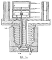
- FIG. 1 is a sectional view of a dual valve gated injection nozzle with independent actuation of the valve gates in accordance with one aspect of the present invention.
- FIG. 1A is a sectional schematic of the injection nozzle of FIG. 1 showing the machine nozzles for the two materials.
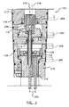
- FIG. 2 is an enlarged sectional view of the actuation system of FIG. 1.
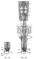
- FIG. 3A shows a first step of the operation of the system of FIG. 1.
- FIG. 3B shows a second step of the operation of the system of FIG. 1.
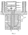
- FIG. 4 shows a second application of the nozzle system of FIG. 1.
- FIG. 5 shows a third application of the nozzle system of FIG. 1.
- System 100 includes a nozzle assembly 102 and an actuation system 104.
- a longitudinal axis 136 of nozzle assembly 102 is shown for reference.
- Nozzle assembly 102 functions, to a certain extent, similarly to known injection nozzles and includes a nozzle body 138. Melt is introduced into a first melt channel 105 and a second melt channel 107 of the nozzle body 138 via first and second manifold melt channels 106, 108 of a melt distribution manifold 122.
- the melt flowing through first melt channel 105 and first manifold melt channel106 may be the same material as the melt flowing through second melt channel 107 and second manifold melt channel108, or two different materials may be flowing through each set of channels.
- first melt and first manifold melt channels 105, 106 may be the same as the diameter of second melt and second manifold melt channels 107, 108, or the diameters of the two set of melt channels may be different. Such design considerations are heavily dependent upon the type of product to be produced by system 100 and/or the molding process being implemented.
- first manifold melt channel 106 is located closer to an outlet surface 109 of manifold 122 than second manifold melt channel 108. While not necessary for the operation of the present invention, offsetting the manifold melt channels 106, 108 allows for the later inclusion of additional melt channels or the modular addition of separate manifolds. Separate manifolds may be necessary if two different materials are used that have substantially different melt characteristics that require maintaining the melt at different temperatures.
- melt connector 121 Connecting manifold 122 to nozzle assembly 102 is a melt connector 121.
- Melt connector 121 includes a first connection melt channel 123 and a second connection melt channel 125.
- Melt connector 121 is a bushing used to connect manifold melt channels 106, 108 to nozzle melt channel 105, 107.
- Manifold melt channels 106, 108 are disposed in this embodiment towards the exterior perimeter of manifold 122.
- Nozzle melt channels 105, 107 are disposed closer to longitudinal axis 136 than manifold melt channels 106, 108.
- first connection melt channel 123 is disposed diagonally through melt connector 121 so that first connection melt channel 123 fluidly connects first manifold melt channel 106 to first nozzle melt channel 105.
- second connection melt channel 125 is disposed diagonally through melt connector 121 so that second connection melt channel 125 fluidly connects second manifold melt channel 108 to second nozzle melt channel 107.
- Heating element 124 may be coiled, embedded, clamped, and/or cast to nozzle body 138. Further, heating element 124 may be comprised of a thin or thick film heating element.
- the melt flows through first and second valve gates 114, 116 into a mold cavity (not shown). The flow of the melt through each valve gate 114, 116 is independently controlled. First valve gate 114 is open when first valve pin 110 is not seated within first valve gate 114. Similarly, second valve gate 116 is open when second valve pin 112 is not seated within second valve gate 116.
- FIG. 1A shows first valve gate 114 in the open position and second valve gate 116 in the closed position.
- first and second valve gates 114, 116 The flow of the melt through first and second valve gates 114, 116 is controlled by actuation system 104.
- Actuation system 104 is located on the opposite side of the manifold 122 as the nozzle assembly 102.
- First and second valve pins 110, 112 extend through manifold 122 into actuation system 104.
- First actuation unit 118 includes a first piston driving mechanism 204 and a first piston 208, which is slidable within a cylinder 217.
- First valve pin 110 is axially movable through a first valve pin channel 212.
- First valve pin channel 212 extends through a second actuation unit 120, manifold 122, and melt connector 121.
- First piston driving mechanism 204 may be any of several mechanisms known in the art, for example, pneumatic or hydraulic systems, bladder pistons, or cam and lever systems.
- a pneumatic driving system operates by hooking an external air source to the piston driving mechanism with valves controlled by a timing circuit which applies and releases the pressure in a repetitive timed sequence in conjunction with the application of pressure to the melt from the molding system.
- a hydraulic driving system operates in the same manner as the pneumatic system, only hydraulic fluid is substituted for air.
- first piston driving mechanism 204 may be a bladder piston, as shown and described in the copending U.S. Appl. No. 60/363891 filed on March 14, 2002 by the same assignee.
- a bladder piston is an expandable and elongated bag which shortens in length when filled with a pressurized fluid like air, water or oil.
- One end of the bladder is affixed to a valve pin such that as the bladder is pressurized it contracts in length the valve pin is unseated from the valve gate allowing the melt to flow into the mold cavity.
- depressurizing the bladder causes the bladder to increase in length, which seats the valve pin in the valve gate and stops the flow of the melt into the mold cavity.
- first piston driving mechanism 204 cycles through the sequence, first piston 208 is driven up and down. This causes first valve pin 110 to be driven downwards and upwards, thereby seating and unseating first valve pin 110 within first valve gate 114.
- a longitudinal axis 216 of actuation system 104 is slightly offset from longitudinal axis 136 of nozzle assembly 102. However, first valve pin 110 of first actuation unit 118 is centered on longitudinal axis 216.
- Second actuation unit 120 is disposed between first actuation unit 118 and manifold 122.
- Second actuation unit 120 includes a second piston driving mechanism 206 and a second piston 210, which is movable within a second cylinder 219.
- Second valve pin 112 is axially movable through a second valve pin channel 214.
- Second valve pin channel 214 extends through manifold 122 and melt connector 121.
- First valve pin channel 212 passes through second actuation unit 120 to allow first valve pin 110 to reach nozzle assembly 102 unimpeded.
- a length of second valve pin 112 and second valve pin channel 214 are offset from longitudinal axis 216 in order to provide for the disposition of first valve pin channel 212 through second actuation unit 120.
- a rod 140 is disposed on second piston 210 in order to balance the operation of second piston 210 due to the offset positioning of second valve pin 112.
- Rod 140 may also be a dowel or other similar component.
- Second piston driving mechanism 206 may be any of the various driving mechanisms as mentioned above with reference to first piston driving mechanism 204. As second piston driving mechanism 206 cycles through the sequence, second piston 210 is driven up and down. This causes second valve pin 112 to be driven downwards and upwards, thereby seating and unseating second valve pin 112 within second valve gate 116.
- first and second actuation units 118, 120 permits the minimization of a pitch 202 between the longitudinal center axis of first valve pin 110 and second valve pin 112.
- Pitch 202 may be as small as less than 7 mm.
- This tight pitch configuration of the valve pins 110, 112 makes possible the close setting of valve gates 114, 116 of nozzle assembly 102 while maintaining independent actuation of valve gates 114, 116.
- valve gates 114, 116 If a greater number of valve gates are desired with independent control from first and second valve gates 114, 116, additional actuation units can be stacked upon the existing actuation units. Additional offset valve pin channels would be provided through first and second actuation units 118, 120. Rod 140 could be eliminated as the additional valve pins would provide the necessary balancing of the piston action.
- a bladder piston actuation unit may be employed for each valve pin of a multiple valve pin arrangement which may or may not require stacking or a lateral offset of each actuation unit
- FIGS. 3A and 3B show one possible application of a tight pitch dual valve gate configuration, the overmolding of a small part.
- a mold cavity 302 is shaped to mold a dual material small part, such as a cap.
- a mold core 304 is disposed within mold cavity 302 in order to form a secondary mold cavity 306.
- Secondary mold cavity 306 is filled with a first material through second valve gate 116, which is in the open position. To prevent a second material from entering secondary mold cavity 306, first valve gate 114 is in the closed position.
- FIG. 4 shows another application of the present invention.
- the valve gated injection molding apparatus of the present invention is shown with a mold having two separate mold cavities 440, 442 of the same size and shape in close proximity.
- two similar articles of a different color or different material may be simultaneously molded. If for some reasons there is a need to mold more parts of one color than the other, the fact that two valve pins 410, 412 are independently movable allows one to inject only one kind of part for any number of cycles. Also of the two materials have different molding characteristics, such as the viscosity, the parts can be still molded by reciprocating valve pins 410, 412 at different times.
- one can either shuttle or rotate mold cavities 440, 442 to provide an overmolding solution where a second color/material is injected into each cavity.
- FIG. 5 shows another application of the present invention.
- the valve gated injection molding apparatus of the present invention is shown with a mold having two separate cavities 540, 542 of different size and shape in close proximity.
- two articles of the same or different color and/or same or different material may be simultaneously molded.
- Pressure sensors 502 are shown in the nozzle and or in the manifold that are used to control the movement of the valve pins in each melt channel, as well as the temperature of each nozzle based on the pressure readings.
Description
- This invention relates generally to injection molding and, more particularly, to a valve gated hot runner injection molding apparatus for tight pitch, single- or multi-material applications.
- JP-A-2000033634 discloses an injection molding nozzle and in particular, the nozzle body having a valve gate device. The nozzle body comprises a first melt channel and a second melt channel, which respectively communicate with two gates, which are formed in the nozzle body. The two valve pins which are opening and closing the gates are released inside the melt channel. Furthermore, the valve pins can be driven mutually independently, therefore a two-color molding or two-layer molding is possible.
- [0002a] A valve gated injection molding apparatus is well known, as shown and described in U.S. Patent No. 4,380,426. Usually a valve pin has a cylindrical or tapered front end and reciprocates between a retracted open position and a forward closed position in which the front end is seated in a gate. In some applications, the valve pin functions in the reverse direction and closes in the retracted position.
- A valve gated injection molding apparatus for coinjecting and/or sequentially injecting two different materials through a single gate with multiple valve pins into a mold cavity is also well known, as shown and described in U.S. Patent No. 5,238,378. For a greater level of control over the gating process, each individual valve pin may be independently controlled by separate actuation units.
- Also well-known in the art is a multi-cavity valve gated injection molding apparatus having a plurality of nozzles, wherein each nozzle body is provided with a plurality of equally spaced valve pin bores with a corresponding plurality of valve pins. Such an apparatus is shown and described in U.S. Patent No. 6,162,044. Each nozzle of the apparatus includes multiple valve pins, but all of the valve pins are controlled by a single actuation unit.
- Accordingly, the present invention provides an injection molding system having a single or a plurality of nozzles that include valve gate technology. Each nozzle body is provided with at least two flow channels. In some circumstances one of the flow channel is a dominant flow channel and the other is a secondary flow channel. Each flow channel is fitted with a gating element, such as a valve pin, and each valve pin is independently moved and controlled using an actuation unit, such as a fluid or gas piston. Other actuation means of the valve gating means, such as electrical or mechanical are contemplated in the current invention. Each actuation unit is located for example linearly above its respective flow channel or in some instances in a lateral position with respect to the nozzle.
- According to one aspect of this invention a primary actuation unit that controls a melt in the dominant flow channel has its valve pin centered on a longitudinal central axis of the actuation system, which is laterally offset from a longitudinal center axis of the nozzle assembly. A secondary actuation unit is located offset from the primary actuation unit with its valve pin alignment offset from the longitudinal central axis of the actuation system. The secondary actuation unit is provided with an opening so that the valve pin of the primary actuation unit can pass through the lower piston arrangement. As a result of this arrangement, the pitch from center to center of each valve pin is minimized. As such, the mold gates facing the nozzle may be arranged in a closer configuration to feed one or several mold cavities.
- The accompanying drawings, which are incorporated herein and form a part of the specification, illustrate the present invention and, together with the description, further serve to explain the principles of the invention and to enable a person skilled in the pertinent art to make and use the invention.
- FIG. 1 is a sectional view of a dual valve gated injection nozzle with independent actuation of the valve gates in accordance with one aspect of the present invention.
- FIG. 1A is a sectional schematic of the injection nozzle of FIG. 1 showing the machine nozzles for the two materials.
- FIG. 2 is an enlarged sectional view of the actuation system of FIG. 1.
- FIG. 3A shows a first step of the operation of the system of FIG. 1.
- FIG. 3B shows a second step of the operation of the system of FIG. 1.
- FIG. 4 shows a second application of the nozzle system of FIG. 1.
- FIG. 5 shows a third application of the nozzle system of FIG. 1.
- The present invention is now described with reference to the figures, where like reference numbers indicate identical or functionally similar elements.
- Referring now to FIG. 1, a valve gated
injection molding system 100 is shown.System 100 includes anozzle assembly 102 and anactuation system 104. Alongitudinal axis 136 ofnozzle assembly 102 is shown for reference. -
Nozzle assembly 102 functions, to a certain extent, similarly to known injection nozzles and includes anozzle body 138. Melt is introduced into afirst melt channel 105 and asecond melt channel 107 of thenozzle body 138 via first and secondmanifold melt channels melt distribution manifold 122. The melt flowing throughfirst melt channel 105 and first manifold melt channel106 may be the same material as the melt flowing throughsecond melt channel 107 and second manifold melt channel108, or two different materials may be flowing through each set of channels. Also, the diameter of first melt and firstmanifold melt channels manifold melt channels system 100 and/or the molding process being implemented. - As shown in FIG. 1, first
manifold melt channel 106 is located closer to anoutlet surface 109 ofmanifold 122 than secondmanifold melt channel 108. While not necessary for the operation of the present invention, offsetting themanifold melt channels - Connecting
manifold 122 tonozzle assembly 102 is amelt connector 121.Melt connector 121 includes a firstconnection melt channel 123 and a secondconnection melt channel 125.Melt connector 121 is a bushing used to connectmanifold melt channels nozzle melt channel melt channels manifold 122.Nozzle melt channels longitudinal axis 136 thanmanifold melt channels connection melt channel 123 is disposed diagonally throughmelt connector 121 so that firstconnection melt channel 123 fluidly connects firstmanifold melt channel 106 to firstnozzle melt channel 105. Similarly, secondconnection melt channel 125 is disposed diagonally throughmelt connector 121 so that secondconnection melt channel 125 fluidly connects secondmanifold melt channel 108 to secondnozzle melt channel 107. - As the melt flows through the first and
second melt channels nozzle body 138, the temperature of the melt is maintained byheating element 124. Heatingelement 124 may be coiled, embedded, clamped, and/or cast tonozzle body 138. Further,heating element 124 may be comprised of a thin or thick film heating element. The melt flows through first andsecond valve gates valve gate First valve gate 114 is open whenfirst valve pin 110 is not seated withinfirst valve gate 114. Similarly,second valve gate 116 is open whensecond valve pin 112 is not seated withinsecond valve gate 116. FIG. 1A showsfirst valve gate 114 in the open position andsecond valve gate 116 in the closed position. - The flow of the melt through first and
second valve gates actuation system 104.Actuation system 104 is located on the opposite side of the manifold 122 as thenozzle assembly 102. First and second valve pins 110, 112 extend throughmanifold 122 intoactuation system 104. - With reference now to FIG. 2, movement of the
first valve pin 110 is controlled by afirst actuation unit 118.First actuation unit 118 includes a firstpiston driving mechanism 204 and afirst piston 208, which is slidable within acylinder 217.First valve pin 110 is axially movable through a firstvalve pin channel 212. Firstvalve pin channel 212 extends through asecond actuation unit 120, manifold 122, and meltconnector 121. - First
piston driving mechanism 204 may be any of several mechanisms known in the art, for example, pneumatic or hydraulic systems, bladder pistons, or cam and lever systems. A pneumatic driving system operates by hooking an external air source to the piston driving mechanism with valves controlled by a timing circuit which applies and releases the pressure in a repetitive timed sequence in conjunction with the application of pressure to the melt from the molding system. A hydraulic driving system operates in the same manner as the pneumatic system, only hydraulic fluid is substituted for air. - In another embodiment, first
piston driving mechanism 204 may be a bladder piston, as shown and described in the copending U.S. Appl. No. 60/363891 filed on March 14, 2002 by the same assignee. A bladder piston is an expandable and elongated bag which shortens in length when filled with a pressurized fluid like air, water or oil. One end of the bladder is affixed to a valve pin such that as the bladder is pressurized it contracts in length the valve pin is unseated from the valve gate allowing the melt to flow into the mold cavity. Similarly, depressurizing the bladder causes the bladder to increase in length, which seats the valve pin in the valve gate and stops the flow of the melt into the mold cavity. - As first
piston driving mechanism 204 cycles through the sequence,first piston 208 is driven up and down. This causesfirst valve pin 110 to be driven downwards and upwards, thereby seating and unseatingfirst valve pin 110 withinfirst valve gate 114. - A
longitudinal axis 216 ofactuation system 104 is slightly offset fromlongitudinal axis 136 ofnozzle assembly 102. However,first valve pin 110 offirst actuation unit 118 is centered onlongitudinal axis 216. - In order to minimize the space required to control movement of the valve pins 110, 112 independently, the
second actuation unit 120 is disposed betweenfirst actuation unit 118 andmanifold 122.Second actuation unit 120 includes a secondpiston driving mechanism 206 and asecond piston 210, which is movable within asecond cylinder 219.Second valve pin 112 is axially movable through a secondvalve pin channel 214. Secondvalve pin channel 214 extends throughmanifold 122 and meltconnector 121. - First
valve pin channel 212 passes throughsecond actuation unit 120 to allowfirst valve pin 110 to reachnozzle assembly 102 unimpeded. A length ofsecond valve pin 112 and secondvalve pin channel 214 are offset fromlongitudinal axis 216 in order to provide for the disposition of firstvalve pin channel 212 throughsecond actuation unit 120. As shown in FIG. 1A, arod 140 is disposed onsecond piston 210 in order to balance the operation ofsecond piston 210 due to the offset positioning ofsecond valve pin 112.Rod 140 may also be a dowel or other similar component. - Second
piston driving mechanism 206 may be any of the various driving mechanisms as mentioned above with reference to firstpiston driving mechanism 204. As secondpiston driving mechanism 206 cycles through the sequence,second piston 210 is driven up and down. This causessecond valve pin 112 to be driven downwards and upwards, thereby seating and unseatingsecond valve pin 112 withinsecond valve gate 116. - This arrangement of first and
second actuation units pitch 202 between the longitudinal center axis offirst valve pin 110 andsecond valve pin 112.Pitch 202 may be as small as less than 7 mm. This tight pitch configuration of the valve pins 110, 112 makes possible the close setting ofvalve gates nozzle assembly 102 while maintaining independent actuation ofvalve gates - If a greater number of valve gates are desired with independent control from first and
second valve gates second actuation units Rod 140 could be eliminated as the additional valve pins would provide the necessary balancing of the piston action. - A bladder piston actuation unit may be employed for each valve pin of a multiple valve pin arrangement which may or may not require stacking or a lateral offset of each actuation unit
- FIGS. 3A and 3B show one possible application of a tight pitch dual valve gate configuration, the overmolding of a small part. A
mold cavity 302 is shaped to mold a dual material small part, such as a cap. Amold core 304 is disposed withinmold cavity 302 in order to form asecondary mold cavity 306.Secondary mold cavity 306 is filled with a first material throughsecond valve gate 116, which is in the open position. To prevent a second material from enteringsecondary mold cavity 306,first valve gate 114 is in the closed position. - FIG. 3B shows the second step of the overmolding process in which a
mold core 304 has been moved axially away from thevalve gates mold cavity 302 throughfirst valve gate 114, which is in an open configuration to permit the flow of the second material.Second valve gate 116 is in the closed configuration to prevent further injection of the first material in tomold cavity 302. The second material covers a first molded material piece 306a to form a single dual material cap. - FIG. 4 shows another application of the present invention. The valve gated injection molding apparatus of the present invention is shown with a mold having two
separate mold cavities valve pins mold cavities - FIG. 5 shows another application of the present invention. The valve gated injection molding apparatus of the present invention is shown with a mold having two
separate cavities Pressure sensors 502 are shown in the nozzle and or in the manifold that are used to control the movement of the valve pins in each melt channel, as well as the temperature of each nozzle based on the pressure readings. - While various embodiments of the present invention have been described above, it should be understood that they have been presented by way of example only, and not limitation. It will be apparent to persons skilled in the relevant art that various changes in form and detail can be made therein without departing from the spirit and scope of the invention. Thus, the breadth and scope of the present invention should not be limited by any of the above-described exemplary embodiments, but should be defined only in accordance with the following claims and their equivalents.
Claims (7)
- An injection nozzle comprising:a nozzle body (102) having a first nozzle melt channel (105) and a second nozzle melt channel (107);a first valve gating element (110) for selectively opening a first mould gate (114);a second valve gating element (112) for selectively opening a second mould gate (116);a first actuation mechanism (118) coupled to the first valve gating element (110);a second actuation mechanism (120) coupled to the second valve gating element (112);means to drive independently the first (118) and second (120) actuation mechanisms to displace the first and second valve gating mechanisms relative to each other,characterized in that
the second actuation mechanism (120) is positioned between the first actuation mechanism (118) and the nozzle body (102) and is configured to allow the first valve gating element (110) to pass therethrough unimpeded. - An injection molding apparatus comprising:the injection nozzle according to claim 1,a manifold (122) having a first manifold melt channel (106) for receiving a first melt stream of moldable material and a second manifold channel (108) for receiving a second melt stream of moldable material.
- The injection molding apparatus according to claim 2, further comprising a melt channel connector (121) provided between the manifold (122) and the nozzle, the melt channel connector having a first connecting melt channel (106) and a second connecting melt channel (108),
wherein the first connecting melt channel is in fluid communication with the first manifold melt channel and the first nozzle melt channel (105), and the second connecting channel is in fluid communication with the second manifold melt channel and the second nozzle melt channel (107). - The injection molding apparatus according to claim 2, wherein the melt channel connector (121) is a bushing for receiving the first valve gating element (110) and the second valve gating element (112).
- The injection molding apparatus according to claim 2, wherein the first valve gating element (110) extends through the second actuation mechanism (120).
- The injection molding apparatus according to claim 2, further comprising a bushing surrounding the first valve gating element (110), the bushing being slidable through the second actuation mechanism (120).
- The injection molding apparatus according to claim 2, wherein the first actuation mechanism (118) includes a first piston coupled to the first valve gating element (110) and the second actuation mechanism (120) includes a second piston coupled to the second valve gating element (112).
Applications Claiming Priority (2)
| Application Number | Priority Date | Filing Date | Title |
|---|---|---|---|
| US42358502P | 2002-11-05 | 2002-11-05 | |
| US423585P | 2002-11-05 |
Publications (2)
| Publication Number | Publication Date |
|---|---|
| EP1418034A1 EP1418034A1 (en) | 2004-05-12 |
| EP1418034B1 true EP1418034B1 (en) | 2007-02-21 |
Family
ID=32108166
Family Applications (1)
| Application Number | Title | Priority Date | Filing Date |
|---|---|---|---|
| EP03025448A Expired - Lifetime EP1418034B1 (en) | 2002-11-05 | 2003-11-05 | Tight pitch nozzle with individual valve gate control |
Country Status (6)
| Country | Link |
|---|---|
| US (1) | US7192270B2 (en) |
| EP (1) | EP1418034B1 (en) |
| JP (1) | JP4489407B2 (en) |
| CN (1) | CN100408303C (en) |
| CA (1) | CA2448129C (en) |
| DE (1) | DE60311940T2 (en) |
Families Citing this family (15)
| Publication number | Priority date | Publication date | Assignee | Title |
|---|---|---|---|---|
| US7648669B2 (en) * | 2004-11-30 | 2010-01-19 | Bemis Manufacturing Company | Injection-molding system and method |
| CA2540532A1 (en) * | 2005-04-25 | 2006-10-25 | Sulzer Chemtech Ag | An apparatus with a needle shut-off nozzle for an injection moulding machine |
| CN101088738B (en) * | 2006-06-16 | 2012-11-14 | 马斯特模具(2007)有限公司 | Open loop pressure control for injection molding |
| US7527490B2 (en) * | 2006-10-13 | 2009-05-05 | Mold-Masters (2007) Limited | Coinjection molding apparatus and related hot-runner nozzle |
| US7731489B2 (en) * | 2006-12-21 | 2010-06-08 | Mold-Masters (2007) Limited | Valve for co-injection molding apparatus |
| US7658606B2 (en) * | 2006-12-22 | 2010-02-09 | Mold-Masters (2007) Limited | Edge gated injection molding apparatus |
| GB201021271D0 (en) * | 2010-12-15 | 2011-01-26 | Pilkington Group Ltd | Process and apparatus for moulding a glazing profile onto a glazing |
| JP6035330B2 (en) * | 2011-05-20 | 2016-11-30 | アイエムフラックス インコーポレイテッド | Non-natural equilibrium supply system for injection molding equipment |
| CN102529024B (en) * | 2012-01-09 | 2014-04-30 | 东莞市凯昶德电子科技股份有限公司 | Self-locking nozzle for injection molding machine |
| JP5859875B2 (en) * | 2012-02-27 | 2016-02-16 | フィーサ株式会社 | Injection device for injection molding equipment |
| WO2015107178A1 (en) * | 2014-01-16 | 2015-07-23 | Otto Männer Innovation GmbH | Side gating hot runner nozzle and associated floating manifold seals |
| KR101936986B1 (en) * | 2015-01-28 | 2019-03-28 | 인글라스 에스피에이 | System and method for injection moulding of plastic materials |
| CN105500633B (en) * | 2016-01-27 | 2018-02-13 | 上海缔翊模具有限公司 | Multiple material mixed injection molding head and multiple material mixed injection molding mould |
| EP3651965B1 (en) | 2017-07-14 | 2022-03-02 | Otto Männer GmbH | Injection molding device |
| KR102037356B1 (en) * | 2018-05-28 | 2019-10-28 | 허남욱 | Double piston Apparatus for operating a valve pin in a valve operated hot runner injection mold |
Citations (2)
| Publication number | Priority date | Publication date | Assignee | Title |
|---|---|---|---|---|
| JPH06170888A (en) * | 1992-12-03 | 1994-06-21 | Toyo Mach & Metal Co Ltd | Control of composite molding machine |
| US6332767B1 (en) * | 1983-04-13 | 2001-12-25 | Pechiney Emballage Flexible Europe | Apparatus for injection molding multi-layer articles |
Family Cites Families (30)
| Publication number | Priority date | Publication date | Assignee | Title |
|---|---|---|---|---|
| US2418856A (en) * | 1939-06-20 | 1947-04-15 | French Oil Mill Machinery | Method of and apparatus for injection molding |
| CH566207A5 (en) * | 1972-12-07 | 1975-09-15 | Siemag Siegener Masch Bau | |
| DE2346135C2 (en) * | 1973-09-13 | 1982-11-04 | Battenfeld Maschinenfabriken Gmbh, 5882 Meinerzhagen | Method and device for the injection molding of plastic moldings which consist of a filling layer made of a thermoplastic material and a covering layer made of another thermoplastic material which encloses it |
| US4279582A (en) * | 1979-04-02 | 1981-07-21 | Incoe Corporation | Method and apparatus for individual control of injection mold shut-off bushings |
| CA1174820A (en) * | 1982-02-24 | 1984-09-25 | William J. Wiles | Injection molding valve pin direct pneumatic actuator |
| US4803031A (en) * | 1982-06-03 | 1989-02-07 | Anchor Hocking Corporation | Method and apparatus for molding a closure cap |
| DE3245571C2 (en) | 1982-12-09 | 1985-04-11 | Männer, Otto, 7836 Bahlingen | Valve gate nozzle for injection molds |
| US4657496A (en) * | 1984-06-04 | 1987-04-14 | Gifu Husky Co., Ltd. | Hot-runner mold for injection molding |
| DE3733363A1 (en) | 1987-10-02 | 1989-04-13 | Horst Prinz | Hot-runner needle-valve nozzle for processing thermoplastic materials |
| US5078589A (en) * | 1990-06-15 | 1992-01-07 | Osuna Diaz J M | Multicavity injection molding apparatus having precision adjustment and shut off of injection flow to individual mold cavities |
| US5223275A (en) * | 1990-10-12 | 1993-06-29 | Gellert Jobst U | Multi-cavity injection moulding system |
| WO1992013700A1 (en) * | 1991-02-12 | 1992-08-20 | Seiki Corporation | Improved hot runner mold arrangement and use thereof |
| DE4206318C2 (en) * | 1992-02-29 | 1994-06-16 | Otto Maenner | Multiple needle valve nozzle for injection molds |
| DE4206319C2 (en) * | 1992-02-29 | 1994-04-28 | Otto Maenner | Needle valve with piston drive |
| CA2068543C (en) * | 1992-05-11 | 1999-11-09 | Jobst Ulrich Gellert | Coinjection molding apparatus having rotary axial actuating mechanism |
| US5372496A (en) * | 1993-02-18 | 1994-12-13 | Taniyama; Yoshihiko | Ejector valve plastic molding apparatus |
| EP0614744B1 (en) * | 1993-02-25 | 1998-11-04 | Sony Electronics Inc. | Molding devices |
| DE4324275C2 (en) * | 1993-07-20 | 1996-05-02 | Incoe Corp | Pneumatic control device for hot runner needle valves for injection molding tools |
| US5650178A (en) * | 1994-11-23 | 1997-07-22 | Bemis Manufacturing Company | Co-injection manifold for injection molding |
| CA2175634C (en) * | 1996-05-02 | 2007-08-21 | Klaus Bauer | Injection molding valve member with head and neck portions |
| US5935621A (en) * | 1997-01-24 | 1999-08-10 | Mold-Masters Limited | Injection molding apparatus having a cooled core |
| US5972258A (en) * | 1997-10-20 | 1999-10-26 | Husky Injection Molding Systems Ltd. | Method of using a multiple gating nozzle |
| CA2219235C (en) * | 1997-10-23 | 2006-12-12 | Mold-Masters Limited | Five layer injection molding apparatus having four position valve member actuating mechanism |
| JP3225914B2 (en) | 1998-02-13 | 2001-11-05 | 三菱マテリアル株式会社 | Valve gate device and injection mold provided with this valve gate device |
| JP2000025072A (en) | 1998-07-13 | 2000-01-25 | Mitsubishi Materials Corp | Pin driving mechanism for valve gate apparatus in mold for injection molding |
| JP4062382B2 (en) | 1998-07-16 | 2008-03-19 | 株式会社Ipm | Valve gate device |
| CA2264224A1 (en) * | 1999-02-26 | 2000-08-26 | Denis Babin | Multi-cavity injection molding apparatus splitting melt near nozzle front |
| JP4024436B2 (en) | 1999-10-13 | 2007-12-19 | 柳道実業株式会社 | Resin injection device for injection molding machine that operates many valve pins with one piston |
| JP2002036310A (en) | 2000-07-25 | 2002-02-05 | Mitsubishi Materials Corp | Method for molding member for microrelay and valve gate device used for the same |
| US7175419B2 (en) * | 2002-12-03 | 2007-02-13 | Mold-Masters Limited | Hot runner co-injection nozzle |
-
2003
- 2003-11-05 CN CNB2003101198153A patent/CN100408303C/en not_active Expired - Lifetime
- 2003-11-05 US US10/700,521 patent/US7192270B2/en active Active
- 2003-11-05 JP JP2003375910A patent/JP4489407B2/en not_active Expired - Lifetime
- 2003-11-05 CA CA2448129A patent/CA2448129C/en not_active Expired - Lifetime
- 2003-11-05 DE DE60311940T patent/DE60311940T2/en not_active Expired - Lifetime
- 2003-11-05 EP EP03025448A patent/EP1418034B1/en not_active Expired - Lifetime
Patent Citations (2)
| Publication number | Priority date | Publication date | Assignee | Title |
|---|---|---|---|---|
| US6332767B1 (en) * | 1983-04-13 | 2001-12-25 | Pechiney Emballage Flexible Europe | Apparatus for injection molding multi-layer articles |
| JPH06170888A (en) * | 1992-12-03 | 1994-06-21 | Toyo Mach & Metal Co Ltd | Control of composite molding machine |
Also Published As
| Publication number | Publication date |
|---|---|
| CA2448129C (en) | 2012-01-03 |
| EP1418034A1 (en) | 2004-05-12 |
| JP2004155196A (en) | 2004-06-03 |
| US20040091569A1 (en) | 2004-05-13 |
| CN100408303C (en) | 2008-08-06 |
| DE60311940D1 (en) | 2007-04-05 |
| CN1526538A (en) | 2004-09-08 |
| JP4489407B2 (en) | 2010-06-23 |
| DE60311940T2 (en) | 2007-06-14 |
| CA2448129A1 (en) | 2004-05-05 |
| US7192270B2 (en) | 2007-03-20 |
Similar Documents
| Publication | Publication Date | Title |
|---|---|---|
| EP1418034B1 (en) | Tight pitch nozzle with individual valve gate control | |
| US6575731B1 (en) | Apparatus for distributing melt in a multi-level stack mold | |
| US7175420B2 (en) | Valve gated injection molding system with independent flow control | |
| EP0614744B1 (en) | Molding devices | |
| JP3258282B2 (en) | Sprue gate type 5-layer injection molding machine | |
| CA2878559A1 (en) | Coinjection molding apparatus and related hot-runner nozzle | |
| KR100822124B1 (en) | Removable injection molding shooting pot assembly with check valve | |
| US6348171B1 (en) | Drool control apparatus and method | |
| EP1993801B1 (en) | Co-injection nozzle assembly | |
| CN1246089A (en) | Fluid assist valve-gate bushing with concentric pin members | |
| CA2597843A1 (en) | Nozzle and apparatus for injection molding | |
| EP1765567B1 (en) | Apparatus for sealing injection unit and sprue | |
| CN102189635A (en) | Multi-axis injection molding apparatus | |
| CN108454011A (en) | Hot flow path injection nozzle and actuator for injection-molding apparatus | |
| JP4024436B2 (en) | Resin injection device for injection molding machine that operates many valve pins with one piston | |
| US20020028266A1 (en) | Valve gate assembly for injection molding | |
| EP1658169B1 (en) | Multi-position valve pin for an injection molding apparatus and corresponding method | |
| JPH066900Y2 (en) | Injection molding nozzle | |
| CN111958927A (en) | Injection molding apparatus with hot runner | |
| WO2002036323A1 (en) | Co-injection valve-gate bushing with separate material flow paths | |
| MXPA98008713A (en) | Injection molding apparatus that has transfer bushings of bath fused between multip | |
| JP2003340881A (en) | Mold device for molding |
Legal Events
| Date | Code | Title | Description |
|---|---|---|---|
| PUAI | Public reference made under article 153(3) epc to a published international application that has entered the european phase |
Free format text: ORIGINAL CODE: 0009012 |
|
| AK | Designated contracting states |
Kind code of ref document: A1 Designated state(s): AT BE BG CH CY CZ DE DK EE ES FI FR GB GR HU IE IT LI LU MC NL PT RO SE SI SK TR |
|
| AX | Request for extension of the european patent |
Extension state: AL LT LV MK |
|
| 17P | Request for examination filed |
Effective date: 20041112 |
|
| AKX | Designation fees paid |
Designated state(s): DE FR IT |
|
| 17Q | First examination report despatched |
Effective date: 20050706 |
|
| RBV | Designated contracting states (corrected) |
Designated state(s): DE FR IT |
|
| GRAP | Despatch of communication of intention to grant a patent |
Free format text: ORIGINAL CODE: EPIDOSNIGR1 |
|
| 17Q | First examination report despatched |
Effective date: 20050706 |
|
| GRAS | Grant fee paid |
Free format text: ORIGINAL CODE: EPIDOSNIGR3 |
|
| GRAA | (expected) grant |
Free format text: ORIGINAL CODE: 0009210 |
|
| AK | Designated contracting states |
Kind code of ref document: B1 Designated state(s): DE FR IT |
|
| REF | Corresponds to: |
Ref document number: 60311940 Country of ref document: DE Date of ref document: 20070405 Kind code of ref document: P |
|
| ET | Fr: translation filed | ||
| PLBE | No opposition filed within time limit |
Free format text: ORIGINAL CODE: 0009261 |
|
| STAA | Information on the status of an ep patent application or granted ep patent |
Free format text: STATUS: NO OPPOSITION FILED WITHIN TIME LIMIT |
|
| 26N | No opposition filed |
Effective date: 20071122 |
|
| REG | Reference to a national code |
Ref country code: FR Ref legal event code: TP |
|
| REG | Reference to a national code |
Ref country code: FR Ref legal event code: PLFP Year of fee payment: 13 |
|
| REG | Reference to a national code |
Ref country code: FR Ref legal event code: PLFP Year of fee payment: 14 |
|
| REG | Reference to a national code |
Ref country code: FR Ref legal event code: PLFP Year of fee payment: 15 |
|
| REG | Reference to a national code |
Ref country code: FR Ref legal event code: PLFP Year of fee payment: 16 |
|
| PGFP | Annual fee paid to national office [announced via postgrant information from national office to epo] |
Ref country code: FR Payment date: 20221021 Year of fee payment: 20 |
|
| PGFP | Annual fee paid to national office [announced via postgrant information from national office to epo] |
Ref country code: IT Payment date: 20221020 Year of fee payment: 20 Ref country code: DE Payment date: 20221020 Year of fee payment: 20 |
|
| REG | Reference to a national code |
Ref country code: DE Ref legal event code: R071 Ref document number: 60311940 Country of ref document: DE |