EP1424941B1 - Customizable split stem stethoscope - Google Patents
Customizable split stem stethoscope Download PDFInfo
- Publication number
- EP1424941B1 EP1424941B1 EP02768715A EP02768715A EP1424941B1 EP 1424941 B1 EP1424941 B1 EP 1424941B1 EP 02768715 A EP02768715 A EP 02768715A EP 02768715 A EP02768715 A EP 02768715A EP 1424941 B1 EP1424941 B1 EP 1424941B1
- Authority
- EP
- European Patent Office
- Prior art keywords
- chestpiece
- tubing
- ear
- stethoscope
- length
- Prior art date
- Legal status (The legal status is an assumption and is not a legal conclusion. Google has not performed a legal analysis and makes no representation as to the accuracy of the status listed.)
- Expired - Lifetime
Links
Images


Classifications
-
- A—HUMAN NECESSITIES
- A61—MEDICAL OR VETERINARY SCIENCE; HYGIENE
- A61B—DIAGNOSIS; SURGERY; IDENTIFICATION
- A61B7/00—Instruments for auscultation
- A61B7/02—Stethoscopes
Definitions
- the invention relates generally to stethoscopes and, more particularly to the way stethoscopes are prepared for their intended user.
- Stethoscopes have long been used by health care professionals to monitor acoustic communication.
- stethoscopes have been comprised of a microphone or chestpiece, a sound transmission mechanism and an earpiece assembly.
- the chestpiece is adapted to be placed near or against the skin of a patient for gathering the auscultatory sounds.
- the sound transmission mechanism transmits the gathered sound to an earpiece, or a pair of earpieces called a binaural, where the physician or other health professional may monitor the sound.
- stethoscopes have utilized electronics for at least part of the sound processing path.
- the auditory sound is picked up by a microphone usually located in a detection device which is similar to the chestpiece of a conventional acoustic stethoscope in external appearance.
- the electrical signal from the microphone is then processed electronically and is coupled to a speaker, or speakers, where the electrical signal is converted back into an auditory sound for reception by the health care professional.
- other electronic analysis or display of the auscultatory sound may be performed by the signal processor, in addition to the usual conversion back into an auditory sound.
- Stethescopes commonly include a tubing assembly having twin, smooth-walled sound pathways extending from the chestpiece to the ear tips. Preferably these pathways are free of sound leakage and each pathway has a constant diameter along its entire length.
- preferred stethoscopes contain a pair of passageways formed in flexible tubing that is molded side-by-side in a one-piece construction for a major portion of the distance between chestpiece and ear tubes. In such constructions, each pathway is conveniently a lumen within a dip-molded polymeric tubing assembly, the two lumens being separated by a wall. Stethoscopes made in this way have enjoyed commercial success as the Littmann TM Cardiology and Master Cardiology stethoscopes, available from 3M Company of St. Paul, Minnesota.
- the final product of the tubing assembly intended for connection to the chest piece is molded in predetermined lengths of tubing assembly.
- Each length that is to be offered to a customer must be inventoried separately, both by the manufacturer and the distributor. If a wide range of colors or other custom features are to be offered even more must be inventoried.
- the present art lacks a way of providing the acoustic benefits of a twin lumen construction while at the same time minimizing inventory.
- the present invention solves this problem by providing a specialized chest piece that will adapt to a dual lumen binaural, without that binaural having a molded-in connection. This allows binaurals for stethoscopes to be manufactured in a generic fashion at the maximum desirable length on the expectation that they can be cut down to the length the customer desires at the time of assembly.
- the present invention provides a stethoscope having at least one pair of elongated ear tubes and a chestpiece in acoustic communication with the elongated ear tubes.
- the chestpiece is in acoustic communication through an adapter comprising a hollow stem, with this stem having a slot therein.
- a tubing assembly acoustically connects the at least one chestpiece to the ear tubes.
- the tubing comprises a wall that defines separate twin passages extending throughout the length of the tubing and that is adapted for connecting to the slot of the hollow stem of the chestpiece thereby forming twin air columns extending between the at least one chestpiece and the upper ends of the ear tubes.
- the present invention overcomes many of the drawbacks associated with the prior art methods by enabling the manufacturing of the binaurals in a generic (i.e. uniform) fashion at the maximum desirable length with the expectation that they can be cut down to the length determined by the customer.
- the stethoscope 10 includes a binaural 11 having a pair of ear tubes 12 secured together by a prestressed leaf spring 14 optionally enclosed in tubing 16.
- a conventional chestpiece 18 is attached to ear tubes 12 by elongated flexible tubing 20 which contains dual lumens 22 to serve as sound-conveying air passages and which run side-by-side within a common structure of flexible plastic tubing such as polyvinyl chloride for a major portion of the distance between chestpiece 18 and ear tubes 12.
- the two lumens 22 are separated by a wall 23.
- tubing 20 In the lower end of tubing 20 which attaches to chestpiece 18, lumens 22 merge into a single molded in connection 25 adapted to be coupled to a stem 24 of an appropriate chestpiece 18.
- the stem 24 serves as an adapter to make a connection between the binaural 11 and the rest of the chestpiece 18.
- the upper end of tubing 20 bifurcates into coupling arms 26, each of which attaches to one of the ear tubes 12.
- the air passages 22 are continued as air passages 28 in the coupling arms which are in turn continued as air passages 30 in the ear tubes 12.
- the binaural ear tubes 12 have upper ends suitably curved toward each other to allow insertion into the ears of the wearer. Ear tips 34 are attached to the upper ends of ear tubes 12 to provide cushioning for the ears and also to insulate the ears against outside sounds.
- the lower end portions 35 of ear tubes 12 extend into the respective coupling arms 26 of flexible tubing 20, and an air-tight junction is formed between air passages 28 of coupling arms 26 and air passages 30 of the respective ear tubes to which they are joined.
- a bushing 42 may be provided to help attach with the leaf spring 14 to the lower end portions 35 of ear tubes 12.
- a stethoscope having a single leaf spring is illustrated, it is also contemplated that a double leaf spring arrangement similar to that illustrated in U.S. Pat. Nos. 3,168,161 or 3,504,760 may be used. Additional construction details and methods may be found in coassigned U.S. Patent 4,200,169 to MacDonald et al.
- Molded-in connection 25 is adapted to receive the stem 24, and this cannot be modified after fabrication. If one were to cut flexible tubing 20 to a shorter length, wall 23 would prevent the stem 24 from engaging the flexible tubing 20.
- an exemplary stethoscope according to the present invention is illustrated in a view similar to that of Fig. 1.
- the binaural 11a does not have a molded-in connection 25; the wall 23 extends as far as the end of the flexible tubing 20a and is received in a slot 44 in stem 24a.
- This arrangement offers the advantage that the flexible tubing 20a can be manufactured in one length in each color, specifically in the longest length that consumers prefer. When a customer orders a shorter length, that one manufactured size can be cut down with a knife to the preferred length and stem 24a provided by the present invention will receive it securely.
- the flexible tubing 20a may be shortened with household tools.
- the chestpiece 18a may be any appropriate chestpiece having good acoustical quality.
- the chestpiece 18a may be a conventional type, having e.g. one diaphragm-type microphone and one bell-type microphone.
- the diaphragm is regarded as better for picking up higher frequency sounds and the bell is preferred for the lower frequencies.
- the bell is in essence an open cup which is placed over the desired spot on the body and the diaphragm is similar but with a membrane or diaphragm stretched over the mouth of the cup.
- the detailed design of chestpieces has been the subject of much variation, for the purpose of maximizing the useful audio information that can be collected.
- Various shapes and configurations are known. Combination chestpieces which can be used in either mode are common (U.S. Pat. No. 3,951,230) and are preferred in the present invention.
- the microphone on chestpiece 18a may be at the so-called tunable type, which has a diaphragm supported by a flexible surround.
- the diaphragm may be held lightly against the patient's body in order to emphasize lower frequency sounds. If the diaphragm is pressed sufficiently firmly against the patient's body, it will contact an annular ring mounted behind the diaphragm which will cause the acoustical characteristics of microphone to change, specifically to attenuate lower sound frequencies. Additional discussion of this phenomenon can be found in coassigned U.S. Patent 4,440,258 to Packard.
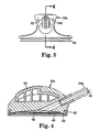
- FIG. 3 A chestpiece adapted for use with a tunable microphone is illustrated in Fig. 3.
- This chestpiece 18b includes a stem 24b according to the present invention.
- the chestpiece 18b includes an annular flange 40 to support a flexible surround as will be described with more particularity in connection with Fig. 4.
- the stem 24b may have barbs 42 to assist in retaining binaural 11a.
- other expedients such as e.g., knurling, adhesives, an external ferrule or simple friction assist in retaining binaural 11a.
- the tunable microphone 46 includes a diaphragm 48 supported by a flexible surround 50 held onto the tunable microphone 46 by a rim 52.
- the illustrated embodiment includes a grip 54 injection molded from polymeric material to provide ease of handling.
- stem 24b is seen in isolation.
- a knurled region 56 may be provided to assist in retaining the stem 24b within the remainder of the chestpiece 18b.
- ear tips are considered usable with the present invention. Relatively hard, but low-friction, polymeric ear tips fabricated from e.g. Delrin TM are preferred by some users. Softer ear tips which conform to the outer ear of the wearer are also popular. The conformable ear tips disclosed in coassigned U.S. patent 4,913,259 are considered preferred. Custom indicia may be added to e.g. the chestpiece 18b by such methods as stamping, laser marking, and chemical etching after masking.
Abstract
Description
- The invention relates generally to stethoscopes and, more particularly to the way stethoscopes are prepared for their intended user.
- Stethoscopes have long been used by health care professionals to monitor acoustic communication. Typically stethoscopes have been comprised of a microphone or chestpiece, a sound transmission mechanism and an earpiece assembly. The chestpiece is adapted to be placed near or against the skin of a patient for gathering the auscultatory sounds. The sound transmission mechanism transmits the gathered sound to an earpiece, or a pair of earpieces called a binaural, where the physician or other health professional may monitor the sound.
- Recently, some stethoscopes have utilized electronics for at least part of the sound processing path. In most of these devices, the auditory sound is picked up by a microphone usually located in a detection device which is similar to the chestpiece of a conventional acoustic stethoscope in external appearance. The electrical signal from the microphone is then processed electronically and is coupled to a speaker, or speakers, where the electrical signal is converted back into an auditory sound for reception by the health care professional. Of course, other electronic analysis or display of the auscultatory sound may be performed by the signal processor, in addition to the usual conversion back into an auditory sound.
- Stethescopes commonly include a tubing assembly having twin, smooth-walled sound pathways extending from the chestpiece to the ear tips. Preferably these pathways are free of sound leakage and each pathway has a constant diameter along its entire length. Often preferred stethoscopes contain a pair of passageways formed in flexible tubing that is molded side-by-side in a one-piece construction for a major portion of the distance between chestpiece and ear tubes. In such constructions, each pathway is conveniently a lumen within a dip-molded polymeric tubing assembly, the two lumens being separated by a wall. Stethoscopes made in this way have enjoyed commercial success as the Littmann ™ Cardiology and Master Cardiology stethoscopes, available from 3M Company of St. Paul, Minnesota.
- Typically in such constructions, the final product of the tubing assembly intended for connection to the chest piece is molded in predetermined lengths of tubing assembly. Each length that is to be offered to a customer must be inventoried separately, both by the manufacturer and the distributor. If a wide range of colors or other custom features are to be offered even more must be inventoried. The present art lacks a way of providing the acoustic benefits of a twin lumen construction while at the same time minimizing inventory.
- The present invention solves this problem by providing a specialized chest piece that will adapt to a dual lumen binaural, without that binaural having a molded-in connection. This allows binaurals for stethoscopes to be manufactured in a generic fashion at the maximum desirable length on the expectation that they can be cut down to the length the customer desires at the time of assembly.
- More particularly, in one aspect the present invention provides a stethoscope having at least one pair of elongated ear tubes and a chestpiece in acoustic communication with the elongated ear tubes. The chestpiece is in acoustic communication through an adapter comprising a hollow stem, with this stem having a slot therein. A tubing assembly acoustically connects the at least one chestpiece to the ear tubes. The tubing comprises a wall that defines separate twin passages extending throughout the length of the tubing and that is adapted for connecting to the slot of the hollow stem of the chestpiece thereby forming twin air columns extending between the at least one chestpiece and the upper ends of the ear tubes.
- The present invention overcomes many of the drawbacks associated with the prior art methods by enabling the manufacturing of the binaurals in a generic (i.e. uniform) fashion at the maximum desirable length with the expectation that they can be cut down to the length determined by the customer. These and other objects of the present invention will be apparent in view of the following description of the invention and the preferred embodiments.
- In the several figures of the attached drawing, like parts bear like reference numerals, and:
- Fig. 1 is a face view of a stethoscope broken away and shown in section; and
- Fig. 2 is a face view of a stethoscope according to the present invention, broken away and shown in section.
- Fig. 3 is an endview of the chestpiece of the stethescope illustrated in isolation according to one embodiment of the invention.
- Fig. 4 is a cross sectional view of the chestpiece of Fig. 3 taken along section lines 4-4.
- Fig. 5 is a plan view of the stem according to one embodiment of the invention.
- Referring now to Fig. 1, a face view of a common stethoscope broken away and shown in section is illustrated. The stethoscope 10 includes a binaural 11 having a pair of
ear tubes 12 secured together by aprestressed leaf spring 14 optionally enclosed intubing 16. Aconventional chestpiece 18 is attached toear tubes 12 by elongatedflexible tubing 20 which containsdual lumens 22 to serve as sound-conveying air passages and which run side-by-side within a common structure of flexible plastic tubing such as polyvinyl chloride for a major portion of the distance betweenchestpiece 18 andear tubes 12. The twolumens 22 are separated by awall 23. In the lower end oftubing 20 which attaches tochestpiece 18,lumens 22 merge into a single molded inconnection 25 adapted to be coupled to astem 24 of anappropriate chestpiece 18. Thestem 24 serves as an adapter to make a connection between the binaural 11 and the rest of thechestpiece 18. The upper end oftubing 20 bifurcates into couplingarms 26, each of which attaches to one of theear tubes 12. Theair passages 22 are continued asair passages 28 in the coupling arms which are in turn continued asair passages 30 in theear tubes 12. - The
binaural ear tubes 12 have upper ends suitably curved toward each other to allow insertion into the ears of the wearer.Ear tips 34 are attached to the upper ends ofear tubes 12 to provide cushioning for the ears and also to insulate the ears against outside sounds. Thelower end portions 35 ofear tubes 12 extend into therespective coupling arms 26 offlexible tubing 20, and an air-tight junction is formed betweenair passages 28 of couplingarms 26 andair passages 30 of the respective ear tubes to which they are joined. Abushing 42 may be provided to help attach with theleaf spring 14 to thelower end portions 35 ofear tubes 12. Although a stethoscope having a single leaf spring is illustrated, it is also contemplated that a double leaf spring arrangement similar to that illustrated in U.S. Pat. Nos. 3,168,161 or 3,504,760 may be used. Additional construction details and methods may be found in coassigned U.S. Patent 4,200,169 to MacDonald et al. - Additional discussion about the dip-molding process, particularly methods and compositions suitable for stethoscopes, can be found in U.S. Patent 5,324,471, "Method of forming a molded article using a mold having an elastomeric mold member" to Packard et al. Although polyvinyl chloride is now considered preferred, other polymers that can be prepared in a dual-lumen configuration are considered to be within the scope of the invention.
- Referring to this figure, it will be understood that any particular binaural 11 must be fabricated to a predetermined length. Molded-in
connection 25 is adapted to receive thestem 24, and this cannot be modified after fabrication. If one were to cutflexible tubing 20 to a shorter length,wall 23 would prevent thestem 24 from engaging theflexible tubing 20. - Referring out to Fig. 2, an exemplary stethoscope according to the present invention is illustrated in a view similar to that of Fig. 1. There is of the 10a according to the present invention, the binaural 11a does not have a molded-in
connection 25; thewall 23 extends as far as the end of theflexible tubing 20a and is received in aslot 44 instem 24a. This arrangement offers the advantage that theflexible tubing 20a can be manufactured in one length in each color, specifically in the longest length that consumers prefer. When a customer orders a shorter length, that one manufactured size can be cut down with a knife to the preferred length andstem 24a provided by the present invention will receive it securely. As a further advantage, if the consumer receives the stethoscope and later decides that a shorter length is more suited to their needs, theflexible tubing 20a may be shortened with household tools. - The
chestpiece 18a may be any appropriate chestpiece having good acoustical quality. Thechestpiece 18a may be a conventional type, having e.g. one diaphragm-type microphone and one bell-type microphone. The diaphragm is regarded as better for picking up higher frequency sounds and the bell is preferred for the lower frequencies. The bell is in essence an open cup which is placed over the desired spot on the body and the diaphragm is similar but with a membrane or diaphragm stretched over the mouth of the cup. The detailed design of chestpieces has been the subject of much variation, for the purpose of maximizing the useful audio information that can be collected. Various shapes and configurations are known. Combination chestpieces which can be used in either mode are common (U.S. Pat. No. 3,951,230) and are preferred in the present invention. - Alternatively, the microphone on
chestpiece 18a may be at the so-called tunable type, which has a diaphragm supported by a flexible surround. With a tunable microphone, the diaphragm may be held lightly against the patient's body in order to emphasize lower frequency sounds. If the diaphragm is pressed sufficiently firmly against the patient's body, it will contact an annular ring mounted behind the diaphragm which will cause the acoustical characteristics of microphone to change, specifically to attenuate lower sound frequencies. Additional discussion of this phenomenon can be found in coassigned U.S. Patent 4,440,258 to Packard. - A chestpiece adapted for use with a tunable microphone is illustrated in Fig. 3. This
chestpiece 18b includes astem 24b according to the present invention. Thechestpiece 18b includes anannular flange 40 to support a flexible surround as will be described with more particularity in connection with Fig. 4. In this figure, it can be seen that thestem 24b may havebarbs 42 to assist in retaining binaural 11a. In alternate embodiments, other expedients such as e.g., knurling, adhesives, an external ferrule or simple friction assist in retaining binaural 11a. - Referring now to Fig. 4, the
chestpiece 18b from Fig. 3, is seen in cross section. In this view, abore 44 for the transmission of sound throughstem 24b can be seen. Thetunable microphone 46 includes adiaphragm 48 supported by aflexible surround 50 held onto thetunable microphone 46 by arim 52. The illustrated embodiment includes agrip 54 injection molded from polymeric material to provide ease of handling. - Referring now to Fig. 5,
stem 24b is seen in isolation. In this view, it will be noted that aknurled region 56 may be provided to assist in retaining thestem 24b within the remainder of thechestpiece 18b. - A number of different ear tips are considered usable with the present invention. Relatively hard, but low-friction, polymeric ear tips fabricated from e.g. Delrin ™ are preferred by some users. Softer ear tips which conform to the outer ear of the wearer are also popular. The conformable ear tips disclosed in coassigned U.S. patent 4,913,259 are considered preferred. Custom indicia may be added to e.g. the
chestpiece 18b by such methods as stamping, laser marking, and chemical etching after masking.
Claims (7)
- A stethoscope comprising:at least one pair of elongated ear tubes (12) each having an upper end for insertion into the ear of a wearer, a lower end for attaching to tubing and at least one sound passageway extending lengthwise therethrough having an interior diameter;at least one chestpiece (18) having an adapter comprising a hollow stem (24a) having a slot (44) therein; andtubing (20) acoustically connecting the at least one chestpiece to the ear tubes;wherein the tubing comprises a wall (23) that defines separate twin passages (22) extending throughout the length of the tubing and that is adapted for connecting to the slot of the hollow stem of the chestpiece thereby forming twin air columns extending between the at least one chestpiece and the upper ends of the ear tubes.
- The stethoscope according to claim 1 wherein each of the passages is connected to one of the ear tube passageways by a junction that is substantially sealed to air.
- The stethoscope according to claim 1 wherein the twin passages are side-by-side in a common structure for a major portion of their length.
- The stethoscope according to claim 1 wherein the twin passages diverge along their length from the chestpiece to the ear tubes.
- The stethoscope according to claim 1 wherein the tubing is attached to a single chestpiece.
- The stethoscope according to claim 1 wherein the interior diameter of the car tubes has a circular cross-section throughout its length.
- The stethoscope according to claim 1 further comprising flexible earpieces attached to the upper end of the ear tubes to provide a cushion between the ear tubes and the ears of the wearer.
Applications Claiming Priority (3)
| Application Number | Priority Date | Filing Date | Title |
|---|---|---|---|
| US948971 | 2001-09-07 | ||
| US09/948,971 US6691821B2 (en) | 2001-09-07 | 2001-09-07 | Customizable spilt stem stethoscope and a method for providing same |
| PCT/US2002/027169 WO2003022151A1 (en) | 2001-09-07 | 2002-08-26 | Customizable split stem stethoscope |
Publications (2)
| Publication Number | Publication Date |
|---|---|
| EP1424941A1 EP1424941A1 (en) | 2004-06-09 |
| EP1424941B1 true EP1424941B1 (en) | 2006-10-25 |
Family
ID=25488448
Family Applications (1)
| Application Number | Title | Priority Date | Filing Date |
|---|---|---|---|
| EP02768715A Expired - Lifetime EP1424941B1 (en) | 2001-09-07 | 2002-08-26 | Customizable split stem stethoscope |
Country Status (9)
| Country | Link |
|---|---|
| US (1) | US6691821B2 (en) |
| EP (1) | EP1424941B1 (en) |
| JP (1) | JP2005501644A (en) |
| KR (1) | KR20040036934A (en) |
| CN (1) | CN1551746A (en) |
| AT (1) | ATE343350T1 (en) |
| DE (1) | DE60215678D1 (en) |
| NO (1) | NO20041480D0 (en) |
| WO (1) | WO2003022151A1 (en) |
Families Citing this family (13)
| Publication number | Priority date | Publication date | Assignee | Title |
|---|---|---|---|---|
| ATE464006T1 (en) * | 2003-08-14 | 2010-04-15 | Joanna Magdalena Brudkiewicz-Krysztof | STETHOSCOPE WITH PERSONALIZED IDENTIFICATION RING |
| WO2006073854A1 (en) * | 2004-12-30 | 2006-07-13 | 3M Innovative Properties Company | Stethoscope with frictional noise reduction |
| US7991165B2 (en) * | 2006-10-04 | 2011-08-02 | The United States Of America As Represented By The Secretary Of The Navy | Noise rejecting electronic stethoscope |
| US20090290719A1 (en) * | 2008-05-22 | 2009-11-26 | Welch Allyn, Inc. | Stethoscopic assembly with record/playback feature |
| US20110088964A1 (en) * | 2008-09-30 | 2011-04-21 | Tgmdvm, Inc. | Stethoscope Having An Elliptical Headpiece And Amplified Earpieces |
| US7866437B2 (en) * | 2008-09-30 | 2011-01-11 | Tgmdvm, Inc. | Stethoscope with one-handed operation |
| KR101372383B1 (en) * | 2013-10-24 | 2014-03-12 | 최원석 | Sound detector |
| US11369336B2 (en) * | 2017-09-19 | 2022-06-28 | 3M Innovative Properties Company | Ergonomic chestpiece |
| US11432791B2 (en) | 2018-03-30 | 2022-09-06 | Ptm, Llc | Breakaway stethoscope, and related devices and methods |
| CN209136658U (en) * | 2018-04-28 | 2019-07-23 | 无锡市凯顺医疗器械制造有限公司 | A kind of stethoscope head |
| US11864943B2 (en) * | 2018-10-05 | 2024-01-09 | 3M Innovative Properties Company | Metal injection molding for stethoscope chestpiece |
| EP3914160A4 (en) * | 2019-01-22 | 2022-10-12 | 3M Innovative Properties Company | Stethoscope chestpiece with multiple cavities |
| US11389573B2 (en) * | 2019-06-11 | 2022-07-19 | Tristan Squire-Smith | Ear water suction apparatus |
Family Cites Families (16)
| Publication number | Priority date | Publication date | Assignee | Title |
|---|---|---|---|---|
| US3295631A (en) | 1967-01-03 | Machlup stethoscope | ||
| US3168161A (en) | 1965-02-02 | Littmann | ||
| US3152659A (en) | 1964-10-13 | Littmann | ||
| US3108652A (en) | 1960-06-16 | 1963-10-29 | Cardiosonics Medical Instr Co | Stethoscope |
| GB965982A (en) | 1962-06-12 | |||
| US3437172A (en) | 1967-05-08 | 1969-04-08 | Daimler Benz Ag | Stethoscope with binaural spring molded into tubing wall and method of fabricating the same |
| US3504760A (en) | 1968-03-04 | 1970-04-07 | Minnesota Mining & Mfg | Stethoscope bushing |
| US3618697A (en) | 1968-07-03 | 1971-11-09 | Minnesota Mining & Mfg | Binaural and method of making the same |
| US3570625A (en) | 1969-09-08 | 1971-03-16 | Allen Medical Instr Division O | Stethoscope with high intensity audio output |
| US3951230A (en) | 1974-10-03 | 1976-04-20 | Minnesota Mining And Manufacturing Company | Multi-sound chamber stethoscope |
| US4200169A (en) | 1978-10-16 | 1980-04-29 | Minnesota Mining And Manufacturing Company | Stethoscope |
| US4440258A (en) | 1982-05-12 | 1984-04-03 | Minnesota Mining & Manufacturing Company | Tunable stethoscope |
| US4913259A (en) | 1987-12-16 | 1990-04-03 | Minnesota Mining And Manufacturing Company | Compressible ear tip |
| US5111904A (en) | 1989-06-02 | 1992-05-12 | Minnesota Mining And Manufacturing Company | Molded article having elastomeric mold member used therewith |
| US5932849A (en) | 1992-11-13 | 1999-08-03 | Minnesota Mining And Manufacturing Company | Stethoscope having microphone therein |
| US6026170A (en) | 1995-11-27 | 2000-02-15 | Minnesota Mining And Manufacturing Company | Electronic stethoscope with idealized bell and idealized diaphragm modes |
-
2001
- 2001-09-07 US US09/948,971 patent/US6691821B2/en not_active Expired - Fee Related
-
2002
- 2002-08-26 KR KR10-2004-7003326A patent/KR20040036934A/en not_active Application Discontinuation
- 2002-08-26 JP JP2003526284A patent/JP2005501644A/en not_active Withdrawn
- 2002-08-26 CN CNA028174763A patent/CN1551746A/en active Pending
- 2002-08-26 DE DE60215678T patent/DE60215678D1/en not_active Expired - Lifetime
- 2002-08-26 AT AT02768715T patent/ATE343350T1/en not_active IP Right Cessation
- 2002-08-26 EP EP02768715A patent/EP1424941B1/en not_active Expired - Lifetime
- 2002-08-26 WO PCT/US2002/027169 patent/WO2003022151A1/en active IP Right Grant
-
2004
- 2004-04-07 NO NO20041480A patent/NO20041480D0/en not_active Application Discontinuation
Also Published As
| Publication number | Publication date |
|---|---|
| US6691821B2 (en) | 2004-02-17 |
| WO2003022151A1 (en) | 2003-03-20 |
| NO20041480L (en) | 2004-04-07 |
| KR20040036934A (en) | 2004-05-03 |
| NO20041480D0 (en) | 2004-04-07 |
| JP2005501644A (en) | 2005-01-20 |
| ATE343350T1 (en) | 2006-11-15 |
| DE60215678D1 (en) | 2006-12-07 |
| US20030047376A1 (en) | 2003-03-13 |
| CN1551746A (en) | 2004-12-01 |
| EP1424941A1 (en) | 2004-06-09 |
Similar Documents
| Publication | Publication Date | Title |
|---|---|---|
| EP1424941B1 (en) | Customizable split stem stethoscope | |
| US20080205679A1 (en) | In-Ear Auditory Device and Methods of Using Same | |
| CA1129781A (en) | Stethoscope with probe sound pick-up and resonant cavity amplification | |
| US6852084B1 (en) | Wireless physiological pressure sensor and transmitter with capability of short range radio frequency transmissions | |
| US7298858B2 (en) | Insert earphone assembly for audiometric testing and method for making same | |
| EP2779690A2 (en) | Earphones | |
| US20070217642A1 (en) | Isolating deep canal fitting earphone | |
| US6340350B1 (en) | Transmitter/receiver stethoscope and holder therefor | |
| SG181847A1 (en) | Ear plug for a hearing aid and a hearing aid | |
| CN213372091U (en) | One-piece diaphragm, ring and earphone head | |
| US5798489A (en) | Detachable stethoscope | |
| JP2002369295A (en) | Sound collector and cover for earphone | |
| EP0437323B1 (en) | Hearing aid | |
| CN212519393U (en) | Earphone set | |
| KR200185505Y1 (en) | Sound receive terminal having resonance-cover | |
| CN109769186A (en) | A kind of In-Ear bone conduction auditory prosthesis | |
| KR200185584Y1 (en) | Sound receive terminal having resonance-cover | |
| CN212727363U (en) | Leading sound earmuff based on intelligence wearing equipment | |
| JP3131154B2 (en) | Stethoscope | |
| CN2436102Y (en) | Multi-function picket electronic stethoscope | |
| GB2219944A (en) | Stereophonic stethoscope | |
| JP3205166B2 (en) | Ear microphone | |
| JPH0928703A (en) | Interactive stethoscopic tool | |
| KR900010854Y1 (en) | Ear micro phone | |
| JPS63135142A (en) | Electric stethoscope |
Legal Events
| Date | Code | Title | Description |
|---|---|---|---|
| PUAI | Public reference made under article 153(3) epc to a published international application that has entered the european phase |
Free format text: ORIGINAL CODE: 0009012 |
|
| 17P | Request for examination filed |
Effective date: 20040312 |
|
| AK | Designated contracting states |
Kind code of ref document: A1 Designated state(s): AT BE BG CH CY CZ DE DK EE ES FI FR GB GR IE IT LI LU MC NL PT SE SK TR |
|
| AX | Request for extension of the european patent |
Extension state: AL LT LV MK RO SI |
|
| GRAP | Despatch of communication of intention to grant a patent |
Free format text: ORIGINAL CODE: EPIDOSNIGR1 |
|
| GRAS | Grant fee paid |
Free format text: ORIGINAL CODE: EPIDOSNIGR3 |
|
| GRAA | (expected) grant |
Free format text: ORIGINAL CODE: 0009210 |
|
| AK | Designated contracting states |
Kind code of ref document: B1 Designated state(s): AT BE BG CH CY CZ DE DK EE ES FI FR GB GR IE IT LI LU MC NL PT SE SK TR |
|
| PG25 | Lapsed in a contracting state [announced via postgrant information from national office to epo] |
Ref country code: LI Free format text: LAPSE BECAUSE OF FAILURE TO SUBMIT A TRANSLATION OF THE DESCRIPTION OR TO PAY THE FEE WITHIN THE PRESCRIBED TIME-LIMIT Effective date: 20061025 Ref country code: AT Free format text: LAPSE BECAUSE OF FAILURE TO SUBMIT A TRANSLATION OF THE DESCRIPTION OR TO PAY THE FEE WITHIN THE PRESCRIBED TIME-LIMIT Effective date: 20061025 Ref country code: CH Free format text: LAPSE BECAUSE OF FAILURE TO SUBMIT A TRANSLATION OF THE DESCRIPTION OR TO PAY THE FEE WITHIN THE PRESCRIBED TIME-LIMIT Effective date: 20061025 Ref country code: SK Free format text: LAPSE BECAUSE OF FAILURE TO SUBMIT A TRANSLATION OF THE DESCRIPTION OR TO PAY THE FEE WITHIN THE PRESCRIBED TIME-LIMIT Effective date: 20061025 Ref country code: FI Free format text: LAPSE BECAUSE OF FAILURE TO SUBMIT A TRANSLATION OF THE DESCRIPTION OR TO PAY THE FEE WITHIN THE PRESCRIBED TIME-LIMIT Effective date: 20061025 Ref country code: NL Free format text: LAPSE BECAUSE OF FAILURE TO SUBMIT A TRANSLATION OF THE DESCRIPTION OR TO PAY THE FEE WITHIN THE PRESCRIBED TIME-LIMIT Effective date: 20061025 Ref country code: BE Free format text: LAPSE BECAUSE OF FAILURE TO SUBMIT A TRANSLATION OF THE DESCRIPTION OR TO PAY THE FEE WITHIN THE PRESCRIBED TIME-LIMIT Effective date: 20061025 Ref country code: CZ Free format text: LAPSE BECAUSE OF FAILURE TO SUBMIT A TRANSLATION OF THE DESCRIPTION OR TO PAY THE FEE WITHIN THE PRESCRIBED TIME-LIMIT Effective date: 20061025 Ref country code: IT Free format text: LAPSE BECAUSE OF FAILURE TO SUBMIT A TRANSLATION OF THE DESCRIPTION OR TO PAY THE FEE WITHIN THE PRESCRIBED TIME-LIMIT;WARNING: LAPSES OF ITALIAN PATENTS WITH EFFECTIVE DATE BEFORE 2007 MAY HAVE OCCURRED AT ANY TIME BEFORE 2007. THE CORRECT EFFECTIVE DATE MAY BE DIFFERENT FROM THE ONE RECORDED. Effective date: 20061025 |
|
| REG | Reference to a national code |
Ref country code: GB Ref legal event code: FG4D |
|
| REG | Reference to a national code |
Ref country code: CH Ref legal event code: EP |
|
| REG | Reference to a national code |
Ref country code: IE Ref legal event code: FG4D |
|
| REF | Corresponds to: |
Ref document number: 60215678 Country of ref document: DE Date of ref document: 20061207 Kind code of ref document: P |
|
| PG25 | Lapsed in a contracting state [announced via postgrant information from national office to epo] |
Ref country code: BG Free format text: LAPSE BECAUSE OF FAILURE TO SUBMIT A TRANSLATION OF THE DESCRIPTION OR TO PAY THE FEE WITHIN THE PRESCRIBED TIME-LIMIT Effective date: 20070125 Ref country code: DK Free format text: LAPSE BECAUSE OF FAILURE TO SUBMIT A TRANSLATION OF THE DESCRIPTION OR TO PAY THE FEE WITHIN THE PRESCRIBED TIME-LIMIT Effective date: 20070125 Ref country code: SE Free format text: LAPSE BECAUSE OF FAILURE TO SUBMIT A TRANSLATION OF THE DESCRIPTION OR TO PAY THE FEE WITHIN THE PRESCRIBED TIME-LIMIT Effective date: 20070125 |
|
| PG25 | Lapsed in a contracting state [announced via postgrant information from national office to epo] |
Ref country code: DE Free format text: LAPSE BECAUSE OF FAILURE TO SUBMIT A TRANSLATION OF THE DESCRIPTION OR TO PAY THE FEE WITHIN THE PRESCRIBED TIME-LIMIT Effective date: 20070126 |
|
| PG25 | Lapsed in a contracting state [announced via postgrant information from national office to epo] |
Ref country code: ES Free format text: LAPSE BECAUSE OF FAILURE TO SUBMIT A TRANSLATION OF THE DESCRIPTION OR TO PAY THE FEE WITHIN THE PRESCRIBED TIME-LIMIT Effective date: 20070205 |
|
| PG25 | Lapsed in a contracting state [announced via postgrant information from national office to epo] |
Ref country code: PT Free format text: LAPSE BECAUSE OF FAILURE TO SUBMIT A TRANSLATION OF THE DESCRIPTION OR TO PAY THE FEE WITHIN THE PRESCRIBED TIME-LIMIT Effective date: 20070326 |
|
| NLV1 | Nl: lapsed or annulled due to failure to fulfill the requirements of art. 29p and 29m of the patents act | ||
| REG | Reference to a national code |
Ref country code: CH Ref legal event code: PL |
|
| EN | Fr: translation not filed | ||
| PLBE | No opposition filed within time limit |
Free format text: ORIGINAL CODE: 0009261 |
|
| STAA | Information on the status of an ep patent application or granted ep patent |
Free format text: STATUS: NO OPPOSITION FILED WITHIN TIME LIMIT |
|
| 26N | No opposition filed |
Effective date: 20070726 |
|
| GBPC | Gb: european patent ceased through non-payment of renewal fee |
Effective date: 20070826 |
|
| PG25 | Lapsed in a contracting state [announced via postgrant information from national office to epo] |
Ref country code: GR Free format text: LAPSE BECAUSE OF FAILURE TO SUBMIT A TRANSLATION OF THE DESCRIPTION OR TO PAY THE FEE WITHIN THE PRESCRIBED TIME-LIMIT Effective date: 20070126 Ref country code: FR Free format text: LAPSE BECAUSE OF FAILURE TO SUBMIT A TRANSLATION OF THE DESCRIPTION OR TO PAY THE FEE WITHIN THE PRESCRIBED TIME-LIMIT Effective date: 20070608 Ref country code: MC Free format text: LAPSE BECAUSE OF NON-PAYMENT OF DUE FEES Effective date: 20070831 |
|
| PG25 | Lapsed in a contracting state [announced via postgrant information from national office to epo] |
Ref country code: IE Free format text: LAPSE BECAUSE OF NON-PAYMENT OF DUE FEES Effective date: 20070827 |
|
| PG25 | Lapsed in a contracting state [announced via postgrant information from national office to epo] |
Ref country code: GB Free format text: LAPSE BECAUSE OF NON-PAYMENT OF DUE FEES Effective date: 20070826 Ref country code: FR Free format text: LAPSE BECAUSE OF FAILURE TO SUBMIT A TRANSLATION OF THE DESCRIPTION OR TO PAY THE FEE WITHIN THE PRESCRIBED TIME-LIMIT Effective date: 20061025 |
|
| PG25 | Lapsed in a contracting state [announced via postgrant information from national office to epo] |
Ref country code: EE Free format text: LAPSE BECAUSE OF FAILURE TO SUBMIT A TRANSLATION OF THE DESCRIPTION OR TO PAY THE FEE WITHIN THE PRESCRIBED TIME-LIMIT Effective date: 20061025 |
|
| PG25 | Lapsed in a contracting state [announced via postgrant information from national office to epo] |
Ref country code: CY Free format text: LAPSE BECAUSE OF FAILURE TO SUBMIT A TRANSLATION OF THE DESCRIPTION OR TO PAY THE FEE WITHIN THE PRESCRIBED TIME-LIMIT Effective date: 20061025 Ref country code: LU Free format text: LAPSE BECAUSE OF NON-PAYMENT OF DUE FEES Effective date: 20070826 |
|
| PG25 | Lapsed in a contracting state [announced via postgrant information from national office to epo] |
Ref country code: TR Free format text: LAPSE BECAUSE OF FAILURE TO SUBMIT A TRANSLATION OF THE DESCRIPTION OR TO PAY THE FEE WITHIN THE PRESCRIBED TIME-LIMIT Effective date: 20061025 |