EP1430926A2 - Transparent dilator device - Google Patents
Transparent dilator device Download PDFInfo
- Publication number
- EP1430926A2 EP1430926A2 EP03258098A EP03258098A EP1430926A2 EP 1430926 A2 EP1430926 A2 EP 1430926A2 EP 03258098 A EP03258098 A EP 03258098A EP 03258098 A EP03258098 A EP 03258098A EP 1430926 A2 EP1430926 A2 EP 1430926A2
- Authority
- EP
- European Patent Office
- Prior art keywords
- medical device
- transparent segment
- outer diameter
- endoscope
- channel
- Prior art date
- Legal status (The legal status is an assumption and is not a legal conclusion. Google has not performed a legal analysis and makes no representation as to the accuracy of the status listed.)
- Granted
Links
- 208000031481 Pathologic Constriction Diseases 0.000 claims abstract description 38
- 230000010339 dilation Effects 0.000 claims abstract description 27
- 230000000916 dilatatory effect Effects 0.000 claims description 18
- 238000000576 coating method Methods 0.000 claims description 12
- 239000011248 coating agent Substances 0.000 claims description 11
- 238000004891 communication Methods 0.000 claims description 3
- 238000012800 visualization Methods 0.000 abstract description 13
- 239000000463 material Substances 0.000 description 17
- 238000000034 method Methods 0.000 description 17
- 230000006378 damage Effects 0.000 description 7
- 239000003550 marker Substances 0.000 description 6
- 239000004800 polyvinyl chloride Substances 0.000 description 6
- 229920005570 flexible polymer Polymers 0.000 description 5
- 229920000915 polyvinyl chloride Polymers 0.000 description 5
- 230000007704 transition Effects 0.000 description 5
- 229920002725 thermoplastic elastomer Polymers 0.000 description 4
- 208000007217 Esophageal Stenosis Diseases 0.000 description 3
- 206010030194 Oesophageal stenosis Diseases 0.000 description 3
- 239000000853 adhesive Substances 0.000 description 3
- 230000001070 adhesive effect Effects 0.000 description 3
- 230000005540 biological transmission Effects 0.000 description 3
- 238000002594 fluoroscopy Methods 0.000 description 3
- 238000003780 insertion Methods 0.000 description 3
- 230000037431 insertion Effects 0.000 description 3
- 230000001050 lubricating effect Effects 0.000 description 3
- 238000000465 moulding Methods 0.000 description 3
- 229920001296 polysiloxane Polymers 0.000 description 3
- 239000004814 polyurethane Substances 0.000 description 3
- 239000012780 transparent material Substances 0.000 description 3
- 239000003814 drug Substances 0.000 description 2
- 239000002783 friction material Substances 0.000 description 2
- 210000001035 gastrointestinal tract Anatomy 0.000 description 2
- 239000000499 gel Substances 0.000 description 2
- 230000000977 initiatory effect Effects 0.000 description 2
- 239000000314 lubricant Substances 0.000 description 2
- 229920002635 polyurethane Polymers 0.000 description 2
- 230000005855 radiation Effects 0.000 description 2
- 238000004659 sterilization and disinfection Methods 0.000 description 2
- 238000002627 tracheal intubation Methods 0.000 description 2
- 241000282412 Homo Species 0.000 description 1
- 241000124008 Mammalia Species 0.000 description 1
- 241001465754 Metazoa Species 0.000 description 1
- 208000007101 Muscle Cramp Diseases 0.000 description 1
- 239000004698 Polyethylene Substances 0.000 description 1
- FAPWRFPIFSIZLT-UHFFFAOYSA-M Sodium chloride Chemical compound [Na+].[Cl-] FAPWRFPIFSIZLT-UHFFFAOYSA-M 0.000 description 1
- 208000005392 Spasm Diseases 0.000 description 1
- 208000027418 Wounds and injury Diseases 0.000 description 1
- 230000009471 action Effects 0.000 description 1
- 210000003445 biliary tract Anatomy 0.000 description 1
- 210000000621 bronchi Anatomy 0.000 description 1
- 238000005266 casting Methods 0.000 description 1
- 230000008859 change Effects 0.000 description 1
- 238000004140 cleaning Methods 0.000 description 1
- 239000003086 colorant Substances 0.000 description 1
- 238000012790 confirmation Methods 0.000 description 1
- 238000011109 contamination Methods 0.000 description 1
- 201000010099 disease Diseases 0.000 description 1
- 208000037265 diseases, disorders, signs and symptoms Diseases 0.000 description 1
- 239000013013 elastic material Substances 0.000 description 1
- 210000003238 esophagus Anatomy 0.000 description 1
- 239000000835 fiber Substances 0.000 description 1
- 239000012530 fluid Substances 0.000 description 1
- 230000004313 glare Effects 0.000 description 1
- 239000011521 glass Substances 0.000 description 1
- 239000000017 hydrogel Substances 0.000 description 1
- 239000012535 impurity Substances 0.000 description 1
- 208000014674 injury Diseases 0.000 description 1
- 230000003993 interaction Effects 0.000 description 1
- 239000012948 isocyanate Substances 0.000 description 1
- 150000002513 isocyanates Chemical class 0.000 description 1
- 235000015110 jellies Nutrition 0.000 description 1
- 239000008274 jelly Substances 0.000 description 1
- 210000003750 lower gastrointestinal tract Anatomy 0.000 description 1
- 238000004519 manufacturing process Methods 0.000 description 1
- 229910044991 metal oxide Inorganic materials 0.000 description 1
- 230000003287 optical effect Effects 0.000 description 1
- 239000004417 polycarbonate Substances 0.000 description 1
- 229920000515 polycarbonate Polymers 0.000 description 1
- -1 polyethylene Polymers 0.000 description 1
- 229920000573 polyethylene Polymers 0.000 description 1
- 229920000036 polyvinylpyrrolidone Polymers 0.000 description 1
- 235000013855 polyvinylpyrrolidone Nutrition 0.000 description 1
- 239000001267 polyvinylpyrrolidone Substances 0.000 description 1
- 230000008439 repair process Effects 0.000 description 1
- 239000004065 semiconductor Substances 0.000 description 1
- 238000010008 shearing Methods 0.000 description 1
- 239000011780 sodium chloride Substances 0.000 description 1
- 239000007787 solid Substances 0.000 description 1
- 230000001954 sterilising effect Effects 0.000 description 1
- 239000000126 substance Substances 0.000 description 1
- 238000006467 substitution reaction Methods 0.000 description 1
- 238000001356 surgical procedure Methods 0.000 description 1
- 229920002803 thermoplastic polyurethane Polymers 0.000 description 1
- WFKWXMTUELFFGS-UHFFFAOYSA-N tungsten Chemical compound [W] WFKWXMTUELFFGS-UHFFFAOYSA-N 0.000 description 1
- 229910052721 tungsten Inorganic materials 0.000 description 1
- 239000010937 tungsten Substances 0.000 description 1
- 210000001635 urinary tract Anatomy 0.000 description 1
- 230000000007 visual effect Effects 0.000 description 1
Images


Classifications
-
- A—HUMAN NECESSITIES
- A61—MEDICAL OR VETERINARY SCIENCE; HYGIENE
- A61B—DIAGNOSIS; SURGERY; IDENTIFICATION
- A61B1/00—Instruments for performing medical examinations of the interior of cavities or tubes of the body by visual or photographical inspection, e.g. endoscopes; Illuminating arrangements therefor
- A61B1/00147—Holding or positioning arrangements
- A61B1/00154—Holding or positioning arrangements using guiding arrangements for insertion
-
- A—HUMAN NECESSITIES
- A61—MEDICAL OR VETERINARY SCIENCE; HYGIENE
- A61B—DIAGNOSIS; SURGERY; IDENTIFICATION
- A61B1/00—Instruments for performing medical examinations of the interior of cavities or tubes of the body by visual or photographical inspection, e.g. endoscopes; Illuminating arrangements therefor
- A61B1/00064—Constructional details of the endoscope body
- A61B1/00071—Insertion part of the endoscope body
- A61B1/0008—Insertion part of the endoscope body characterised by distal tip features
- A61B1/00096—Optical elements
-
- A—HUMAN NECESSITIES
- A61—MEDICAL OR VETERINARY SCIENCE; HYGIENE
- A61B—DIAGNOSIS; SURGERY; IDENTIFICATION
- A61B1/00—Instruments for performing medical examinations of the interior of cavities or tubes of the body by visual or photographical inspection, e.g. endoscopes; Illuminating arrangements therefor
- A61B1/005—Flexible endoscopes
- A61B1/01—Guiding arrangements therefore
-
- A—HUMAN NECESSITIES
- A61—MEDICAL OR VETERINARY SCIENCE; HYGIENE
- A61M—DEVICES FOR INTRODUCING MEDIA INTO, OR ONTO, THE BODY; DEVICES FOR TRANSDUCING BODY MEDIA OR FOR TAKING MEDIA FROM THE BODY; DEVICES FOR PRODUCING OR ENDING SLEEP OR STUPOR
- A61M16/00—Devices for influencing the respiratory system of patients by gas treatment, e.g. mouth-to-mouth respiration; Tracheal tubes
- A61M16/04—Tracheal tubes
- A61M16/0402—Special features for tracheal tubes not otherwise provided for
- A61M16/0429—Special features for tracheal tubes not otherwise provided for with non-integrated distal obturators
-
- A—HUMAN NECESSITIES
- A61—MEDICAL OR VETERINARY SCIENCE; HYGIENE
- A61M—DEVICES FOR INTRODUCING MEDIA INTO, OR ONTO, THE BODY; DEVICES FOR TRANSDUCING BODY MEDIA OR FOR TAKING MEDIA FROM THE BODY; DEVICES FOR PRODUCING OR ENDING SLEEP OR STUPOR
- A61M16/00—Devices for influencing the respiratory system of patients by gas treatment, e.g. mouth-to-mouth respiration; Tracheal tubes
- A61M16/04—Tracheal tubes
- A61M16/0488—Mouthpieces; Means for guiding, securing or introducing the tubes
-
- A—HUMAN NECESSITIES
- A61—MEDICAL OR VETERINARY SCIENCE; HYGIENE
- A61M—DEVICES FOR INTRODUCING MEDIA INTO, OR ONTO, THE BODY; DEVICES FOR TRANSDUCING BODY MEDIA OR FOR TAKING MEDIA FROM THE BODY; DEVICES FOR PRODUCING OR ENDING SLEEP OR STUPOR
- A61M29/00—Dilators with or without means for introducing media, e.g. remedies
-
- A—HUMAN NECESSITIES
- A61—MEDICAL OR VETERINARY SCIENCE; HYGIENE
- A61B—DIAGNOSIS; SURGERY; IDENTIFICATION
- A61B1/00—Instruments for performing medical examinations of the interior of cavities or tubes of the body by visual or photographical inspection, e.g. endoscopes; Illuminating arrangements therefor
- A61B1/00064—Constructional details of the endoscope body
- A61B1/00071—Insertion part of the endoscope body
- A61B1/0008—Insertion part of the endoscope body characterised by distal tip features
- A61B1/00082—Balloons
-
- A—HUMAN NECESSITIES
- A61—MEDICAL OR VETERINARY SCIENCE; HYGIENE
- A61B—DIAGNOSIS; SURGERY; IDENTIFICATION
- A61B5/00—Measuring for diagnostic purposes; Identification of persons
- A61B5/103—Detecting, measuring or recording devices for testing the shape, pattern, colour, size or movement of the body or parts thereof, for diagnostic purposes
- A61B5/107—Measuring physical dimensions, e.g. size of the entire body or parts thereof
- A61B5/1076—Measuring physical dimensions, e.g. size of the entire body or parts thereof for measuring dimensions inside body cavities, e.g. using catheters
-
- A—HUMAN NECESSITIES
- A61—MEDICAL OR VETERINARY SCIENCE; HYGIENE
- A61M—DEVICES FOR INTRODUCING MEDIA INTO, OR ONTO, THE BODY; DEVICES FOR TRANSDUCING BODY MEDIA OR FOR TAKING MEDIA FROM THE BODY; DEVICES FOR PRODUCING OR ENDING SLEEP OR STUPOR
- A61M2205/00—General characteristics of the apparatus
- A61M2205/32—General characteristics of the apparatus with radio-opaque indicia
Definitions
- the present invention relates to a transparent dilator device for use in a lumen of a patient's body.
- Constriction of natural body lumens can occur in numerous ways. Some strictures are caused by muscular spasm, others by disease, and others by injury. Regardless of the cause, the typical method of treatment is to physically dilate the region using a medical device designed for that purpose.
- Bougie tubes may be in the form of a mercury- or tungsten-filled tube with a tapered end that gradually opens the strictured esophagus as it is pushed past the treatment site.
- These devices come in a series of increasing sizes, each tube having a single effective dilating diameter, generally between 10 and 60 French. (French is a measure of circumference based on the diameter in millimeters, mm.)
- the bougie is typically introduced blindly after the physician has judged the proper beginning size with an endoscope.
- Another type of device is a wire-guided dilator. These devices are passed into the patient over a guidewire that has been pre-fed along a lumen of the gastrointestinal tract. The guidewire keeps the tip of the device in the lumen while it is being passed, to avoid perforating through the wall of the lumen. These devices have a single outer dilating diameter and typically have a radiopaque component so that they are visible under fluoroscopy.
- the following patent documents disclose various devices in the art: US 5,366,471; US 6,334,863; US 5,766,202; and GB 2023009A.
- a third type of dilating device is a balloon.
- Balloon dilators may be comprised of polyethylene, and may be introduced through the working channel of an endoscope. The physician views the proximal end of a stricture site with an endoscope and introduces the deflated balloon into the narrowed area. The balloon is then inflated with saline or other fluid to effectively open the stricture site pneumatically. Balloons provide the advantages of multiple dilator diameters with a single intubation, passage through the working channel of an endoscope, and visualization of a stricture site from the proximal end.
- the present invention provides a medical device for use in dilating a body lumen.
- the medical device comprises at least one generally transparent segment, and a channel associated with the transparent segment for receiving a visualization device.
- the transparent segment includes at least one outer surface having a diameter sized for providing dilation.
- the device can comprise a plurality of transparent sections, each section having an outer surface portion with a different diameter sized for sequential dilation of a stricture.
- the medical device can include at least one marking associated with the transparent segment for indicating the position and/or value of a dilation diameter.
- the present invention also provides a method for dilating a portion of a body lumen.
- the method can comprise the steps of: providing a medical device having at least one outer surface portion sized for providing dilation of a body lumen; inserting said outer surface portion into said lumen; advancing said outer surface portion in said lumen to dilate said lumen; and viewing dilation of said lumen through said outer surface portion of said medical device, such as by viewing the body lumen with a visualization device positioned within a channel in the medical device.
- the step of viewing dilation can comprise viewing the lumen through a transparent segment of device, wherein the transparent segment includes multiple outer diameters sized and arranged for sequential dilation.
- the present invention relates to the field of medicine, specifically to surgery, urology, or gastroenterology, in which a physician intends to alter the size of a constricted body lumen in a patient, or otherwise temporarily or permanently enlarge a portion of a body lumen.
- the present invention is illustrated and described for application to an esophageal stricture of a human patient.
- the present invention is applicable for use in other natural lumens of human patients, including the urinary tract, biliary tract, lower gastrointestinal tract, or bronchus; and the present invention may also be used in other animals (e.g. for veterinary medicine), including mammals other than humans.
- FIG. 1 shows a wire-guided dilator 10 described in prior art, including a guidewire channel 13, a first radiopaque marker 14, and a second radiopaque marker 15.
- Guidewire channel 13 allows wire-guided dilator 10 to be passed over a previously placed guidewire along the lumen of a patient.
- First radiopaque marker 14 and second radiopaque marker 15 are detectable under fluoroscopy to determine the position of wire-guided dilator 10 relative to a strictured area. This provides confirmation to the physician of dilation to the full diameter of the device.
- the fluoroscopy procedure can be costly and can expose the physician and patient to radiation.
- FIG. 2 shows a dilator 18 of the present invention, including a handle 19 at the device's proximal end, a tube 20, a transparent segment 21, and a tapered tip 22 at its distal end.
- Handle 19 of FIG. 2 includes a longitudinal channel for receiving an endoscope 50 (see FIG 3).
- Handle 19 provides the physician a location to grip dilator 18 and may be made from an elastic material, such as silicone.
- the proximal portion of handle 19 can have an opening (such as an opening in a flexible, elastic seal or boot made of silicone or a suitable flexible elastic polymeric material), the hole being slightly smaller than the diameter of the endoscope.
- Such an arrangement can provide frictional engagement of the handle 19 with the endoscope 50 due to the drag force encountered in passing the endoscope through the opening.
- This feature allows the physician to hold either endoscope 50 or tube 20 in a one-handed fashion to position both the endoscope and the dilator 18 with direct visualization of a body lumen 60 (FIG. 3) during introduction or advancement of the device.
- Tube 20 shown in FIG. 2 may be made of a flexible polymer, examples of which include polyvinyl chloride (PVC), thermoplastic elastomer (TPE), polyurethane, or silicone.
- tube 20 is made of a transparent flexible polymer, but it may also be made from an opaque material.
- a suitable transparent material from which tube 20 can be manufactured is available as 2222RX-70 Clear 000X from Alpha-Gary Corporation (Leominster, MA).
- Commercially available clear flexible PVC tubing such as Kuri Tec K050 0810 from Kuriyama of America Inc. (Elk Grove Village, IL) may also be used for tube 20.
- First channel 23 of FIG. 2 is appropriately sized to receive endoscope 50 (see FIG. 3).
- endoscopes of varying types and sizes may be used inside the present invention, including, but not limited to, bronchoscopes, colonoscopes, cystoscopes, and gastroscopes.
- Endoscope 50 may comprise a fiberscope or a videoscope, and may employ a CMOS (Complimentary Metallic Oxide Semiconductor) chip, a miniature camera, or other visualization device.
- first channel 23 may be about 2mm greater in diameter than the diameter of endoscope 50 used in the procedure so that relative motion between endoscope 50 and dilator 18 can occur smoothly under physician control.
- first channel 23 may have a diameter in the range of, but not limited to, about 3mm to about 15mm.
- Fourth outer diameter D4 of FIG 2 can be made as small as feasible for reason of patient tolerance during the procedure. Fourth outer diameter D4 may be the same as the largest diameter of transparent segment 21, or alternatively, D4 may be less than the largest diameter in transparent segment 21.
- the dimensions of first channel 23 and fourth outer diameter D4 determine the wall thickness of tube 20. This wall thickness should provide adequate axial stiffness to advance transparent segment 21 of dilator 18 past stricture 61 without kinking, when used in conjunction with endoscope 50. The presence of endoscope 50 inside tube 20 during advancement adds to the stiffness of dilator 18, and greatly reduces the likelihood of kinking or folding tube 20 during use.
- tube 20 When tube 20 is made from a flexible polymer such as a flexible PVC material, wall thickness including a range from about 1mm to about 4mm may be used. If a portion of transparent segment 21 is made from a relatively more rigid material, a wall thickness of 1mm or less may be used.
- the length of tube 20 in FIG. 2 should be appropriately sized to comfortably reach the targeted area within the body while handle 19 remains outside the body for physician control.
- a low coefficient of friction on tube 20 allows easy sliding along the surface of body lumen 60.
- a suitable lubricant or low friction material (wet or dry) can be employed.
- a lubricating gel may be used to lower the coefficient of friction between tube 20 and body lumen 60, and between endoscope 50 and tube 20.
- a suitable lubricant or other low friction material could be applied to the inner or outer surfaces (or both) of tube 20 or transparent segment 21 (or both) to facilitate sliding of endoscope 50 within tube 20 and also sliding of tube 20 within body lumen 60.
- FIG.3 shows the dilator 18 being used in body lumen 60 to dilate a stricture 61.
- Dilator 18 dilates stricture 61 in body lumen 60 under direct visualization by endoscope 50 positioned inside the device, allowing the physician to see along the entire length of stricture 61 from the inside out.
- the invention replaces the current methods of dilating body lumen 60 without direct visualization and improves on current methods of dilating with balloons and other devices that allow visualization from only the proximal side of stricture 61 during the procedure.
- this illustration shows the invention used to dilate an esophageal stricture, but it could be used to dilate constrictions in other body lumens.
- Transparent segment 21 shown in FIG. 4 and in FIG. 5 is a transparent portion of the device through which a physician views the stricture 61 during dilation of stricture 61.
- Transparent segment 21 extends from the distal portion of tube 20 and may be made of a transparent material, including clear PVC, TPE, polyurethane, glass, or polycarbonate.
- Attachment means for attaching transparent segment 21 to tube 20 may include a flange with adhesive, a plurality of mechanical ribs, a plurality of screw-type threads, or other combinations of geometric projections and adhesives.
- Tube 20 and transparent segment 21 may also be formed as a single, unitary piece, such as by forming tube 20 and transparent segment 21 together by molding or casting.
- Rigid segments may also be incorporated into transparent segment 21, especially in instances where wall thickness is about 1mm or less. Such rigid segments could be over-molded in place or fixed by adhesive in a desired location.
- first channel 23 extends into transparent segment 21 so that endoscope 50 may be advanced within transparent segment 21.
- transparent segment 21 allows direct visualization of tissue outside the device from endoscope 50 located within the device. Therefore, it can be desirable to minimize distortion or obstruction of view through transparent segment 21. Suitable transparency of transparent segment 21 can be accomplished by controlling material selection and molding finish.
- the material from which transparent segment 21 is constructed should be clear, and the mold used should be polished so that the molded part has a smooth outer surface.
- Transparent segment 21 may include markings 43 ( Figure 5) such as one or more markings 43 indicating the outside diameter of transparent segment 21 at the longitudinal position of the particular marking.
- Anatomical landmarks, color variations, tissue differences, foreign bodies, and any markings 43 (FIG. 5), and other items of interest should be recognizable when viewed with endoscope 50 disposed within transparent segment 21.
- An appropriate material for transparent segment 21 can have a haze value of about 5% or less, and have a light transmission property of about 80% or greater.
- Haze value is a material property, expressed in percent, describing the amount of "cloudiness" in a material caused by particulate impurities, molecular structure, or degree of crystallinity, resulting in scattering of light and apparent cloudiness.
- Light transmission is a material property indicating the percentage of incident light that passes through an object.
- a mold used to create segment 21 can be highly polished to create a smooth surface that does not distort the view seen through endoscope 50 when the viewing device of endoscope is disposed inside segment 21 to view lumen tissue outside of segment 21.
- a coating 31 (FIG. 2) can be disposed on one or both of the inner and outer surfaces of the transparent segment 21, in which coating 31 is transparent and has a lower coefficient of friction when hydrated than when dry.
- coating 31 is a hydrogel material made by the interaction of polyvinylpyrrolidone with one or more isocyanate prepolymers.
- a coating such as Hydromer® Lubricious Medical Coatings by Hydromer Inc. (Somerville, NJ) can be used for coating 31.
- Such a coating can reduce the drag force along the axis of a lumen during dilation, creating a more efficient device when compared to existing dilators.
- FIG. 4 shows a section view of dilator 18 including a first outer diameter D1 and a tapered tip 22.
- Tapered tip 22 may be made of a flexible polymer that is pliable compared to body tissue and may be attached to the distal end of transparent segment 21.
- tapered tip 22 can be made with the same material as transparent segment 21, if transparent segment 21 is made of a flexible polymer.
- a biomedical grade of clear flexible PVC having a hardness value of about 60 to 80 on the Shore A scale can be used to form tapered tip 22 and transparent segment 21.
- a clear flexible PVC material such as XV-3450 from PolyOne Corp.
- tip 22 and segment 21 could be used to mold both transparent segment 21 and tapered tip 22 as a single part.
- Other suitable materials such as TPE or polyurethane can also be used.
- Tapered tip 22 facilitates intubation into body lumen 60 by gradually tapering from a first outer diameter D1 to a narrow leading segment 34 with an exterior taper angle theta1, as shown in FIG. 4.
- tapered tip 22 includes a second channel 27 in communication with a conical inner contour 32 and first channel 23 so that the device can be threaded over a guidewire.
- Second channel 27 can be sized appropriately for a guidewire, including diameters in the range from about 0.5mm to about 1.5mm.
- Exterior taper angle thetal can be selected to provide a desired amount of radial force transmitted against stricture 61 for a given level of axial force (force parallel to length of the dilator 18) applied by the physician.
- a low value of exterior taper angle provides an efficient, comfortable transmission of radial force against the stricture, with the trade-off that low values of exterior taper angle generally increase the length of the dilator 18 that must be inserted past the stricture.
- the dilator can have an exterior taper angle theta in a range including about 3 degrees to about 15 degrees. In one embodiment, the taper angle can be between about 6.5 and about 7.5 degrees.
- FIG. 4 shows conical inner contour 32 connecting first channel 23 to second channel 27 with an interior taper angle theta2.
- the connection has a conical shape to reduce the glare from endoscope 50 during use.
- Conical inner contour 32 also facilitates molding by allowing a central core pin to be tapered for ease of removal.
- the value of interior taper angle theta2 is different from value of exterior taper angle theta1 to provide a varying wall thickness along the length of the device, so that radial strength can be tailored as needed along the length of the device.
- the exterior taper angle theta1 can be about 7 degrees
- the interior taper angle theta2 can be about 6 degrees.
- conical inner contour is shown initiating at the distal end of a segment with first outer diameter D1, but other initiation locations are possible. For example, if conical inner contour 32 initiates at a more proximal location (e.g. forward of the "14 mm" marking in Figure 4), a thicker wall is created at the distal portion of a segment with first outer diameter D1, providing radial stiffness to that area while still allowing endoscope 50 to slide far enough to view out tapered tip 22 during insertion. Such an arrangement can help ensure adequate radial strength of in the portion of the device having inner diameter D1.
- FIG. 5 depicts a preferred embodiment of transparent segment 21 comprised of a first transparent section 21A having a first outer diameter D1; a second transparent section 21B having a second outer diameter D2, and a third transparent section 21C having a third outer diameter D3, each pair of adjacent sections separated by a transition 44.
- the first, second and third sections can each be generally cylindrical.
- Transitions 44 provide a tapered (linear or curvilinear ) transition in diameter from the outer diameter of one section to the outer diameter of the adjacent section.
- the transitions can have can have a hollow conical configuration, such as a conical shape generally the same as that of a truncated cone having a centrally located passageway.
- the dilator 18 can have diameters D1, D2, D3, and D4 on a single continuous outer surface portion which is tapered linearly or curvilinearly from D1 to D4.
- Figure 5 also shows plurality of markings 43 for the physician to select and position the desired dilating diameter in the area of stricture 61 during the procedure.
- Markings 43 provided to be visible through the optical device (e.g. camera, fiber optic cable, etc.) associated with the endoscope 50 and may have several uses, including delineating the boundaries of a single dilating diameter, or indicating the numeric value of a dilating diameter. Markings 43 may be molded into the part, applied with ink, etched on the device, or applied by any other suitable method.
- numerical indications may be applied to the outer surface of transparent segment 21 in multiple locations, some of which are readable by endoscope 50 from inside the device (necessitating them to appear backwards from the exterior of the device, but appearing forward from inside the device), and some of which are readable from the exterior of the device (appear backward from endoscope 50 inside the device).
- markings comprising numerals or letters
- other embodiments of plurality of markings 43 may include use of various other indicia, including without limitation one or more different colors, and/or use of different geometric shapes, such as to designate different sections or segments, or attributes of different portions of the device.
- Markings 43 can also be coated or otherwise treated with a substance to make them luminous or glow in reduced lighting.
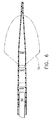
- FIG. 6 shows a cross section of transparent segment 21 and tapered tip 22 of FIG 5 taken at line 6-6 with endoscope 50 positioned inside.
- a field of view 52 is depicted to indicate the area in view by the physician. Because endoscope 50 is movable with respect to dilator 18, a change in the position of endoscope 50 allows the physician to see a different area of body lumen 60 within field of view 52.
- FIGs 7A-7D show four possible steps a physician may use to dilate stricture 61 with dilator 18 and endoscope 50.
- FIG. 7A shows the relative positions of endoscope 50 and dilator 18 upon insertion into body lumen 60 to a location of stricture 61. In this position, field of view 52 is used to view body lumen 60 during insertion, and to view the proximal location of stricture 61.
- FIG 7B shows endoscope 50 at a first viewpoint 53 so field of view 52 includes first outer diameter D1. While viewing plurality of markings 43 for reference, dilator 18 is advanced into stricture 61 causing dilation to first outer diameter D1. Plurality of markings 43 may delineate the boundaries of diameter D1 and may also indicate its numerical value. In this manner, the physician has a visual indication through endoscope 50 of where to position dilator 18 with respect to stricture 61 for precise dilation to a desired diameter.
- FIG. 7C shows a next potential step to further dilate stricture 61 if desired by the physician.
- Endoscope 50 is placed at a second viewpoint 54 relative to dilator 18 so that field of view 52 includes second outer diameter D2.
- the medical device is further advanced into stricture 61 to further dilate to second outer diameter D2 while viewing another portion of plurality of markings 43 for reference.
- FIG. 7D shows endoscope 50 at a third viewpoint 55 so that field of view 52 includes third outer diameter D3.
- the medical device may be further advanced to dilate stricture 61 to third outer diameter D3 while again viewing yet another portion of plurality of markings 43 as a reference. In this manner, the physician can visually examine the entire length of a stricture with endoscope 50 as the dilation occurs.
- An alternative method of use is to first place a guidewire in body lumen 60 of the patient, then thread dilator 18 over that guidewire using second channel 27, conical inner contour 32, and first channel 23. Dilator 18 may then slide into the guidewire, after which endoscope 50 may be placed into first channel 23.
- the guidewire does not need to be threaded through the working channel of endoscope 50, but a physician may do so if desired.
- the combination of endoscope 50, dilator 18, and guidewire could then be used according to the steps illustrated in FIGs. 7A-7D.
- a physician advancing a dilator through a stricture 61 will normally feel resistance.
- perforation or other damage to the body lumen may occur. Further, if such damage occurs, the physician may not immediately recognize that damage has occurred.
- the present invention can permit the physician to visualize a medical procedure (e.g. dilation of a stricture) as the procedure is performed, thereby providing the physician with immediate feedback on the state of the tissue being treated. Such visualization can help in avoiding unintended damage of tissue which might otherwise occur if the physician is not able to directly visualize the procedure. In the unlikely even that damage does occur, the physician can immediately notice it and can choose to cease treatment and begin a new course of action to repair the damage. Direct visualization provided by endoscope 50 inside dilator 18 allows the physician to know that he/she has not perforated, bruised, or otherwise damaged body lumen 60.
- Another useful feature of the dilator 18 is that it provides one with the ability to dilate to more than one diameter with a single introduction of the device, and with precision. This is made possible by the ability to see plurality of markings 43 from inside transparent segment 21 to identify a particular dilating diameter.
- Previously disclosed devices with multiple diameters rely on tactile feedback, remote markings, or costly pressure meters ( e.g. in the case of balloons) to control the diameter.
- the intuitive nature of plurality of markings 43 allows the physician to easily select the desired diameter by looking clearly through the device, along the whole length of stricture 61, adding precision to the device when compared to current methods, which may involve elaborate measuring schemes.
- Dilator 18 can also be less costly to manufacture than some balloon style dilators. Accordingly, devices of the present invention may be cost effectively packaged and sold as a single-use, disposable product which does not require cleaning or re-sterilization. Dilator 18 can be pre-sterilized and packaged in a sterile pouch or other suitable package.
- Dilator 18 can also provide reliability in terms of dilating diameter compared to certain balloon type dilators. Some balloons may not hold a constant diameter when inflated, so the dilation is not as reproducible as a tube of known size being passed through a constricted area. Dilator 18 provides two-vector shearing of stricture 61. This results from sliding a tapered-tip device through a narrowed area, thereby applying forces in both the axial and radial directions. Balloons typically only apply a generally radial directed force to a stricture.
- Dilator 18 can also provide affordable and convenient dilation with the ability to directly visualize the treatment along the entire length (not just a proximal or distal portion) of a stricture 61 without the use of expensive or potentially harmful radiographic equipment to confirm placement.
- a dilation procedure is typically performed in a radiographic suite, which often requires additional logistics of scheduling an additional appointment and different staffing needs, which in turn can require additional time and cost.
- Dilator 18 can provide complete direct visualization with endoscope 50 without the additional costs or time associated with radiographic equipment.
- the present invention has been illustrated as having a transparent segment having generally circular cross-sections, but non-circular cross-sections (e.g. oval, elliptical, polygonal) can also be used, in which case the term “diameter” will be understood to refer to the maximum dimension of the non-circular cross-section used for providing dilation.
- the present invention may be provided in kit form with other medical devices, and the kit elements can be pre-sterlized and packaged in a sealed container or envelope to prevent contamination.
- the present invention may be provided as single use disposable device or alternatively, may be constructed for multiple uses.
Abstract
Description
- The present invention relates to a transparent dilator device for use in a lumen of a patient's body.
- Constriction of natural body lumens, such as those of the human gastrointestinal tract, can occur in numerous ways. Some strictures are caused by muscular spasm, others by disease, and others by injury. Regardless of the cause, the typical method of treatment is to physically dilate the region using a medical device designed for that purpose.
- Several types of devices are used for dilation. One generally established type is a bougie. Bougie tubes may be in the form of a mercury- or tungsten-filled tube with a tapered end that gradually opens the strictured esophagus as it is pushed past the treatment site. These devices come in a series of increasing sizes, each tube having a single effective dilating diameter, generally between 10 and 60 French. (French is a measure of circumference based on the diameter in millimeters, mm.) The bougie is typically introduced blindly after the physician has judged the proper beginning size with an endoscope. Some physicians follow a rule of thumb not to dilate a stricture more than three successive French sizes (3 mm) in a single session. If the lumen has not satisfactorily been opened after three sizes, the patient returns at a later time for another treatment session.
- Another type of device is a wire-guided dilator. These devices are passed into the patient over a guidewire that has been pre-fed along a lumen of the gastrointestinal tract. The guidewire keeps the tip of the device in the lumen while it is being passed, to avoid perforating through the wall of the lumen. These devices have a single outer dilating diameter and typically have a radiopaque component so that they are visible under fluoroscopy. The following patent documents disclose various devices in the art: US 5,366,471; US 6,334,863; US 5,766,202; and GB 2023009A.
- A third type of dilating device is a balloon. Balloon dilators may be comprised of polyethylene, and may be introduced through the working channel of an endoscope. The physician views the proximal end of a stricture site with an endoscope and introduces the deflated balloon into the narrowed area. The balloon is then inflated with saline or other fluid to effectively open the stricture site pneumatically. Balloons provide the advantages of multiple dilator diameters with a single intubation, passage through the working channel of an endoscope, and visualization of a stricture site from the proximal end.
- Other devices such as double tapered bougies, pneumatic bougies, illuminating bougies, solid dilator devices attached to the distal end of an endoscope, and variable stiffness dilators have been previously described in the art. The following patent documents disclose various types of devices in the art: US 6,010,520; US 4,832,691; US 5,624,432; US 5,718,666; WO 98/47422.
- Applicants have recognized the need for a relatively low cost dilator (disposable or non-disposable) which is relatively easy and convenient to use, and which allows the physician to directly visualize the stricture being dilated. In one embodiment, the present invention provides a medical device for use in dilating a body lumen. The medical device comprises at least one generally transparent segment, and a channel associated with the transparent segment for receiving a visualization device. The transparent segment includes at least one outer surface having a diameter sized for providing dilation. In one embodiment, the device can comprise a plurality of transparent sections, each section having an outer surface portion with a different diameter sized for sequential dilation of a stricture. The medical device can include at least one marking associated with the transparent segment for indicating the position and/or value of a dilation diameter.
- The present invention also provides a method for dilating a portion of a body lumen. In one embodiment, the method can comprise the steps of: providing a medical device having at least one outer surface portion sized for providing dilation of a body lumen; inserting said outer surface portion into said lumen; advancing said outer surface portion in said lumen to dilate said lumen; and viewing dilation of said lumen through said outer surface portion of said medical device, such as by viewing the body lumen with a visualization device positioned within a channel in the medical device. The step of viewing dilation can comprise viewing the lumen through a transparent segment of device, wherein the transparent segment includes multiple outer diameters sized and arranged for sequential dilation.
- While the novel features of the invention are set forth with particularity in the appended claims, the invention in all its embodiments may be more fully understood with reference to the following description and accompanying drawings.
- FIG. 1 is a side view of wire-guided
dilator 10, described in prior art, including aguidewire channel 13, afirst radiopaque marker 14, and asecond radiopaque marker 15. - FIG. 2 is a side view of a first embodiment of the present invention, a
dilator 18 which includes ahandle 19, atube 20, atransparent segment 21, and atapered tip 22. - FIG. 3 is a sectional view of
dilator 18 from FIG. 2 with anendoscope 50 inside abody lumen 60, proximal to astricture 61. - FIG. 4 is a detailed view of
transparent segment 21 andtapered tip 22 shown in FIG. 2, including a first outer diameter D1, a conicalinner contour 32 insidetapered tip 22, an exterior taper angle theta1, and a narrow leadingedge 34. - FIG. 5 shows a detail view of a preferred embodiment of
transparent segment 21, including a second outer diameter D2, a third outer diameter D3, a plurality ofmarkings 43, and at least onetransition 44. - FIG 6 shows
endoscope 50 inside a cross section view ofdilator 18 shown in FIG 5, taken at line 6-6, including a field ofview 52. - FIGs. 7A-7D illustrate steps which can be performed in using
dilator 18 with anendoscope 50. FIG. 7A) is a sectional view ofdilator 18 from FIG. 5 and field ofview 52 ofendoscope 50 positioned for advancement intobody lumen 60 to astricture 61. FIG. 7 B) is a sectional view ofdilator 18 from FIG. 5 and field ofview 52 ofendoscope 50 positioned atfirst viewpoint 53 dilating to first outer diameter D1. FIG. 7 C) is a sectional view ofdilator 18 from FIG. 5 and field ofview 52 ofendoscope 50 positioned atsecond viewpoint 54 dilating to second outer diameter D2. FIG. 7 D) is a sectional view ofdilator 18 from FIG. 5 and field ofview 52 ofendoscope 50 positioned atthird viewpoint 55 dilating to third outer diameter D3. -
- The present invention relates to the field of medicine, specifically to surgery, urology, or gastroenterology, in which a physician intends to alter the size of a constricted body lumen in a patient, or otherwise temporarily or permanently enlarge a portion of a body lumen. By way of example, the present invention is illustrated and described for application to an esophageal stricture of a human patient. However, the present invention is applicable for use in other natural lumens of human patients, including the urinary tract, biliary tract, lower gastrointestinal tract, or bronchus; and the present invention may also be used in other animals (e.g. for veterinary medicine), including mammals other than humans.
- FIG. 1 shows a wire-guided
dilator 10 described in prior art, including aguidewire channel 13, afirst radiopaque marker 14, and asecond radiopaque marker 15. Guidewirechannel 13 allows wire-guideddilator 10 to be passed over a previously placed guidewire along the lumen of a patient.First radiopaque marker 14 andsecond radiopaque marker 15 are detectable under fluoroscopy to determine the position of wire-guideddilator 10 relative to a strictured area. This provides confirmation to the physician of dilation to the full diameter of the device. The fluoroscopy procedure can be costly and can expose the physician and patient to radiation. - FIG. 2 shows a
dilator 18 of the present invention, including ahandle 19 at the device's proximal end, atube 20, atransparent segment 21, and atapered tip 22 at its distal end.Handle 19 of FIG. 2 includes a longitudinal channel for receiving an endoscope 50 (see FIG 3).Handle 19 provides the physician a location togrip dilator 18 and may be made from an elastic material, such as silicone. In one embodiment, the proximal portion ofhandle 19 can have an opening (such as an opening in a flexible, elastic seal or boot made of silicone or a suitable flexible elastic polymeric material), the hole being slightly smaller than the diameter of the endoscope. Such an arrangement can provide frictional engagement of thehandle 19 with theendoscope 50 due to the drag force encountered in passing the endoscope through the opening. This feature allows the physician to hold eitherendoscope 50 ortube 20 in a one-handed fashion to position both the endoscope and thedilator 18 with direct visualization of a body lumen 60 (FIG. 3) during introduction or advancement of the device. -
Tube 20 shown in FIG. 2 may be made of a flexible polymer, examples of which include polyvinyl chloride (PVC), thermoplastic elastomer (TPE), polyurethane, or silicone. In one embodiment,tube 20 is made of a transparent flexible polymer, but it may also be made from an opaque material. A suitable transparent material from whichtube 20 can be manufactured is available as 2222RX-70 Clear 000X from Alpha-Gary Corporation (Leominster, MA). Commercially available clear flexible PVC tubing such as Kuri Tec K050 0810 from Kuriyama of America Inc. (Elk Grove Village, IL) may also be used fortube 20. -
First channel 23 of FIG. 2 is appropriately sized to receive endoscope 50 (see FIG. 3). Various endoscopes of varying types and sizes may be used inside the present invention, including, but not limited to, bronchoscopes, colonoscopes, cystoscopes, and gastroscopes.Endoscope 50 may comprise a fiberscope or a videoscope, and may employ a CMOS (Complimentary Metallic Oxide Semiconductor) chip, a miniature camera, or other visualization device. In one embodiment,first channel 23 may be about 2mm greater in diameter than the diameter ofendoscope 50 used in the procedure so that relative motion betweenendoscope 50 anddilator 18 can occur smoothly under physician control. By way of example, a 9.5mm diameter gastroscope could be inserted into an 11.5mm diameterfirst channel 23 ofdilator 18 to dilate an esophageal stricture. However,dilator 18 can be sized and configured to accommodate other endoscopes. In various other embodiments,first channel 23 may have a diameter in the range of, but not limited to, about 3mm to about 15mm. - Fourth outer diameter D4 of FIG 2 can be made as small as feasible for reason of patient tolerance during the procedure. Fourth outer diameter D4 may be the same as the largest diameter of
transparent segment 21, or alternatively, D4 may be less than the largest diameter intransparent segment 21. The dimensions offirst channel 23 and fourth outer diameter D4 determine the wall thickness oftube 20. This wall thickness should provide adequate axial stiffness to advancetransparent segment 21 ofdilator 18past stricture 61 without kinking, when used in conjunction withendoscope 50. The presence ofendoscope 50 insidetube 20 during advancement adds to the stiffness ofdilator 18, and greatly reduces the likelihood of kinking orfolding tube 20 during use. Whentube 20 is made from a flexible polymer such as a flexible PVC material, wall thickness including a range from about 1mm to about 4mm may be used. If a portion oftransparent segment 21 is made from a relatively more rigid material, a wall thickness of 1mm or less may be used. - The length of
tube 20 in FIG. 2 should be appropriately sized to comfortably reach the targeted area within the body while handle 19 remains outside the body for physician control. A low coefficient of friction ontube 20 allows easy sliding along the surface ofbody lumen 60. And, because the physician can repositionendoscope 50 withintube 20 to get a different view, easy sliding ofendoscope 50 withintube 20 may also be desired. A suitable lubricant or low friction material (wet or dry) can be employed. For instance, a lubricating gel may be used to lower the coefficient of friction betweentube 20 andbody lumen 60, and betweenendoscope 50 andtube 20. Likewise, a suitable lubricant or other low friction material (such as acoating 31 shown in Figure 4) could be applied to the inner or outer surfaces (or both) oftube 20 or transparent segment 21 (or both) to facilitate sliding ofendoscope 50 withintube 20 and also sliding oftube 20 withinbody lumen 60. - FIG.3 shows the
dilator 18 being used inbody lumen 60 to dilate astricture 61.Dilator 18 dilatesstricture 61 inbody lumen 60 under direct visualization byendoscope 50 positioned inside the device, allowing the physician to see along the entire length ofstricture 61 from the inside out. The invention replaces the current methods ofdilating body lumen 60 without direct visualization and improves on current methods of dilating with balloons and other devices that allow visualization from only the proximal side ofstricture 61 during the procedure. By way of example, this illustration shows the invention used to dilate an esophageal stricture, but it could be used to dilate constrictions in other body lumens. -
Transparent segment 21 shown in FIG. 4 and in FIG. 5 is a transparent portion of the device through which a physician views thestricture 61 during dilation ofstricture 61.Transparent segment 21 extends from the distal portion oftube 20 and may be made of a transparent material, including clear PVC, TPE, polyurethane, glass, or polycarbonate. Attachment means for attachingtransparent segment 21 totube 20 may include a flange with adhesive, a plurality of mechanical ribs, a plurality of screw-type threads, or other combinations of geometric projections and adhesives.Tube 20 andtransparent segment 21 may also be formed as a single, unitary piece, such as by formingtube 20 andtransparent segment 21 together by molding or casting. Rigid segments may also be incorporated intotransparent segment 21, especially in instances where wall thickness is about 1mm or less. Such rigid segments could be over-molded in place or fixed by adhesive in a desired location. In one embodiment, first channel 23 (FIG. 2) extends intotransparent segment 21 so thatendoscope 50 may be advanced withintransparent segment 21. - The transparency of
transparent segment 21 allows direct visualization of tissue outside the device fromendoscope 50 located within the device. Therefore, it can be desirable to minimize distortion or obstruction of view throughtransparent segment 21. Suitable transparency oftransparent segment 21 can be accomplished by controlling material selection and molding finish. The material from whichtransparent segment 21 is constructed should be clear, and the mold used should be polished so that the molded part has a smooth outer surface.Transparent segment 21 may include markings 43 (Figure 5) such as one ormore markings 43 indicating the outside diameter oftransparent segment 21 at the longitudinal position of the particular marking. Anatomical landmarks, color variations, tissue differences, foreign bodies, and any markings 43 (FIG. 5), and other items of interest should be recognizable when viewed withendoscope 50 disposed withintransparent segment 21. An appropriate material fortransparent segment 21 can have a haze value of about 5% or less, and have a light transmission property of about 80% or greater. Haze value is a material property, expressed in percent, describing the amount of "cloudiness" in a material caused by particulate impurities, molecular structure, or degree of crystallinity, resulting in scattering of light and apparent cloudiness. Light transmission is a material property indicating the percentage of incident light that passes through an object. In addition to using transparent material to formsegment 21, a mold used to createsegment 21 can be highly polished to create a smooth surface that does not distort the view seen throughendoscope 50 when the viewing device of endoscope is disposed insidesegment 21 to view lumen tissue outside ofsegment 21. - Having a low coefficient of friction of
transparent segment 21 allows the device to slide freely insidebody lumen 60, especially during dilation ofstricture 61. Lubricating gel, such as K-Y brand lubricating jelly available from Johnson and Johnson can be used to lower the coefficient of friction during use. In one embodiment, a coating 31 (FIG. 2) can be disposed on one or both of the inner and outer surfaces of thetransparent segment 21, in whichcoating 31 is transparent and has a lower coefficient of friction when hydrated than when dry. One example ofcoating 31 is a hydrogel material made by the interaction of polyvinylpyrrolidone with one or more isocyanate prepolymers. A coating such as Hydromer® Lubricious Medical Coatings by Hydromer Inc. (Somerville, NJ) can be used forcoating 31. Such a coating can reduce the drag force along the axis of a lumen during dilation, creating a more efficient device when compared to existing dilators. - FIG. 4 shows a section view of
dilator 18 including a first outer diameter D1 and a taperedtip 22.Tapered tip 22 may be made of a flexible polymer that is pliable compared to body tissue and may be attached to the distal end oftransparent segment 21. In one embodiment, taperedtip 22 can be made with the same material astransparent segment 21, iftransparent segment 21 is made of a flexible polymer. In one embodiment, a biomedical grade of clear flexible PVC having a hardness value of about 60 to 80 on the Shore A scale can be used to form taperedtip 22 andtransparent segment 21. For example, a clear flexible PVC material such as XV-3450 from PolyOne Corp. (Avon Lake, OH) could be used to mold bothtransparent segment 21 and taperedtip 22 as a single part. Another material from whichtip 22 andsegment 21 may be formed is material designated 2222RX-70 Clear 000X from Alpha-Gary Corp (Leominster, MA), which material can be gamma stable to allow gamma radiation to be used for sterilization. Other suitable materials such as TPE or polyurethane can also be used. -
Tapered tip 22 facilitates intubation intobody lumen 60 by gradually tapering from a first outer diameter D1 to a narrow leadingsegment 34 with an exterior taper angle theta1, as shown in FIG. 4. In one embodiment, taperedtip 22 includes asecond channel 27 in communication with a conicalinner contour 32 andfirst channel 23 so that the device can be threaded over a guidewire.Second channel 27 can be sized appropriately for a guidewire, including diameters in the range from about 0.5mm to about 1.5mm. Exterior taper angle thetal can be selected to provide a desired amount of radial force transmitted againststricture 61 for a given level of axial force (force parallel to length of the dilator 18) applied by the physician. Generally, a low value of exterior taper angle provides an efficient, comfortable transmission of radial force against the stricture, with the trade-off that low values of exterior taper angle generally increase the length of thedilator 18 that must be inserted past the stricture. For instance and without limitation, the dilator can have an exterior taper angle theta in a range including about 3 degrees to about 15 degrees. In one embodiment, the taper angle can be between about 6.5 and about 7.5 degrees. - FIG. 4 shows conical
inner contour 32 connectingfirst channel 23 tosecond channel 27 with an interior taper angle theta2. The connection has a conical shape to reduce the glare fromendoscope 50 during use. Conicalinner contour 32 also facilitates molding by allowing a central core pin to be tapered for ease of removal. In one embodiment, the value of interior taper angle theta2 is different from value of exterior taper angle theta1 to provide a varying wall thickness along the length of the device, so that radial strength can be tailored as needed along the length of the device. By way of example, the exterior taper angle theta1 can be about 7 degrees, and the interior taper angle theta2 can be about 6 degrees. - In FIG. 4, conical inner contour is shown initiating at the distal end of a segment with first outer diameter D1, but other initiation locations are possible. For example, if conical
inner contour 32 initiates at a more proximal location (e.g. forward of the "14 mm" marking in Figure 4), a thicker wall is created at the distal portion of a segment with first outer diameter D1, providing radial stiffness to that area while still allowingendoscope 50 to slide far enough to view out taperedtip 22 during insertion. Such an arrangement can help ensure adequate radial strength of in the portion of the device having inner diameter D1. - FIG. 5 depicts a preferred embodiment of
transparent segment 21 comprised of a firsttransparent section 21A having a first outer diameter D1; a secondtransparent section 21B having a second outer diameter D2, and a thirdtransparent section 21C having a third outer diameter D3, each pair of adjacent sections separated by atransition 44. The first, second and third sections can each be generally cylindrical.Transitions 44 provide a tapered (linear or curvilinear ) transition in diameter from the outer diameter of one section to the outer diameter of the adjacent section. The transitions can have can have a hollow conical configuration, such as a conical shape generally the same as that of a truncated cone having a centrally located passageway. Alternatively, thedilator 18 can have diameters D1, D2, D3, and D4 on a single continuous outer surface portion which is tapered linearly or curvilinearly from D1 to D4. - Figure 5 also shows plurality of
markings 43 for the physician to select and position the desired dilating diameter in the area ofstricture 61 during the procedure.Markings 43 provided to be visible through the optical device (e.g. camera, fiber optic cable, etc.) associated with theendoscope 50 and may have several uses, including delineating the boundaries of a single dilating diameter, or indicating the numeric value of a dilating diameter.Markings 43 may be molded into the part, applied with ink, etched on the device, or applied by any other suitable method. In one embodiment, numerical indications may be applied to the outer surface oftransparent segment 21 in multiple locations, some of which are readable byendoscope 50 from inside the device (necessitating them to appear backwards from the exterior of the device, but appearing forward from inside the device), and some of which are readable from the exterior of the device (appear backward fromendoscope 50 inside the device). In addition to markings comprising numerals or letters, other embodiments of plurality ofmarkings 43 may include use of various other indicia, including without limitation one or more different colors, and/or use of different geometric shapes, such as to designate different sections or segments, or attributes of different portions of the device. For instance, a row or column of circles could be used to designate a first section, a pattern of circles and dashes could designate a second section, and a pattern of circles, dashes, and squares could designate a third section.Markings 43 can also be coated or otherwise treated with a substance to make them luminous or glow in reduced lighting. - FIG. 6 shows a cross section of
transparent segment 21 and taperedtip 22 of FIG 5 taken at line 6-6 withendoscope 50 positioned inside. A field ofview 52 is depicted to indicate the area in view by the physician. Becauseendoscope 50 is movable with respect todilator 18, a change in the position ofendoscope 50 allows the physician to see a different area ofbody lumen 60 within field ofview 52. - FIGs 7A-7D show four possible steps a physician may use to dilate
stricture 61 withdilator 18 andendoscope 50. FIG. 7A shows the relative positions ofendoscope 50 anddilator 18 upon insertion intobody lumen 60 to a location ofstricture 61. In this position, field ofview 52 is used to viewbody lumen 60 during insertion, and to view the proximal location ofstricture 61. - FIG 7B shows
endoscope 50 at afirst viewpoint 53 so field ofview 52 includes first outer diameter D1. While viewing plurality ofmarkings 43 for reference,dilator 18 is advanced intostricture 61 causing dilation to first outer diameter D1. Plurality ofmarkings 43 may delineate the boundaries of diameter D1 and may also indicate its numerical value. In this manner, the physician has a visual indication throughendoscope 50 of where to positiondilator 18 with respect tostricture 61 for precise dilation to a desired diameter. - FIG. 7C shows a next potential step to further dilate
stricture 61 if desired by the physician.Endoscope 50 is placed at asecond viewpoint 54 relative todilator 18 so that field ofview 52 includes second outer diameter D2. The medical device is further advanced intostricture 61 to further dilate to second outer diameter D2 while viewing another portion of plurality ofmarkings 43 for reference. - FIG. 7D shows
endoscope 50 at athird viewpoint 55 so that field ofview 52 includes third outer diameter D3. Again, the medical device may be further advanced to dilatestricture 61 to third outer diameter D3 while again viewing yet another portion of plurality ofmarkings 43 as a reference. In this manner, the physician can visually examine the entire length of a stricture withendoscope 50 as the dilation occurs. - An alternative method of use is to first place a guidewire in
body lumen 60 of the patient, thenthread dilator 18 over that guidewire usingsecond channel 27, conicalinner contour 32, andfirst channel 23.Dilator 18 may then slide into the guidewire, after which endoscope 50 may be placed intofirst channel 23. The guidewire does not need to be threaded through the working channel ofendoscope 50, but a physician may do so if desired. The combination ofendoscope 50,dilator 18, and guidewire could then be used according to the steps illustrated in FIGs. 7A-7D. - A physician advancing a dilator through a
stricture 61 will normally feel resistance. In prior art devices where the physician attempts to "blindly" introduce a dilator, perforation or other damage to the body lumen may occur. Further, if such damage occurs, the physician may not immediately recognize that damage has occurred. The present invention can permit the physician to visualize a medical procedure (e.g. dilation of a stricture) as the procedure is performed, thereby providing the physician with immediate feedback on the state of the tissue being treated. Such visualization can help in avoiding unintended damage of tissue which might otherwise occur if the physician is not able to directly visualize the procedure. In the unlikely even that damage does occur, the physician can immediately notice it and can choose to cease treatment and begin a new course of action to repair the damage. Direct visualization provided byendoscope 50 insidedilator 18 allows the physician to know that he/she has not perforated, bruised, or otherwise damagedbody lumen 60. - Another useful feature of the
dilator 18 is that it provides one with the ability to dilate to more than one diameter with a single introduction of the device, and with precision. This is made possible by the ability to see plurality ofmarkings 43 from insidetransparent segment 21 to identify a particular dilating diameter. Previously disclosed devices with multiple diameters rely on tactile feedback, remote markings, or costly pressure meters ( e.g. in the case of balloons) to control the diameter. The intuitive nature of plurality ofmarkings 43 allows the physician to easily select the desired diameter by looking clearly through the device, along the whole length ofstricture 61, adding precision to the device when compared to current methods, which may involve elaborate measuring schemes. -
Dilator 18 can also be less costly to manufacture than some balloon style dilators. Accordingly, devices of the present invention may be cost effectively packaged and sold as a single-use, disposable product which does not require cleaning or re-sterilization.Dilator 18 can be pre-sterilized and packaged in a sterile pouch or other suitable package. -
Dilator 18 can also provide reliability in terms of dilating diameter compared to certain balloon type dilators. Some balloons may not hold a constant diameter when inflated, so the dilation is not as reproducible as a tube of known size being passed through a constricted area.Dilator 18 provides two-vector shearing ofstricture 61. This results from sliding a tapered-tip device through a narrowed area, thereby applying forces in both the axial and radial directions. Balloons typically only apply a generally radial directed force to a stricture. -
Dilator 18 can also provide affordable and convenient dilation with the ability to directly visualize the treatment along the entire length (not just a proximal or distal portion) of astricture 61 without the use of expensive or potentially harmful radiographic equipment to confirm placement. When using radiographic equipment, a dilation procedure is typically performed in a radiographic suite, which often requires additional logistics of scheduling an additional appointment and different staffing needs, which in turn can require additional time and cost.Dilator 18 can provide complete direct visualization withendoscope 50 without the additional costs or time associated with radiographic equipment. - The present invention has been illustrated as having a transparent segment having generally circular cross-sections, but non-circular cross-sections (e.g. oval, elliptical, polygonal) can also be used, in which case the term "diameter" will be understood to refer to the maximum dimension of the non-circular cross-section used for providing dilation. The present invention may be provided in kit form with other medical devices, and the kit elements can be pre-sterlized and packaged in a sealed container or envelope to prevent contamination. The present invention may be provided as single use disposable device or alternatively, may be constructed for multiple uses.
- While various embodiments of the present invention have been disclosed, it will be obvious to those skilled in the art that such embodiments are provided by way of example only. Further, each element or component of the present invention may be alternatively described as a means for performing the function or functions performed by the element or component. Numerous variations, changes, and substitutions will now occur to those skilled in the art without departing from the invention. Accordingly, it is intended that the invention be limited only by the spirit and scope of the appended claims.
Claims (17)
- A medical device for use in dilating a body lumen, the medical device comprising at least one generally transparent segment, and wherein said transparent segment includes at least one outer surface having a diameter sized for providing dilation.
- The medical device of Claim 1 wherein said transparent segment comprises a plurality of outer surface portions, each outer surface portion having a different diameter, and said diameters sized for providing sequential dilation of a stricture.
- The medical device of Claim 2 wherein said transparent segment comprises at least three outer surface portions, each outer surface portion having a different diameter.
- The medical device of Claim 1 wherein said transparent segment comprises at least one marking for indicating the position of a diameter sized for providing dilation.
- The medical device of Claim 1 wherein said transparent segment comprises at least one marking for indicating the size of a diameter for providing dilation.
- The medical device Claim 1 further comprising a channel associated with said transparent segment, said channel sized for receiving an endoscope.
- A medical device for use with an endoscope in dilating a body lumen, the medical device comprising a generally transparent segment comprising at least one outer surface portion having a first outer diameter sized for providing dilation of a body lumen, and a first channel extending at least partially into said transparent segment, wherein the channel is sized for receiving an endoscope.
- The medical device of claim 7 further comprising a plurality of markings on said transparent segment, wherein said plurality of markings are viewable with an endoscope positioned in said channel.
- The medical device of claim 8 wherein said plurality of markings delineates the portion of said transparent segment having said first outer diameter.
- The medical device of claim 8 wherein said plurality of markings indicates the numeric value of said first outer diameter.
- The medical device of claim 7 further comprising a tapered tip and a second channel in said tapered tip in communication with said first channel, said second channel for receiving a guidewire.
- The medical device of claim 7 further comprising a coating for reducing friction, wherein said coating is generally transparent.
- The medical device of claim 12 wherein said coating is located on the inner surface of said transparent segment.
- The medical device of claim 12 wherein said coating is located on the outer surface of said transparent segment.
- The medical device of claim 7 further comprising a handle positioned proximally of said transparent segment, wherein said handle includes a longitudinal channel in communication with said first channel for receiving the endoscope.
- The medical device of claim 7, wherein said transparent segment further comprises:a second outer diameter proximal to said first outer diameter, wherein said second outer diameter is larger than said first outer diameter; anda third outer diameter proximal to said second outer diameter, wherein said third outer diameter is larger than said second outer diameter.
- A medical device for use with an endoscope, comprising:a tube comprising a first channel for receiving the endoscope;a transparent segment extending distally of said tube, said transparent segment for dilating a body lumen, said transparent segment having a first outer diameter, a second outer diameter, and a third outer diameter, said diameters arranged to provide sequential dilation;a plurality of markings visable with an endoscope disposed in said first channel, wherein said plurality of markings delineate a portion of said transparent segment having said first outer diameter, said second outer diameter, and said third outer diameter; anda tapered tip extending distally of said transparent segment.
Applications Claiming Priority (2)
| Application Number | Priority Date | Filing Date | Title |
|---|---|---|---|
| US324597 | 2002-12-20 | ||
| US10/324,597 US7309344B2 (en) | 2002-12-20 | 2002-12-20 | Transparent dilator device and method of use |
Publications (3)
| Publication Number | Publication Date |
|---|---|
| EP1430926A2 true EP1430926A2 (en) | 2004-06-23 |
| EP1430926A3 EP1430926A3 (en) | 2004-11-24 |
| EP1430926B1 EP1430926B1 (en) | 2007-01-31 |
Family
ID=32393072
Family Applications (1)
| Application Number | Title | Priority Date | Filing Date |
|---|---|---|---|
| EP03258098A Expired - Lifetime EP1430926B1 (en) | 2002-12-20 | 2003-12-22 | Transparent dilator device |
Country Status (10)
| Country | Link |
|---|---|
| US (2) | US7309344B2 (en) |
| EP (1) | EP1430926B1 (en) |
| JP (1) | JP4601947B2 (en) |
| CN (1) | CN100408124C (en) |
| AT (1) | ATE353023T1 (en) |
| AU (1) | AU2003270939B2 (en) |
| BR (1) | BR0305966B1 (en) |
| CA (1) | CA2453743C (en) |
| DE (1) | DE60311564T2 (en) |
| ES (1) | ES2279934T3 (en) |
Cited By (3)
| Publication number | Priority date | Publication date | Assignee | Title |
|---|---|---|---|---|
| EP1647233A1 (en) * | 2004-10-15 | 2006-04-19 | Ethicon Endo-Surgery, Inc. | Transparent dilator device |
| US7309344B2 (en) | 2002-12-20 | 2007-12-18 | Ethicon Endo-Surgery, Inc. | Transparent dilator device and method of use |
| US11565092B2 (en) | 2018-03-06 | 2023-01-31 | Alpine Medical Devices, Llc | Endoscopic dilator |
Families Citing this family (43)
| Publication number | Priority date | Publication date | Assignee | Title |
|---|---|---|---|---|
| JP4716757B2 (en) * | 2005-03-03 | 2011-07-06 | オリンパスメディカルシステムズ株式会社 | Balloon dilator |
| US8066730B2 (en) * | 2005-11-14 | 2011-11-29 | Scapa Flow, Llc | Medical dilator system or dilator device |
| WO2007098416A2 (en) * | 2006-02-16 | 2007-08-30 | University Of South Florida | Eccentric dilation balloons for use of endoscopes |
| US20070233221A1 (en) * | 2006-03-31 | 2007-10-04 | The Board Of Regents, The University Of Texas System | Esophageal dilation and stent delivery system and method of use |
| US20090306472A1 (en) * | 2007-01-18 | 2009-12-10 | Filipi Charles J | Systems and techniques for endoscopic dilation |
| US8920305B2 (en) | 2007-01-19 | 2014-12-30 | Advanced Bariatric Technology, Llc | Vertically oriented band for stomach |
| US7695469B2 (en) * | 2007-01-25 | 2010-04-13 | Biolase Technology, Inc. | Electromagnetic energy output system |
| US20090024089A1 (en) * | 2007-04-25 | 2009-01-22 | Levine Jonathan A | Long tapered dilator |
| US8211136B2 (en) * | 2007-08-31 | 2012-07-03 | Kimberly-Clark Worldwide, Inc. | Stoma dilator |
| EP2303390A4 (en) * | 2008-06-03 | 2011-11-30 | Svip 8 Llc | Tissue-anchored devices |
| US9050049B2 (en) * | 2008-06-12 | 2015-06-09 | Daniel David Ryan | Urethra gauge and methods of manufacture, and operation thereof |
| JP5709747B2 (en) * | 2008-07-28 | 2015-04-30 | スパイン ビュー, インコーポレイテッド | Penetration member with direct visualization |
| JP2010029491A (en) * | 2008-07-30 | 2010-02-12 | Hiromi Nagano | Endoscope hood and diagnosis-treatment method using endoscope hood |
| JP2010029584A (en) * | 2008-07-31 | 2010-02-12 | Nippon Sherwood Medical Industries Ltd | Nasal cavity expanding device and nasal cavity protection tube insertion set |
| US8083690B2 (en) * | 2008-09-04 | 2011-12-27 | Vascular Solutions, Inc. | Convertible guidewire system and methods |
| ES2671595T3 (en) | 2010-01-29 | 2018-06-07 | Advanced Bariatric Technology, Llc | Surgical clamp |
| US10376331B2 (en) | 2010-02-12 | 2019-08-13 | Intuitive Surgical Operations, Inc. | Sheaths for jointed instruments |
| US9089351B2 (en) | 2010-02-12 | 2015-07-28 | Intuitive Surgical Operations, Inc. | Sheath for surgical instrument |
| EP2590586B1 (en) | 2010-07-09 | 2014-08-06 | Intuitive Surgical Operations, Inc. | Electrosurgical tool cover |
| US10426606B2 (en) * | 2010-08-23 | 2019-10-01 | Edwards Lifesciences Corporation | Color-coded prosthetic valve system and methods for using the same |
| US20120123463A1 (en) * | 2010-11-11 | 2012-05-17 | Moises Jacobs | Mechanically-guided transoral bougie |
| JP5784900B2 (en) * | 2010-12-14 | 2015-09-24 | 学校法人自治医科大学 | Endoscope hood |
| US10485524B2 (en) | 2011-10-25 | 2019-11-26 | Essential Medical, Inc. | Instrument and methods for surgically closing percutaneous punctures |
| CN102772850A (en) * | 2012-07-06 | 2012-11-14 | 马涛 | Medical dilation device |
| RU2742019C2 (en) | 2012-08-09 | 2021-02-01 | ЭДВАНСТ БАРИАТРИК ТЕКНОЛОДЖИ, ЭлЭлСи | Polymer bariatric clamp molded by multilayer casting and method of its installation |
| WO2014150154A1 (en) | 2013-03-15 | 2014-09-25 | Essential Medical, Inc. | Vascular closure devices and methods of use |
| US9919119B2 (en) | 2013-07-31 | 2018-03-20 | Shannon Sovndal | Gum elastic bougie introducer with tactile depth and orientation indicator |
| EP3858254A1 (en) | 2013-12-23 | 2021-08-04 | Arrow International LLC | Vascular closure device |
| AU2015237836B2 (en) * | 2014-03-24 | 2019-09-19 | Boston Scientific Medical Device Limited | Medical apparatus for fluid communication |
| SG11201701503YA (en) | 2014-08-26 | 2017-03-30 | Advanced Bariatric Technology Llc | Bariatric clamp with suture portions, magnetic inserts and curvature |
| US9636144B2 (en) | 2014-10-09 | 2017-05-02 | Coopersurgical, Inc. | Uterine manipulators and related components and methods |
| US20160175516A1 (en) * | 2014-12-22 | 2016-06-23 | Boston Scientific Scimed, Inc. | Apparatus for increased dye flow |
| US9808598B2 (en) | 2015-02-04 | 2017-11-07 | Teleflex Medical Incorporated | Flexible tip dilator |
| US20160331207A1 (en) * | 2015-05-13 | 2016-11-17 | Tamer Ibrahim | Access visualization systems |
| US10555727B2 (en) | 2015-06-26 | 2020-02-11 | Essential Medical, Inc. | Vascular closure device with removable guide member |
| US11337839B2 (en) | 2016-07-07 | 2022-05-24 | Advanced Bariatric Technology, Llc | Inflatable bariatric clamp |
| WO2018048538A1 (en) * | 2016-09-08 | 2018-03-15 | Napolez Adolfo | Gastrostomy tube reinsertion device |
| US20180221052A1 (en) * | 2017-02-02 | 2018-08-09 | Galen Ohnmacht | Anti-fouling cannulas for endoscopic ports |
| US10668253B2 (en) | 2017-07-11 | 2020-06-02 | Teleflex Life Sciences Limited | Methods for exchanging devices |
| US11020224B2 (en) | 2017-07-11 | 2021-06-01 | Teleflex Life Sciences Limited | Methods for exchanging devices |
| WO2019023279A1 (en) | 2017-07-24 | 2019-01-31 | Advanced Bariatric Technology, Llc | Improved clamp installation tool |
| ES2725873B2 (en) * | 2018-03-27 | 2020-07-09 | Gil Jorge Gutierrez | ENDOTRACHAL DILATION AND VENTILATION DEVICE |
| US10932819B2 (en) | 2018-04-18 | 2021-03-02 | Coopersurgical, Inc. | Uterine manipulators and related components and methods |
Citations (5)
| Publication number | Priority date | Publication date | Assignee | Title |
|---|---|---|---|---|
| US5188596A (en) * | 1990-09-27 | 1993-02-23 | Mentor Corporation | Transparent prostate dilation balloon and scope |
| US5603991A (en) * | 1995-09-29 | 1997-02-18 | Target Therapeutics, Inc. | Method for coating catheter lumens |
| US5733241A (en) * | 1996-02-01 | 1998-03-31 | King; George Hwa Kou | Fiberoptic intubation stylet |
| US5968065A (en) * | 1995-07-13 | 1999-10-19 | Origin Medsystems, Inc. | Tissue separation cannula |
| WO2001012255A1 (en) * | 1999-08-12 | 2001-02-22 | Wilson-Cook Medical Inc. | Dilation balloon having multiple diameters |
Family Cites Families (73)
| Publication number | Priority date | Publication date | Assignee | Title |
|---|---|---|---|---|
| US719487A (en) | 1901-09-16 | 1903-02-03 | William E Minor | Dilator. |
| US2067031A (en) * | 1934-03-23 | 1937-01-05 | Wappler Frederick Charles | Instrument for insertion into constricted body cavities |
| US3169527A (en) * | 1963-05-13 | 1965-02-16 | Sheridan Corp | Lubricated catheter |
| US4195624A (en) | 1978-06-09 | 1980-04-01 | Douglas Donald D | Tubular sheath for facilitating the insertion of an endoscope |
| GB2023009B (en) | 1978-06-14 | 1983-01-12 | Celestin L R | Dilarion device |
| US4217045A (en) * | 1978-12-29 | 1980-08-12 | Ziskind Stanley H | Capsule for photographic use in a walled organ of the living body |
| DE3025785C2 (en) * | 1980-07-08 | 1984-08-16 | Storz, Karl, 7200 Tuttlingen | Dilator, method for its use and device for carrying out the method |
| US4571239A (en) | 1982-03-01 | 1986-02-18 | Heyman Arnold M | Catheter-stylet assembly for slipover urethral instruments |
| JPS59143439U (en) * | 1983-03-14 | 1984-09-26 | 日本ゼオン株式会社 | expansion tube |
| CH656312A5 (en) | 1983-05-18 | 1986-06-30 | Wilson Cook Medical Inc | Expansion of instrument. |
| GB2164854A (en) | 1984-09-27 | 1986-04-03 | Keymed | A wire guided dilator device |
| US4646722A (en) * | 1984-12-10 | 1987-03-03 | Opielab, Inc. | Protective endoscope sheath and method of installing same |
| CH661665A5 (en) | 1984-12-27 | 1987-08-14 | Wilson Cook Medical Inc | Device for fitting an oesophageal prosthesis |
| DE8513185U1 (en) | 1985-05-04 | 1985-07-04 | Koss, Walter, 6222 Geisenheim | Endotube |
| EP0206998B1 (en) * | 1985-06-21 | 1993-03-17 | Ciba-Geigy Ag | Lubricant compositions, glucamin derivatives and complex compounds containing them |
| DE3610091A1 (en) | 1986-03-25 | 1987-10-01 | Witzel Lothar | PNEUMATIC BOUGIE, IN PARTICULAR FOR TREATING STENOSES |
| US4718666A (en) * | 1986-04-03 | 1988-01-12 | Donnell Jerry L O | Upper body exercise device |
| JPS6486983A (en) * | 1987-09-30 | 1989-03-31 | Nippon Zeon Co | Bodily organ dilator |
| US4773394A (en) * | 1987-10-14 | 1988-09-27 | Reichstein Irving P | Upper gastrointestinal endoscope intubator |
| US4871358A (en) * | 1987-11-09 | 1989-10-03 | Gold Steven K | Externally-based inversionary tube |
| US4862891A (en) * | 1988-03-14 | 1989-09-05 | Canyon Medical Products | Device for sequential percutaneous dilation |
| GB8817032D0 (en) | 1988-07-18 | 1988-08-24 | Rowland A C | Light delivery system |
| US5217441A (en) * | 1989-08-15 | 1993-06-08 | United States Surgical Corporation | Trocar guide tube positioning device |
| JPH03136630A (en) * | 1989-10-24 | 1991-06-11 | Olympus Optical Co Ltd | Endoscope guide tube |
| US5006106A (en) | 1990-10-09 | 1991-04-09 | Angelchik Jean P | Apparatus and method for laparoscopic implantation of anti-reflux prosthesis |
| US5158543A (en) * | 1990-10-30 | 1992-10-27 | Lazarus Harrison M | Laparoscopic surgical system and method |
| US5624432A (en) | 1991-10-07 | 1997-04-29 | Angelchik; Jean P. | Illuminating bougie and methods for diagnostic, therapeutic and surgical procedures |
| US5366471A (en) | 1993-10-26 | 1994-11-22 | Pilling Co. | Esophageal dilation bougie |
| US5411016A (en) * | 1994-02-22 | 1995-05-02 | Scimed Life Systems, Inc. | Intravascular balloon catheter for use in combination with an angioscope |
| US5681344A (en) * | 1995-02-06 | 1997-10-28 | Wilson-Cook Medical Inc. | Esophageal dilation balloon catheter containing flexible nitinol wire |
| US5980549A (en) * | 1995-07-13 | 1999-11-09 | Origin Medsystems, Inc. | Tissue separation cannula with dissection probe and method |
| US5718666A (en) | 1996-02-29 | 1998-02-17 | Bioenterics Corporation | Transilluminating bougie |
| US5766202A (en) | 1997-01-21 | 1998-06-16 | Pilling Weck Incorporated | Wire-guided esophagael bougie |
| AU8415498A (en) | 1997-04-21 | 1998-11-13 | Barry David Brighton | An endoscopic apparatus |
| US6033361A (en) * | 1997-06-02 | 2000-03-07 | General Surgical Innovations, Inc. | Vascular retractor |
| JP3748994B2 (en) * | 1997-08-22 | 2006-02-22 | オリンパス株式会社 | Endoscope fitting |
| JP3429685B2 (en) * | 1997-10-06 | 2003-07-22 | オリンパス光学工業株式会社 | Endoscope guide tube |
| US5947296A (en) * | 1997-10-30 | 1999-09-07 | Schneider/Namic | Multipack package |
| US6796976B1 (en) * | 1998-03-06 | 2004-09-28 | Scimed Life Systems, Inc. | Establishing access to the body |
| US6010520A (en) * | 1998-05-01 | 2000-01-04 | Pattison; C. Phillip | Double tapered esophageal dilator |
| US5916145A (en) * | 1998-08-07 | 1999-06-29 | Scimed Life Systems, Inc. | Device and method of using a surgical assembly with mesh sheath |
| US7485092B1 (en) * | 1998-08-12 | 2009-02-03 | Maquet Cardiovascular Llc | Vessel harvesting apparatus and method |
| US6743218B2 (en) * | 1999-01-15 | 2004-06-01 | Cathlogic, Inc. | Retractable catheter systems and associated methods |
| US6527704B1 (en) * | 1999-03-10 | 2003-03-04 | Stryker Corporation | Endoscopic camera system integrated with a trocar sleeve |
| WO2000069350A1 (en) * | 1999-05-19 | 2000-11-23 | Innerdyne, Inc. | System and method for establishing vascular access |
| US6238404B1 (en) * | 1999-09-16 | 2001-05-29 | Benito Hidalgo | Multipurpose medical device |
| US6726659B1 (en) * | 1999-12-09 | 2004-04-27 | John E. Stocking | Catheter assembly having a fenestrated dilator |
| US6334863B1 (en) | 2000-03-22 | 2002-01-01 | Rusch, Inc. | Apparatus and method providing an insertion medical device |
| JP4472849B2 (en) * | 2000-10-06 | 2010-06-02 | 株式会社町田製作所 | Endoscopic device for blood vessel inner wall |
| US20020133128A1 (en) * | 2001-03-16 | 2002-09-19 | Heller Andrew S. | Method and apparatus for dilating an orifice in biological tissue |
| US20020177847A1 (en) * | 2001-03-30 | 2002-11-28 | Long Gary L. | Endoscopic ablation system with flexible coupling |
| JP3560931B2 (en) * | 2001-04-26 | 2004-09-02 | オリンパス株式会社 | Endoscope insertion aid |
| US6673058B2 (en) * | 2001-06-20 | 2004-01-06 | Scimed Life Systems, Inc. | Temporary dilating tip for gastro-intestinal tubes |
| US6916330B2 (en) * | 2001-10-30 | 2005-07-12 | Depuy Spine, Inc. | Non cannulated dilators |
| CA2363473C (en) * | 2001-11-20 | 2010-10-19 | Marc G. Morin | Anoscope |
| JP4430939B2 (en) * | 2001-12-26 | 2010-03-10 | イエール ユニバーシティ | Blood vessel |
| US6953431B2 (en) * | 2002-04-11 | 2005-10-11 | University Of South Florida | Eccentric dilation balloons for use with endoscopes |
| US6652442B2 (en) * | 2002-04-23 | 2003-11-25 | Acueity, Inc. | Micro-endoscope assembly for intraductal brachytherapy of a mammary duct and method of using same |
| US20040068235A1 (en) * | 2002-10-07 | 2004-04-08 | Hallam Clive T. | Packaging system for a medical device and particularly a punctum plug insertion device |
| US6958035B2 (en) * | 2002-10-15 | 2005-10-25 | Dusa Pharmaceuticals, Inc | Medical device sheath apparatus and method of making and using same |
| ES2570595T3 (en) * | 2002-10-31 | 2016-05-19 | Smiths Group Plc | Dilator |
| US20050070949A1 (en) * | 2002-12-20 | 2005-03-31 | Bakos Gregory J. | Transparent dilator device and method of use |
| US7309344B2 (en) | 2002-12-20 | 2007-12-18 | Ethicon Endo-Surgery, Inc. | Transparent dilator device and method of use |
| US20070185522A1 (en) * | 2003-01-21 | 2007-08-09 | Gareth Davies | Dilator |
| DK1466563T3 (en) * | 2003-03-28 | 2006-03-13 | Wolf Gmbh Richard | Dilation system |
| US20060004398A1 (en) * | 2004-07-02 | 2006-01-05 | Binder Lawrence J Jr | Sequential dilator system |
| US9387313B2 (en) * | 2004-08-03 | 2016-07-12 | Interventional Spine, Inc. | Telescopic percutaneous tissue dilation systems and related methods |
| US8066730B2 (en) * | 2005-11-14 | 2011-11-29 | Scapa Flow, Llc | Medical dilator system or dilator device |
| US8845726B2 (en) * | 2006-10-18 | 2014-09-30 | Vertiflex, Inc. | Dilator |
| US20080234719A1 (en) * | 2007-03-22 | 2008-09-25 | Justin Bruce Adams | Vaginal dilator for use in vaginal rehabilitation and methods therefor |
| US20090024089A1 (en) * | 2007-04-25 | 2009-01-22 | Levine Jonathan A | Long tapered dilator |
| US8211136B2 (en) * | 2007-08-31 | 2012-07-03 | Kimberly-Clark Worldwide, Inc. | Stoma dilator |
| JP5301820B2 (en) * | 2007-11-28 | 2013-09-25 | オリンパスメディカルシステムズ株式会社 | Endoscopic incision system |
-
2002
- 2002-12-20 US US10/324,597 patent/US7309344B2/en not_active Expired - Lifetime
-
2003
- 2003-12-16 AU AU2003270939A patent/AU2003270939B2/en not_active Ceased
- 2003-12-19 CA CA2453743A patent/CA2453743C/en not_active Expired - Fee Related
- 2003-12-19 JP JP2003422908A patent/JP4601947B2/en not_active Expired - Lifetime
- 2003-12-20 CN CNB2003101097928A patent/CN100408124C/en not_active Expired - Lifetime
- 2003-12-22 BR BRPI0305966-9A patent/BR0305966B1/en active IP Right Grant
- 2003-12-22 AT AT03258098T patent/ATE353023T1/en not_active IP Right Cessation
- 2003-12-22 ES ES03258098T patent/ES2279934T3/en not_active Expired - Lifetime
- 2003-12-22 EP EP03258098A patent/EP1430926B1/en not_active Expired - Lifetime
- 2003-12-22 DE DE60311564T patent/DE60311564T2/en not_active Expired - Lifetime
-
2007
- 2007-10-11 US US11/870,594 patent/US20090137870A1/en not_active Abandoned
Patent Citations (5)
| Publication number | Priority date | Publication date | Assignee | Title |
|---|---|---|---|---|
| US5188596A (en) * | 1990-09-27 | 1993-02-23 | Mentor Corporation | Transparent prostate dilation balloon and scope |
| US5968065A (en) * | 1995-07-13 | 1999-10-19 | Origin Medsystems, Inc. | Tissue separation cannula |
| US5603991A (en) * | 1995-09-29 | 1997-02-18 | Target Therapeutics, Inc. | Method for coating catheter lumens |
| US5733241A (en) * | 1996-02-01 | 1998-03-31 | King; George Hwa Kou | Fiberoptic intubation stylet |
| WO2001012255A1 (en) * | 1999-08-12 | 2001-02-22 | Wilson-Cook Medical Inc. | Dilation balloon having multiple diameters |
Cited By (3)
| Publication number | Priority date | Publication date | Assignee | Title |
|---|---|---|---|---|
| US7309344B2 (en) | 2002-12-20 | 2007-12-18 | Ethicon Endo-Surgery, Inc. | Transparent dilator device and method of use |
| EP1647233A1 (en) * | 2004-10-15 | 2006-04-19 | Ethicon Endo-Surgery, Inc. | Transparent dilator device |
| US11565092B2 (en) | 2018-03-06 | 2023-01-31 | Alpine Medical Devices, Llc | Endoscopic dilator |
Also Published As
| Publication number | Publication date |
|---|---|
| AU2003270939A1 (en) | 2004-07-08 |
| EP1430926B1 (en) | 2007-01-31 |
| US7309344B2 (en) | 2007-12-18 |
| CN1520894A (en) | 2004-08-18 |
| US20040122462A1 (en) | 2004-06-24 |
| JP4601947B2 (en) | 2010-12-22 |
| DE60311564D1 (en) | 2007-03-22 |
| ATE353023T1 (en) | 2007-02-15 |
| CA2453743C (en) | 2011-08-02 |
| EP1430926A3 (en) | 2004-11-24 |
| AU2003270939B2 (en) | 2008-06-19 |
| CN100408124C (en) | 2008-08-06 |
| BR0305966A (en) | 2004-10-05 |
| US20090137870A1 (en) | 2009-05-28 |
| CA2453743A1 (en) | 2004-06-20 |
| JP2004202236A (en) | 2004-07-22 |
| BR0305966B1 (en) | 2012-10-30 |
| ES2279934T3 (en) | 2007-09-01 |
| DE60311564T2 (en) | 2007-11-08 |
Similar Documents
| Publication | Publication Date | Title |
|---|---|---|
| EP1430926B1 (en) | Transparent dilator device | |
| EP1647233A1 (en) | Transparent dilator device | |
| CA2482969C (en) | Dilation balloon for endoscope | |
| US20090287050A1 (en) | Eccentric Dilation Balloons for Use of Endoscopes | |
| EP3528878B1 (en) | Articulating stylet for use with an endotracheal tube | |
| EP2710949B1 (en) | Medical devices for the identification and treatment of bodily passages | |
| EP1029414B1 (en) | Video rectoscope | |
| JP6884144B2 (en) | Mounting device for the top of the endoscope | |
| US20090318757A1 (en) | Flexible visually directed medical intubation instrument and method | |
| US20090318798A1 (en) | Flexible visually directed medical intubation instrument and method | |
| US20120123463A1 (en) | Mechanically-guided transoral bougie | |
| EP2441489A2 (en) | Apparatus for treatment of sinusitis | |
| US10569060B2 (en) | Guide catheters with guidewire deflection features | |
| WO2008089424A2 (en) | Systems and techniques for endoscopic dilation | |
| US20170215694A1 (en) | Articulating medical device | |
| CN111936191A (en) | Device and method for guiding an endotracheal tube | |
| WO2020218404A1 (en) | Catheter and flexible endoscope comprising same | |
| CN219331577U (en) | Disposable medical endoscope convenient to insert | |
| Barthel | Eccentric dilation balloons for use with endoscopes |
Legal Events
| Date | Code | Title | Description |
|---|---|---|---|
| PUAI | Public reference made under article 153(3) epc to a published international application that has entered the european phase |
Free format text: ORIGINAL CODE: 0009012 |
|
| AK | Designated contracting states |
Kind code of ref document: A2 Designated state(s): AT BE BG CH CY CZ DE DK EE ES FI FR GB GR HU IE IT LI LU MC NL PT RO SE SI SK TR |
|
| AX | Request for extension of the european patent |
Extension state: AL LT LV MK |
|
| PUAL | Search report despatched |
Free format text: ORIGINAL CODE: 0009013 |
|
| AK | Designated contracting states |
Kind code of ref document: A3 Designated state(s): AT BE BG CH CY CZ DE DK EE ES FI FR GB GR HU IE IT LI LU MC NL PT RO SE SI SK TR |
|
| AX | Request for extension of the european patent |
Extension state: AL LT LV MK |
|
| 17P | Request for examination filed |
Effective date: 20050506 |
|
| AKX | Designation fees paid |
Designated state(s): AT BE BG CH CY CZ DE DK EE ES FI FR GB GR HU IE IT LI LU MC NL PT RO SE SI SK TR |
|
| GRAP | Despatch of communication of intention to grant a patent |
Free format text: ORIGINAL CODE: EPIDOSNIGR1 |
|
| GRAS | Grant fee paid |
Free format text: ORIGINAL CODE: EPIDOSNIGR3 |
|
| GRAA | (expected) grant |
Free format text: ORIGINAL CODE: 0009210 |
|
| AK | Designated contracting states |
Kind code of ref document: B1 Designated state(s): AT BE BG CH CY CZ DE DK EE ES FI FR GB GR HU IE IT LI LU MC NL PT RO SE SI SK TR |
|
| PG25 | Lapsed in a contracting state [announced via postgrant information from national office to epo] |
Ref country code: SI Free format text: LAPSE BECAUSE OF FAILURE TO SUBMIT A TRANSLATION OF THE DESCRIPTION OR TO PAY THE FEE WITHIN THE PRESCRIBED TIME-LIMIT Effective date: 20070131 Ref country code: DK Free format text: LAPSE BECAUSE OF FAILURE TO SUBMIT A TRANSLATION OF THE DESCRIPTION OR TO PAY THE FEE WITHIN THE PRESCRIBED TIME-LIMIT Effective date: 20070131 Ref country code: AT Free format text: LAPSE BECAUSE OF FAILURE TO SUBMIT A TRANSLATION OF THE DESCRIPTION OR TO PAY THE FEE WITHIN THE PRESCRIBED TIME-LIMIT Effective date: 20070131 |
|
| REG | Reference to a national code |
Ref country code: GB Ref legal event code: FG4D |
|
| REG | Reference to a national code |
Ref country code: CH Ref legal event code: EP |
|
| REG | Reference to a national code |
Ref country code: IE Ref legal event code: FG4D |
|
| REF | Corresponds to: |
Ref document number: 60311564 Country of ref document: DE Date of ref document: 20070322 Kind code of ref document: P |
|
| REG | Reference to a national code |
Ref country code: CH Ref legal event code: NV Representative=s name: E. BLUM & CO. AG PATENT- UND MARKENANWAELTE VSP |
|
| PG25 | Lapsed in a contracting state [announced via postgrant information from national office to epo] |
Ref country code: BG Free format text: LAPSE BECAUSE OF EXPIRATION OF PROTECTION Effective date: 20070501 |
|
| REG | Reference to a national code |
Ref country code: SE Ref legal event code: TRGR |
|
| PG25 | Lapsed in a contracting state [announced via postgrant information from national office to epo] |
Ref country code: PT Free format text: LAPSE BECAUSE OF FAILURE TO SUBMIT A TRANSLATION OF THE DESCRIPTION OR TO PAY THE FEE WITHIN THE PRESCRIBED TIME-LIMIT Effective date: 20070702 |
|
| ET | Fr: translation filed | ||
| REG | Reference to a national code |
Ref country code: ES Ref legal event code: FG2A Ref document number: 2279934 Country of ref document: ES Kind code of ref document: T3 |
|
| PG25 | Lapsed in a contracting state [announced via postgrant information from national office to epo] |
Ref country code: SK Free format text: LAPSE BECAUSE OF FAILURE TO SUBMIT A TRANSLATION OF THE DESCRIPTION OR TO PAY THE FEE WITHIN THE PRESCRIBED TIME-LIMIT Effective date: 20070131 |
|
| PLBE | No opposition filed within time limit |
Free format text: ORIGINAL CODE: 0009261 |
|
| STAA | Information on the status of an ep patent application or granted ep patent |
Free format text: STATUS: NO OPPOSITION FILED WITHIN TIME LIMIT |
|
| PG25 | Lapsed in a contracting state [announced via postgrant information from national office to epo] |
Ref country code: CZ Free format text: LAPSE BECAUSE OF FAILURE TO SUBMIT A TRANSLATION OF THE DESCRIPTION OR TO PAY THE FEE WITHIN THE PRESCRIBED TIME-LIMIT Effective date: 20070131 Ref country code: BE Free format text: LAPSE BECAUSE OF FAILURE TO SUBMIT A TRANSLATION OF THE DESCRIPTION OR TO PAY THE FEE WITHIN THE PRESCRIBED TIME-LIMIT Effective date: 20070131 Ref country code: RO Free format text: LAPSE BECAUSE OF FAILURE TO SUBMIT A TRANSLATION OF THE DESCRIPTION OR TO PAY THE FEE WITHIN THE PRESCRIBED TIME-LIMIT Effective date: 20070131 |
|
| 26N | No opposition filed |
Effective date: 20071101 |
|
| PG25 | Lapsed in a contracting state [announced via postgrant information from national office to epo] |
Ref country code: GR Free format text: LAPSE BECAUSE OF FAILURE TO SUBMIT A TRANSLATION OF THE DESCRIPTION OR TO PAY THE FEE WITHIN THE PRESCRIBED TIME-LIMIT Effective date: 20070501 |
|
| PG25 | Lapsed in a contracting state [announced via postgrant information from national office to epo] |
Ref country code: MC Free format text: LAPSE BECAUSE OF NON-PAYMENT OF DUE FEES Effective date: 20071231 |
|
| PG25 | Lapsed in a contracting state [announced via postgrant information from national office to epo] |
Ref country code: IE Free format text: LAPSE BECAUSE OF NON-PAYMENT OF DUE FEES Effective date: 20071224 |
|
| PG25 | Lapsed in a contracting state [announced via postgrant information from national office to epo] |
Ref country code: EE Free format text: LAPSE BECAUSE OF FAILURE TO SUBMIT A TRANSLATION OF THE DESCRIPTION OR TO PAY THE FEE WITHIN THE PRESCRIBED TIME-LIMIT Effective date: 20070131 |
|
| PG25 | Lapsed in a contracting state [announced via postgrant information from national office to epo] |
Ref country code: CY Free format text: LAPSE BECAUSE OF FAILURE TO SUBMIT A TRANSLATION OF THE DESCRIPTION OR TO PAY THE FEE WITHIN THE PRESCRIBED TIME-LIMIT Effective date: 20070131 |
|
| PG25 | Lapsed in a contracting state [announced via postgrant information from national office to epo] |
Ref country code: LU Free format text: LAPSE BECAUSE OF NON-PAYMENT OF DUE FEES Effective date: 20071222 |
|
| PG25 | Lapsed in a contracting state [announced via postgrant information from national office to epo] |
Ref country code: HU Free format text: LAPSE BECAUSE OF FAILURE TO SUBMIT A TRANSLATION OF THE DESCRIPTION OR TO PAY THE FEE WITHIN THE PRESCRIBED TIME-LIMIT Effective date: 20070801 Ref country code: TR Free format text: LAPSE BECAUSE OF FAILURE TO SUBMIT A TRANSLATION OF THE DESCRIPTION OR TO PAY THE FEE WITHIN THE PRESCRIBED TIME-LIMIT Effective date: 20070131 |
|
| REG | Reference to a national code |
Ref country code: FR Ref legal event code: PLFP Year of fee payment: 14 |
|
| REG | Reference to a national code |
Ref country code: FR Ref legal event code: PLFP Year of fee payment: 15 |
|
| PGFP | Annual fee paid to national office [announced via postgrant information from national office to epo] |
Ref country code: SE Payment date: 20191210 Year of fee payment: 17 Ref country code: FI Payment date: 20191209 Year of fee payment: 17 |
|
| PGFP | Annual fee paid to national office [announced via postgrant information from national office to epo] |
Ref country code: CH Payment date: 20191213 Year of fee payment: 17 |
|
| PGFP | Annual fee paid to national office [announced via postgrant information from national office to epo] |
Ref country code: ES Payment date: 20200102 Year of fee payment: 17 |
|
| REG | Reference to a national code |
Ref country code: FI Ref legal event code: MAE |
|
| PG25 | Lapsed in a contracting state [announced via postgrant information from national office to epo] |
Ref country code: FI Free format text: LAPSE BECAUSE OF NON-PAYMENT OF DUE FEES Effective date: 20201222 |
|
| REG | Reference to a national code |
Ref country code: CH Ref legal event code: PL |
|
| REG | Reference to a national code |
Ref country code: SE Ref legal event code: EUG |
|
| PG25 | Lapsed in a contracting state [announced via postgrant information from national office to epo] |
Ref country code: SE Free format text: LAPSE BECAUSE OF NON-PAYMENT OF DUE FEES Effective date: 20201223 Ref country code: LI Free format text: LAPSE BECAUSE OF NON-PAYMENT OF DUE FEES Effective date: 20201231 Ref country code: CH Free format text: LAPSE BECAUSE OF NON-PAYMENT OF DUE FEES Effective date: 20201231 |
|
| REG | Reference to a national code |
Ref country code: ES Ref legal event code: FD2A Effective date: 20220221 |
|
| PG25 | Lapsed in a contracting state [announced via postgrant information from national office to epo] |
Ref country code: ES Free format text: LAPSE BECAUSE OF NON-PAYMENT OF DUE FEES Effective date: 20201223 |
|
| PGFP | Annual fee paid to national office [announced via postgrant information from national office to epo] |
Ref country code: NL Payment date: 20221114 Year of fee payment: 20 Ref country code: IT Payment date: 20221111 Year of fee payment: 20 Ref country code: GB Payment date: 20221103 Year of fee payment: 20 Ref country code: FR Payment date: 20221110 Year of fee payment: 20 Ref country code: DE Payment date: 20220622 Year of fee payment: 20 |
|
| REG | Reference to a national code |
Ref country code: DE Ref legal event code: R071 Ref document number: 60311564 Country of ref document: DE |
|
| REG | Reference to a national code |
Ref country code: NL Ref legal event code: MK Effective date: 20231221 |
|
| REG | Reference to a national code |
Ref country code: GB Ref legal event code: PE20 Expiry date: 20231221 |
|
| PG25 | Lapsed in a contracting state [announced via postgrant information from national office to epo] |
Ref country code: GB Free format text: LAPSE BECAUSE OF EXPIRATION OF PROTECTION Effective date: 20231221 |
|
| PG25 | Lapsed in a contracting state [announced via postgrant information from national office to epo] |
Ref country code: GB Free format text: LAPSE BECAUSE OF EXPIRATION OF PROTECTION Effective date: 20231221 |