EP1431564A2 - Method for operating a gaseous fuel operated internal combustion engine - Google Patents
Method for operating a gaseous fuel operated internal combustion engine Download PDFInfo
- Publication number
- EP1431564A2 EP1431564A2 EP03450272A EP03450272A EP1431564A2 EP 1431564 A2 EP1431564 A2 EP 1431564A2 EP 03450272 A EP03450272 A EP 03450272A EP 03450272 A EP03450272 A EP 03450272A EP 1431564 A2 EP1431564 A2 EP 1431564A2
- Authority
- EP
- European Patent Office
- Prior art keywords
- gas
- combustion chamber
- chamber
- blown
- blowing device
- Prior art date
- Legal status (The legal status is an assumption and is not a legal conclusion. Google has not performed a legal analysis and makes no representation as to the accuracy of the status listed.)
- Granted
Links
Images
Classifications
-
- F—MECHANICAL ENGINEERING; LIGHTING; HEATING; WEAPONS; BLASTING
- F02—COMBUSTION ENGINES; HOT-GAS OR COMBUSTION-PRODUCT ENGINE PLANTS
- F02B—INTERNAL-COMBUSTION PISTON ENGINES; COMBUSTION ENGINES IN GENERAL
- F02B19/00—Engines characterised by precombustion chambers
- F02B19/02—Engines characterised by precombustion chambers the chamber being periodically isolated from its cylinder
-
- F—MECHANICAL ENGINEERING; LIGHTING; HEATING; WEAPONS; BLASTING
- F02—COMBUSTION ENGINES; HOT-GAS OR COMBUSTION-PRODUCT ENGINE PLANTS
- F02B—INTERNAL-COMBUSTION PISTON ENGINES; COMBUSTION ENGINES IN GENERAL
- F02B19/00—Engines characterised by precombustion chambers
- F02B19/10—Engines characterised by precombustion chambers with fuel introduced partly into pre-combustion chamber, and partly into cylinder
- F02B19/1019—Engines characterised by precombustion chambers with fuel introduced partly into pre-combustion chamber, and partly into cylinder with only one pre-combustion chamber
- F02B19/108—Engines characterised by precombustion chambers with fuel introduced partly into pre-combustion chamber, and partly into cylinder with only one pre-combustion chamber with fuel injection at least into pre-combustion chamber, i.e. injector mounted directly in the pre-combustion chamber
-
- F—MECHANICAL ENGINEERING; LIGHTING; HEATING; WEAPONS; BLASTING
- F02—COMBUSTION ENGINES; HOT-GAS OR COMBUSTION-PRODUCT ENGINE PLANTS
- F02B—INTERNAL-COMBUSTION PISTON ENGINES; COMBUSTION ENGINES IN GENERAL
- F02B21/00—Engines characterised by air-storage chambers
-
- F—MECHANICAL ENGINEERING; LIGHTING; HEATING; WEAPONS; BLASTING
- F02—COMBUSTION ENGINES; HOT-GAS OR COMBUSTION-PRODUCT ENGINE PLANTS
- F02M—SUPPLYING COMBUSTION ENGINES IN GENERAL WITH COMBUSTIBLE MIXTURES OR CONSTITUENTS THEREOF
- F02M21/00—Apparatus for supplying engines with non-liquid fuels, e.g. gaseous fuels stored in liquid form
- F02M21/02—Apparatus for supplying engines with non-liquid fuels, e.g. gaseous fuels stored in liquid form for gaseous fuels
- F02M21/0218—Details on the gaseous fuel supply system, e.g. tanks, valves, pipes, pumps, rails, injectors or mixers
- F02M21/0248—Injectors
- F02M21/0275—Injectors for in-cylinder direct injection, e.g. injector combined with spark plug
-
- Y—GENERAL TAGGING OF NEW TECHNOLOGICAL DEVELOPMENTS; GENERAL TAGGING OF CROSS-SECTIONAL TECHNOLOGIES SPANNING OVER SEVERAL SECTIONS OF THE IPC; TECHNICAL SUBJECTS COVERED BY FORMER USPC CROSS-REFERENCE ART COLLECTIONS [XRACs] AND DIGESTS
- Y02—TECHNOLOGIES OR APPLICATIONS FOR MITIGATION OR ADAPTATION AGAINST CLIMATE CHANGE
- Y02T—CLIMATE CHANGE MITIGATION TECHNOLOGIES RELATED TO TRANSPORTATION
- Y02T10/00—Road transport of goods or passengers
- Y02T10/10—Internal combustion engine [ICE] based vehicles
- Y02T10/12—Improving ICE efficiencies
-
- Y—GENERAL TAGGING OF NEW TECHNOLOGICAL DEVELOPMENTS; GENERAL TAGGING OF CROSS-SECTIONAL TECHNOLOGIES SPANNING OVER SEVERAL SECTIONS OF THE IPC; TECHNICAL SUBJECTS COVERED BY FORMER USPC CROSS-REFERENCE ART COLLECTIONS [XRACs] AND DIGESTS
- Y02—TECHNOLOGIES OR APPLICATIONS FOR MITIGATION OR ADAPTATION AGAINST CLIMATE CHANGE
- Y02T—CLIMATE CHANGE MITIGATION TECHNOLOGIES RELATED TO TRANSPORTATION
- Y02T10/00—Road transport of goods or passengers
- Y02T10/10—Internal combustion engine [ICE] based vehicles
- Y02T10/30—Use of alternative fuels, e.g. biofuels
Definitions
- the invention relates to a method for operating a gas-operated Internal combustion engine, wherein the gas is injected into a Blown combustion chamber and a stratified charge is generated. Furthermore concerns the invention is a gas-powered internal combustion engine with at least one High-pressure gas accumulator, with at least one blowing device per cylinder and a distribution line between the high-pressure gas reservoir and the blowing device, and one arranged between the high pressure accumulator and the distribution line Pressure regulator, the blowing device with one over the combustion chamber has a switchable valve, preferably a lift valve, connectable chamber, into which a gas supply line emanating from the distribution line opens.
- US 4,574,754 A1 discloses an internal combustion engine for gaseous fuel, in which the gas is blown into the combustion chamber so that a stratified charge arises.
- homogeneous mixture preparation can be achieved through the oxygen-rich environment achieve a more perfect combustion of the fuel gas in the combustion chamber, what has a beneficial effect on emissions and efficiency.
- the disadvantage is that with this turbulence-controlled charge stratification, the ignition range is relatively narrow, so that only a relatively low ignition stability is achieved can be.
- the US 6,161,527 A shows such an air-assisted Fuel injection system in which fuel is premixed with air and this Mixture is injected into the combustion chamber via a controlled valve.
- the AT 407.559 B describes a device for introducing fuel into the Combustion chamber of an internal combustion engine that uses gas during a working cycle removed from the combustion chamber and a chamber via a controlled lift valve is fed. The gas is temporarily stored in the chamber and in the gas the fuel delivered by a pump is injected. In the following Working cycle is the mixture of fuel and gas in the combustion chamber blown. This enables a stratified charge to be generated in the combustion chamber and the efficiency and pollutant emissions are simple and effective improve.
- the object of the invention is to avoid the disadvantages mentioned and at gas powered internal combustion engine nitrogen oxide and hydrocarbon emissions to reduce significantly.
- a fuel gas preferably Natural gas, hydrogen or a mixture of flammable gases
- a switchable valve Chamber is blown and mixed with a second gas, and that this The gas mixture is blown directly into the combustion chamber by opening the switchable valve becomes.
- the gas mixture is preferably in a crank angle range between about 130 ° to 45 ° crank angle before top dead center in blown into the combustion chamber.
- the fuel gas can be extracted with air or with the combustion chamber in the chamber Gas to be mixed.
- Mixing with gas from the combustion chamber can be carried out in a simple manner in that a relatively small amount (approximately 6 to 12 cm 3 ) of compressed hot gas is removed from the combustion chamber and stored in the chamber during a work cycle, so that the fuel gas flows into the hot one Gas is blown in and that the stored gas mixture is blown into the combustion chamber in the subsequent cycle.
- a blowing device is suitable for carrying out the method reloading gas taken from the combustion chamber into a chamber the blowing device is possible.
- a control valve is arranged in the gas supply line.
- the fuel gas is blown into the combustion chamber premixed with air or gas taken from the combustion chamber.
- a stratified charge is created by the injection, which has a very wide combustible mixture area. Due to the high ignition stability, the hydrocarbon emissions can be significantly reduced. Since driving is only carried out in the very lean mixture area, only very low NO x emissions arise.
- the switchable valve of the blowing device can be mechanical, electrical, hydraulic or operated pneumatically.
- the gas-powered internal combustion engine 1 has a high-pressure accumulator 2 for the fuel gas, which is, for example, natural gas, hydrogen, a mixture of flammable gases or the like.
- a distribution line 3 goes out, between the distribution line 3 and the high-pressure accumulator 2, a pressure regulator 4 is arranged, which is under a pressure fuel gas stored in the high-pressure accumulator 2 from about 200 bar to a supply pressure throttled by, for example, about 6 bar.
- From the supply line 3 goes out per cylinder 4 at least one gas supply line 5, which over a control valve 6 opens into a chamber 7 of a blowing device 8.
- the Chamber 7 is connected to a switchable valve 9, preferably a lift valve Combustion chamber of a cylinder 4 connected.
- the valve 9 can be hydraulic, pneumatic, be mechanically or electrically operable.
- Reference number 11 denotes an ignition device opening into the combustion chamber 10 designated.
- the chamber 7 of the blowing device 8 serves as a premixing space and as a gas storage.
- the fuel gas is blown directly into the chamber 7 via the control valve 6. If the fuel gas is mixed with the gas previously removed from the combustion chamber, the blowing device 8 itself removes a relatively small amount of about 6 to 12 cm 3 (size of the chamber 7) of compressed hot gas from the combustion chamber 10 during a working cycle by the Valve 9 is kept open for a correspondingly long time after the end of the blowing process into combustion chamber 10. This gas removed from the combustion chamber 10 is temporarily stored in the chamber 7 and the fuel gas is then blown into the gas stored in the chamber 7 via the control valve 6.
- the mixture of fuel gas and gas removed from the combustion chamber 10 is blown into the combustion chamber 10, as a result of which a stratified charge 16 is generated in the combustion chamber 10.
- the gas mixture blown into the combustion chamber 10 has a local air ratio between 1 and 1.7.
Abstract
Description
Die Erfindung betrifft ein Verfahren zum Betreiben einer mit Gas betriebenen Brennkraftmaschine, wobei das Gas über eine Einblasevorrichtung in einen Brennraum eingeblasen und eine Schichtladung erzeugt wird. Des weiteren betrifft die Erfindung eine gasbetriebene Brennkraftmaschine mit zumindest einem Gashochdruckspeicher, mit zumindest einer Einblasevorrichtung pro Zylinder und einer Verteilerleitung zwischen Gashochdruckspeicher und Einblasevorrichtung, sowie einem zwischen dem Hochdruckspeicher und der Verteilerleitung angeordneten Druckregler, wobei die Einblasevorrichtung eine mit dem Brennraum über ein schaltbares Ventil, vorzugsweise ein Hubventil, verbindbare Kammer aufweist, in welche eine von der Verteilerleitung ausgehende Gaszuführleitung einmündet.The invention relates to a method for operating a gas-operated Internal combustion engine, wherein the gas is injected into a Blown combustion chamber and a stratified charge is generated. Furthermore concerns the invention is a gas-powered internal combustion engine with at least one High-pressure gas accumulator, with at least one blowing device per cylinder and a distribution line between the high-pressure gas reservoir and the blowing device, and one arranged between the high pressure accumulator and the distribution line Pressure regulator, the blowing device with one over the combustion chamber has a switchable valve, preferably a lift valve, connectable chamber, into which a gas supply line emanating from the distribution line opens.
Die US 4,574,754 A1 offenbart eine Brennkraftmaschine für gasförmigen Brennstoff, bei der das Gas in den Brennraum so eingeblasen wird, dass eine Ladungsschichtung entsteht. Im Vergleich zu gasbetriebenen Brennkraftmaschinen mit homogener Gemischaufbereitung lässt sich durch die sauerstoffreiche Umgebung im Brennraum eine vollkommenere Verbrennung des Brenngases erzielen, was sich vorteilhaft auf Emissionen und Wirkungsgrad auswirkt. Nachteilig ist allerdings, dass bei dieser turbulenzgesteuerten Ladungsschichtung der Zündbereich relativ eng ausgebildet ist, wodurch nur eine relativ niedrige Zündstabilität erreicht werden kann.US 4,574,754 A1 discloses an internal combustion engine for gaseous fuel, in which the gas is blown into the combustion chamber so that a stratified charge arises. Compared to gas powered internal combustion engines homogeneous mixture preparation can be achieved through the oxygen-rich environment achieve a more perfect combustion of the fuel gas in the combustion chamber, what has a beneficial effect on emissions and efficiency. The disadvantage is that with this turbulence-controlled charge stratification, the ignition range is relatively narrow, so that only a relatively low ignition stability is achieved can be.
Weitere gasbetriebene Brennkraftmaschinen mit Gaseinblasung direkt in den Brennraum sind aus der US 5,329,908 A und der US 5,941,210 A bekannt.Further gas-powered internal combustion engines with gas injection directly into the Combustion chambers are known from US 5,329,908 A and US 5,941,210 A.
Ferner ist es bekannt, bei mit Flüssigkraftstoff betriebenen Brennkraftmaschinen eine luftunterstützte Einspritzung des Kraftstoffes in den Brennraum durchzuführen. Die US 6,161,527 A zeigt beispielsweise ein derartiges luftunterstütztes Kraftstoffeinspritzsystem, bei dem Kraftstoff mit Luft vorgemischt und dieses Gemisch über ein gesteuertes Ventil in den Brennraum eingespritzt wird. Die AT 407.559 B beschreibt eine Einrichtung zum Einbringen von Kraftstoff in den Brennraum einer Brennkraftmaschine, mit der während eines Arbeitszyklus Gas über ein gesteuertes Hubventil dem Brennraum entnommen und einer Kammer zugeführt wird. Das Gas wird in der Kammer zwischengespeichert und in das Gas wird der durch eine Pumpe geförderter Kraftstoffe eingespritzt. Im darauffolgenden Arbeitszyklus wird das Gemisch aus Kraftstoff und Gas in den Brennraum eingeblasen. Dadurch lässt sich eine Ladungsschichtung im Brennraum erzeugen und der Wirkungsgrad und die Schadstoffemissionen einfach und wirkungsvoll verbessern.Furthermore, it is known for internal combustion engines operated with liquid fuel perform an air-assisted injection of the fuel into the combustion chamber. The US 6,161,527 A shows such an air-assisted Fuel injection system in which fuel is premixed with air and this Mixture is injected into the combustion chamber via a controlled valve. The AT 407.559 B describes a device for introducing fuel into the Combustion chamber of an internal combustion engine that uses gas during a working cycle removed from the combustion chamber and a chamber via a controlled lift valve is fed. The gas is temporarily stored in the chamber and in the gas the fuel delivered by a pump is injected. In the following Working cycle is the mixture of fuel and gas in the combustion chamber blown. This enables a stratified charge to be generated in the combustion chamber and the efficiency and pollutant emissions are simple and effective improve.
Aufgabe der Erfindung ist es, die genannten Nachteile zu vermeiden und bei einer gasbetriebenen Brennkraftmaschine Stickoxid- und Kohlenwasserstoffemissionen wesentlich zu reduzieren.The object of the invention is to avoid the disadvantages mentioned and at gas powered internal combustion engine nitrogen oxide and hydrocarbon emissions to reduce significantly.
Erfindungsgemäß wird dies dadurch erreicht, dass ein Brenngas, vorzugsweise Erdgas, Wasserstoff oder ein Gemisch von brennbaren Gasen, in eine vom Brennraum getrennte und über ein schaltbares Ventil mit diesem verbindbare Kammer eingeblasen und mit einem Zweitgas vermischt wird, und dass dieses Gasgemisch durch Öffnen des schaltbaren Ventils direkt in den Brennraum eingeblasen wird. Das Gasgemisch wird dabei vorzugsweise in einem Kurbelwinkelbereich zwischen etwa 130° bis 45° Kurbelwinkel vor dem oberen Totpunkt in den Brennraum eingeblasen.According to the invention, this is achieved in that a fuel gas, preferably Natural gas, hydrogen or a mixture of flammable gases, in one of the Combustion chamber separated and connectable to it via a switchable valve Chamber is blown and mixed with a second gas, and that this The gas mixture is blown directly into the combustion chamber by opening the switchable valve becomes. The gas mixture is preferably in a crank angle range between about 130 ° to 45 ° crank angle before top dead center in blown into the combustion chamber.
Das Brenngas kann dabei in der Kammer mit Luft oder mit dem Brennraum entnommenem Gas vermischt werden.The fuel gas can be extracted with air or with the combustion chamber in the chamber Gas to be mixed.
Die Vermischung mit Gas aus dem Brennraum kann in einfacher Weise dadurch erfolgen, dass während eines Arbeitszyklus eine relativ kleine Menge (etwa 6 bis 12 cm3) verdichteten heißen Gases aus dem Brennraum entnommen und in der Kammer gespeichert wird, dass das Brenngas in das heiße Gas eingeblasen wird und dass das gespeicherte Gasgemisch in den Brennraum im darauffolgenden Zyklus eingeblasen wird.Mixing with gas from the combustion chamber can be carried out in a simple manner in that a relatively small amount (approximately 6 to 12 cm 3 ) of compressed hot gas is removed from the combustion chamber and stored in the chamber during a work cycle, so that the fuel gas flows into the hot one Gas is blown in and that the stored gas mixture is blown into the combustion chamber in the subsequent cycle.
Zur Durchführung des Verfahrens eignet sich eine Einblasevorrichtung, mit welcher eine Rückladung von dem Brennraum entnommenem Gas in eine Kammer der Einblasevorrichtung möglich ist. Um eine dosierte Zuführung des Brenngases in die Kammer zu ermöglichen, ist es vorteilhaft, wenn in der Gaszuführleitung ein Steuerventil angeordnet ist.A blowing device is suitable for carrying out the method reloading gas taken from the combustion chamber into a chamber the blowing device is possible. For a metered supply of the fuel gas In the chamber, it is advantageous if in the gas supply line a control valve is arranged.
Das Brenngas wird mit Luft oder dem Brennraum entnommenem Gas vorgemischt in den Brennraum geblasen. Im Brennraum entsteht eine durch die Einblasung gesteuerte Schichtladung, welche einen sehr weiten brennbaren Gemischbereich aufweist. Durch die hohe Zündstabilität können die Kohlenwasserstoffemissionen wesentlich reduziert werden. Da nur im sehr mageren Gemischbereich gefahren wird, entstehen nur sehr geringe NOx-Emissionen. The fuel gas is blown into the combustion chamber premixed with air or gas taken from the combustion chamber. In the combustion chamber, a stratified charge is created by the injection, which has a very wide combustible mixture area. Due to the high ignition stability, the hydrocarbon emissions can be significantly reduced. Since driving is only carried out in the very lean mixture area, only very low NO x emissions arise.
Das schaltbare Ventil der Einblasevorrichtung kann mechanisch, elektrisch, hydraulisch oder pneumatisch betätigt werden.The switchable valve of the blowing device can be mechanical, electrical, hydraulic or operated pneumatically.
Die Erfindung wird im Folgenden anhand der Figuren näher erläutert. Es zeigen schematisch
- Fig. 1
- die erfindungsgemäße Brennkraftmaschine und
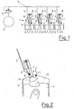
- Fig. 2
- einen Zylinder dieser Brennkraftmaschine.
- Fig. 1
- the internal combustion engine according to the invention and
- Fig. 2
- a cylinder of this internal combustion engine.
Die gasbetriebene Brennkraftmaschine 1 weist einen Hochdruckspeicher 2 für
das Brenngas, welches beispielsweise Erdgas, Wasserstoff, ein Gemisch von
brennbaren Gasen oder dergleichen sein kann, auf. Vom Hochdruckspeicher 2
geht eine Verteilerleitung 3 aus, wobei zwischen Verteilerleitung 3 und Hochdruckspeicher
2 ein Druckregler 4 angeordnet ist, welcher das unter einem Druck
von etwa 200 bar im Hochdruckspeicher 2 gespeicherte Brenngas auf einen Versorgungsdruck
von beispielsweise etwa 6 bar drosselt. Von der Versorgungsleitung
3 geht pro Zylinder 4 mindestens eine Gaszuführleitung 5 aus, welche über
ein Steuerventil 6 in eine Kammer 7 einer Einblaseeinrichtung 8 einmündet. Die
Kammer 7 ist über ein schaltbares Ventil 9, vorzugsweise ein Hubventil, mit dem
Brennraum eines Zylinders 4 verbunden. Das Ventil 9 kann hydraulisch, pneumatisch,
mechanisch oder elektrisch betätigbar sein.The gas-powered
Mit Bezugszeichen 11 ist eine in den Brennraum 10 mündende Zündeinrichtung
bezeichnet.Reference number 11 denotes an ignition device opening into the
Mit Bezugszeichen 14 ist ein im Zylinder 4 hin- und her gehender, eine Kolbenmulde
15 aufweisender Kolben bezeichnet.With
Die Kammer 7 der Einblasevorrichtung 8 dient als Vormischraum und als Gasspeicher.
Das Brenngas wird über das Steuerventil 6 direkt in die Kammer 7 eingeblasen.
Erfolgt die Durchmischung des Brenngases mit dem Brennraum zuvor
entnommenem Gas, so wird durch die Einblasevorrichtung 8 selbst eine relativ
kleine Menge von etwa 6 bis 12 cm3 (Größe der Kammer 7) verdichteten heißen
Gases aus den Brennraum 10 während eines Arbeitszyklus entnommen, indem
das Ventil 9 eine entsprechend lange Zeit nach Beendigung des Einblasevorganges
in den Brennraum 10 offengehalten wird. Dieses dem Brennraum 10 entnommene
Gas wird in der Kammer 7 zwischengespeichert und in das in der
Kammer 7 gespeicherte Gas danach das Brenngas über das Steuerventil 6 eingeblasen.
Im darauf folgenden Zyklus wird das Gemisch aus Brenngas und dem
Brennraum 10 entnommenen Gas in den Brennraum 10 eingeblasen, wodurch
eine Schichtladung 16 im Brennraum 10 erzeugt wird. Das in den Brennraum 10
eingeblasene Gas-Gemisch weist eine lokale Luftzahl zwischen 1 bis 1,7 auf. The
Durch den großen brennbaren mageren Gemischbereich können sowohl die NOx-Emissionen, als auch die Kohlenwasserstoffemissionen entscheidend verringert werden.Due to the large combustible lean mixture area, both the NO x emissions and the hydrocarbon emissions can be significantly reduced.
Claims (6)
Applications Claiming Priority (2)
| Application Number | Priority Date | Filing Date | Title |
|---|---|---|---|
| AT8562002U | 2002-12-19 | ||
| AT0085602U AT7202U1 (en) | 2002-12-19 | 2002-12-19 | METHOD FOR OPERATING A GAS INTERNAL COMBUSTION ENGINE |
Publications (3)
| Publication Number | Publication Date |
|---|---|
| EP1431564A2 true EP1431564A2 (en) | 2004-06-23 |
| EP1431564A3 EP1431564A3 (en) | 2005-05-04 |
| EP1431564B1 EP1431564B1 (en) | 2007-06-13 |
Family
ID=32330365
Family Applications (1)
| Application Number | Title | Priority Date | Filing Date |
|---|---|---|---|
| EP03450272A Expired - Fee Related EP1431564B1 (en) | 2002-12-19 | 2003-12-04 | Method for operating a gaseous fuel operated internal combustion engine |
Country Status (6)
| Country | Link |
|---|---|
| US (1) | US20040149254A1 (en) |
| EP (1) | EP1431564B1 (en) |
| JP (1) | JP2004197751A (en) |
| CN (1) | CN1508409A (en) |
| AT (1) | AT7202U1 (en) |
| DE (1) | DE50307459D1 (en) |
Cited By (6)
| Publication number | Priority date | Publication date | Assignee | Title |
|---|---|---|---|---|
| EP1561940A2 (en) * | 2004-02-06 | 2005-08-10 | Wieslaw Wiatrak | Gas exhaust recirculation assisted fuel injection system |
| WO2009079725A1 (en) | 2007-12-24 | 2009-07-02 | Erwin Erik Paul Georges Vandenberghe | Internal combustion engine and method for adapting an internal combustion engine |
| ITPI20090143A1 (en) * | 2009-11-18 | 2011-05-19 | Univ Pisa | HYDROGEN DIRECT INJECTION SYSTEM FOR AC MOTORS |
| EP2932079A4 (en) * | 2012-12-17 | 2016-09-21 | Westport Power Inc | Air-enriched gaseous fuel direct injection for an internal combustion engine |
| DE102017120512A1 (en) | 2017-09-06 | 2019-03-07 | Keyou GmbH | Method for operating a gas engine, in particular a hydrogen engine, in particular for a motor vehicle |
| AT520481A1 (en) * | 2017-10-02 | 2019-04-15 | Avl List Gmbh | Injection system for a fuel cell system for injecting fuel into a combustion chamber |
Families Citing this family (12)
| Publication number | Priority date | Publication date | Assignee | Title |
|---|---|---|---|---|
| RU2443898C2 (en) * | 2009-10-28 | 2012-02-27 | ГОУ ВПО "Санкт-Петербургский государственный архитектурно-строительный университет" | Engine gas-air mix feed system |
| US8919259B2 (en) | 2012-07-31 | 2014-12-30 | Electro-Motive Diesel, Inc. | Fuel system for consist having daughter locomotive |
| US9073556B2 (en) * | 2012-07-31 | 2015-07-07 | Electro-Motive Diesel, Inc. | Fuel distribution system for multi-locomotive consist |
| US8899158B2 (en) | 2012-07-31 | 2014-12-02 | Electro-Motive Diesel, Inc. | Consist having self-powered tender car |
| US8960100B2 (en) | 2012-07-31 | 2015-02-24 | Electro-Motive Diesel, Inc. | Energy recovery system for a mobile machine |
| US8955444B2 (en) | 2012-07-31 | 2015-02-17 | Electro-Motive Diesel, Inc. | Energy recovery system for a mobile machine |
| US8925465B2 (en) | 2012-07-31 | 2015-01-06 | Electro-Motive Diesel, Inc. | Consist having self-propelled tender car |
| US9193362B2 (en) | 2012-07-31 | 2015-11-24 | Electro-Motive Diesel, Inc. | Consist power system having auxiliary load management |
| JP5846448B2 (en) * | 2012-10-23 | 2016-01-20 | 株式会社デンソー | Pressure control device for gaseous fuel |
| EP2992195B1 (en) * | 2014-01-21 | 2016-09-21 | KREUTER, Peter | Reciprocating piston internal combustion engine, and method for operating a reciprocating piston internal combustion engine |
| CN106796031B (en) | 2014-08-18 | 2022-07-08 | 伍德沃德有限公司 | Torch type igniter |
| US11421601B2 (en) | 2019-03-28 | 2022-08-23 | Woodward, Inc. | Second stage combustion for igniter |
Citations (4)
| Publication number | Priority date | Publication date | Assignee | Title |
|---|---|---|---|---|
| US3703886A (en) * | 1970-11-09 | 1972-11-28 | Julius E Witzky | Pumpless stratified charge gas engine |
| US4865001A (en) * | 1988-11-28 | 1989-09-12 | Energy Conversions, Inc. | Gaseous fuel injector valve |
| EP0798453A1 (en) * | 1996-03-25 | 1997-10-01 | Isuzu Ceramics Research Institute Co., Ltd. | Gas engine with pre-combustion chamber |
| DE19923346A1 (en) * | 1999-02-19 | 2000-08-31 | Dosch Elke | Engine has pressure storage chamber that stores combustion gas when combustion explosions take place, returns gas to combustion chamber(s) before or during next explosion |
Family Cites Families (10)
| Publication number | Priority date | Publication date | Assignee | Title |
|---|---|---|---|---|
| US4574754A (en) * | 1982-08-16 | 1986-03-11 | Rhoades Jr Warren A | Stratified charge combustion system and method for gaseous fuel internal combustion engines |
| US5020494A (en) * | 1987-08-12 | 1991-06-04 | AVL Gesellschaft fur Verbrennungskraftmaschinen und Messtechnik m.b.H. Prof.Dr.Dr.h.c. Hans List | Method and device for feeding fuel into the combustion chamber of an internal combustion engine |
| US4944277A (en) * | 1989-03-03 | 1990-07-31 | Outboard Marine Corporation | Cylinder entrapment system with an air spring |
| US5329908A (en) * | 1993-06-08 | 1994-07-19 | Cummins Engine Company, Inc. | Compressed natural gas injection system for gaseous fueled engines |
| AT408138B (en) * | 1995-02-23 | 2001-09-25 | Avl Verbrennungskraft Messtech | DEVICE FOR INPUTING FUEL INTO THE COMBUSTION CHAMBER OF AN INTERNAL COMBUSTION ENGINE |
| AT408137B (en) * | 1995-02-27 | 2001-09-25 | Avl Verbrennungskraft Messtech | DEVICE FOR INPUTING FUEL INTO THE COMBUSTION CHAMBER OF AN INTERNAL COMBUSTION ENGINE |
| AUPN489595A0 (en) * | 1995-08-18 | 1995-09-14 | Orbital Engine Company (Australia) Proprietary Limited | Gaseous fuel direct injection system for internal combustion engines |
| GB2304811A (en) * | 1995-08-26 | 1997-03-26 | Ford Motor Co | Engine intake fuel atomisation |
| US6298825B1 (en) * | 1998-11-27 | 2001-10-09 | Fev Motorentechnik Gmbh | Method for igniting a multi-cylinder reciprocating gas engine by injecting an ignition gas |
| US6161527A (en) * | 1999-02-11 | 2000-12-19 | Brunswick Corporation | Air assisted direct fuel injection system |
-
2002
- 2002-12-19 AT AT0085602U patent/AT7202U1/en not_active IP Right Cessation
-
2003
- 2003-12-04 EP EP03450272A patent/EP1431564B1/en not_active Expired - Fee Related
- 2003-12-04 DE DE50307459T patent/DE50307459D1/en not_active Expired - Lifetime
- 2003-12-18 US US10/738,211 patent/US20040149254A1/en not_active Abandoned
- 2003-12-19 CN CNA2003101239365A patent/CN1508409A/en active Pending
- 2003-12-19 JP JP2003421750A patent/JP2004197751A/en active Pending
Patent Citations (4)
| Publication number | Priority date | Publication date | Assignee | Title |
|---|---|---|---|---|
| US3703886A (en) * | 1970-11-09 | 1972-11-28 | Julius E Witzky | Pumpless stratified charge gas engine |
| US4865001A (en) * | 1988-11-28 | 1989-09-12 | Energy Conversions, Inc. | Gaseous fuel injector valve |
| EP0798453A1 (en) * | 1996-03-25 | 1997-10-01 | Isuzu Ceramics Research Institute Co., Ltd. | Gas engine with pre-combustion chamber |
| DE19923346A1 (en) * | 1999-02-19 | 2000-08-31 | Dosch Elke | Engine has pressure storage chamber that stores combustion gas when combustion explosions take place, returns gas to combustion chamber(s) before or during next explosion |
Cited By (13)
| Publication number | Priority date | Publication date | Assignee | Title |
|---|---|---|---|---|
| EP1561940A2 (en) * | 2004-02-06 | 2005-08-10 | Wieslaw Wiatrak | Gas exhaust recirculation assisted fuel injection system |
| EP1561940A3 (en) * | 2004-02-09 | 2006-06-28 | Wieslaw Wiatrak | Gas exhaust recirculation assisted fuel injection system |
| WO2009079725A1 (en) | 2007-12-24 | 2009-07-02 | Erwin Erik Paul Georges Vandenberghe | Internal combustion engine and method for adapting an internal combustion engine |
| BE1017913A5 (en) * | 2007-12-24 | 2009-11-03 | Vandenberghe Erwin Erik Paul Georges | INTERNAL COMBUSTION ENGINE. |
| ITPI20090143A1 (en) * | 2009-11-18 | 2011-05-19 | Univ Pisa | HYDROGEN DIRECT INJECTION SYSTEM FOR AC MOTORS |
| US10233871B2 (en) | 2012-12-17 | 2019-03-19 | Westport Power Inc. | Air-enriched gaseous fuel direct injection for an internal combustion engine |
| EP2932079A4 (en) * | 2012-12-17 | 2016-09-21 | Westport Power Inc | Air-enriched gaseous fuel direct injection for an internal combustion engine |
| DE102017120512A1 (en) | 2017-09-06 | 2019-03-07 | Keyou GmbH | Method for operating a gas engine, in particular a hydrogen engine, in particular for a motor vehicle |
| WO2019048454A1 (en) | 2017-09-06 | 2019-03-14 | Keyou GmbH | Method for operating a gas engine |
| US11268460B2 (en) | 2017-09-06 | 2022-03-08 | Keyou GmbH | Method for operating a gas engine |
| DE102017120512B4 (en) | 2017-09-06 | 2022-09-29 | Keyou GmbH | Method of operating a hydrogen engine for a motor vehicle |
| AT520481A1 (en) * | 2017-10-02 | 2019-04-15 | Avl List Gmbh | Injection system for a fuel cell system for injecting fuel into a combustion chamber |
| AT520481B1 (en) * | 2017-10-02 | 2020-03-15 | Avl List Gmbh | Injection system for a fuel cell system for injecting fuel into a combustion chamber |
Also Published As
| Publication number | Publication date |
|---|---|
| DE50307459D1 (en) | 2007-07-26 |
| US20040149254A1 (en) | 2004-08-05 |
| EP1431564A3 (en) | 2005-05-04 |
| EP1431564B1 (en) | 2007-06-13 |
| AT7202U1 (en) | 2004-11-25 |
| CN1508409A (en) | 2004-06-30 |
| JP2004197751A (en) | 2004-07-15 |
Similar Documents
| Publication | Publication Date | Title |
|---|---|---|
| EP1431564A2 (en) | Method for operating a gaseous fuel operated internal combustion engine | |
| DE112007000944B4 (en) | High-performance engines with low emissions, multi-cylinder engines and operating procedures | |
| DE102012107242B4 (en) | Pre-chamber jet igniter and internal combustion engine with a combustion chamber using the same | |
| EP1039112A2 (en) | Fuel supply system for an internal combustion engine with positive ignition | |
| DE2556619A1 (en) | WORKING PROCEDURE FOR AN COMBUSTION ENGINE AND COMBUSTION ENGINE FOR CARRYING OUT THE PROCEDURE | |
| EP1323908A2 (en) | Method for operating an engine | |
| EP1799981A1 (en) | Device and method for the combustion of fuel/air mixtures in an internal combustion engine with pre-chamber ignition | |
| EP3872330A1 (en) | Large diesel engine and method for operating a large diesel engine | |
| DE19945544A1 (en) | Fuel supply system for a spark ignition internal combustion engine and method for operating such an internal combustion engine | |
| EP3896267A1 (en) | Extended longitudinally scavenged motor | |
| EP1585897A2 (en) | Injection unit for an internal combustion engine | |
| DE10307166A1 (en) | Method for operating a spark-ignited internal combustion engine | |
| DE10043384A1 (en) | Fuel metering device for internal combustion engine has controller that regulates amount of fuel injected by injectors in combustion chamber, based on data stored in storage identification field | |
| DE10361665B4 (en) | Gasoline direct injection system | |
| DE10214987B4 (en) | An internal combustion engine and method for generating kinetic energy from hydrocarbonaceous fuels | |
| DE102017201805A1 (en) | Method for injecting an additional medium into the cylinder of a spark-ignited internal combustion engine and internal combustion engine for carrying out such a method | |
| DE102019006486A1 (en) | Method for operating an internal combustion engine, having a main combustion chamber and an antechamber, with gas fuel. | |
| DE102019209232A1 (en) | HPDF operating method for an internal combustion engine, internal combustion engine and working device | |
| DE102022103532B4 (en) | Method for operating an internal combustion engine and corresponding internal combustion engine | |
| DE10328166A1 (en) | Fuel supply system and injection valve for an internal combustion engine | |
| DE612133C (en) | Injection device for crude oil internal combustion engines | |
| DE266426C (en) | ||
| DE553859C (en) | Process for the introduction of pulverulent fuels in internal combustion engines | |
| EP0947689B1 (en) | Method of forming a liquid fuel-air mixture for operating a heat engine | |
| DE10328165A1 (en) | Method for operating a spark-ignited internal combustion engine |
Legal Events
| Date | Code | Title | Description |
|---|---|---|---|
| PUAI | Public reference made under article 153(3) epc to a published international application that has entered the european phase |
Free format text: ORIGINAL CODE: 0009012 |
|
| AK | Designated contracting states |
Kind code of ref document: A2 Designated state(s): AT BE BG CH CY CZ DE DK EE ES FI FR GB GR HU IE IT LI LU MC NL PT RO SE SI SK TR |
|
| AX | Request for extension of the european patent |
Extension state: AL LT LV MK |
|
| PUAL | Search report despatched |
Free format text: ORIGINAL CODE: 0009013 |
|
| AK | Designated contracting states |
Kind code of ref document: A3 Designated state(s): AT BE BG CH CY CZ DE DK EE ES FI FR GB GR HU IE IT LI LU MC NL PT RO SE SI SK TR |
|
| AX | Request for extension of the european patent |
Extension state: AL LT LV MK |
|
| RIC1 | Information provided on ipc code assigned before grant |
Ipc: 7F 02B 17/00 B Ipc: 7F 02B 43/04 B Ipc: 7F 02M 21/02 A |
|
| 17P | Request for examination filed |
Effective date: 20051022 |
|
| AKX | Designation fees paid |
Designated state(s): DE FR IT |
|
| GRAP | Despatch of communication of intention to grant a patent |
Free format text: ORIGINAL CODE: EPIDOSNIGR1 |
|
| GRAS | Grant fee paid |
Free format text: ORIGINAL CODE: EPIDOSNIGR3 |
|
| GRAA | (expected) grant |
Free format text: ORIGINAL CODE: 0009210 |
|
| AK | Designated contracting states |
Kind code of ref document: B1 Designated state(s): DE FR IT |
|
| REF | Corresponds to: |
Ref document number: 50307459 Country of ref document: DE Date of ref document: 20070726 Kind code of ref document: P |
|
| ET | Fr: translation filed | ||
| PLBE | No opposition filed within time limit |
Free format text: ORIGINAL CODE: 0009261 |
|
| STAA | Information on the status of an ep patent application or granted ep patent |
Free format text: STATUS: NO OPPOSITION FILED WITHIN TIME LIMIT |
|
| 26N | No opposition filed |
Effective date: 20080314 |
|
| PGFP | Annual fee paid to national office [announced via postgrant information from national office to epo] |
Ref country code: IT Payment date: 20101229 Year of fee payment: 8 Ref country code: DE Payment date: 20101201 Year of fee payment: 8 |
|
| PGFP | Annual fee paid to national office [announced via postgrant information from national office to epo] |
Ref country code: FR Payment date: 20111223 Year of fee payment: 9 |
|
| REG | Reference to a national code |
Ref country code: FR Ref legal event code: ST Effective date: 20130830 |
|
| REG | Reference to a national code |
Ref country code: DE Ref legal event code: R119 Ref document number: 50307459 Country of ref document: DE Effective date: 20130702 |
|
| PG25 | Lapsed in a contracting state [announced via postgrant information from national office to epo] |
Ref country code: DE Free format text: LAPSE BECAUSE OF NON-PAYMENT OF DUE FEES Effective date: 20130702 |
|
| PG25 | Lapsed in a contracting state [announced via postgrant information from national office to epo] |
Ref country code: FR Free format text: LAPSE BECAUSE OF NON-PAYMENT OF DUE FEES Effective date: 20130102 |
|
| PG25 | Lapsed in a contracting state [announced via postgrant information from national office to epo] |
Ref country code: IT Free format text: LAPSE BECAUSE OF NON-PAYMENT OF DUE FEES Effective date: 20121204 |