EP1443880B1 - Intra-aortic balloon counterpulsation with concurrent hypothermia - Google Patents
Intra-aortic balloon counterpulsation with concurrent hypothermia Download PDFInfo
- Publication number
- EP1443880B1 EP1443880B1 EP02780480A EP02780480A EP1443880B1 EP 1443880 B1 EP1443880 B1 EP 1443880B1 EP 02780480 A EP02780480 A EP 02780480A EP 02780480 A EP02780480 A EP 02780480A EP 1443880 B1 EP1443880 B1 EP 1443880B1
- Authority
- EP
- European Patent Office
- Prior art keywords
- balloon
- counterpulsation
- heat exchanger
- heat exchange
- catheter
- Prior art date
- Legal status (The legal status is an assumption and is not a legal conclusion. Google has not performed a legal analysis and makes no representation as to the accuracy of the status listed.)
- Expired - Lifetime
Links
- 230000002631 hypothermal effect Effects 0.000 title abstract description 16
- 210000000709 aorta Anatomy 0.000 claims abstract description 22
- 238000001816 cooling Methods 0.000 claims abstract description 12
- 230000000747 cardiac effect Effects 0.000 claims abstract description 8
- 230000000694 effects Effects 0.000 claims abstract description 8
- 239000012530 fluid Substances 0.000 claims description 21
- 239000008280 blood Substances 0.000 claims description 17
- 210000004369 blood Anatomy 0.000 claims description 17
- 230000004044 response Effects 0.000 claims description 11
- 230000017531 blood circulation Effects 0.000 claims description 8
- 230000037000 normothermia Effects 0.000 claims 2
- 230000009286 beneficial effect Effects 0.000 claims 1
- 230000002708 enhancing effect Effects 0.000 claims 1
- 238000000034 method Methods 0.000 abstract description 12
- 238000010438 heat treatment Methods 0.000 abstract description 3
- 230000010412 perfusion Effects 0.000 abstract description 3
- 210000005166 vasculature Anatomy 0.000 abstract description 3
- 208000009378 Low Cardiac Output Diseases 0.000 abstract 1
- 208000037265 diseases, disorders, signs and symptoms Diseases 0.000 abstract 1
- 238000003780 insertion Methods 0.000 abstract 1
- 230000037431 insertion Effects 0.000 abstract 1
- 206010008531 Chills Diseases 0.000 description 20
- 238000011282 treatment Methods 0.000 description 9
- 210000002376 aorta thoracic Anatomy 0.000 description 8
- 239000003795 chemical substances by application Substances 0.000 description 8
- 210000004165 myocardium Anatomy 0.000 description 8
- 230000006870 function Effects 0.000 description 7
- XADCESSVHJOZHK-UHFFFAOYSA-N Meperidine Chemical compound C=1C=CC=CC=1C1(C(=O)OCC)CCN(C)CC1 XADCESSVHJOZHK-UHFFFAOYSA-N 0.000 description 6
- 210000002168 brachiocephalic trunk Anatomy 0.000 description 6
- 210000004351 coronary vessel Anatomy 0.000 description 6
- 229960000482 pethidine Drugs 0.000 description 6
- 210000003270 subclavian artery Anatomy 0.000 description 6
- 210000004204 blood vessel Anatomy 0.000 description 5
- 210000001168 carotid artery common Anatomy 0.000 description 5
- 230000001965 increasing effect Effects 0.000 description 5
- 230000002503 metabolic effect Effects 0.000 description 5
- CURLTUGMZLYLDI-UHFFFAOYSA-N Carbon dioxide Chemical compound O=C=O CURLTUGMZLYLDI-UHFFFAOYSA-N 0.000 description 4
- 238000010586 diagram Methods 0.000 description 4
- 239000007789 gas Substances 0.000 description 4
- 230000002093 peripheral effect Effects 0.000 description 4
- FAPWRFPIFSIZLT-UHFFFAOYSA-M Sodium chloride Chemical compound [Na+].[Cl-] FAPWRFPIFSIZLT-UHFFFAOYSA-M 0.000 description 3
- 210000001124 body fluid Anatomy 0.000 description 3
- 239000010839 body fluid Substances 0.000 description 3
- 230000001939 inductive effect Effects 0.000 description 3
- 238000001990 intravenous administration Methods 0.000 description 3
- 230000002829 reductive effect Effects 0.000 description 3
- 230000009885 systemic effect Effects 0.000 description 3
- 206010019280 Heart failures Diseases 0.000 description 2
- 241000282412 Homo Species 0.000 description 2
- 210000004556 brain Anatomy 0.000 description 2
- 229910002092 carbon dioxide Inorganic materials 0.000 description 2
- 239000001569 carbon dioxide Substances 0.000 description 2
- 230000001010 compromised effect Effects 0.000 description 2
- 230000007423 decrease Effects 0.000 description 2
- 230000003247 decreasing effect Effects 0.000 description 2
- 229940079593 drug Drugs 0.000 description 2
- 239000003814 drug Substances 0.000 description 2
- 210000001105 femoral artery Anatomy 0.000 description 2
- 230000004217 heart function Effects 0.000 description 2
- 239000001307 helium Substances 0.000 description 2
- 229910052734 helium Inorganic materials 0.000 description 2
- SWQJXJOGLNCZEY-UHFFFAOYSA-N helium atom Chemical compound [He] SWQJXJOGLNCZEY-UHFFFAOYSA-N 0.000 description 2
- 210000005240 left ventricle Anatomy 0.000 description 2
- 238000012544 monitoring process Methods 0.000 description 2
- 230000008569 process Effects 0.000 description 2
- 238000005086 pumping Methods 0.000 description 2
- 239000000523 sample Substances 0.000 description 2
- QZAYGJVTTNCVMB-UHFFFAOYSA-N serotonin Chemical compound C1=C(O)C=C2C(CCN)=CNC2=C1 QZAYGJVTTNCVMB-UHFFFAOYSA-N 0.000 description 2
- 230000003068 static effect Effects 0.000 description 2
- 238000010792 warming Methods 0.000 description 2
- 102100022738 5-hydroxytryptamine receptor 1A Human genes 0.000 description 1
- 101710138638 5-hydroxytryptamine receptor 1A Proteins 0.000 description 1
- 241000237519 Bivalvia Species 0.000 description 1
- GJSURZIOUXUGAL-UHFFFAOYSA-N Clonidine Chemical compound ClC1=CC=CC(Cl)=C1NC1=NCCN1 GJSURZIOUXUGAL-UHFFFAOYSA-N 0.000 description 1
- 206010028980 Neoplasm Diseases 0.000 description 1
- 229940121954 Opioid receptor agonist Drugs 0.000 description 1
- 239000012190 activator Substances 0.000 description 1
- 239000000695 adrenergic alpha-agonist Substances 0.000 description 1
- 238000013459 approach Methods 0.000 description 1
- 210000001367 artery Anatomy 0.000 description 1
- QVGXLLKOCUKJST-UHFFFAOYSA-N atomic oxygen Chemical compound [O] QVGXLLKOCUKJST-UHFFFAOYSA-N 0.000 description 1
- 230000008901 benefit Effects 0.000 description 1
- 230000005540 biological transmission Effects 0.000 description 1
- 230000000903 blocking effect Effects 0.000 description 1
- 230000036770 blood supply Effects 0.000 description 1
- 230000036760 body temperature Effects 0.000 description 1
- 230000009172 bursting Effects 0.000 description 1
- QWCRAEMEVRGPNT-UHFFFAOYSA-N buspirone Chemical compound C1C(=O)N(CCCCN2CCN(CC2)C=2N=CC=CN=2)C(=O)CC21CCCC2 QWCRAEMEVRGPNT-UHFFFAOYSA-N 0.000 description 1
- 229960002495 buspirone Drugs 0.000 description 1
- 210000000748 cardiovascular system Anatomy 0.000 description 1
- 230000002490 cerebral effect Effects 0.000 description 1
- 235000020639 clam Nutrition 0.000 description 1
- 229960002896 clonidine Drugs 0.000 description 1
- 230000002301 combined effect Effects 0.000 description 1
- 230000008867 communication pathway Effects 0.000 description 1
- 230000008602 contraction Effects 0.000 description 1
- 230000036757 core body temperature Effects 0.000 description 1
- HRLIOXLXPOHXTA-NSHDSACASA-N dexmedetomidine Chemical compound C1([C@@H](C)C=2C(=C(C)C=CC=2)C)=CN=C[N]1 HRLIOXLXPOHXTA-NSHDSACASA-N 0.000 description 1
- 229960004253 dexmedetomidine Drugs 0.000 description 1
- 210000003238 esophagus Anatomy 0.000 description 1
- 208000014674 injury Diseases 0.000 description 1
- 230000000670 limiting effect Effects 0.000 description 1
- 230000007246 mechanism Effects 0.000 description 1
- 210000001363 mesenteric artery superior Anatomy 0.000 description 1
- 239000002184 metal Substances 0.000 description 1
- 238000012986 modification Methods 0.000 description 1
- 230000004048 modification Effects 0.000 description 1
- 239000002756 mu opiate receptor agonist Substances 0.000 description 1
- 229940126487 mu opioid receptor agonist Drugs 0.000 description 1
- 230000002107 myocardial effect Effects 0.000 description 1
- 239000003402 opiate agonist Substances 0.000 description 1
- 239000001301 oxygen Substances 0.000 description 1
- 229910052760 oxygen Inorganic materials 0.000 description 1
- 238000012545 processing Methods 0.000 description 1
- 229940044601 receptor agonist Drugs 0.000 description 1
- 239000000018 receptor agonist Substances 0.000 description 1
- 230000009467 reduction Effects 0.000 description 1
- 210000002254 renal artery Anatomy 0.000 description 1
- 229940076279 serotonin Drugs 0.000 description 1
- 239000000126 substance Substances 0.000 description 1
- 238000001356 surgical procedure Methods 0.000 description 1
- 230000032258 transport Effects 0.000 description 1
- 230000008733 trauma Effects 0.000 description 1
- 230000007306 turnover Effects 0.000 description 1
- 210000003462 vein Anatomy 0.000 description 1
- 210000001631 vena cava inferior Anatomy 0.000 description 1
- 239000002699 waste material Substances 0.000 description 1
Images


Classifications
-
- A—HUMAN NECESSITIES
- A61—MEDICAL OR VETERINARY SCIENCE; HYGIENE
- A61F—FILTERS IMPLANTABLE INTO BLOOD VESSELS; PROSTHESES; DEVICES PROVIDING PATENCY TO, OR PREVENTING COLLAPSING OF, TUBULAR STRUCTURES OF THE BODY, e.g. STENTS; ORTHOPAEDIC, NURSING OR CONTRACEPTIVE DEVICES; FOMENTATION; TREATMENT OR PROTECTION OF EYES OR EARS; BANDAGES, DRESSINGS OR ABSORBENT PADS; FIRST-AID KITS
- A61F7/00—Heating or cooling appliances for medical or therapeutic treatment of the human body
- A61F7/12—Devices for heating or cooling internal body cavities
- A61F7/123—Devices for heating or cooling internal body cavities using a flexible balloon containing the thermal element
-
- A—HUMAN NECESSITIES
- A61—MEDICAL OR VETERINARY SCIENCE; HYGIENE
- A61M—DEVICES FOR INTRODUCING MEDIA INTO, OR ONTO, THE BODY; DEVICES FOR TRANSDUCING BODY MEDIA OR FOR TAKING MEDIA FROM THE BODY; DEVICES FOR PRODUCING OR ENDING SLEEP OR STUPOR
- A61M60/00—Blood pumps; Devices for mechanical circulatory actuation; Balloon pumps for circulatory assistance
- A61M60/10—Location thereof with respect to the patient's body
- A61M60/122—Implantable pumps or pumping devices, i.e. the blood being pumped inside the patient's body
- A61M60/126—Implantable pumps or pumping devices, i.e. the blood being pumped inside the patient's body implantable via, into, inside, in line, branching on, or around a blood vessel
- A61M60/135—Implantable pumps or pumping devices, i.e. the blood being pumped inside the patient's body implantable via, into, inside, in line, branching on, or around a blood vessel inside a blood vessel, e.g. using grafting
- A61M60/139—Implantable pumps or pumping devices, i.e. the blood being pumped inside the patient's body implantable via, into, inside, in line, branching on, or around a blood vessel inside a blood vessel, e.g. using grafting inside the aorta, e.g. intra-aortic balloon pumps
-
- A—HUMAN NECESSITIES
- A61—MEDICAL OR VETERINARY SCIENCE; HYGIENE
- A61M—DEVICES FOR INTRODUCING MEDIA INTO, OR ONTO, THE BODY; DEVICES FOR TRANSDUCING BODY MEDIA OR FOR TAKING MEDIA FROM THE BODY; DEVICES FOR PRODUCING OR ENDING SLEEP OR STUPOR
- A61M60/00—Blood pumps; Devices for mechanical circulatory actuation; Balloon pumps for circulatory assistance
- A61M60/20—Type thereof
- A61M60/295—Balloon pumps for circulatory assistance
-
- A—HUMAN NECESSITIES
- A61—MEDICAL OR VETERINARY SCIENCE; HYGIENE
- A61M—DEVICES FOR INTRODUCING MEDIA INTO, OR ONTO, THE BODY; DEVICES FOR TRANSDUCING BODY MEDIA OR FOR TAKING MEDIA FROM THE BODY; DEVICES FOR PRODUCING OR ENDING SLEEP OR STUPOR
- A61M60/00—Blood pumps; Devices for mechanical circulatory actuation; Balloon pumps for circulatory assistance
- A61M60/30—Medical purposes thereof other than the enhancement of the cardiac output
- A61M60/36—Medical purposes thereof other than the enhancement of the cardiac output for specific blood treatment; for specific therapy
-
- A—HUMAN NECESSITIES
- A61—MEDICAL OR VETERINARY SCIENCE; HYGIENE
- A61M—DEVICES FOR INTRODUCING MEDIA INTO, OR ONTO, THE BODY; DEVICES FOR TRANSDUCING BODY MEDIA OR FOR TAKING MEDIA FROM THE BODY; DEVICES FOR PRODUCING OR ENDING SLEEP OR STUPOR
- A61M60/00—Blood pumps; Devices for mechanical circulatory actuation; Balloon pumps for circulatory assistance
- A61M60/40—Details relating to driving
- A61M60/497—Details relating to driving for balloon pumps for circulatory assistance
-
- A—HUMAN NECESSITIES
- A61—MEDICAL OR VETERINARY SCIENCE; HYGIENE
- A61M—DEVICES FOR INTRODUCING MEDIA INTO, OR ONTO, THE BODY; DEVICES FOR TRANSDUCING BODY MEDIA OR FOR TAKING MEDIA FROM THE BODY; DEVICES FOR PRODUCING OR ENDING SLEEP OR STUPOR
- A61M60/00—Blood pumps; Devices for mechanical circulatory actuation; Balloon pumps for circulatory assistance
- A61M60/50—Details relating to control
- A61M60/508—Electronic control means, e.g. for feedback regulation
-
- A—HUMAN NECESSITIES
- A61—MEDICAL OR VETERINARY SCIENCE; HYGIENE
- A61M—DEVICES FOR INTRODUCING MEDIA INTO, OR ONTO, THE BODY; DEVICES FOR TRANSDUCING BODY MEDIA OR FOR TAKING MEDIA FROM THE BODY; DEVICES FOR PRODUCING OR ENDING SLEEP OR STUPOR
- A61M60/00—Blood pumps; Devices for mechanical circulatory actuation; Balloon pumps for circulatory assistance
- A61M60/80—Constructional details other than related to driving
- A61M60/841—Constructional details other than related to driving of balloon pumps for circulatory assistance
- A61M60/843—Balloon aspects, e.g. shapes or materials
-
- A—HUMAN NECESSITIES
- A61—MEDICAL OR VETERINARY SCIENCE; HYGIENE
- A61M—DEVICES FOR INTRODUCING MEDIA INTO, OR ONTO, THE BODY; DEVICES FOR TRANSDUCING BODY MEDIA OR FOR TAKING MEDIA FROM THE BODY; DEVICES FOR PRODUCING OR ENDING SLEEP OR STUPOR
- A61M60/00—Blood pumps; Devices for mechanical circulatory actuation; Balloon pumps for circulatory assistance
- A61M60/80—Constructional details other than related to driving
- A61M60/855—Constructional details other than related to driving of implantable pumps or pumping devices
- A61M60/884—Constructional details other than related to driving of implantable pumps or pumping devices being associated to additional implantable blood treating devices
-
- A—HUMAN NECESSITIES
- A61—MEDICAL OR VETERINARY SCIENCE; HYGIENE
- A61F—FILTERS IMPLANTABLE INTO BLOOD VESSELS; PROSTHESES; DEVICES PROVIDING PATENCY TO, OR PREVENTING COLLAPSING OF, TUBULAR STRUCTURES OF THE BODY, e.g. STENTS; ORTHOPAEDIC, NURSING OR CONTRACEPTIVE DEVICES; FOMENTATION; TREATMENT OR PROTECTION OF EYES OR EARS; BANDAGES, DRESSINGS OR ABSORBENT PADS; FIRST-AID KITS
- A61F7/00—Heating or cooling appliances for medical or therapeutic treatment of the human body
- A61F2007/0054—Heating or cooling appliances for medical or therapeutic treatment of the human body with a closed fluid circuit, e.g. hot water
- A61F2007/0056—Heating or cooling appliances for medical or therapeutic treatment of the human body with a closed fluid circuit, e.g. hot water for cooling
-
- A—HUMAN NECESSITIES
- A61—MEDICAL OR VETERINARY SCIENCE; HYGIENE
- A61F—FILTERS IMPLANTABLE INTO BLOOD VESSELS; PROSTHESES; DEVICES PROVIDING PATENCY TO, OR PREVENTING COLLAPSING OF, TUBULAR STRUCTURES OF THE BODY, e.g. STENTS; ORTHOPAEDIC, NURSING OR CONTRACEPTIVE DEVICES; FOMENTATION; TREATMENT OR PROTECTION OF EYES OR EARS; BANDAGES, DRESSINGS OR ABSORBENT PADS; FIRST-AID KITS
- A61F7/00—Heating or cooling appliances for medical or therapeutic treatment of the human body
- A61F2007/0095—Heating or cooling appliances for medical or therapeutic treatment of the human body with a temperature indicator
-
- A—HUMAN NECESSITIES
- A61—MEDICAL OR VETERINARY SCIENCE; HYGIENE
- A61F—FILTERS IMPLANTABLE INTO BLOOD VESSELS; PROSTHESES; DEVICES PROVIDING PATENCY TO, OR PREVENTING COLLAPSING OF, TUBULAR STRUCTURES OF THE BODY, e.g. STENTS; ORTHOPAEDIC, NURSING OR CONTRACEPTIVE DEVICES; FOMENTATION; TREATMENT OR PROTECTION OF EYES OR EARS; BANDAGES, DRESSINGS OR ABSORBENT PADS; FIRST-AID KITS
- A61F7/00—Heating or cooling appliances for medical or therapeutic treatment of the human body
- A61F7/12—Devices for heating or cooling internal body cavities
- A61F2007/126—Devices for heating or cooling internal body cavities for invasive application, e.g. for introducing into blood vessels
-
- A—HUMAN NECESSITIES
- A61—MEDICAL OR VETERINARY SCIENCE; HYGIENE
- A61F—FILTERS IMPLANTABLE INTO BLOOD VESSELS; PROSTHESES; DEVICES PROVIDING PATENCY TO, OR PREVENTING COLLAPSING OF, TUBULAR STRUCTURES OF THE BODY, e.g. STENTS; ORTHOPAEDIC, NURSING OR CONTRACEPTIVE DEVICES; FOMENTATION; TREATMENT OR PROTECTION OF EYES OR EARS; BANDAGES, DRESSINGS OR ABSORBENT PADS; FIRST-AID KITS
- A61F7/00—Heating or cooling appliances for medical or therapeutic treatment of the human body
- A61F7/10—Cooling bags, e.g. ice-bags
-
- A—HUMAN NECESSITIES
- A61—MEDICAL OR VETERINARY SCIENCE; HYGIENE
- A61M—DEVICES FOR INTRODUCING MEDIA INTO, OR ONTO, THE BODY; DEVICES FOR TRANSDUCING BODY MEDIA OR FOR TAKING MEDIA FROM THE BODY; DEVICES FOR PRODUCING OR ENDING SLEEP OR STUPOR
- A61M19/00—Local anaesthesia; Hypothermia
-
- A—HUMAN NECESSITIES
- A61—MEDICAL OR VETERINARY SCIENCE; HYGIENE
- A61M—DEVICES FOR INTRODUCING MEDIA INTO, OR ONTO, THE BODY; DEVICES FOR TRANSDUCING BODY MEDIA OR FOR TAKING MEDIA FROM THE BODY; DEVICES FOR PRODUCING OR ENDING SLEEP OR STUPOR
- A61M2205/00—General characteristics of the apparatus
- A61M2205/36—General characteristics of the apparatus related to heating or cooling
- A61M2205/3606—General characteristics of the apparatus related to heating or cooling cooled
-
- A—HUMAN NECESSITIES
- A61—MEDICAL OR VETERINARY SCIENCE; HYGIENE
- A61M—DEVICES FOR INTRODUCING MEDIA INTO, OR ONTO, THE BODY; DEVICES FOR TRANSDUCING BODY MEDIA OR FOR TAKING MEDIA FROM THE BODY; DEVICES FOR PRODUCING OR ENDING SLEEP OR STUPOR
- A61M2230/00—Measuring parameters of the user
- A61M2230/04—Heartbeat characteristics, e.g. ECG, blood pressure modulation
-
- A—HUMAN NECESSITIES
- A61—MEDICAL OR VETERINARY SCIENCE; HYGIENE
- A61M—DEVICES FOR INTRODUCING MEDIA INTO, OR ONTO, THE BODY; DEVICES FOR TRANSDUCING BODY MEDIA OR FOR TAKING MEDIA FROM THE BODY; DEVICES FOR PRODUCING OR ENDING SLEEP OR STUPOR
- A61M60/00—Blood pumps; Devices for mechanical circulatory actuation; Balloon pumps for circulatory assistance
- A61M60/20—Type thereof
- A61M60/247—Positive displacement blood pumps
- A61M60/253—Positive displacement blood pumps including a displacement member directly acting on the blood
- A61M60/268—Positive displacement blood pumps including a displacement member directly acting on the blood the displacement member being flexible, e.g. membranes, diaphragms or bladders
- A61M60/274—Positive displacement blood pumps including a displacement member directly acting on the blood the displacement member being flexible, e.g. membranes, diaphragms or bladders the inlet and outlet being the same, e.g. para-aortic counter-pulsation blood pumps
Definitions
- This invention relates generally to apparatus for medical treatment and more particularly to devices and systems for administering intra-aortic balloon counterpulsation concurrently with the use of a heat exchange catheter for inducing and maintaining hypothermia in at least a portion of the patient's body (e.g., cardiac hypothermia, cardiac & cerebral hypothermia, etc.)
- a heat exchange catheter for inducing and maintaining hypothermia in at least a portion of the patient's body (e.g., cardiac hypothermia, cardiac & cerebral hypothermia, etc.)
- An intra-aortic balloon pump is a device that may be used to a) increase myocardial blood flow in patients whose cardiac output is compromised due to heart failure or cardiac insufficiency and b) decreases the heart's workload, through a process called counterpulsation.
- the human heart expels oxygenated blood into the aorta as its left ventricle contracts (i.e., during systole) and, thereafter, receives a backflow of arterial blood into the coronary arteries as its left ventricle relaxes (i.e., during diastole).
- the systolic pumping of blood into the aorta requires the heart muscle to overcome the static pressure of blood that is already in the aorta.
- a healthy heart is typically able to perform both of these functions effectively.
- a weakened or failing heart may be unable to perform the work required to fully overcome the static pressure of blood already in the aorta, thereby resulting in less ejection of oxygenated blood into the aorta during systole and less backflow of oxygenated blood into the coronary arteries during diastole.
- Intra-aortic balloon counterpulsation is a technique which causes more arterial blood to enter the coronary arteries (and thus more blood flow to the heart muscle) during diastole (less flow work) and decreases the amount of work that the heart must perform during systole (less pressure work).
- the myocardium receives more oxygen, thereby allowing the heart to pump more effectively and increasing the cardiac output that occurs with each heartbeat (i.e., the "stroke volume").
- the IABP comprises a) a balloon catheter that is percutaneously insertable into the patient's aorta and b) a control console that is attached to the balloon catheter.
- a computer or controller within the control console receives the patient's electrocardiogram (ECG).
- ECG electrocardiogram
- the controller causes the intra-aortic balloon to be inflated during diastole (when the heart muscle relaxed) resulting in increased back pressure within the aorta and increased blood flow into the coronary arteries, and deflated during early systole (during a phase known as "isometric contraction") resulting in a reduction of intra-aortic pressure against which the heart must pump.
- IABP improves blood flow to the heart muscle and reduces the workload of the heart muscle. Additionally, IABP counterpulsation has been demonstrated to improve peripheral or systemic arterial perfusion. Although the mechanism by which IABP counterpulsation improves peripheral or systemic profusion is not well understood, it is believed that inflation of the intra-aortic balloon during diastole serves to facilitate peripheral runoff (sometimes referred to as the intrinsic "Windkessel" effect) which then augments peripheral perfusion.
- the gas used to inflate the balloon is either carbon dioxide (which has fewer consequences in the rare event of a balloon bursting) or helium (which has the fastest ability to travel or diffuse).
- Mild hypothermia has been shown to both increase the contractility of the heart muscle and to reduce its metabolic requirements. Indeed, if the hypothermia is systemic, the metabolic demands of the entire body are generally reduced, so that the demands placed on the heart may be reduced. Additionally, when the patient's body temperature is reduced and maintained 1°C or more below normothermic (e.g., less than 36°C in most individuals), such that the output of the heart increases, the condition and function of the heart muscle may improve significantly due to the combined effects of increased bloodflow to the heart, a temporarily decreased metabolic need and decreased metabolic waste products.
- normothermic e.g., less than 36°C in most individuals
- the potential for shivering is present whenever a patient is cooled below that patients shivering threshold, which in humans is generally about 35.5°C.
- patients shivering threshold which in humans is generally about 35.5°C.
- hypothermia When inducing hypothermia below the shivering threshold, it is very important to avoid or limit the shivering response. The avoidance or limiting of the shivering response may be particularly important in patients who suffer from compromised cardiac function and/or metabolic irregularities.
- An anti-shivering treatment may be administered to prevent or deter shivering. Examples of effective anti-shivering treatments are described in United States Patent No. 6,231,594 (Dae et al. ).
- United States Patent No. 6, 299, 599 (Pham et al. ) describes a system for controlling patient temperature wherein a central venous line catheter having axially spaced distal and proximal heat exchange balloons is inserted into a blood vessel.
- the central venous line catheter is provided with one or more lumens for providing access to the central blood supply of the patient, and with additional lumens for communicating heat exchange fluid to the balloons.
- Heat exchange fluid temperature is controlled through a feed back loop in which patient temperature is sensed and used to control a temperature control unit comprising a heating device and/or a cooling device in heat exchange relationship with the heat exchange fluid.
- a tubing set transports the heat exchange fluid between the central venous line and the temperature control unit, with a pump serving to circulate the fluid in a closed fluid circuit in the system.
- the system described by Pham et al. does not include any intraortic counterpulsation balloon or any other apparatus for intra-aortic counterpulsation.
- United States Patent No. 6,126,684 (Gobin et al. ) describes a catheter that is used to exchange heat with a body fluid, such as blood, flowing in a body conduit, such as a blood vessel.
- the catheter includes a shaft with a heat exchange region disposed at its distal end. This region may include at least one balloon which is adapted to receive a remotely cooled heat exchange fluid preferably flowing in a direction counter to that of the body fluid.
- Embodiments including multiple balloons enhance the surface area of contact, and the mixing of both the heat exchange and the body fluid.
- the catheter can be positioned to produce hypothermia in a selective area of the body without cooling the entire body system.
- the present invention provides a catheter device that is insertable into the aorta of a human or veterinary patient.
- catheter device comprises a) a balloon that is useable for performing intra-aortic counterpulsation and b) a heat exchanger for exchanging heat with the patient's flowing blood so as to induce hypothermia of all or a portion of the patient's body.
- the catheter device of the foregoing character may be used in combination with driving and control apparatus connected to the catheter for a) causing and controlling the inflation/deflation of the intra-aortic balloon and b) cool or warming the heat exchanger to bring about and maintain the desired hypothermia of all or a portion of the patient's body.
- the driving and control apparatus may be positioned extracorporeally and may be housed in one or more consoles that are positioned near the patent's bed.
- at least the patient's heart (and in some cases the brain, other portions of the body or the entire body) will be maintained at a temperature 1 °C or more below normothermic (e.g., less than 36°C in most humans).
- the heat exchanger of the catheter device may comprise less than the entire length of the catheter.
- the heat exchanger of the catheter may comprise or be associated with one or more flow-disrupting surface(s) which increase the effective heat exchange surface area and/or alter or disrupt the laminarity of blood flow adjacent to the heat exchanger in a manner that causes some turn over of blood within heat exchange proximity to the heat exchanger and a resultant increase in the efficiency of the heat exchange process.
- the heat exchanger of the catheter may be of a flowing fluid type, wherein a fluidic heat exchange medium (e.g., saline solution) is circulated through the catheter and through the heat exchanger.
- a fluidic heat exchange medium e.g., saline solution
- such flowing fluid type heat exchanger may comprise a flexible structure (e.g., a balloon) which expands or become taut when the heat exchange fluid is circulated therethrough.
- the heat exchange balloon may be multi-lobed and/or may be curved or twisted (e.g., helical) in configuration.
- a wall or surface which separates the patient's flowing blood from the heat exchange medium being circulated through the heat exchanger may comprise a metal to provide for provide for improved heat transmission between the blood and the heat exchange medium.
- the heat exchanger and the counterpulsation balloon may comprise one in the same structure.
- the counterpulsation balloon may be inflated and deflated with a cold gas such that the counterpulsation balloon itself serves as a heat exchanger (in addition to performing its counterpulsation function).
- a channel or space for recirculation of heat exchange medium e.g., cooled saline solution
- heat exchange medium may be formed on or in a wall or portion of the counterpulsation balloon such that heat exchange medium is circulated therethrough as the counterpulsation balloon undergoes repeated inflation and deflation.
- the heat exchanger may be located more distally on the catheter than the counterpulsation balloon, such that when the catheter is advanced in retrograde fashion into the patient's aorta to a position where the counterpulsation balloon is properly positioned to perform its counterpulsation function (e.g., within the thoracic aorta), the heat exchanger will be positioned superior to the counterpulsation balloon (e.g., within the aorta between the heart and the counterpulsation balloon).
- the heat exchanger may be located more proximally on the catheter than the counterpulsation balloon, such that when the catheter is advanced in retrograde fashion into the patient's aorta to a position where the counterpulsation balloon is properly positioned to perform its counterputsation function (e.g., within the thoracic aorta), the heat exchanger will be located inferior to the counterpulsation balloon (e.g., within the aorta between the counterpulsation balloon and the iliac bifurcation.
- the method may be carried out using separate intra-aortic balloon counterpulsation catheter and heat exchange catheters.
- the heat exchange catheter is separate from the intra-aortic balloon counterpulsation catheter and thus need not necessarily be positioned in the aorta along with the intra-aortic balloon counterpulsation catheter. Rather, the separate heat exchange catheter may be positioned in any suitable blood vessel (vein or artery) to effect cooling of the desired portion of the patient's body and/or the entire patient's body. Examples of separate heat exchange catheters and related control systems are described in United States Patent Nos. 5,486,208 (Ginsburg ), 8264,679 (Keller et al.
- the method may further comprise the step of administering to the patient an anti-shivering treatment such as those described in United States Patent No. 6,231,594 (Dae et al. )
- a balloon/heat exchanger catheter 10, 10a, 10b of the present invention generally comprises an elongate catheter body 12, 12a, 12b having a heat exchanger 16, 16a, 16b and a counterpulsation balloon 14, 14a, 14b positioned thereon.
- the catheter body 12, 12a, 12b proximal to the heat exchanger 16, 16a, 16b comprises a gas inflation/deflation lumen 52 through which gas or other suitable fluid is alternately infused and withdrawn to effect inflation and deflation of the counterpulsation balloon 14, 14a, 14b as well as heat exchange fluid inflow and outflow lumens 54, 56 through which heat exchange fluid is circulated through the heat exchanger 16, 16a, 16b.
- the heat exchange fluid inflow lumen 54 is connected to the proximal end of the heat exchanger 16, 16a, 16b and the heat exchange fluid outflow lumen 56 is connected to the distal end of the heat exchanger 16, 16a, 16b, thereby causing the heat exchange fluid to flow through the heat exchanger 16, 16a, 16b in a direction opposite the direction in which blood is flowing through the patient's aorta.
- the counterpulsation balloon 14 may be positioned on a portion of the catheter body 12 that is distal to the heat exchanger 16.
- the counterpulsation balloon 14a, 14b may be positioned on a portion of the catheter body that is proximal to the heat exchanger 16a, 16b.
- hybrids or combinations of these designs may also be employed wherein one or more heat exchangers may be positioned proximal and distal to the counterpulsation balloon.
- the catheter body 12, 12a, 12b has multiple lumens as needed to permit the passage of balloon inflation fluid (e.g., carbon dioxide or helium) into and out of the counterpulsation balloon 14, 14a, 14b and the passage of energy or heated/cooled thermal exchange fluid into the heat exchanger 16, 16a, 16b.
- the heat exchanger preferably comprises at least one heat exchange surface that is in contact with a heat exchange lumen through which a heated or cooled heat exchange medium (e.g., saline solution) may be passed.
- the heat exchange surface comprises the blood-contacting outer surfaces of helical tubes 20 ( Figures 3, 3a and 4 ) or straight tubes 48 through which the heat exchange medium is circulated.
- the heat exchanger may comprises a thermoelectric element or chemically cooled member mounted within or on the catheter body and connected to the extracorporeal drive/control apparatus 30 by a wire or other communication pathway that extends through the catheter body 12 to deliver electrical current, chemical activators or other forms of energy to the heat exchanger for the purpose of causing the heat exchanger to warm and/or cool as needed to maintain the desired temperature.
- the drive/control apparatus 30 is useable to drive and control the heat exchanger 16, 16a, 16b and the counterpulsation balloon 14, 14a, 14b.
- the drive/control apparatus 30 comprises a heater/cooler 34 for causing the heat exchanger 16, 16a, 16b, to heat or cool as needed.
- the drive/control apparatus 30 comprises a controller 32 such as a microprocessor or computer, a heater/cooler 34 for heating and cooling the heat exchanger 16, 16a, 16b, a temperature monitoring apparatus for providing a temperature signal 38 to the controller 32 and an electrocardiogram (ECG) monitoring apparatus for providing an ECG signal to the controller 32.
- ECG electrocardiogram
- the types of apparatus that comprise the heater/cooler 34 and the portions or function of the controller 32 that control the heat exchanger 16, 16a, 16b and temperature probes that provide the temperature signal 40 are described in the PCT International Publication WO OO/10494 . It is presently preferred that the patient's esophageal temperature be measured by a temperature probe positioned in the esophagus and that the temperature signal received by the controller 32 receive a signal 40 indicative of such monitored esophageal temperature. A desired target temperature is set or inputted into the controller 32 and the controller 32 is programmed to cause the heater/cooler to heat or cool the heat exchanger 16, 16a, 16b to maintain the monitored temperature at or near the desired target temperature.
- the drive/control apparatus 30 comprises a pump (IABP) for pumping inflation fluid into and out of the counterpulsation balloon at specific times in relation to the cardiac cycle or ECG.
- IABP pump
- Specific examples of the IABP and the other components/functions of the controller 32 used to drive and control the counterpulsation balloon 14, 14a, 14b and means for providing and processing the ECG signal 40 are described in United States Patent Nos. 3,504,662 (Goetz et al. ) and 3,504,662 (Jones ).
- the heat exchanger 16a, 16b may be desirable to construct or utilize the heat exchanger 16a, 16b in a way that avoids blocking or disrupting flow into the coronary ostia CO, brachiocephalic trunk BCT, left common carotid artery LCA and/or left subclavian artery LSA. As shown in Figure 4 , this may be accomplished by simply causing the heat exchanger 16a to be smaller in diameter than the lumen of the aortic arch AA such that flow space exists around the heat exchanger 16 and the coronary ostia CO, brachiocephalic trunk BCT, left common carotid artery LCA and/or left subclavian artery LSA remain unobstructed.
- FIG. 4a-4b Another approach, as shown in Figures 4a-4b , is to construct the heat exchanger 16b such that its heat exchange elements 48, when fully deployed and operational, cannot obstruct or block the coronary ostia CO, brachiocephalic trunk BCT, left common carotid artery LCA and/or left subclavian artery LSA.
- the distal portion of the catheter body 12b is preformed to a "J" shape and the heat exchanger 16b comprises a plurality of arcuate heat exchange tubes 48 that are disposed on the underside US of the J shaped catheter body 12 such that the heat exchange tubes 48 remain adjacent the wall of the aorta A that is opposite the brachiocephalic trunk BCT, left common carotid artery LCA and/or left subclavian artery LSA.
- an anti-shivering treatment may comprise the mere application of warmth to the patient's skin as may be accomplished by a warming blanket of the type commonly used in hospitals.
- anti-shivering treatment may comprise the administration of drugs or agents to minimize or prevent the shivering response. Examples of agents that are useable for this purpose are described in the United States Patent No. 6,231,594 (Dae et al. ).
- an anti-shivering treatment may comprise the steps of:
Abstract
Description
- This invention relates generally to apparatus for medical treatment and more particularly to devices and systems for administering intra-aortic balloon counterpulsation concurrently with the use of a heat exchange catheter for inducing and maintaining hypothermia in at least a portion of the patient's body (e.g., cardiac hypothermia, cardiac & cerebral hypothermia, etc.)
- An intra-aortic balloon pump (IABP) is a device that may be used to a) increase myocardial blood flow in patients whose cardiac output is compromised due to heart failure or cardiac insufficiency and b) decreases the heart's workload, through a process called counterpulsation.
- During each cardiac cycle, the human heart expels oxygenated blood into the aorta as its left ventricle contracts (i.e., during systole) and, thereafter, receives a backflow of arterial blood into the coronary arteries as its left ventricle relaxes (i.e., during diastole). The systolic pumping of blood into the aorta requires the heart muscle to overcome the static pressure of blood that is already in the aorta. A healthy heart is typically able to perform both of these functions effectively. However, a weakened or failing heart may be unable to perform the work required to fully overcome the static pressure of blood already in the aorta, thereby resulting in less ejection of oxygenated blood into the aorta during systole and less backflow of oxygenated blood into the coronary arteries during diastole.
- Intra-aortic balloon counterpulsation is a technique which causes more arterial blood to enter the coronary arteries (and thus more blood flow to the heart muscle) during diastole (less flow work) and decreases the amount of work that the heart must perform during systole (less pressure work). By increasing coronary blood flow, the myocardium receives more oxygen, thereby allowing the heart to pump more effectively and increasing the cardiac output that occurs with each heartbeat (i.e., the "stroke volume").
- The IABP comprises a) a balloon catheter that is percutaneously insertable into the patient's aorta and b) a control console that is attached to the balloon catheter. A computer or controller within the control console receives the patient's electrocardiogram (ECG). In response to the ECG signal, the controller causes the intra-aortic balloon to be inflated during diastole (when the heart muscle relaxed) resulting in increased back pressure within the aorta and increased blood flow into the coronary arteries, and deflated during early systole (during a phase known as "isometric contraction") resulting in a reduction of intra-aortic pressure against which the heart must pump. In this way, the IABP improves blood flow to the heart muscle and reduces the workload of the heart muscle. Additionally, IABP counterpulsation has been demonstrated to improve peripheral or systemic arterial perfusion. Although the mechanism by which IABP counterpulsation improves peripheral or systemic profusion is not well understood, it is believed that inflation of the intra-aortic balloon during diastole serves to facilitate peripheral runoff (sometimes referred to as the intrinsic "Windkessel" effect) which then augments peripheral perfusion.
- Preferably, the gas used to inflate the balloon is either carbon dioxide (which has fewer consequences in the rare event of a balloon bursting) or helium (which has the fastest ability to travel or diffuse).
- Mild hypothermia has been shown to both increase the contractility of the heart muscle and to reduce its metabolic requirements. Indeed, if the hypothermia is systemic, the metabolic demands of the entire body are generally reduced, so that the demands placed on the heart may be reduced. Additionally, when the patient's body temperature is reduced and maintained 1°C or more below normothermic (e.g., less than 36°C in most individuals), such that the output of the heart increases, the condition and function of the heart muscle may improve significantly due to the combined effects of increased bloodflow to the heart, a temporarily decreased metabolic need and decreased metabolic waste products.
- One method for inducing hypothermia of the heart or entire body is through the use of a heat exchange catheter that is inserted into a blood vessel and used to cool blood flowing through that blood vessel. This method in general is described in
U.S. Patent No. 6,110,168 to Ginsburg . Various heat exchange catheters useable for achieving the endovascular cooling are described in United States Patent No.5,486,208 (Ginsburg ).PCT International Publication WO OO/10494 (Machold etal. 6,264,679 (Keller et al. ), United States Patent Application Serial No.09/777,612 3,425,484 (Dato ), United States Patent No.5,957,963 (Dobak III ) and United States Patent No.6,126,684 (Gobin, et al. ), provided that they are able to provide adequate hypothermia to the diseased heart. - The potential for shivering is present whenever a patient is cooled below that patients shivering threshold, which in humans is generally about 35.5°C. When inducing hypothermia below the shivering threshold, it is very important to avoid or limit the shivering response. The avoidance or limiting of the shivering response may be particularly important in patients who suffer from compromised cardiac function and/or metabolic irregularities. An anti-shivering treatment may be administered to prevent or deter shivering. Examples of effective anti-shivering treatments are described in United States Patent No.
6,231,594 (Dae et al. ). - United States Patent No.
6, 299, 599 (Pham et al. ) describes a system for controlling patient temperature wherein a central venous line catheter having axially spaced distal and proximal heat exchange balloons is inserted into a blood vessel. The central venous line catheter is provided with one or more lumens for providing access to the central blood supply of the patient, and with additional lumens for communicating heat exchange fluid to the balloons. Heat exchange fluid temperature is controlled through a feed back loop in which patient temperature is sensed and used to control a temperature control unit comprising a heating device and/or a cooling device in heat exchange relationship with the heat exchange fluid. A tubing set transports the heat exchange fluid between the central venous line and the temperature control unit, with a pump serving to circulate the fluid in a closed fluid circuit in the system. The system described by Pham et al. does not include any intraortic counterpulsation balloon or any other apparatus for intra-aortic counterpulsation. - United States Patent No.
6,126,684 (Gobin et al. ) describes a catheter that is used to exchange heat with a body fluid, such as blood, flowing in a body conduit, such as a blood vessel. The catheter includes a shaft with a heat exchange region disposed at its distal end. This region may include at least one balloon which is adapted to receive a remotely cooled heat exchange fluid preferably flowing in a direction counter to that of the body fluid. Embodiments including multiple balloons enhance the surface area of contact, and the mixing of both the heat exchange and the body fluid. The catheter can be positioned to produce hypothermia in a selective area of the body without cooling the entire body system. It is of particular advantage in brain surgeries where stroke, trauma or cryogenic tumors can best be addressed under hypothermic conditions. The system described by Pham et al. does not include any intraortic counterpulsation balloon or any other apparatus for intra-aortic counterpulsation. - According to an aspect of the present invention there is provided a heat exchange/intra-aortic counterpulsation catheter device as claimed in Claim 1.
- The present invention provides a catheter device that is insertable into the aorta of a human or veterinary patient. Such catheter device comprises a) a balloon that is useable for performing intra-aortic counterpulsation and b) a heat exchanger for exchanging heat with the patient's flowing blood so as to induce hypothermia of all or a portion of the patient's body.
- Further in accordance with the invention, the catheter device of the foregoing character may be used in combination with driving and control apparatus connected to the catheter for a) causing and controlling the inflation/deflation of the intra-aortic balloon and b) cool or warming the heat exchanger to bring about and maintain the desired hypothermia of all or a portion of the patient's body. The driving and control apparatus may be positioned extracorporeally and may be housed in one or more consoles that are positioned near the patent's bed. Preferably, at least the patient's heart (and in some cases the brain, other portions of the body or the entire body) will be maintained at a temperature 1 °C or more below normothermic (e.g., less than 36°C in most humans).
- Still further in accordance with the invention, the heat exchanger of the catheter device may comprise less than the entire length of the catheter.
- Still further in accordance with the invention, the heat exchanger of the catheter may comprise or be associated with one or more flow-disrupting surface(s) which increase the effective heat exchange surface area and/or alter or disrupt the laminarity of blood flow adjacent to the heat exchanger in a manner that causes some turn over of blood within heat exchange proximity to the heat exchanger and a resultant increase in the efficiency of the heat exchange process.
- Still further in accordance with the invention, the heat exchanger of the catheter may be of a flowing fluid type, wherein a fluidic heat exchange medium (e.g., saline solution) is circulated through the catheter and through the heat exchanger. In some embodiments, such flowing fluid type heat exchanger may comprise a flexible structure (e.g., a balloon) which expands or become taut when the heat exchange fluid is circulated therethrough. In some of these embodiments, the heat exchange balloon may be multi-lobed and/or may be curved or twisted (e.g., helical) in configuration. Also, in some embodiments which utilize the flowing fluid type heat exchanger, a wall or surface which separates the patient's flowing blood from the heat exchange medium being circulated through the heat exchanger may comprise a metal to provide for provide for improved heat transmission between the blood and the heat exchange medium.
- Still further in accordance with the invention, in some embodiments the heat exchanger and the counterpulsation balloon may comprise one in the same structure. In this regard, the counterpulsation balloon may be inflated and deflated with a cold gas such that the counterpulsation balloon itself serves as a heat exchanger (in addition to performing its counterpulsation function). Alternatively, a channel or space for recirculation of heat exchange medium (e.g., cooled saline solution) may be formed on or in a wall or portion of the counterpulsation balloon such that heat exchange medium is circulated therethrough as the counterpulsation balloon undergoes repeated inflation and deflation.
- Still further in accordance with the invention, in some embodiments, the heat exchanger may be located more distally on the catheter than the counterpulsation balloon, such that when the catheter is advanced in retrograde fashion into the patient's aorta to a position where the counterpulsation balloon is properly positioned to perform its counterpulsation function (e.g., within the thoracic aorta), the heat exchanger will be positioned superior to the counterpulsation balloon (e.g., within the aorta between the heart and the counterpulsation balloon).
- Still further in accordance with the invention, in some embodiments, the heat exchanger may be located more proximally on the catheter than the counterpulsation balloon, such that when the catheter is advanced in retrograde fashion into the patient's aorta to a position where the counterpulsation balloon is properly positioned to perform its counterputsation function (e.g., within the thoracic aorta), the heat exchanger will be located inferior to the counterpulsation balloon (e.g., within the aorta between the counterpulsation balloon and the iliac bifurcation.
- Also described herein, the method may be carried out using separate intra-aortic balloon counterpulsation catheter and heat exchange catheters. In such two-catheter variations of the method, the heat exchange catheter is separate from the intra-aortic balloon counterpulsation catheter and thus need not necessarily be positioned in the aorta along with the intra-aortic balloon counterpulsation catheter. Rather, the separate heat exchange catheter may be positioned in any suitable blood vessel (vein or artery) to effect cooling of the desired portion of the patient's body and/or the entire patient's body. Examples of separate heat exchange catheters and related control systems are described in United States Patent Nos.
5,486,208 (Ginsburg ),8264,679 (Keller et al. ),3,425,484 (Dato ),5,957,963 (Dobak III )6,126,684 (Gobin, et al. ),6.264,679 (Keller et al. ) and5,631,776 (Ward et al. ), as well as inPCT international Publication WO OO/10494 09/777,612 - Also described herein, the method may further comprise the step of administering to the patient an anti-shivering treatment such as those described in United States Patent No.
6,231,594 (Dae et al. ) - Still further aspects and elements of the present invention will become apparent to those skilled in the art upon reading and considering the detailed descriptions of examples set forth herebelow and in the accompanying drawings.
-
-
Figures 1-4b , attached hereto, show examples or embodiments of the methods and apparatus of the present invention, as follows:-
Figure 1 is a diagram of a human body showing relevant portions of the cardiovascular system including the heart (H), aorta (A) and femoral artery (FA). -
Figure 2 is a cut-away view of the heart (H) and great vessels, showing the coronary arteries (CA), aortic arch (AA), brachiocephalic trunk (BCT), left common carotid artery (LCC) and left subclavian artery (LSA). -
Figure 3 is a schematic diagram of an intra-aortic balloon/heat exchanger catheter (10) of the present invention positioned withing the aorta (A) and connected to driving/control apparatus (30) that control and operate the catheter's counterpulsation balloon (14) and heat exchanger (16). -
Figure 3a is a cut away view of portion 3a ofFigure 3 , showing one example of the manner in which theheat exchanger 16 my be constructed. -
Figure 3b is a cross sectional view through line 3b-3b ofFigure 3 . -
Figure 4 is a schematic diagram of the thoracic aorta of a human patient wherein an alternative embodiment of a balloon/heat exchanger catheter (10a) of the present invention is positioned. -
Figure 4a is a schematic diagram of the thoracic aorta of a human patient wherein yet another alternative embodiment of a balloon/heat exchanger catheter (10a) of the present invention is positioned. -
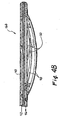
Figure 4b is an enlarged sectional view of the heat exchanger of the catheter (10b) shown inFigure 4a .
-
- The following detailed description is provided for the purpose of describing only certain embodiments or examples of the invention and is not intended to describe all possible embodiments and examples of the invention.
- With reference to
Figures 1-4b , a balloon/heat exchanger catheter elongate catheter body heat exchanger counterpulsation balloon Figure 3B , thecatheter body heat exchanger deflation lumen 52 through which gas or other suitable fluid is alternately infused and withdrawn to effect inflation and deflation of thecounterpulsation balloon outflow lumens heat exchanger fluid inflow lumen 54 is connected to the proximal end of theheat exchanger fluid outflow lumen 56 is connected to the distal end of theheat exchanger heat exchanger - In some embodiments, such as that shown in
Figure 3 , thecounterpulsation balloon 14, may be positioned on a portion of thecatheter body 12 that is distal to theheat exchanger 16. In other embodiments, such as those shown inFigures 4a and4b , thecounterpulsation balloon 14a, 14b may be positioned on a portion of the catheter body that is proximal to theheat exchanger 16a, 16b. Additionally, hybrids or combinations of these designs may also be employed wherein one or more heat exchangers may be positioned proximal and distal to the counterpulsation balloon. - The
catheter body counterpulsation balloon heat exchanger Figures 3, 3a and4 ) orstraight tubes 48 through which the heat exchange medium is circulated. In other embodiments, not shown, the heat exchanger may comprises a thermoelectric element or chemically cooled member mounted within or on the catheter body and connected to the extracorporeal drive/control apparatus 30 by a wire or other communication pathway that extends through thecatheter body 12 to deliver electrical current, chemical activators or other forms of energy to the heat exchanger for the purpose of causing the heat exchanger to warm and/or cool as needed to maintain the desired temperature. - The drive/
control apparatus 30 is useable to drive and control theheat exchanger counterpulsation balloon heat exchanger control apparatus 30 comprises a heater/cooler 34 for causing theheat exchanger control apparatus 30 comprises acontroller 32 such as a microprocessor or computer, a heater/cooler 34 for heating and cooling theheat exchanger temperature signal 38 to thecontroller 32 and an electrocardiogram (ECG) monitoring apparatus for providing an ECG signal to thecontroller 32. - Specific examples of the types of apparatus that comprise the heater/cooler 34 and the portions or function of the
controller 32 that control theheat exchanger temperature signal 40 are described in thePCT International Publication WO OO/10494 controller 32 receive asignal 40 indicative of such monitored esophageal temperature. A desired target temperature is set or inputted into thecontroller 32 and thecontroller 32 is programmed to cause the heater/cooler to heat or cool theheat exchanger - With respect to driving (e.g., inflating and deflating) and controlling of the
counterpulsation balloon control apparatus 30 comprises a pump (IABP) for pumping inflation fluid into and out of the counterpulsation balloon at specific times in relation to the cardiac cycle or ECG. Specific examples of the IABP and the other components/functions of thecontroller 32 used to drive and control thecounterpulsation balloon ECG signal 40 are described in United States Patent Nos.3,504,662 (Goetz et al. ) and3,504,662 (Jones ). - It will be appreciated that, in embodiments such as those shown in
Figures 4-4b , wherein theheat exchanger 16a, 16b is located on the catheter distal to thecounterpulsation balloon 14a, 14b, it may be necessary or desirable for theheat exchanger 16a, 16b to reside within the arch of the aorta AA in order for thecounterpulsation balloon 14a, 14b to be optimally positioned within the thoraco-abdominal aorta A inferior to the left subclavian artery LSA, but still superior to other branches of the aorta such as the superior mesenteric and renal arteries. In such cases, it may be desirable to construct or utilize theheat exchanger 16a, 16b in a way that avoids blocking or disrupting flow into the coronary ostia CO, brachiocephalic trunk BCT, left common carotid artery LCA and/or left subclavian artery LSA. As shown inFigure 4 , this may be accomplished by simply causing the heat exchanger 16a to be smaller in diameter than the lumen of the aortic arch AA such that flow space exists around theheat exchanger 16 and the coronary ostia CO, brachiocephalic trunk BCT, left common carotid artery LCA and/or left subclavian artery LSA remain unobstructed. Another approach, as shown inFigures 4a-4b , is to construct theheat exchanger 16b such that itsheat exchange elements 48, when fully deployed and operational, cannot obstruct or block the coronary ostia CO, brachiocephalic trunk BCT, left common carotid artery LCA and/or left subclavian artery LSA. In the particular embodiment shown inFigures 4a-4b , the distal portion of thecatheter body 12b is preformed to a "J" shape and theheat exchanger 16b comprises a plurality of arcuateheat exchange tubes 48 that are disposed on the underside US of the J shapedcatheter body 12 such that theheat exchange tubes 48 remain adjacent the wall of the aorta A that is opposite the brachiocephalic trunk BCT, left common carotid artery LCA and/or left subclavian artery LSA. - The cooling of the patient's body may cause some shivering to occur, if the patient's core body temperature is cooled to less than about 35.5°C. In such cases, it may be desirable to administer an anti-shivering treatment to prevent or lessen the shivering and enhance the patient's comfort. Such anti-shivering treatment may comprise the mere application of warmth to the patient's skin as may be accomplished by a warming blanket of the type commonly used in hospitals. Alternatively or additionally, such anti-shivering treatment may comprise the administration of drugs or agents to minimize or prevent the shivering response. Examples of agents that are useable for this purpose are described in the United States Patent No.
6,231,594 (Dae et al. ). For example, an anti-shivering treatment may comprise the steps of: - (i) administering an initial bolus dose of a first anti-thermoregulatory response agent to the patient (for example an oral dose of a serotonin 5 HT1 a receptor agonist such as 60 mg of buspirone);
- (ii) administering a subsequent dose of a second anti-thermoregulatory response agent to the patient (for example an initial intravenous dose of any opioid receptor agonist such as 50 mg of meperidine administered by slow push followed by a similar second dose); and
- (iii) administering a further dose of the second anti-thermoregulatory response agent by constant IV administration (for example, constant IV administration of about 25 mg/hr of meperidine).
- (i) administering a first dose of an anti-thermoregulatory response agent to the patient (for example an intravenous dose of an µ opioid receptor agonist such as 50 mg of meperidine administered by slow push and infused over about 5 minutes);
- (ii) administering a second dose of the anti-thermoregulatory response agent to the patient (for example, about 15 minutes after the initial administration of meperidine, an additional 50 mg of meperidine is administered by slow IV push);
- (iii) administering a third dose of the anti-thermoregulatory response agent by constant IV administration (for example, constant IV administration of about 25 mg/hr of meperidine maintained for the duration of the time that the patient's temperature is below the shivering threshold);
- (iv) an intravenous temperature control catheter of the general type described above is introduced into the vasculature of the patient and the heat exchange region of the catheter is placed in the IVC and cooling is begun at the maximum rate. The patient is thereafter maintained at a therapeutically low temperature even below the shivering threshold.
Another class of anti-shivering drugs that may be particularly useful are the alpha-adrenergic receptor agonists, such as dexmedetomidine and clonidine. - Although several illustrative examples of means for practicing the invention are described above, these examples are by no means exhaustive of all possible means for practicing the invention. For example, as described in the Summary of the Invention, instead of using a combination heat exchange/IABP catheter as shown in the drawings, a standard or conventional IABP catheter may be used and a separate heat exchange catheter may be deployed in the aorta or elsewhere, such as in the inferior vena cava or venous vasculature, to effect the desired cooling of the patient's heart, other body parts or entire body. Other modifications to the embodiment shown in the drawings are also possible. The scope of the invention should therefore be determined with reference to the appended claims, along with the full range of equivalents to which those clams are entitled.
Claims (13)
- A heat exchange/intra-aortic counterpulsation catheter device (10, 10a, 10b) comprising an elongate catheter (12, 12a, 12b) having a proximal end and a distal end, said catheter being advancable, distal-end-first, into the aorta of a human or veterinary patient and a heat exchanger (16, 16a, 16b) useable to cool at least a portion of the patients body to a temperature that is at least 1°C below normothermia, said heat exchange/intra-aortic counterpulsation catheter device being further characterized by:a counterpulsation balloon (14, 14a, 14b) useable for effecting intra-aortic balloon counterpulsation; anddriver/control apparatus (30) connectable to the catheter and useable to drive and control the heat exchanger and the counterpulsation balloon.
- A device according to Claim 1 wherein the heat exchanger comprises a heat exchanger through which heat exchange fluid is circulated.
- A device according to Claim 2 wherein said heat exchanger comprises a heat exchange balloon (20, 48).
- A device according to Claim 3 wherein the heat exchanger comprises a single-lobed heat exchange balloon.
- A device according to Claim 3 wherein the heat exchanger comprises a multi-lobed heat exchange balloon.
- A device according to Claim 1 wherein at least a portion of the heat exchanger is metallic.
- A device according to Claim 3 wherein the heat exchange balloon and the counterpulsation balloon comprise a single balloon that is useable for both counterpulsation and heat exchange.
- A device according to Claim 1 wherein the heat exchanger comprises a heat exchange surface and wherein the device further comprises a flow disruption surface associated with the heat exchange surface, the flow disruption surface being configured to disrupt the laminarity of blood flow adjacent to the heat exchange surface, thereby enhancing the efficiency by which the heat exchanger exchanges heat with the flowing blood.
- A device according to Claim 1 wherein the counterpulsation balloon is positioned at a first location on the catheter and the heat exchanger comprises a heat exchange surface located at a second location on the catheter.
- A device according to Claim 9 wherein the fist location is closer to the distal end of the catheter than the second location.
- A device according to Claim 9 wherein the second location is closer to the distal end of the catheter than the first location.
- A device according to Claim 9 wherein the heat exchanger and the counterpulsation balloon comprise a single balloon which is a) configured and useable to effect intra-aortic counterpulsation and b) receives a heat exchange medium such that heat is exchanged between the heat exchange medium and the blood, through at least a portion of the balloon.
- A device according to Claim 1, wherein:Said driver/control apparatus (30) causes a) inflation and deflation of the counterpulsation balloon in response to the patient's cardiac cycle to effect intra-aortic balloon counterpulsation that results in a beneficial effect on the patient and b) at least cooling of the heat exchanger to cause cooling of at least a portion of the patient's body to a temperature that is at least 1°C below normothermia.
Priority Applications (1)
| Application Number | Priority Date | Filing Date | Title |
|---|---|---|---|
| EP08164989A EP2000118B1 (en) | 2001-10-26 | 2002-10-18 | Intra-Aortic Balloon Counterpulsation with Concurrent Hypothermia |
Applications Claiming Priority (3)
| Application Number | Priority Date | Filing Date | Title |
|---|---|---|---|
| US15220 | 1987-02-17 | ||
| US10/015,220 US6800068B1 (en) | 2001-10-26 | 2001-10-26 | Intra-aortic balloon counterpulsation with concurrent hypothermia |
| PCT/US2002/033287 WO2003037158A2 (en) | 2001-10-26 | 2002-10-18 | Intra-aortic balloon counterpulsation with concurrent hypothermia |
Related Child Applications (2)
| Application Number | Title | Priority Date | Filing Date |
|---|---|---|---|
| EP08164989A Division EP2000118B1 (en) | 2001-10-26 | 2002-10-18 | Intra-Aortic Balloon Counterpulsation with Concurrent Hypothermia |
| EP08164989.9 Division-Into | 2008-09-24 |
Publications (3)
| Publication Number | Publication Date |
|---|---|
| EP1443880A2 EP1443880A2 (en) | 2004-08-11 |
| EP1443880A4 EP1443880A4 (en) | 2005-06-15 |
| EP1443880B1 true EP1443880B1 (en) | 2010-03-31 |
Family
ID=21770160
Family Applications (2)
| Application Number | Title | Priority Date | Filing Date |
|---|---|---|---|
| EP02780480A Expired - Lifetime EP1443880B1 (en) | 2001-10-26 | 2002-10-18 | Intra-aortic balloon counterpulsation with concurrent hypothermia |
| EP08164989A Expired - Lifetime EP2000118B1 (en) | 2001-10-26 | 2002-10-18 | Intra-Aortic Balloon Counterpulsation with Concurrent Hypothermia |
Family Applications After (1)
| Application Number | Title | Priority Date | Filing Date |
|---|---|---|---|
| EP08164989A Expired - Lifetime EP2000118B1 (en) | 2001-10-26 | 2002-10-18 | Intra-Aortic Balloon Counterpulsation with Concurrent Hypothermia |
Country Status (9)
| Country | Link |
|---|---|
| US (6) | US6800068B1 (en) |
| EP (2) | EP1443880B1 (en) |
| JP (1) | JP4429720B2 (en) |
| AT (2) | ATE462388T1 (en) |
| AU (1) | AU2009201658B2 (en) |
| CA (1) | CA2463864C (en) |
| DE (1) | DE60235826D1 (en) |
| IL (1) | IL161502A0 (en) |
| WO (1) | WO2003037158A2 (en) |
Cited By (1)
| Publication number | Priority date | Publication date | Assignee | Title |
|---|---|---|---|---|
| US10888644B2 (en) | 2019-02-06 | 2021-01-12 | inQB8 Medical Technologies, LLC | Intra-cardiac left atrial and dual support systems |
Families Citing this family (31)
| Publication number | Priority date | Publication date | Assignee | Title |
|---|---|---|---|---|
| US6800068B1 (en) * | 2001-10-26 | 2004-10-05 | Radiant Medical, Inc. | Intra-aortic balloon counterpulsation with concurrent hypothermia |
| US8540618B2 (en) | 2003-01-31 | 2013-09-24 | L-Vad Technology, Inc. | Stable aortic blood pump implant |
| US8721515B2 (en) * | 2003-01-31 | 2014-05-13 | L-Vad Technology, Inc. | Rigid body aortic blood pump implant |
| US7450988B2 (en) * | 2004-06-04 | 2008-11-11 | Cardiac Pacemakers, Inc. | Method and apparatus for minimizing post-infarct ventricular remodeling |
| US20060253193A1 (en) * | 2005-05-03 | 2006-11-09 | Lichtenstein Samuel V | Mechanical means for controlling blood pressure |
| US20070032547A1 (en) * | 2005-08-04 | 2007-02-08 | Mark Friedman | Method and device for treating migraine, tension-type and post-traumatic headache, atypical facial pain, and cervical muscle hyperactivity |
| US20070225781A1 (en) * | 2006-03-21 | 2007-09-27 | Nidus Medical, Llc | Apparatus and methods for altering temperature in a region within the body |
| US20070276444A1 (en) * | 2006-05-24 | 2007-11-29 | Daniel Gelbart | Self-powered leadless pacemaker |
| US20070287879A1 (en) * | 2006-06-13 | 2007-12-13 | Daniel Gelbart | Mechanical means for controlling blood pressure |
| EP2084277A2 (en) * | 2006-10-06 | 2009-08-05 | Polytechnic University | Ph sensitive liposome composition |
| US7892270B2 (en) * | 2006-11-21 | 2011-02-22 | Zoll Circulation Inc. | Temperature management system and method for burn patients |
| CA2684807A1 (en) | 2007-04-05 | 2008-10-16 | Velomedix, Inc. | Automated therapy system and method |
| WO2009009540A1 (en) | 2007-07-09 | 2009-01-15 | Velomedix, Inc. | Hypothermia devices and methods |
| GB2476751B (en) * | 2008-10-08 | 2013-08-07 | Bedrock Inv S Llc | Measuring shivering during therapeutic temperature control |
| US8608696B1 (en) | 2009-02-24 | 2013-12-17 | North Carolina State University | Rapid fluid cooling devices and methods for cooling fluids |
| US20110092967A1 (en) * | 2009-10-21 | 2011-04-21 | Medtronic Cryocath Lp | Deflation mechanism for a medical device |
| AU2011242697B2 (en) | 2010-04-21 | 2015-01-22 | Government Of The United States | Fluoroscopy-independent, endovascular aortic occlusion system |
| WO2012006625A2 (en) | 2010-07-09 | 2012-01-12 | Velomedix, Inc. | Method and apparatus for pressure measurement |
| DE102012104381A1 (en) * | 2012-05-22 | 2013-11-28 | Acandis Gmbh & Co. Kg | Medical system for the endovascular tempering of blood and medical catheters |
| US9474882B2 (en) | 2013-02-26 | 2016-10-25 | Prytime Medical Devices, Inc. | Fluoroscopy-independent balloon guided occlusion catheter and methods |
| EP3424552B1 (en) | 2013-09-09 | 2020-04-15 | Prytime Medical Devices, Inc. | Low-profile occlusion catheter |
| AT514812B1 (en) * | 2013-12-19 | 2015-04-15 | Univ Wien Med | Aortic catheter and resuscitation set with such an aortic catheter |
| CA2941438C (en) | 2014-06-10 | 2018-04-10 | Prytime Medical Devices, Inc. | Conduit guiding tip |
| EP3270997B1 (en) | 2015-03-19 | 2019-07-03 | Prytime Medical Devices, Inc. | System for low-profile occlusion balloon catheter |
| AU2017272335B2 (en) | 2016-06-02 | 2018-06-14 | Prytime Medical Devices, Inc. | System and method for low profile occlusion balloon catheter |
| WO2018123958A1 (en) * | 2016-12-27 | 2018-07-05 | 日本ゼオン株式会社 | Balloon catheter for iabp |
| CN110446523B (en) | 2017-01-12 | 2022-06-10 | 加利福尼亚大学董事会 | Intravascular perfusion enhancement for critical care |
| EP3612086A4 (en) | 2017-04-21 | 2021-01-20 | The Regents of the University of California, A California Corporation | Aortic flow meter and pump for partial-aortic occlusion |
| KR20220007043A (en) * | 2019-03-29 | 2022-01-18 | 아비오메드, 인크. | Systems and Methods for Left Ventricular Unloading in Biological Therapy or Vector Gene Therapy |
| KR20210154204A (en) | 2019-04-19 | 2021-12-20 | 아비오메드, 인크. | Cooled Mechanical Circulation Support System and How It Works |
| AU2021239935A1 (en) | 2020-03-16 | 2022-10-06 | Certus Critical Care, Inc. | Blood flow control devices, systems, and methods and error detection thereof |
Family Cites Families (55)
| Publication number | Priority date | Publication date | Assignee | Title |
|---|---|---|---|---|
| US3425419A (en) | 1964-08-08 | 1969-02-04 | Angelo Actis Dato | Method of lowering and raising the temperature of the human body |
| US3425484A (en) | 1966-02-02 | 1969-02-04 | United States Steel Corp | Apparatus for introducing coating metal to a vapor-deposition chamber |
| US3425429A (en) | 1967-01-11 | 1969-02-04 | Chevron Res | Method of moving viscous crude oil through a pipeline |
| US3504662A (en) | 1967-05-16 | 1970-04-07 | Avco Corp | Intra-arterial blood pump |
| US4111209A (en) | 1977-04-18 | 1978-09-05 | Datascope Corporation | Topical hypothermia apparatus and method for treating the human body and the like |
| US4762130A (en) | 1987-01-15 | 1988-08-09 | Thomas J. Fogarty | Catheter with corkscrew-like balloon |
| JPS6446056U (en) | 1987-09-17 | 1989-03-22 | ||
| US5151100A (en) | 1988-10-28 | 1992-09-29 | Boston Scientific Corporation | Heating catheters |
| US5624392A (en) | 1990-05-11 | 1997-04-29 | Saab; Mark A. | Heat transfer catheters and methods of making and using same |
| US5211631A (en) | 1991-07-24 | 1993-05-18 | Sheaff Charles M | Patient warming apparatus |
| US5417653A (en) | 1993-01-21 | 1995-05-23 | Sahota; Harvinder | Method for minimizing restenosis |
| US6110168A (en) | 1993-02-10 | 2000-08-29 | Radiant Medical, Inc. | Method and apparatus for controlling a patient's body temperature by in situ blood temperature modifications |
| US5486208A (en) | 1993-02-10 | 1996-01-23 | Ginsburg; Robert | Method and apparatus for controlling a patient's body temperature by in situ blood temperature modification |
| US5837003A (en) | 1993-02-10 | 1998-11-17 | Radiant Medical, Inc. | Method and apparatus for controlling a patient's body temperature by in situ blood temperature modification |
| US6620188B1 (en) | 1998-08-24 | 2003-09-16 | Radiant Medical, Inc. | Methods and apparatus for regional and whole body temperature modification |
| US6033383A (en) | 1996-12-19 | 2000-03-07 | Ginsburg; Robert | Temperature regulating catheter and methods |
| US5626618A (en) * | 1993-09-24 | 1997-05-06 | The Ohio State University | Mechanical adjunct to cardiopulmonary resuscitation (CPR), and an electrical adjunct to defibrillation countershock, cardiac pacing, and cardiac monitoring |
| US5718861A (en) | 1993-12-20 | 1998-02-17 | C. R. Bard, Incorporated | Method of forming intra-aortic balloon catheters |
| DE69519068T2 (en) * | 1994-03-24 | 2001-03-22 | Idemitsu Petrochemical Co | METHOD AND DEVICE FOR PRODUCING AIR PILLOWS |
| US5716386A (en) | 1994-06-27 | 1998-02-10 | The Ohio State University | Non-invasive aortic impingement and core and cerebral temperature manipulation |
| US5914345A (en) | 1994-10-11 | 1999-06-22 | Endoluminal Therapeutics, Inc. | Treatment of tissues to reduce subsequent response to injury |
| DE69631430T2 (en) | 1995-11-13 | 2004-12-02 | Boston Scientific Corp., Natick | Intra-aortic balloon catheter |
| EP0966640B1 (en) * | 1997-02-20 | 2002-06-05 | Unilever Plc | Housing for freezer cabinets, and housing system |
| US6544797B1 (en) * | 1997-04-09 | 2003-04-08 | Biosite Diagnostics, Inc. | Compositions and methods for inhibiting light-induced inactivation of biological reagents |
| US5971979A (en) * | 1997-12-02 | 1999-10-26 | Odyssey Technologies, Inc. | Method for cryogenic inhibition of hyperplasia |
| US6251129B1 (en) | 1998-03-24 | 2001-06-26 | Innercool Therapies, Inc. | Method for low temperature thrombolysis and low temperature thrombolytic agent with selective organ temperature control |
| US6051019A (en) | 1998-01-23 | 2000-04-18 | Del Mar Medical Technologies, Inc. | Selective organ hypothermia method and apparatus |
| US6238428B1 (en) | 1998-01-23 | 2001-05-29 | Innercool Therapies, Inc. | Selective organ cooling apparatus and method employing turbulence-inducing element with curved terminations |
| US6843800B1 (en) | 1998-01-23 | 2005-01-18 | Innercool Therapies, Inc. | Patient temperature regulation method and apparatus |
| US6096068A (en) | 1998-01-23 | 2000-08-01 | Innercool Therapies, Inc. | Selective organ cooling catheter and method of using the same |
| US6245095B1 (en) | 1998-03-24 | 2001-06-12 | Innercool Therapies, Inc. | Method and apparatus for location and temperature specific drug action such as thrombolysis |
| US6261312B1 (en) | 1998-06-23 | 2001-07-17 | Innercool Therapies, Inc. | Inflatable catheter for selective organ heating and cooling and method of using the same |
| US6312452B1 (en) | 1998-01-23 | 2001-11-06 | Innercool Therapies, Inc. | Selective organ cooling catheter with guidewire apparatus and temperature-monitoring device |
| US6042559A (en) | 1998-02-24 | 2000-03-28 | Innercool Therapies, Inc. | Insulated catheter for selective organ perfusion |
| US6224624B1 (en) | 1998-03-24 | 2001-05-01 | Innercool Therapies, Inc. | Selective organ cooling apparatus and method |
| US6368304B1 (en) | 1999-02-19 | 2002-04-09 | Alsius Corporation | Central venous catheter with heat exchange membrane |
| US6126684A (en) | 1998-04-21 | 2000-10-03 | The Regents Of The University Of California | Indwelling heat exchange catheter and method of using same |
| US6338727B1 (en) | 1998-08-13 | 2002-01-15 | Alsius Corporation | Indwelling heat exchange catheter and method of using same |
| US6149670A (en) | 1999-03-11 | 2000-11-21 | Alsius Corporation | Method and system for treating cardiac arrest using hypothermia |
| US6610083B2 (en) | 1998-08-24 | 2003-08-26 | Radiant Medical, Inc. | Multiple lumen heat exchange catheters |
| US6146411A (en) | 1998-12-24 | 2000-11-14 | Alsius Corporation | Cooling system for indwelling heat exchange catheter |
| US6299599B1 (en) | 1999-02-19 | 2001-10-09 | Alsius Corporation | Dual balloon central venous line catheter temperature control system |
| US6554797B1 (en) * | 1999-02-19 | 2003-04-29 | Alsius Corporation | Method and system for patient temperature management and central venous access |
| EP1029520B1 (en) | 1999-02-19 | 2002-08-14 | Alsius Corporation | Central venous line catheter having temperature control system |
| US6405080B1 (en) | 1999-03-11 | 2002-06-11 | Alsius Corporation | Method and system for treating cardiac arrest |
| US6019783A (en) * | 1999-03-02 | 2000-02-01 | Alsius Corporation | Cooling system for therapeutic catheter |
| US6290717B1 (en) | 1999-03-31 | 2001-09-18 | Alsius Corporation | Temperature probe and interconnect cable for hypothermia catheter temperature feedback |
| US6190304B1 (en) * | 1999-07-13 | 2001-02-20 | University Of North Texas Health Science Center At Fort Worth | Enhanced intra-aortic balloon assist device |
| US6287326B1 (en) | 1999-08-02 | 2001-09-11 | Alsius Corporation | Catheter with coiled multi-lumen heat transfer extension |
| US6231594B1 (en) | 1999-08-11 | 2001-05-15 | Radiant Medical, Inc. | Method of controlling body temperature while reducing shivering |
| US6264679B1 (en) | 1999-08-20 | 2001-07-24 | Radiant Medical, Inc. | Heat exchange catheter with discrete heat exchange elements |
| US6283959B1 (en) * | 1999-08-23 | 2001-09-04 | Cyrocath Technologies, Inc. | Endovascular cryotreatment catheter |
| US6645233B1 (en) * | 2001-09-27 | 2003-11-11 | Gregory M. Ayers | Drainage tube with heat transfer function and methods of use |
| US6800068B1 (en) * | 2001-10-26 | 2004-10-05 | Radiant Medical, Inc. | Intra-aortic balloon counterpulsation with concurrent hypothermia |
| US7144407B1 (en) * | 2002-05-30 | 2006-12-05 | Alsius Corporation | Cardiovascular intra aortic balloon pump catheter with heat exchange function and methods of use |
-
2001
- 2001-10-26 US US10/015,220 patent/US6800068B1/en not_active Expired - Lifetime
-
2002
- 2002-10-18 EP EP02780480A patent/EP1443880B1/en not_active Expired - Lifetime
- 2002-10-18 CA CA2463864A patent/CA2463864C/en not_active Expired - Fee Related
- 2002-10-18 AT AT02780480T patent/ATE462388T1/en active
- 2002-10-18 JP JP2003539508A patent/JP4429720B2/en not_active Expired - Fee Related
- 2002-10-18 IL IL16150202A patent/IL161502A0/en unknown
- 2002-10-18 WO PCT/US2002/033287 patent/WO2003037158A2/en active Application Filing
- 2002-10-18 DE DE60235826T patent/DE60235826D1/en not_active Expired - Lifetime
- 2002-10-18 EP EP08164989A patent/EP2000118B1/en not_active Expired - Lifetime
- 2002-10-18 AT AT08164989T patent/ATE538764T1/en active
-
2004
- 2004-09-02 US US10/933,970 patent/US7959643B2/en not_active Expired - Fee Related
-
2009
- 2009-04-27 AU AU2009201658A patent/AU2009201658B2/en not_active Ceased
-
2011
- 2011-06-14 US US13/160,285 patent/US8430899B2/en not_active Expired - Fee Related
-
2013
- 2013-04-29 US US13/872,984 patent/US9180236B2/en not_active Expired - Fee Related
-
2015
- 2015-11-09 US US14/936,507 patent/US9533086B2/en not_active Expired - Fee Related
-
2017
- 2017-01-03 US US15/397,602 patent/US20170266359A1/en not_active Abandoned
Cited By (2)
| Publication number | Priority date | Publication date | Assignee | Title |
|---|---|---|---|---|
| US10888644B2 (en) | 2019-02-06 | 2021-01-12 | inQB8 Medical Technologies, LLC | Intra-cardiac left atrial and dual support systems |
| US11883640B2 (en) | 2019-02-06 | 2024-01-30 | inQB8 Medical Technologies, LLC | Intra-cardiac left atrial and dual support systems |
Also Published As
| Publication number | Publication date |
|---|---|
| US20160058931A1 (en) | 2016-03-03 |
| EP1443880A2 (en) | 2004-08-11 |
| US20050043579A1 (en) | 2005-02-24 |
| AU2009201658B2 (en) | 2011-05-26 |
| US20170266359A1 (en) | 2017-09-21 |
| ATE462388T1 (en) | 2010-04-15 |
| US9180236B2 (en) | 2015-11-10 |
| US7959643B2 (en) | 2011-06-14 |
| US8430899B2 (en) | 2013-04-30 |
| ATE538764T1 (en) | 2012-01-15 |
| IL161502A0 (en) | 2004-09-27 |
| AU2009201658A1 (en) | 2009-05-21 |
| CA2463864A1 (en) | 2003-05-08 |
| CA2463864C (en) | 2010-12-21 |
| US20120095282A1 (en) | 2012-04-19 |
| WO2003037158A3 (en) | 2004-02-19 |
| DE60235826D1 (en) | 2010-05-12 |
| JP2005507695A (en) | 2005-03-24 |
| EP2000118A2 (en) | 2008-12-10 |
| EP1443880A4 (en) | 2005-06-15 |
| WO2003037158A2 (en) | 2003-05-08 |
| EP2000118B1 (en) | 2011-12-28 |
| US6800068B1 (en) | 2004-10-05 |
| EP2000118A3 (en) | 2010-11-03 |
| US20130310632A1 (en) | 2013-11-21 |
| JP4429720B2 (en) | 2010-03-10 |
| US9533086B2 (en) | 2017-01-03 |
Similar Documents
| Publication | Publication Date | Title |
|---|---|---|
| US9533086B2 (en) | Intra-aortic balloon counterpulsation with concurrent hypothermia | |
| US7172586B1 (en) | Method of inotropic treatment of circulatory failure using hypothermia | |
| US6786218B2 (en) | Medical procedure | |
| US9138344B2 (en) | Apparatus and method of gastric cooling using balloon catheter | |
| US6589271B1 (en) | Indwelling heat exchange catheter | |
| US7951183B2 (en) | Medical procedure | |
| US20120203201A1 (en) | Methods for Preparing a Heat Exchange Catheter System and for Heating and/or Cooling a Subject's Body | |
| US10420675B2 (en) | Apparatus and method for esophageal cooling | |
| WO2006023056A2 (en) | System and method for treating cardiac arrest and myocardial infarction | |
| US7425216B2 (en) | System and method for treating cardiac arrest and myocardial infarction | |
| US6893454B2 (en) | Intrarectal heat exchange catheter | |
| EP1267760A2 (en) | Medical procedure | |
| AU2002343534A1 (en) | Intra-aortic balloon counterpulsation with concurrent hypothermia | |
| AU2007242941B2 (en) | Methods and apparatus for regional and whole body temperature modification |
Legal Events
| Date | Code | Title | Description |
|---|---|---|---|
| PUAI | Public reference made under article 153(3) epc to a published international application that has entered the european phase |
Free format text: ORIGINAL CODE: 0009012 |
|
| 17P | Request for examination filed |
Effective date: 20040504 |
|
| AK | Designated contracting states |
Kind code of ref document: A2 Designated state(s): AT BE BG CH CY CZ DE DK EE ES FI FR GB GR IE IT LI LU MC NL PT SE SK TR |
|
| AX | Request for extension of the european patent |
Extension state: AL LT LV MK RO SI |
|
| A4 | Supplementary search report drawn up and despatched |
Effective date: 20050504 |
|
| RIC1 | Information provided on ipc code assigned before grant |
Ipc: 7A 61F 7/12 A Ipc: 7A 61M 1/10 B |
|
| 17Q | First examination report despatched |
Effective date: 20061116 |
|
| GRAP | Despatch of communication of intention to grant a patent |
Free format text: ORIGINAL CODE: EPIDOSNIGR1 |
|
| GRAS | Grant fee paid |
Free format text: ORIGINAL CODE: EPIDOSNIGR3 |
|
| GRAA | (expected) grant |
Free format text: ORIGINAL CODE: 0009210 |
|
| AK | Designated contracting states |
Kind code of ref document: B1 Designated state(s): AT BE BG CH CY CZ DE DK EE ES FI FR GB GR IE IT LI LU MC NL PT SE SK TR |
|
| REG | Reference to a national code |
Ref country code: GB Ref legal event code: FG4D Ref country code: CH Ref legal event code: EP |
|
| REG | Reference to a national code |
Ref country code: IE Ref legal event code: FG4D |
|
| REF | Corresponds to: |
Ref document number: 60235826 Country of ref document: DE Date of ref document: 20100512 Kind code of ref document: P |
|
| REG | Reference to a national code |
Ref country code: NL Ref legal event code: VDEP Effective date: 20100331 |
|
| PG25 | Lapsed in a contracting state [announced via postgrant information from national office to epo] |
Ref country code: FI Free format text: LAPSE BECAUSE OF FAILURE TO SUBMIT A TRANSLATION OF THE DESCRIPTION OR TO PAY THE FEE WITHIN THE PRESCRIBED TIME-LIMIT Effective date: 20100331 |
|
| PG25 | Lapsed in a contracting state [announced via postgrant information from national office to epo] |
Ref country code: CY Free format text: LAPSE BECAUSE OF FAILURE TO SUBMIT A TRANSLATION OF THE DESCRIPTION OR TO PAY THE FEE WITHIN THE PRESCRIBED TIME-LIMIT Effective date: 20100331 Ref country code: SE Free format text: LAPSE BECAUSE OF FAILURE TO SUBMIT A TRANSLATION OF THE DESCRIPTION OR TO PAY THE FEE WITHIN THE PRESCRIBED TIME-LIMIT Effective date: 20100331 Ref country code: NL Free format text: LAPSE BECAUSE OF FAILURE TO SUBMIT A TRANSLATION OF THE DESCRIPTION OR TO PAY THE FEE WITHIN THE PRESCRIBED TIME-LIMIT Effective date: 20100331 Ref country code: ES Free format text: LAPSE BECAUSE OF FAILURE TO SUBMIT A TRANSLATION OF THE DESCRIPTION OR TO PAY THE FEE WITHIN THE PRESCRIBED TIME-LIMIT Effective date: 20100712 Ref country code: EE Free format text: LAPSE BECAUSE OF FAILURE TO SUBMIT A TRANSLATION OF THE DESCRIPTION OR TO PAY THE FEE WITHIN THE PRESCRIBED TIME-LIMIT Effective date: 20100331 Ref country code: BE Free format text: LAPSE BECAUSE OF FAILURE TO SUBMIT A TRANSLATION OF THE DESCRIPTION OR TO PAY THE FEE WITHIN THE PRESCRIBED TIME-LIMIT Effective date: 20100331 |
|
| PG25 | Lapsed in a contracting state [announced via postgrant information from national office to epo] |
Ref country code: SK Free format text: LAPSE BECAUSE OF FAILURE TO SUBMIT A TRANSLATION OF THE DESCRIPTION OR TO PAY THE FEE WITHIN THE PRESCRIBED TIME-LIMIT Effective date: 20100331 Ref country code: CZ Free format text: LAPSE BECAUSE OF FAILURE TO SUBMIT A TRANSLATION OF THE DESCRIPTION OR TO PAY THE FEE WITHIN THE PRESCRIBED TIME-LIMIT Effective date: 20100331 |
|
| PG25 | Lapsed in a contracting state [announced via postgrant information from national office to epo] |
Ref country code: DK Free format text: LAPSE BECAUSE OF FAILURE TO SUBMIT A TRANSLATION OF THE DESCRIPTION OR TO PAY THE FEE WITHIN THE PRESCRIBED TIME-LIMIT Effective date: 20100331 Ref country code: PT Free format text: LAPSE BECAUSE OF FAILURE TO SUBMIT A TRANSLATION OF THE DESCRIPTION OR TO PAY THE FEE WITHIN THE PRESCRIBED TIME-LIMIT Effective date: 20100802 |
|
| PLBE | No opposition filed within time limit |
Free format text: ORIGINAL CODE: 0009261 |
|
| STAA | Information on the status of an ep patent application or granted ep patent |
Free format text: STATUS: NO OPPOSITION FILED WITHIN TIME LIMIT |
|
| 26N | No opposition filed |
Effective date: 20110104 |
|
| PG25 | Lapsed in a contracting state [announced via postgrant information from national office to epo] |
Ref country code: IT Free format text: LAPSE BECAUSE OF FAILURE TO SUBMIT A TRANSLATION OF THE DESCRIPTION OR TO PAY THE FEE WITHIN THE PRESCRIBED TIME-LIMIT Effective date: 20100331 |
|
| PG25 | Lapsed in a contracting state [announced via postgrant information from national office to epo] |
Ref country code: MC Free format text: LAPSE BECAUSE OF NON-PAYMENT OF DUE FEES Effective date: 20101031 |
|
| PG25 | Lapsed in a contracting state [announced via postgrant information from national office to epo] |
Ref country code: LU Free format text: LAPSE BECAUSE OF NON-PAYMENT OF DUE FEES Effective date: 20101018 Ref country code: BG Free format text: LAPSE BECAUSE OF FAILURE TO SUBMIT A TRANSLATION OF THE DESCRIPTION OR TO PAY THE FEE WITHIN THE PRESCRIBED TIME-LIMIT Effective date: 20100331 |
|
| PG25 | Lapsed in a contracting state [announced via postgrant information from national office to epo] |
Ref country code: TR Free format text: LAPSE BECAUSE OF FAILURE TO SUBMIT A TRANSLATION OF THE DESCRIPTION OR TO PAY THE FEE WITHIN THE PRESCRIBED TIME-LIMIT Effective date: 20100331 |
|
| PG25 | Lapsed in a contracting state [announced via postgrant information from national office to epo] |
Ref country code: BG Free format text: LAPSE BECAUSE OF FAILURE TO SUBMIT A TRANSLATION OF THE DESCRIPTION OR TO PAY THE FEE WITHIN THE PRESCRIBED TIME-LIMIT Effective date: 20100630 |
|
| PG25 | Lapsed in a contracting state [announced via postgrant information from national office to epo] |
Ref country code: GR Free format text: LAPSE BECAUSE OF FAILURE TO SUBMIT A TRANSLATION OF THE DESCRIPTION OR TO PAY THE FEE WITHIN THE PRESCRIBED TIME-LIMIT Effective date: 20100331 |
|
| PGFP | Annual fee paid to national office [announced via postgrant information from national office to epo] |
Ref country code: CH Payment date: 20141027 Year of fee payment: 13 Ref country code: GB Payment date: 20141027 Year of fee payment: 13 Ref country code: IE Payment date: 20141027 Year of fee payment: 13 |
|
| REG | Reference to a national code |
Ref country code: FR Ref legal event code: PLFP Year of fee payment: 14 |
|
| PGFP | Annual fee paid to national office [announced via postgrant information from national office to epo] |
Ref country code: FR Payment date: 20151019 Year of fee payment: 14 |
|
| REG | Reference to a national code |
Ref country code: CH Ref legal event code: PL |
|
| GBPC | Gb: european patent ceased through non-payment of renewal fee |
Effective date: 20151018 |
|
| REG | Reference to a national code |
Ref country code: IE Ref legal event code: MM4A |
|
| PG25 | Lapsed in a contracting state [announced via postgrant information from national office to epo] |
Ref country code: LI Free format text: LAPSE BECAUSE OF NON-PAYMENT OF DUE FEES Effective date: 20151031 Ref country code: GB Free format text: LAPSE BECAUSE OF NON-PAYMENT OF DUE FEES Effective date: 20151018 Ref country code: CH Free format text: LAPSE BECAUSE OF NON-PAYMENT OF DUE FEES Effective date: 20151031 |
|
| PG25 | Lapsed in a contracting state [announced via postgrant information from national office to epo] |
Ref country code: IE Free format text: LAPSE BECAUSE OF NON-PAYMENT OF DUE FEES Effective date: 20151018 |
|
| REG | Reference to a national code |
Ref country code: FR Ref legal event code: ST Effective date: 20170630 |
|
| PG25 | Lapsed in a contracting state [announced via postgrant information from national office to epo] |
Ref country code: FR Free format text: LAPSE BECAUSE OF NON-PAYMENT OF DUE FEES Effective date: 20161102 |
|
| PGFP | Annual fee paid to national office [announced via postgrant information from national office to epo] |
Ref country code: DE Payment date: 20181029 Year of fee payment: 17 Ref country code: AT Payment date: 20181003 Year of fee payment: 17 |
|
| REG | Reference to a national code |
Ref country code: DE Ref legal event code: R119 Ref document number: 60235826 Country of ref document: DE |
|
| PG25 | Lapsed in a contracting state [announced via postgrant information from national office to epo] |
Ref country code: DE Free format text: LAPSE BECAUSE OF NON-PAYMENT OF DUE FEES Effective date: 20200501 |
|
| REG | Reference to a national code |
Ref country code: AT Ref legal event code: MM01 Ref document number: 462388 Country of ref document: AT Kind code of ref document: T Effective date: 20191018 |
|
| PG25 | Lapsed in a contracting state [announced via postgrant information from national office to epo] |
Ref country code: AT Free format text: LAPSE BECAUSE OF NON-PAYMENT OF DUE FEES Effective date: 20191018 |
|
| P01 | Opt-out of the competence of the unified patent court (upc) registered |
Effective date: 20230526 |