EP1449500A2 - Modular bone implant, tool and method - Google Patents
Modular bone implant, tool and method Download PDFInfo
- Publication number
- EP1449500A2 EP1449500A2 EP04250511A EP04250511A EP1449500A2 EP 1449500 A2 EP1449500 A2 EP 1449500A2 EP 04250511 A EP04250511 A EP 04250511A EP 04250511 A EP04250511 A EP 04250511A EP 1449500 A2 EP1449500 A2 EP 1449500A2
- Authority
- EP
- European Patent Office
- Prior art keywords
- tray
- tool
- bore
- keel
- boss
- Prior art date
- Legal status (The legal status is an assumption and is not a legal conclusion. Google has not performed a legal analysis and makes no representation as to the accuracy of the status listed.)
- Granted
Links
Images


Classifications
-
- A—HUMAN NECESSITIES
- A61—MEDICAL OR VETERINARY SCIENCE; HYGIENE
- A61F—FILTERS IMPLANTABLE INTO BLOOD VESSELS; PROSTHESES; DEVICES PROVIDING PATENCY TO, OR PREVENTING COLLAPSING OF, TUBULAR STRUCTURES OF THE BODY, e.g. STENTS; ORTHOPAEDIC, NURSING OR CONTRACEPTIVE DEVICES; FOMENTATION; TREATMENT OR PROTECTION OF EYES OR EARS; BANDAGES, DRESSINGS OR ABSORBENT PADS; FIRST-AID KITS
- A61F2/00—Filters implantable into blood vessels; Prostheses, i.e. artificial substitutes or replacements for parts of the body; Appliances for connecting them with the body; Devices providing patency to, or preventing collapsing of, tubular structures of the body, e.g. stents
- A61F2/02—Prostheses implantable into the body
- A61F2/30—Joints
- A61F2/46—Special tools or methods for implanting or extracting artificial joints, accessories, bone grafts or substitutes, or particular adaptations therefor
- A61F2/4603—Special tools or methods for implanting or extracting artificial joints, accessories, bone grafts or substitutes, or particular adaptations therefor for insertion or extraction of endoprosthetic joints or of accessories thereof
- A61F2/461—Special tools or methods for implanting or extracting artificial joints, accessories, bone grafts or substitutes, or particular adaptations therefor for insertion or extraction of endoprosthetic joints or of accessories thereof of knees
-
- A—HUMAN NECESSITIES
- A61—MEDICAL OR VETERINARY SCIENCE; HYGIENE
- A61F—FILTERS IMPLANTABLE INTO BLOOD VESSELS; PROSTHESES; DEVICES PROVIDING PATENCY TO, OR PREVENTING COLLAPSING OF, TUBULAR STRUCTURES OF THE BODY, e.g. STENTS; ORTHOPAEDIC, NURSING OR CONTRACEPTIVE DEVICES; FOMENTATION; TREATMENT OR PROTECTION OF EYES OR EARS; BANDAGES, DRESSINGS OR ABSORBENT PADS; FIRST-AID KITS
- A61F2/00—Filters implantable into blood vessels; Prostheses, i.e. artificial substitutes or replacements for parts of the body; Appliances for connecting them with the body; Devices providing patency to, or preventing collapsing of, tubular structures of the body, e.g. stents
- A61F2/02—Prostheses implantable into the body
- A61F2/30—Joints
- A61F2/38—Joints for elbows or knees
- A61F2/389—Tibial components
-
- A—HUMAN NECESSITIES
- A61—MEDICAL OR VETERINARY SCIENCE; HYGIENE
- A61F—FILTERS IMPLANTABLE INTO BLOOD VESSELS; PROSTHESES; DEVICES PROVIDING PATENCY TO, OR PREVENTING COLLAPSING OF, TUBULAR STRUCTURES OF THE BODY, e.g. STENTS; ORTHOPAEDIC, NURSING OR CONTRACEPTIVE DEVICES; FOMENTATION; TREATMENT OR PROTECTION OF EYES OR EARS; BANDAGES, DRESSINGS OR ABSORBENT PADS; FIRST-AID KITS
- A61F2/00—Filters implantable into blood vessels; Prostheses, i.e. artificial substitutes or replacements for parts of the body; Appliances for connecting them with the body; Devices providing patency to, or preventing collapsing of, tubular structures of the body, e.g. stents
- A61F2/02—Prostheses implantable into the body
- A61F2/30—Joints
- A61F2/46—Special tools or methods for implanting or extracting artificial joints, accessories, bone grafts or substitutes, or particular adaptations therefor
- A61F2/4637—Special tools or methods for implanting or extracting artificial joints, accessories, bone grafts or substitutes, or particular adaptations therefor for connecting or disconnecting two parts of a prosthesis
-
- A—HUMAN NECESSITIES
- A61—MEDICAL OR VETERINARY SCIENCE; HYGIENE
- A61F—FILTERS IMPLANTABLE INTO BLOOD VESSELS; PROSTHESES; DEVICES PROVIDING PATENCY TO, OR PREVENTING COLLAPSING OF, TUBULAR STRUCTURES OF THE BODY, e.g. STENTS; ORTHOPAEDIC, NURSING OR CONTRACEPTIVE DEVICES; FOMENTATION; TREATMENT OR PROTECTION OF EYES OR EARS; BANDAGES, DRESSINGS OR ABSORBENT PADS; FIRST-AID KITS
- A61F2/00—Filters implantable into blood vessels; Prostheses, i.e. artificial substitutes or replacements for parts of the body; Appliances for connecting them with the body; Devices providing patency to, or preventing collapsing of, tubular structures of the body, e.g. stents
- A61F2/02—Prostheses implantable into the body
- A61F2/30—Joints
- A61F2/46—Special tools or methods for implanting or extracting artificial joints, accessories, bone grafts or substitutes, or particular adaptations therefor
- A61F2/4603—Special tools or methods for implanting or extracting artificial joints, accessories, bone grafts or substitutes, or particular adaptations therefor for insertion or extraction of endoprosthetic joints or of accessories thereof
-
- A—HUMAN NECESSITIES
- A61—MEDICAL OR VETERINARY SCIENCE; HYGIENE
- A61F—FILTERS IMPLANTABLE INTO BLOOD VESSELS; PROSTHESES; DEVICES PROVIDING PATENCY TO, OR PREVENTING COLLAPSING OF, TUBULAR STRUCTURES OF THE BODY, e.g. STENTS; ORTHOPAEDIC, NURSING OR CONTRACEPTIVE DEVICES; FOMENTATION; TREATMENT OR PROTECTION OF EYES OR EARS; BANDAGES, DRESSINGS OR ABSORBENT PADS; FIRST-AID KITS
- A61F2/00—Filters implantable into blood vessels; Prostheses, i.e. artificial substitutes or replacements for parts of the body; Appliances for connecting them with the body; Devices providing patency to, or preventing collapsing of, tubular structures of the body, e.g. stents
- A61F2/02—Prostheses implantable into the body
- A61F2/30—Joints
- A61F2002/30001—Additional features of subject-matter classified in A61F2/28, A61F2/30 and subgroups thereof
- A61F2002/30108—Shapes
- A61F2002/3011—Cross-sections or two-dimensional shapes
- A61F2002/30112—Rounded shapes, e.g. with rounded corners
- A61F2002/30133—Rounded shapes, e.g. with rounded corners kidney-shaped or bean-shaped
-
- A—HUMAN NECESSITIES
- A61—MEDICAL OR VETERINARY SCIENCE; HYGIENE
- A61F—FILTERS IMPLANTABLE INTO BLOOD VESSELS; PROSTHESES; DEVICES PROVIDING PATENCY TO, OR PREVENTING COLLAPSING OF, TUBULAR STRUCTURES OF THE BODY, e.g. STENTS; ORTHOPAEDIC, NURSING OR CONTRACEPTIVE DEVICES; FOMENTATION; TREATMENT OR PROTECTION OF EYES OR EARS; BANDAGES, DRESSINGS OR ABSORBENT PADS; FIRST-AID KITS
- A61F2/00—Filters implantable into blood vessels; Prostheses, i.e. artificial substitutes or replacements for parts of the body; Appliances for connecting them with the body; Devices providing patency to, or preventing collapsing of, tubular structures of the body, e.g. stents
- A61F2/02—Prostheses implantable into the body
- A61F2/30—Joints
- A61F2002/30001—Additional features of subject-matter classified in A61F2/28, A61F2/30 and subgroups thereof
- A61F2002/30316—The prosthesis having different structural features at different locations within the same prosthesis; Connections between prosthetic parts; Special structural features of bone or joint prostheses not otherwise provided for
- A61F2002/30329—Connections or couplings between prosthetic parts, e.g. between modular parts; Connecting elements
- A61F2002/30433—Connections or couplings between prosthetic parts, e.g. between modular parts; Connecting elements using additional screws, bolts, dowels, rivets or washers e.g. connecting screws
-
- A—HUMAN NECESSITIES
- A61—MEDICAL OR VETERINARY SCIENCE; HYGIENE
- A61F—FILTERS IMPLANTABLE INTO BLOOD VESSELS; PROSTHESES; DEVICES PROVIDING PATENCY TO, OR PREVENTING COLLAPSING OF, TUBULAR STRUCTURES OF THE BODY, e.g. STENTS; ORTHOPAEDIC, NURSING OR CONTRACEPTIVE DEVICES; FOMENTATION; TREATMENT OR PROTECTION OF EYES OR EARS; BANDAGES, DRESSINGS OR ABSORBENT PADS; FIRST-AID KITS
- A61F2/00—Filters implantable into blood vessels; Prostheses, i.e. artificial substitutes or replacements for parts of the body; Appliances for connecting them with the body; Devices providing patency to, or preventing collapsing of, tubular structures of the body, e.g. stents
- A61F2/02—Prostheses implantable into the body
- A61F2/30—Joints
- A61F2002/30001—Additional features of subject-matter classified in A61F2/28, A61F2/30 and subgroups thereof
- A61F2002/30316—The prosthesis having different structural features at different locations within the same prosthesis; Connections between prosthetic parts; Special structural features of bone or joint prostheses not otherwise provided for
- A61F2002/30329—Connections or couplings between prosthetic parts, e.g. between modular parts; Connecting elements
- A61F2002/30476—Connections or couplings between prosthetic parts, e.g. between modular parts; Connecting elements locked by an additional locking mechanism
- A61F2002/30492—Connections or couplings between prosthetic parts, e.g. between modular parts; Connecting elements locked by an additional locking mechanism using a locking pin
-
- A—HUMAN NECESSITIES
- A61—MEDICAL OR VETERINARY SCIENCE; HYGIENE
- A61F—FILTERS IMPLANTABLE INTO BLOOD VESSELS; PROSTHESES; DEVICES PROVIDING PATENCY TO, OR PREVENTING COLLAPSING OF, TUBULAR STRUCTURES OF THE BODY, e.g. STENTS; ORTHOPAEDIC, NURSING OR CONTRACEPTIVE DEVICES; FOMENTATION; TREATMENT OR PROTECTION OF EYES OR EARS; BANDAGES, DRESSINGS OR ABSORBENT PADS; FIRST-AID KITS
- A61F2/00—Filters implantable into blood vessels; Prostheses, i.e. artificial substitutes or replacements for parts of the body; Appliances for connecting them with the body; Devices providing patency to, or preventing collapsing of, tubular structures of the body, e.g. stents
- A61F2/02—Prostheses implantable into the body
- A61F2/30—Joints
- A61F2002/30001—Additional features of subject-matter classified in A61F2/28, A61F2/30 and subgroups thereof
- A61F2002/30316—The prosthesis having different structural features at different locations within the same prosthesis; Connections between prosthetic parts; Special structural features of bone or joint prostheses not otherwise provided for
- A61F2002/30535—Special structural features of bone or joint prostheses not otherwise provided for
- A61F2002/30604—Special structural features of bone or joint prostheses not otherwise provided for modular
-
- A—HUMAN NECESSITIES
- A61—MEDICAL OR VETERINARY SCIENCE; HYGIENE
- A61F—FILTERS IMPLANTABLE INTO BLOOD VESSELS; PROSTHESES; DEVICES PROVIDING PATENCY TO, OR PREVENTING COLLAPSING OF, TUBULAR STRUCTURES OF THE BODY, e.g. STENTS; ORTHOPAEDIC, NURSING OR CONTRACEPTIVE DEVICES; FOMENTATION; TREATMENT OR PROTECTION OF EYES OR EARS; BANDAGES, DRESSINGS OR ABSORBENT PADS; FIRST-AID KITS
- A61F2/00—Filters implantable into blood vessels; Prostheses, i.e. artificial substitutes or replacements for parts of the body; Appliances for connecting them with the body; Devices providing patency to, or preventing collapsing of, tubular structures of the body, e.g. stents
- A61F2/02—Prostheses implantable into the body
- A61F2/30—Joints
- A61F2/30767—Special external or bone-contacting surface, e.g. coating for improving bone ingrowth
- A61F2/30771—Special external or bone-contacting surface, e.g. coating for improving bone ingrowth applied in original prostheses, e.g. holes or grooves
- A61F2002/30772—Apertures or holes, e.g. of circular cross section
- A61F2002/30784—Plurality of holes
- A61F2002/30785—Plurality of holes parallel
-
- A—HUMAN NECESSITIES
- A61—MEDICAL OR VETERINARY SCIENCE; HYGIENE
- A61F—FILTERS IMPLANTABLE INTO BLOOD VESSELS; PROSTHESES; DEVICES PROVIDING PATENCY TO, OR PREVENTING COLLAPSING OF, TUBULAR STRUCTURES OF THE BODY, e.g. STENTS; ORTHOPAEDIC, NURSING OR CONTRACEPTIVE DEVICES; FOMENTATION; TREATMENT OR PROTECTION OF EYES OR EARS; BANDAGES, DRESSINGS OR ABSORBENT PADS; FIRST-AID KITS
- A61F2/00—Filters implantable into blood vessels; Prostheses, i.e. artificial substitutes or replacements for parts of the body; Appliances for connecting them with the body; Devices providing patency to, or preventing collapsing of, tubular structures of the body, e.g. stents
- A61F2/02—Prostheses implantable into the body
- A61F2/30—Joints
- A61F2/30767—Special external or bone-contacting surface, e.g. coating for improving bone ingrowth
- A61F2/30771—Special external or bone-contacting surface, e.g. coating for improving bone ingrowth applied in original prostheses, e.g. holes or grooves
- A61F2002/30795—Blind bores, e.g. of circular cross-section
- A61F2002/30797—Blind bores, e.g. of circular cross-section internally-threaded
-
- A—HUMAN NECESSITIES
- A61—MEDICAL OR VETERINARY SCIENCE; HYGIENE
- A61F—FILTERS IMPLANTABLE INTO BLOOD VESSELS; PROSTHESES; DEVICES PROVIDING PATENCY TO, OR PREVENTING COLLAPSING OF, TUBULAR STRUCTURES OF THE BODY, e.g. STENTS; ORTHOPAEDIC, NURSING OR CONTRACEPTIVE DEVICES; FOMENTATION; TREATMENT OR PROTECTION OF EYES OR EARS; BANDAGES, DRESSINGS OR ABSORBENT PADS; FIRST-AID KITS
- A61F2/00—Filters implantable into blood vessels; Prostheses, i.e. artificial substitutes or replacements for parts of the body; Appliances for connecting them with the body; Devices providing patency to, or preventing collapsing of, tubular structures of the body, e.g. stents
- A61F2/02—Prostheses implantable into the body
- A61F2/30—Joints
- A61F2/30767—Special external or bone-contacting surface, e.g. coating for improving bone ingrowth
- A61F2/30771—Special external or bone-contacting surface, e.g. coating for improving bone ingrowth applied in original prostheses, e.g. holes or grooves
- A61F2002/30878—Special external or bone-contacting surface, e.g. coating for improving bone ingrowth applied in original prostheses, e.g. holes or grooves with non-sharp protrusions, for instance contacting the bone for anchoring, e.g. keels, pegs, pins, posts, shanks, stems, struts
- A61F2002/30884—Fins or wings, e.g. longitudinal wings for preventing rotation within the bone cavity
-
- A—HUMAN NECESSITIES
- A61—MEDICAL OR VETERINARY SCIENCE; HYGIENE
- A61F—FILTERS IMPLANTABLE INTO BLOOD VESSELS; PROSTHESES; DEVICES PROVIDING PATENCY TO, OR PREVENTING COLLAPSING OF, TUBULAR STRUCTURES OF THE BODY, e.g. STENTS; ORTHOPAEDIC, NURSING OR CONTRACEPTIVE DEVICES; FOMENTATION; TREATMENT OR PROTECTION OF EYES OR EARS; BANDAGES, DRESSINGS OR ABSORBENT PADS; FIRST-AID KITS
- A61F2/00—Filters implantable into blood vessels; Prostheses, i.e. artificial substitutes or replacements for parts of the body; Appliances for connecting them with the body; Devices providing patency to, or preventing collapsing of, tubular structures of the body, e.g. stents
- A61F2/02—Prostheses implantable into the body
- A61F2/30—Joints
- A61F2/30767—Special external or bone-contacting surface, e.g. coating for improving bone ingrowth
- A61F2/30771—Special external or bone-contacting surface, e.g. coating for improving bone ingrowth applied in original prostheses, e.g. holes or grooves
- A61F2002/30878—Special external or bone-contacting surface, e.g. coating for improving bone ingrowth applied in original prostheses, e.g. holes or grooves with non-sharp protrusions, for instance contacting the bone for anchoring, e.g. keels, pegs, pins, posts, shanks, stems, struts
- A61F2002/30891—Plurality of protrusions
- A61F2002/30894—Plurality of protrusions inclined obliquely with respect to each other
-
- A—HUMAN NECESSITIES
- A61—MEDICAL OR VETERINARY SCIENCE; HYGIENE
- A61F—FILTERS IMPLANTABLE INTO BLOOD VESSELS; PROSTHESES; DEVICES PROVIDING PATENCY TO, OR PREVENTING COLLAPSING OF, TUBULAR STRUCTURES OF THE BODY, e.g. STENTS; ORTHOPAEDIC, NURSING OR CONTRACEPTIVE DEVICES; FOMENTATION; TREATMENT OR PROTECTION OF EYES OR EARS; BANDAGES, DRESSINGS OR ABSORBENT PADS; FIRST-AID KITS
- A61F2/00—Filters implantable into blood vessels; Prostheses, i.e. artificial substitutes or replacements for parts of the body; Appliances for connecting them with the body; Devices providing patency to, or preventing collapsing of, tubular structures of the body, e.g. stents
- A61F2/02—Prostheses implantable into the body
- A61F2/30—Joints
- A61F2/46—Special tools or methods for implanting or extracting artificial joints, accessories, bone grafts or substitutes, or particular adaptations therefor
- A61F2/4603—Special tools or methods for implanting or extracting artificial joints, accessories, bone grafts or substitutes, or particular adaptations therefor for insertion or extraction of endoprosthetic joints or of accessories thereof
- A61F2002/4625—Special tools or methods for implanting or extracting artificial joints, accessories, bone grafts or substitutes, or particular adaptations therefor for insertion or extraction of endoprosthetic joints or of accessories thereof with relative movement between parts of the instrument during use
- A61F2002/4627—Special tools or methods for implanting or extracting artificial joints, accessories, bone grafts or substitutes, or particular adaptations therefor for insertion or extraction of endoprosthetic joints or of accessories thereof with relative movement between parts of the instrument during use with linear motion along or rotating motion about the instrument axis or the implantation direction, e.g. telescopic, along a guiding rod, screwing inside the instrument
-
- A—HUMAN NECESSITIES
- A61—MEDICAL OR VETERINARY SCIENCE; HYGIENE
- A61F—FILTERS IMPLANTABLE INTO BLOOD VESSELS; PROSTHESES; DEVICES PROVIDING PATENCY TO, OR PREVENTING COLLAPSING OF, TUBULAR STRUCTURES OF THE BODY, e.g. STENTS; ORTHOPAEDIC, NURSING OR CONTRACEPTIVE DEVICES; FOMENTATION; TREATMENT OR PROTECTION OF EYES OR EARS; BANDAGES, DRESSINGS OR ABSORBENT PADS; FIRST-AID KITS
- A61F2/00—Filters implantable into blood vessels; Prostheses, i.e. artificial substitutes or replacements for parts of the body; Appliances for connecting them with the body; Devices providing patency to, or preventing collapsing of, tubular structures of the body, e.g. stents
- A61F2/02—Prostheses implantable into the body
- A61F2/30—Joints
- A61F2/46—Special tools or methods for implanting or extracting artificial joints, accessories, bone grafts or substitutes, or particular adaptations therefor
- A61F2/4637—Special tools or methods for implanting or extracting artificial joints, accessories, bone grafts or substitutes, or particular adaptations therefor for connecting or disconnecting two parts of a prosthesis
- A61F2002/4641—Special tools or methods for implanting or extracting artificial joints, accessories, bone grafts or substitutes, or particular adaptations therefor for connecting or disconnecting two parts of a prosthesis for disconnecting
-
- A—HUMAN NECESSITIES
- A61—MEDICAL OR VETERINARY SCIENCE; HYGIENE
- A61F—FILTERS IMPLANTABLE INTO BLOOD VESSELS; PROSTHESES; DEVICES PROVIDING PATENCY TO, OR PREVENTING COLLAPSING OF, TUBULAR STRUCTURES OF THE BODY, e.g. STENTS; ORTHOPAEDIC, NURSING OR CONTRACEPTIVE DEVICES; FOMENTATION; TREATMENT OR PROTECTION OF EYES OR EARS; BANDAGES, DRESSINGS OR ABSORBENT PADS; FIRST-AID KITS
- A61F2220/00—Fixations or connections for prostheses classified in groups A61F2/00 - A61F2/26 or A61F2/82 or A61F9/00 or A61F11/00 or subgroups thereof
- A61F2220/0025—Connections or couplings between prosthetic parts, e.g. between modular parts; Connecting elements
- A61F2220/0041—Connections or couplings between prosthetic parts, e.g. between modular parts; Connecting elements using additional screws, bolts, dowels or rivets, e.g. connecting screws
-
- A—HUMAN NECESSITIES
- A61—MEDICAL OR VETERINARY SCIENCE; HYGIENE
- A61F—FILTERS IMPLANTABLE INTO BLOOD VESSELS; PROSTHESES; DEVICES PROVIDING PATENCY TO, OR PREVENTING COLLAPSING OF, TUBULAR STRUCTURES OF THE BODY, e.g. STENTS; ORTHOPAEDIC, NURSING OR CONTRACEPTIVE DEVICES; FOMENTATION; TREATMENT OR PROTECTION OF EYES OR EARS; BANDAGES, DRESSINGS OR ABSORBENT PADS; FIRST-AID KITS
- A61F2230/00—Geometry of prostheses classified in groups A61F2/00 - A61F2/26 or A61F2/82 or A61F9/00 or A61F11/00 or subgroups thereof
- A61F2230/0002—Two-dimensional shapes, e.g. cross-sections
- A61F2230/0004—Rounded shapes, e.g. with rounded corners
- A61F2230/0015—Kidney-shaped, e.g. bean-shaped
Definitions
- the present invention relates to modular bone implants, means of assembly, and their method of use.
- An extension can be mounted on the tray to increase the stability of the tibial prosthesis on the bone.
- Such an extension can take the form of a stem, a fluted stem, or a keel.
- the extension can be symmetric or asymmetric.
- a keel 40 is mated to the boss 18 to increase both the rotational and bending stability of the tibial prosthesis on the bone.
- the keel 40 includes an elongate body having a top end 42 and a bottom end 44 with an axis extending between them, and an outer wall 46.
- the keel includes at least one fin 48 extending axially along the outer surface 46 and projecting radially outwardly.
- the keel includes a first axial bore 50 extending downwardly from the top end 42 and having a bore wall including a cylindrical mating portion 52, a tapered mating portion 54, and an end wall 56.
- An alignment hole 58 is formed in the end wall 56 and extends downwardly.
- the keel further includes a second axial bore 64 extending upwardly from the bottom end 44 and comprising a tapered side wall 65.
- a keyed portal 66 communicates between the first 50 and second 64 axial bores.
- the portal 66 includes a circular central opening 67 and side slots 68 forming a bayonet engagable member. Alternately, the portal 66 can be threaded for engaging a threaded member..
- the junction of the present invention makes use of a press-fit which is advantageous over Morse taper-type arrangements used alone.
- the press fit allows the components to slide together in tight frictional engagement to create a fluid-tight seal and strong resistance to dislocation.
- the practicalities of machining result in a press-fit having a band, or area, of contact whereas a taper typically has line contact between the mating parts.
- the press-fit therefore provides a better seal and is more likely to prevent material from migrating across the press-fit boundary.
- the press-fit locking arrangement is not dependent on precise axial positioning between the components and therefore allows them to be positioned axially at a desired location, once initial press-fit engagement has been achieved.
- the tray 16 and keel 48 fins When assembled, the tray 16 and keel 48 fins are generally aligned with one another from top to bottom to project as a single fin, as best seen in FIG. 6. However, when the tray and keel are fully assembled, there remains an axial gap 72 between the fins 16, 48 so that they do not touch.
- the first axial bore is arranged with the cylindrical press fit portion 52 above the tapered portion 54 and locking pin 70.
- a stem 80 can be combined with the tray 10 and keel 40 assembly to provide further bending stability to the tibial prosthesis.
- the stem 80 includes a shaft 82 having a top end 84 and a bottom end 86.
- the top end 84 includes a tapered portion 88 and an axial threaded bore 90.
- the tapered portion 88 of the stem is received in the second axial bore 64 of the keel 40.
- This taper joint can also be provided as a self locking taper.
- a bolt 92 extends through the inner bore 26 of the boss and the portal 66 and threads into the threaded bore 90 of the stem to draw and hold the components together.
- the head 94 of the bolt is recessed into a counter bore 96 formed in the top surface 12 of the tray.
- the invention further comprises an assembly tool for assembling modular joint components requiring a linear biasing force during assembly.
- the assembly tool is particularly well suited where high assembly forces are required. It is also well suited for a minimally invasive approach to the joint where an assembly force needs to be delivered to a small remote surgical space.
- the press-fit arrangement of the illustrative modular implant embodiment requires from 1000 to 2000 pounds of assembly force depending on the amount of interference between the press-fit components. For example, a 0.001 inch interference has been found to require 1000 pounds and a 0.002 inch interference has been found to require 2000 pounds. Likewise, when the components are positioned for assembly, it has been found that 0.050 inches of displacement are required to remove slack from the assembly and another 0.100 inches of displacement to fully engage the components.
- FIGS. 7-10 depict an illustrative embodiment of an assembly tool capable of providing the force and displacement required for assembling the illustrative modular implant.
- a compressor 100 includes a handle 102 having proximal 101 and distal 103 ends, a first shaft member 104 having a mounting end 106 rigidly attached to the handle and a working end 108, and a second shaft member 110 coaxially mounted within the first shaft member for axial translation relative to the first shaft member 104.
- the second shaft member includes a first end 112 and a second end 114.
- the first end 112 includes an engagement tip 116 such as a threaded tip or a bayonet tip.
- the modular joint components are initially engaged with the boss 18 received within the axial bore 50.
- the first 104 and second 110 shaft members are inserted along the inner bore 26 until the bayonet tip 116 of the second shaft member 110 extends through the portal 66.
- the tool is rotated so that the ears 120 extend underneath the edges of the portal 66.
- the bayonet tip 116 positively engages the keel 40 and the working end 108 of the first shaft member 104 rests against the bottom of the counter bore 96.
- the motor is actuated and the second shaft is withdrawn to draw the tray 10 and keel 40 into locking engagement.
- the tool 100 is then rotated until the ears 120 again align with the portal 66 and the tool is withdrawn.
- a linkage comprising a pair of links is positioned at each end of the handle to provide positive capture and release of the two motion blocks.
- the distal linkage comprises a first link 138 and a second link 140 pinned together 139 for rotation relative to one another.
- the first link is pinned at its opposite end to the first motion block 134 for rotation relative to the first motion block 134.
- the second link is pinned 135 at its opposite end to the distal end 103 of the handle for rotation relative to the handle.
- the linkage is prevented from aligning at the point of singularity along its pivot axes, or top dead center, by a tang 142 projecting from the second link 140 to contact a pin 144 in the handle.
- a trigger mechanism 170 is provided to simplify the sequential operation of the two locking pins 146, 162.
- a trigger housing 172 is mounted on the handle 102 and supports the other parts of the mechanism.
- a first lever 174 is pinned 178 for rotation in the housing 172 and includes an input end 173 and an output end 175.
- the output end 175 is connected to the first locking pin 146 via a yoke 182 surrounding a ball end 184 formed on the locking pin 146.
- the input end 173 of the first lever 174 is biased upwardly by a leaf spring 186, thereby biasing the locking pin 146 downwardly into engagement with the cam 150.
- the first lever pivot pin 178 is nearer the output end 175 so that there is a mechanical advantage proportional to the ratio of the input and output lengths.
- the assembly tool 100 is held with its distal end down so that gravity moves the second motion block 136 axially downwardly toward the center of the mechanism.
- the proximal linkage rotates clockwise with the end of the second locking pin 162 riding on the cam 160.
- the locking pin 162 slips over the end of the cam 160 and snaps into position to lock the second motion block 136.
- the first motion block 134 is now axially pressed toward the center of the mechanism with an external press to compress the washers 130.
- the distal linkage rotates counterclockwise with the end of the first locking pin 146 riding on the cam 150.
- the precharged assembly tool is now in condition to be used to assemble the modular joint components.
- the tool 100 is engaged with the implant components.
- the trigger 196 is pressed to activate the tool.
- the first contact 200 presses the input end 173 of the first lever 174 causing the output end 175 to withdraw the first locking pin 146 and release the distal linkage.
- the distal linkage rotates clockwise and permits the first motion block 134 to spring distally.
- the second shaft member 110 moves with the first motion block 134 and draws the modular components together.
- the spring action of the tool snaps the press-fit junction into engagement. With the first motion block 134 released, the remaining spring tension still exceeds the minimum required to seat the press-fit junction. This ensures that the junction is fully seated but makes it difficult to disengage the tool 100 from the joint components. Therefore, continued pressing of the trigger causes the second contact 202 to press against the input end 187 of the second lever 176 to withdraw the second locking pin 162. This permits the second motion block 136 to spring proximally and release the remaining spring tension. The tool 100 can now be disengaged from the joint components. The two stage trigger release happens quickly and is transparent to the user who is simply required to fully depress the trigger once to cause the separate sequential releases.
- an incision is made in the knee joint.
- an incision is made on one of the medial and lateral sides of the knee joint to expose the joint surfaces while avoiding compromising the soft tissue of the suprapatellar pouch.
- resection instruments are introduced through the incision to prepare the proximal tibial bone and form a keel receiving recess.
- only the minimum amount of bone required to provide a stable flat surface on the tibia is removed.
- the illustrative modular tibial component has a low profile. Because of this low profile and modularity, the incision can be quite small and need only be large enough to allow passage of the individual components.
- a tray component having an overall height less than 18mm can be inserted through such a minimally invasive surgical incision and engage the tibia where the minimum amount of bone has been removed.
- the keel component of the present invention can be manipulated into the prepared joint space because it lacks the large top surface of the tray.
- the low profile and modularity of the components permit the patella to remain in its anatomic orientation relative to the femur to further reduce the trauma experienced by the joint during surgery and aid recovery and ultimate outcome from the procedure.
- the keel is manipulated through the incision and placed into the recess.
- the tray is then manipulated through the incision and engaged with the keel.
- the assembly instrument is engaged with the tray and keel and activated to draw the components together to engage the press-fit and seat the tapered portions of the modular junction.
Abstract
Description
- This application is a continuation-in-part of U.S. Application No. 10/132,668, filed April 25, 2002.
- The present invention relates to modular bone implants, means of assembly, and their method of use.
- Various embodiments of the present invention will be discussed with reference to the appended drawings. These drawings depict only illustrative embodiments of the invention and are not to be considered limiting of its scope.
- FIG. 1 is an exploded side elevation view of an illustrative embodiment of a bone implant according to the present invention.
- FIG. 2 is a rear elevation view of the illustrative embodiment of FIG. 1.
- FIG. 3 is a side sectional view of the illustrative embodiment of FIG. 1 taken along line 3-3 of FIG. 2.
- FIG. 4 is a detail view of the sectional view of FIG. 3.
- FIG. 5 is a bottom perspective view of the tray of the illustrative embodiment of FIG. 1.
- FIG. 6 is a bottom plan view of the tray and keel of the illustrative embodiment of FIG. 1 assembled together.
- FIG. 7 is a perspective view of an illustrative embodiment of an assembly tool according to the present invention.
- FIG. 8 is a side sectional view of the illustrative embodiment of FIG. 7 showing the assembly tool in a condition ready for use.
- FIG. 9 is a side sectional view of the illustrative embodiment of FIG. 7 showing the assembly tool after the first stage of its two stage activation.
- FIG. 10 is a side sectional view of the illustrative embodiment of FIG. 7 showing the assembly tool during the second stage of its two stage activation.
-
- The present invention is applicable to any bone implant in which modularity is advantageous. Examples include joint prostheses for the knee, hip, shoulder, elbow, ankle, and wrist. Such prostheses are implanted by first making an incision near the joint to access the joint space, cutting away the articulating bone ends to be replaced, and seating the prostheses on the cut bone ends. FIGS. 1-6 depict an illustrative tibial knee prosthesis used to describe the various aspects of the invention.
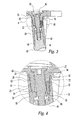
- A tibial prosthesis 2 includes
separate tray 10, keel 40, andstem 80 components able to be joined together to form a desired joint prosthesis configuration for replacing the articular surface of the proximal tibia. Thetray 10 includes generally planar top 12 andbottom 14 surfaces. The top surface 12 is configured to receive a bearing surface (not shown), such as a polyethylene bearing surface, as is known in the art. Thebottom surface 14 is configured to sit on the cut end of the proximal tibia. One ormore fins 16 extend radially along the bottom surface and project downwardly from the bottom surface. Thefins 16 are received in grooves cut in the proximal tibia to provide rotational resistance to the prosthesis. Thefins 16 also serve to strengthen thetray 10 by increasing the bending moment of inertia of the tray. Where further stability is desired, the tray provides for the modular attachment of additional components via aboss 18 extending downwardly from thebottom surface 14. Theboss 18 includes atop end 20 joined to thebottom surface 14 of thetray 10, a freely projectingbottom end 22, and an axis extending from thetop end 20 to thebottom end 22. Anouter wall 24 defines the exterior of theboss 18 and aninner bore 26 extends from thetop end 20 to thebottom end 22. The outer wall includes acylindrical mating portion 28, atapered mating portion 30, and a relieved,non-mating portion 29 therebetween. Analignment hole 32 is formed in thebottom end 22 and extends upwardly between theouter wall 24 and theinner bore 26. Thefins 16 can attach to theboss 18, or they can stop short of theboss 18 to leave agap 34. - An extension can be mounted on the tray to increase the stability of the tibial prosthesis on the bone. Such an extension can take the form of a stem, a fluted stem, or a keel. The extension can be symmetric or asymmetric. In the illustrative embodiment, a keel 40 is mated to the
boss 18 to increase both the rotational and bending stability of the tibial prosthesis on the bone. The keel 40 includes an elongate body having atop end 42 and abottom end 44 with an axis extending between them, and anouter wall 46. The keel includes at least onefin 48 extending axially along theouter surface 46 and projecting radially outwardly. The keel includes a firstaxial bore 50 extending downwardly from thetop end 42 and having a bore wall including acylindrical mating portion 52, atapered mating portion 54, and anend wall 56. Analignment hole 58 is formed in theend wall 56 and extends downwardly. The keel further includes a secondaxial bore 64 extending upwardly from thebottom end 44 and comprising atapered side wall 65. A keyedportal 66 communicates between the first 50 and second 64 axial bores. Theportal 66 includes a circularcentral opening 67 andside slots 68 forming a bayonet engagable member. Alternately, theportal 66 can be threaded for engaging a threaded member.. - The keel 40 engages the
tray 10 with theboss 18 received in the firstaxial bore 50, thetapered portion 30 of the boss seating on the tapered portion of thebore 54, and thecylindrical portion 28 of the boss being received by thecylindrical portion 52 of the bore in press-fit relationship to form a junction between thetray 10 and keel 40. The tapered portions aid in aligning the components as they are brought together. The cylindrical press-fit locks the components together. The cylindrical press-fit also provides a fluid tight seal to prevent material from migrating past the press-fit into or out of the junction. In the illustrative embodiment, therelieved portion 29 of the boss results in acircumferential gap 69 between theboss 18 and firstaxial bore 50 lying between the cylindrical 28, 52 and tapered 30,54 portions of the junction. Thetray 10 and keel 40 can be aligned by providing analignment pin 70 in one of thealignment holes pin 70 and thepin 70 is pressed into it. Thetray alignment hole 32 is slightly larger than the pin. As the components are brought together, they are prevented from seating until thetray alignment hole 32 engages thepin 70. Where agap 34 exists between theboss 18 andfins 16, thetop end 42 of the keel 40 can extend further up and fit into thegap 34 as shown in FIG. 4. - The junction of the present invention makes use of a press-fit which is advantageous over Morse taper-type arrangements used alone. The press fit allows the components to slide together in tight frictional engagement to create a fluid-tight seal and strong resistance to dislocation. The practicalities of machining result in a press-fit having a band, or area, of contact whereas a taper typically has line contact between the mating parts. The press-fit therefore provides a better seal and is more likely to prevent material from migrating across the press-fit boundary. Furthermore, the press-fit locking arrangement is not dependent on precise axial positioning between the components and therefore allows them to be positioned axially at a desired location, once initial press-fit engagement has been achieved. While a cylindrical press fit has been shown and lends itself to precise manufacturing, other cross-sectional shapes can be used in a sliding press-fit according to the invention. The junction also utilizes a taper engagement which provides for centering of the components during assembly and a positive stop to seating as the tapered portions bottom on one another. When the taper is fully seated, it provides increased bending strength to the junction due to the axial distance between the press fit and taper contacts. As shown in FIG. 4, the press-
fit - When assembled, the
tray 16 andkeel 48 fins are generally aligned with one another from top to bottom to project as a single fin, as best seen in FIG. 6. However, when the tray and keel are fully assembled, there remains anaxial gap 72 between thefins fit portion 52 above the taperedportion 54 and lockingpin 70. With this arrangement, and theaxial spacing 72 of thefins tray 10 and keel 40 outside of the junction. Any particles that may be produced by contact between the components are sealed in the junction so that they cannot migrate upward into the joint space. While it is within the scope of the invention to form the tapered portions above the cylindrical portions to provide the centering and locking functions, such an arrangement does not provide the same sealing characteristics. - A
stem 80 can be combined with thetray 10 and keel 40 assembly to provide further bending stability to the tibial prosthesis. Thestem 80 includes ashaft 82 having atop end 84 and abottom end 86. Thetop end 84 includes a taperedportion 88 and an axial threaded bore 90. The taperedportion 88 of the stem is received in the second axial bore 64 of the keel 40. This taper joint can also be provided as a self locking taper. Abolt 92 extends through theinner bore 26 of the boss and the portal 66 and threads into the threaded bore 90 of the stem to draw and hold the components together. Thehead 94 of the bolt is recessed into a counter bore 96 formed in the top surface 12 of the tray. - The invention further comprises an assembly tool for assembling modular joint components requiring a linear biasing force during assembly. The assembly tool is particularly well suited where high assembly forces are required. It is also well suited for a minimally invasive approach to the joint where an assembly force needs to be delivered to a small remote surgical space. The press-fit arrangement of the illustrative modular implant embodiment requires from 1000 to 2000 pounds of assembly force depending on the amount of interference between the press-fit components. For example, a 0.001 inch interference has been found to require 1000 pounds and a 0.002 inch interference has been found to require 2000 pounds. Likewise, when the components are positioned for assembly, it has been found that 0.050 inches of displacement are required to remove slack from the assembly and another 0.100 inches of displacement to fully engage the components.
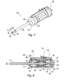
- FIGS. 7-10 depict an illustrative embodiment of an assembly tool capable of providing the force and displacement required for assembling the illustrative modular implant. A
compressor 100 includes ahandle 102 having proximal 101 and distal 103 ends, afirst shaft member 104 having a mountingend 106 rigidly attached to the handle and a workingend 108, and asecond shaft member 110 coaxially mounted within the first shaft member for axial translation relative to thefirst shaft member 104. The second shaft member includes afirst end 112 and asecond end 114. Thefirst end 112 includes anengagement tip 116 such as a threaded tip or a bayonet tip. The illustrative embodiment comprises a T-shapedbayonet tip 116 having a roundcentral portion 118 and a pair ofears 120 extending radially outwardly. Thebayonet tip 116 is generally the same shape as the portal 66 in the keel 40 and can be attached to the keel by inserting it into the portal 66 and rotating thesecond shaft member 110 one-quarter turn relative to the keel so that theears 120 extend beyond and grip the underside of the portal 66. A linear motor is located inside thehandle 102 and is connected to thesecond end 114 of thesecond shaft member 110 in axial force transmitting relation. The motor stores energy until it is needed to assemble the modular joint components. When activated, the motor causes thesecond shaft member 110 to translate toward the handle and thus thebayonet 116 tip to move toward the workingend 108 of thefirst shaft member 104. - In use, the modular joint components are initially engaged with the
boss 18 received within theaxial bore 50. The first 104 and second 110 shaft members are inserted along theinner bore 26 until thebayonet tip 116 of thesecond shaft member 110 extends through the portal 66. The tool is rotated so that theears 120 extend underneath the edges of the portal 66. At this point, thebayonet tip 116 positively engages the keel 40 and the workingend 108 of thefirst shaft member 104 rests against the bottom of the counter bore 96. The motor is actuated and the second shaft is withdrawn to draw thetray 10 and keel 40 into locking engagement. Thetool 100 is then rotated until theears 120 again align with the portal 66 and the tool is withdrawn. - A variety of motor mechanisms can be provided to generate the linear motion to operate the
tool 100. Examples include electric and pneumatic rotary motors coupled with rotary-to-linear transmissions, linear pneumatic pistons, and spring mechanisms. The illustrative embodiment depicts a linear spring motor comprising twentyBelleville washers 130 constrained by atelescoping core 132. First 134 and second 136 motion blocks abut opposite ends of the stack ofwashers 130. Absent other constraints, the first and second motion blocks 134, 136 andwashers 130 are free to translate axially within thehandle 102. Thesecond shaft member 110 extends through thesecond motion block 136 and telescoping core in axial sliding relationship. Thesecond end 114 of thesecond shaft member 110 is coupled to thefirst motion block 134 such that thesecond shaft member 110 moves with thefirst motion block 134. Anaxial opening 137 communicates from the exterior to the interior of the handle in alignment with thefirst motion block 134. The opening 137 permits a ram attached to an external press to be inserted into thehandle 102 to press against thefirst motion block 134 to compress the mechanism. - A linkage comprising a pair of links is positioned at each end of the handle to provide positive capture and release of the two motion blocks. The distal linkage comprises a
first link 138 and asecond link 140 pinned together 139 for rotation relative to one another. The first link is pinned at its opposite end to thefirst motion block 134 for rotation relative to thefirst motion block 134. The second link is pinned 135 at its opposite end to thedistal end 103 of the handle for rotation relative to the handle. The linkage is prevented from aligning at the point of singularity along its pivot axes, or top dead center, by atang 142 projecting from thesecond link 140 to contact apin 144 in the handle. Thetang 142 and pin 144 stop counter clockwise rotation of the linkage 2° before reaching the point of singularity. Afirst locking pin 146 slides in abore 148 in the side of thehandle 102 to engage acam 150 on thesecond link 140 to releasably block the linkage from rotating clockwise. Due to the shallow angle of the linkage in this position, large axial forces on the motion block impart relatively small forces against the lockingpin 146. A similar linkage comprising a pair oflinks proximal end 101 of the housing andsecond motion block 136. This linkage is similarly restrained against over rotation by atang 156 and pin 158 and is releasably blocked by asecond locking pin 162 sliding in abore 164. - A
trigger mechanism 170 is provided to simplify the sequential operation of the two lockingpins handle 102 and supports the other parts of the mechanism. Afirst lever 174 is pinned 178 for rotation in the housing 172 and includes aninput end 173 and anoutput end 175. Theoutput end 175 is connected to thefirst locking pin 146 via ayoke 182 surrounding aball end 184 formed on thelocking pin 146. Theinput end 173 of thefirst lever 174 is biased upwardly by aleaf spring 186, thereby biasing thelocking pin 146 downwardly into engagement with thecam 150. The firstlever pivot pin 178 is nearer theoutput end 175 so that there is a mechanical advantage proportional to the ratio of the input and output lengths. Therefore, forces applied at theinput end 173 are multiplied to ease manipulation of thelocking pin 146. Similarly, the second lever 176 is pinned 180 for rotation in the housing 172 and includes aninput end 187 and anoutput end 188. Theoutput end 188 is connected to thesecond locking pin 162 via ayoke 190 surrounding aball end 192 formed on thelocking pin 162. Theinput end 187 of the second lever 176 is biased upwardly by aleaf spring 194, thereby biasing thelocking pin 162 downwardly into engagement with thecam 160. Atrigger 196 is pinned 198 for rotation in the trigger housing 172 and overlies the input ends 173, 187 of the twolevers 174, 176. Thetrigger 196 includes afirst contact 200 projecting downwardly to engage theinput end 173 of thefirst lever 174. Thetrigger 196 includes asecond contact 202 projecting downwardly to engage theinput end 187 end of the second lever 176. Thesecond contact 202 is spaced, relative to thefirst contact 200, so that it does not activate the second lever 176 until after thefirst lever 174 has been fully activated. - In use, the
assembly tool 100 is held with its distal end down so that gravity moves thesecond motion block 136 axially downwardly toward the center of the mechanism. As thesecond motion block 136 moves, the proximal linkage rotates clockwise with the end of thesecond locking pin 162 riding on thecam 160. When the linkage is straightened to its limits, the lockingpin 162 slips over the end of thecam 160 and snaps into position to lock thesecond motion block 136. Thefirst motion block 134 is now axially pressed toward the center of the mechanism with an external press to compress thewashers 130. As thefirst motion block 134 moves, the distal linkage rotates counterclockwise with the end of thefirst locking pin 146 riding on thecam 150. When the linkage is straightened to its limits, thepin 146 slips over the end of thecam 150 and snaps into position to lock thefirst motion block 134. The precharged assembly tool is now in condition to be used to assemble the modular joint components. Thetool 100 is engaged with the implant components. Thetrigger 196 is pressed to activate the tool. As thetrigger 196 rotates about itspivot pin 198, thefirst contact 200 presses theinput end 173 of thefirst lever 174 causing theoutput end 175 to withdraw thefirst locking pin 146 and release the distal linkage. The distal linkage rotates clockwise and permits thefirst motion block 134 to spring distally. Thesecond shaft member 110 moves with thefirst motion block 134 and draws the modular components together. The spring action of the tool snaps the press-fit junction into engagement. With thefirst motion block 134 released, the remaining spring tension still exceeds the minimum required to seat the press-fit junction. This ensures that the junction is fully seated but makes it difficult to disengage thetool 100 from the joint components. Therefore, continued pressing of the trigger causes thesecond contact 202 to press against theinput end 187 of the second lever 176 to withdraw thesecond locking pin 162. This permits thesecond motion block 136 to spring proximally and release the remaining spring tension. Thetool 100 can now be disengaged from the joint components. The two stage trigger release happens quickly and is transparent to the user who is simply required to fully depress the trigger once to cause the separate sequential releases. - In clinical use, an incision is made in the knee joint. For a minimally invasive surgical approach according to the present invention, an incision is made on one of the medial and lateral sides of the knee joint to expose the joint surfaces while avoiding compromising the soft tissue of the suprapatellar pouch. Next, resection instruments are introduced through the incision to prepare the proximal tibial bone and form a keel receiving recess. Ideally, only the minimum amount of bone required to provide a stable flat surface on the tibia is removed. The illustrative modular tibial component has a low profile. Because of this low profile and modularity, the incision can be quite small and need only be large enough to allow passage of the individual components. The present investigators have found that a tray component having an overall height less than 18mm can be inserted through such a minimally invasive surgical incision and engage the tibia where the minimum amount of bone has been removed. The keel component of the present invention can be manipulated into the prepared joint space because it lacks the large top surface of the tray. Likewise, the low profile and modularity of the components permit the patella to remain in its anatomic orientation relative to the femur to further reduce the trauma experienced by the joint during surgery and aid recovery and ultimate outcome from the procedure. The keel is manipulated through the incision and placed into the recess. The tray is then manipulated through the incision and engaged with the keel. The assembly instrument is engaged with the tray and keel and activated to draw the components together to engage the press-fit and seat the tapered portions of the modular junction.
- It will be understood by those skilled in the art that the foregoing has described illustrative embodiments of the present invention and that variations may be made to these embodiments without departing from the spirit and scope of the invention defined by the appended claims. The various aspects of the present invention are applicable to a variety of bone implants in addition to the illustrative tibial implant. Likewise, where male/female engaging portions have been depicted, the male and female components may be reversed and still be within the anticipated scope of the invention. Likewise the arrangement of the multiple incongruous junction shapes can be changed while keeping within the invention. For example, the illustrative embodiment depicts a junction including a press-fit and then a taper. The invention contemplates reversing that order so that the taper comes before the press-fit.
Claims (50)
- A tibial component of a knee prosthesis comprising a tray having substantially planar top and bottom surfaces and an extension forming an elongate body having a top end and a bottom end, one of the tray and extension including an outwardly projecting boss, the boss having an outer wall including a cylindrical portion and a tapered portion, the other of the tray and extension including an inwardly extending bore forming a bore wall, the bore wall including a cylindrical portion and a tapered portion, the extension being removably engagable with the tray with the boss received in the bore, the tapered portion of the boss seating on the tapered portion of the bore and the cylindrical portion of the boss being received by the cylindrical portion of the bore in press-fit relationship to form a junction between the tray and extension.
- The tibial component of claim 1 wherein the tapered portions form a locking taper.
- The tibial component of claim 1 wherein the boss extends downwardly from the bottom surface of the tray and the bore comprises a first axial bore formed in the extension extending from the top end toward the bottom end of the extension.
- The tibial component of claim 3 wherein the tapered portion of the boss is formed below the cylindrical portion of the boss and the tapered portion of the bore is formed below the cylindrical portion of the bore so that the tapered seating portion of the junction is below the cylindrical press-fit portion of the junction.
- The tibial component of claim 4 wherein the cylindrical press-fit between the boss and first axial bore seals the bore to prevent material from entering or leaving the portion of the bore below the press-fit.
- The tibial component of claim 1 wherein the tray and extension are spaced from one another everywhere except at the cylindrical and taper seating portions of the junction.
- The tibial component of claim 1 wherein the tray further comprises at least one fin extending along the bottom surface and projecting downwardly from the bottom surface, and the extension further comprises at least one fin projecting outwardly, the fins being generally aligned with one another from top to bottom to project as a single fin but being in axial spaced relationship so that they do not contact.
- The tibial component of claim 4 wherein the boss is relieved between the cylindrical and tapered portions so that there is clearance between the boss and bore between the cylindrical and tapered portions.
- The tibial component of claim 1 further comprising rotational alignment means for aligning the extension and tray in a predetermined relationship for assembly, the alignment means being formed within the junction.
- The tibial component of claim 9 wherein the rotational alignment means is positioned within the junction relative to the cylindrical press-fit portion so that it is sealed within the junction to prevent migration of material from the rotational alignment means outside of the junction.
- The tibial component of claim 9 wherein the rotational alignment means comprises a pin received in a hole.
- The tibial component of claim 11 wherein the pin is located in the first axial bore and the pin is received by a hole formed in the boss.
- The tibial component of claim 3 wherein the extension comprises a keel and includes a second axial bore extending from the bottom end toward the top end to communicate with the first axial bore, the second axial bore forming a tapered inner wall for receiving a stem extension.
- The tibial component of claim 13 wherein the tray includes a bore extending from the top surface downwardly through the boss in communication with the first axial bore, the tray bore receiving a bolt in engagement with one of the keel and stem extension.
- A bone joint implant comprising:a first component having top and bottom surfaces; anda second component having a top end and a bottom end and an axis from the top end to the bottom end, the second component being removably affixed to the bottom of the first component, one of the fist and second components including a male junction element having an outer wall including a first seating portion having a first shape and a second seating portion having a second shape, the other of the first and second components including a female junction having an inner wall including a first seating portion having a first shape congruent with the male first seating portion shape and a second seating portion having a second shape congruent with the male second seating portion shape, the first and second seating portion shapes being incongruent, the second component being releasably joined with the first component with the male first and second seating portions being in close fitting relationship with the female first and second seating portions.
- The bone joint implant of claim 15 wherein one of the first and second seating portions comprise a sealing junction to prevent the passage of material across the junction.
- The bone joint implant of claim 15 wherein one of the first and second seating portions comprise a press-fit junction.
- The bone joint implant of claim 17 wherein the first seating portions comprise a taper joint and the second seating portions comprise a cylindrical press-fit joint.
- The bone joint implant of claim 18 wherein the taper joint is a locking taper.
- The bone joint implant of claim 18 wherein the cylindrical press-fit joint seals a space adjacent the taper joint to prevent the outward migration of material from the taper joint.
- The bone joint implant of claim 15 wherein at least one of the first and second components includes at least one fin.
- The bone joint implant of claim 21 wherein the first component includes at least one fin extending radially along its bottom surface and projecting downwardly and the second component includes an outer surface and at least one fin extending axially along the outer surface and projecting radially outwardly, the fins on the two components aligning from top to bottom to project as a single fin, the fins on the two components being axially spaced from one another.
- The bone joint implant of claim 15 wherein the first component comprises a tibial tray component and the second component comprises a tibial keel component.
- A tibial component of a knee prosthesis comprising:a tray having top and bottom surfaces and an axis extending between them, at least one fin extending radially outwardly along the bottom surface and projecting axially downwardly; anda keel having a top end and a bottom end and an axis from the top end to the bottom end generally parallel to the tray axis, the keel forming an outer surface and being removably affixed to the bottom of the tray, the keel further comprising at least one fin extending axially along the outer surface and projecting radially outwardly, the tray and keel fins being generally axially aligned with one another from top to bottom to project as a single fin but being in axial spaced relationship so that they do not contact.
- The tibial component of claim 24 wherein the tray includes a boss projecting downwardly from the bottom surface and the keel includes an axial bore extending from the top end toward the bottom end, the boss being received in the axial bore to attach the keel to the tray, the at least one fin on the bottom of the tray being spaced from the boss to form a gap between the boss and tray fin, the keel seating on the boss so that a portion of the keel fits within the gap.
- The tibial component of claim 25 wherein the at least one keel fin is notched downwardly, parallel to the at least one tray fin so that the tray fin projects downwardly into the notch parallel to the keel fin, without touching the keel fin.
- A tibial component of a knee prosthesis comprising:a tray having top and bottom surfaces; anda keel having a top end and a bottom end and an axis from the top end to the bottom end, the keel being engagable with the bottom of the tray, the keel and tray forming a junction including a rotational alignment means for aligning the keel and tray in a predetermined relationship for assembly, the alignment means being sealed within the junction to prevent migration of material from the rotational alignment means outside of the junction.
- The tibial component of claim 27 wherein the rotational alignment means comprises a pin received in a hole.
- The tibial component of claim 28 wherein the keel includes a bore extending from the top end downwardly and the tray includes a boss extending downwardly from the bottom surface, the boss being received in the bore to form the junction between the tray and keel, the pin being located in the bore and the hole being formed in the boss.
- A tool for assembling first and second modular joint components, the tool comprising first and second tool elements connectable to the first and second joint components respectively, the tool containing stored energy able to bias the first and second tool elements relative to one another upon activation of the tool to draw the first and second modular joint components into seating relationship.
- The tool of claim 31 wherein tool energy is released quickly to rapidly snap the components together in press-fit relationship.
- The tool of claim 30 wherein the first tool element comprises a shaft having an end for connecting to one of the first and second joint components, the end comprising a connecting element selected from the group consisting of a threaded connecting element and a T-shaped connecting element.
- The tool of claim 30 further comprising a spring powered linear motor for biasing the first and second tool elements.
- The tool of claim 33 further comprising:a spring compressible to store a biasing energy;a first linkage attached to a first end of the spring; anda second linkage attached to a second end of the spring, the first linkage being actuable to release the first end of the spring to release a first portion of the stored biasing energy to move the first and second tool elements relative to one another, the second linkage being actuable to release the second end of the spring to release a second portion of the stored biasing energy.
- The tool of claim 34 further comprising a trigger mounted on the handle, the trigger able to actuate the first and second linkages sequentially with a single press of the trigger.
- The tool of claim 35 wherein the trigger has a first end and a second end, the trigger being pinned to the housing for rotation at the first end and the trigger further comprising first and second linkage contacts, the trigger being rotatable about its first end to bring the first and second contacts into sequential contact with the linkages to sequentially actuate the first and second linkages.
- The tool of claim 36 wherein the trigger sequentially actuates the linkages in a single, unidirectional trigger motion.
- The tool of claim 33 wherein the motor comprises a stack of Belleville washers.
- A tool for assembling first and second modular joint components, the tool comprising:a handle;a first shaft member mounted on the handle for axial translation and being engagable with the first joint component in axial force transmitting relationship;a second shaft member fixed to the handle and being engagable with the second joint component in axial force transmitting relationship;a motor engaging the first member to impart axial force to the first member to move the joint components into engagement, the tool storing energy to drive the motor.
- The tool of claim 39 wherein the motor comprises a spring compressible to store the energy to drive the motor.
- The tool of claim 40 wherein the spring comprises a series of Belleville washers.
- The tool of claim 40 wherein the first and second members comprise elongated shafts, the first member being coaxially mounted with the second member.
- The tool of claim 42 further comprising a first linkage attached to a first end of the spring, the first linkage being actuable to release the first end of the spring to release a first portion of the stored energy to axially move the first member relative to the second member, the second linkage being actuable to release the second end of the spring to release a second portion of the stored energy.
- The tool of claim 43 wherein the release of the second end of the spring restores the spring to an uncompressed state.
- The tool of claim 43 wherein the first and second linkages each comprise a pair of joined rotating links wherein the rotation of the links is blocked by a locking pin slidingly mounted in the handle adjacent each linkage.
- The tool of claim 45 further comprising a trigger and a pair of levers, the levers each having a first end and a second end, each lever being pinned to the handle by a pivot pin, the first end of each lever engaging one of the linkage locking pins, the trigger being pinned to the handle by a pivot pin, the trigger overlying the second ends of both levers, the trigger rotating about its pivot pin to sequentially depress the second ends to sequentially actuate the linkages.
- A method for assembling a modular joint component, the method comprising the steps of:providing first and second modular joint components having corresponding first and second engagement portions;providing a tool having first and second tool elements, the tool containing stored energy able to bias the first and second tool elements relative to one another;aligning the first and second engagement portions;engaging the tool first and second tool elements with the first and second joint components, activating the tool to release the stored energy to bias the first and second tool elements and draw the first and second joint components together.
- The method of claim 47 wherein the stored energy is provided by at least one precompressed spring.
- The method of claim 47 wherein the first and second joint components form a press fit engagement when they are drawn together.
- The method of claim 49 wherein the first and second joint components comprise a tibial knee prosthesis further comprising a tray having substantially planar top and bottom surfaces and a keel forming an elongate body having a top end and a bottom end, one of the tray and keel including an outwardly projecting boss, the boss having an outer wall including a cylindrical portion and a tapered portion, the other of the tray and keel including an inwardly extending bore forming a bore wall, the bore wall including a cylindrical portion and a tapered portion, the keel being removably engagable with the tray with the boss received in the bore, the tapered portion of the boss seating on the tapered portion of the bore and the cylindrical portion of the boss being received by the cylindrical portion of the bore in press-fit relationship to form a junction between the tray and keel.
Applications Claiming Priority (2)
| Application Number | Priority Date | Filing Date | Title |
|---|---|---|---|
| US10/369,331 US7182786B2 (en) | 2002-04-25 | 2003-02-18 | Modular bone implant, tool, and method |
| US369331 | 2003-02-18 |
Publications (3)
| Publication Number | Publication Date |
|---|---|
| EP1449500A2 true EP1449500A2 (en) | 2004-08-25 |
| EP1449500A3 EP1449500A3 (en) | 2004-10-20 |
| EP1449500B1 EP1449500B1 (en) | 2007-06-20 |
Family
ID=32736424
Family Applications (1)
| Application Number | Title | Priority Date | Filing Date |
|---|---|---|---|
| EP04250511A Expired - Lifetime EP1449500B1 (en) | 2003-02-18 | 2004-01-30 | Modular bone implant |
Country Status (7)
| Country | Link |
|---|---|
| US (3) | US7182786B2 (en) |
| EP (1) | EP1449500B1 (en) |
| JP (1) | JP4704692B2 (en) |
| AU (1) | AU2004200394B2 (en) |
| CA (1) | CA2455377C (en) |
| DE (1) | DE602004007050T2 (en) |
| ES (1) | ES2287649T3 (en) |
Cited By (6)
| Publication number | Priority date | Publication date | Assignee | Title |
|---|---|---|---|---|
| EP1522284A2 (en) * | 2003-10-09 | 2005-04-13 | Zimmer Technology, Inc. | Modular bone implant and tools |
| US8157867B2 (en) | 2004-07-09 | 2012-04-17 | Zimmer, Inc. | Trochlear groove implants and related methods and instruments |
| US8236060B2 (en) | 2003-12-30 | 2012-08-07 | Zimmer, Inc. | Tethered joint bearing implants and systems |
| US8241367B2 (en) | 2002-04-25 | 2012-08-14 | Zimmer, Inc. | Modular bone implant, tool, and method |
| US8460391B2 (en) | 2002-05-24 | 2013-06-11 | Zimmer, Inc. | Modular femoral components for knee arthroplasty |
| US8690951B2 (en) | 2005-11-18 | 2014-04-08 | Zimmer, Gmbh | Base platform for an artificial joint |
Families Citing this family (74)
| Publication number | Priority date | Publication date | Assignee | Title |
|---|---|---|---|---|
| US20020120340A1 (en) * | 2001-02-23 | 2002-08-29 | Metzger Robert G. | Knee joint prosthesis |
| US7892288B2 (en) | 2001-08-27 | 2011-02-22 | Zimmer Technology, Inc. | Femoral augments for use with knee joint prosthesis |
| US20030065397A1 (en) | 2001-08-27 | 2003-04-03 | Hanssen Arlen D. | Prosthetic implant support structure |
| US20040162619A1 (en) * | 2001-08-27 | 2004-08-19 | Zimmer Technology, Inc. | Tibial augments for use with knee joint prostheses, method of implanting the tibial augment, and associated tools |
| EP2359775B1 (en) | 2002-02-20 | 2012-12-26 | Zimmer, Inc. | Knee arthroplasty prosthesis |
| US20040102852A1 (en) * | 2002-11-22 | 2004-05-27 | Johnson Erin M. | Modular knee prosthesis |
| US7153326B1 (en) * | 2003-06-19 | 2006-12-26 | Biomet Manufacturing Corp. | Method and apparatus for use of an offset stem connection |
| US6843274B1 (en) | 2003-06-25 | 2005-01-18 | Air Systems International, Inc. | Electrically conductive confined space ventilator conduit formed of conductive polymer, electrical grounding circuit for ventilation system using same, and methods of using and forming same |
| US7727281B2 (en) * | 2003-12-08 | 2010-06-01 | Ortho Development Corporation | Modular femoral knee stem extender |
| US7935120B2 (en) * | 2004-04-30 | 2011-05-03 | Zimmer Technology, Inc. | Posterior femur rough cut guide for minimally invasive knee arthroplasty |
| US20060142869A1 (en) * | 2004-12-23 | 2006-06-29 | Gross Thomas P | Knee prosthesis |
| US20060200158A1 (en) * | 2005-01-29 | 2006-09-07 | Farling Toby N | Apparatuses and methods for arthroplastic surgery |
| US7998217B1 (en) | 2005-02-02 | 2011-08-16 | Biomet Manufacturing Corp. | Modular offset stem implants |
| US20060247664A1 (en) * | 2005-03-08 | 2006-11-02 | California Institute Of Technology | Micromachined tissue anchors for securing implants without sutures |
| AU2006223238B2 (en) | 2005-03-14 | 2011-09-29 | Inbone Technologies, Inc. | Ankle replacement system |
| US7357817B2 (en) * | 2005-05-19 | 2008-04-15 | Howmedica Osteonics Corp. | Modular keel tibial component |
| US7695519B2 (en) * | 2005-07-08 | 2010-04-13 | Howmedica Osteonics Corp. | Modular tibial baseplate |
| US7766969B2 (en) * | 2005-12-05 | 2010-08-03 | Zimmer, Inc. | Modular progressive implant for a joint articulation surface |
| US9241800B2 (en) * | 2005-12-21 | 2016-01-26 | Orthopaedic International Inc. | Tibial component with a conversion module for a knee implant |
| US7771484B2 (en) * | 2006-02-28 | 2010-08-10 | Howmedica Osteonics Corp. | Modular tibial implant |
| WO2007114841A1 (en) * | 2006-04-04 | 2007-10-11 | Smith & Nephew, Inc. | Trial coupler systems and methods |
| US7842093B2 (en) | 2006-07-18 | 2010-11-30 | Biomet Manufacturing Corp. | Method and apparatus for a knee implant |
| US7691150B2 (en) * | 2006-12-15 | 2010-04-06 | Zimmer Technology, Inc. | Modular plate and keel provisionals |
| US8163028B2 (en) | 2007-01-10 | 2012-04-24 | Biomet Manufacturing Corp. | Knee joint prosthesis system and method for implantation |
| US8187280B2 (en) | 2007-10-10 | 2012-05-29 | Biomet Manufacturing Corp. | Knee joint prosthesis system and method for implantation |
| US8328873B2 (en) | 2007-01-10 | 2012-12-11 | Biomet Manufacturing Corp. | Knee joint prosthesis system and method for implantation |
| US8562616B2 (en) | 2007-10-10 | 2013-10-22 | Biomet Manufacturing, Llc | Knee joint prosthesis system and method for implantation |
| US8157869B2 (en) | 2007-01-10 | 2012-04-17 | Biomet Manufacturing Corp. | Knee joint prosthesis system and method for implantation |
| US20080255574A1 (en) * | 2007-04-13 | 2008-10-16 | Zimmer Technology, Inc. | Instrument for insertion of prosthetic components |
| US8177849B2 (en) * | 2007-05-07 | 2012-05-15 | Zimmer, Inc. | Methods and apparatuses for attaching tissue to orthopaedic implants |
| US8657820B2 (en) | 2009-10-12 | 2014-02-25 | Tornier, Inc. | Bone plate and keel systems |
| US20110087229A1 (en) * | 2009-10-12 | 2011-04-14 | University Of Utah | Bone fixation and compression systems |
| US8439593B2 (en) * | 2009-11-10 | 2013-05-14 | Imds Corporation | Quarter turn locking mechanism |
| EP3470020A3 (en) * | 2010-01-29 | 2019-09-18 | Smith & Nephew, Inc. | Cruciate-retaining knee prosthesis |
| US8444699B2 (en) * | 2010-02-18 | 2013-05-21 | Biomet Manufacturing Corp. | Method and apparatus for augmenting bone defects |
| US8221432B2 (en) | 2010-03-05 | 2012-07-17 | Biomet Manufacturing Corp. | Method and apparatus for implanting a modular femoral hip |
| US8529569B2 (en) | 2010-03-05 | 2013-09-10 | Biomet Manufacturing, Llc | Method and apparatus for preparing a proximal femur |
| US8419743B2 (en) | 2010-03-05 | 2013-04-16 | Biomet Manufacturing Corp. | Assembly tool for modular implants and associated method |
| US8679130B2 (en) | 2010-03-05 | 2014-03-25 | Biomet Manufacturing, Llc | Guide assembly for lateral implants and associated methods |
| US8460393B2 (en) | 2010-03-05 | 2013-06-11 | Biomet Manufacturing Corp. | Modular lateral hip augments |
| US8333807B2 (en) * | 2010-03-05 | 2012-12-18 | Biomet Manufacturing Corp. | Method and apparatus for trialing and implanting a modular femoral hip |
| US8932364B2 (en) * | 2010-07-14 | 2015-01-13 | Howmedica Osteonics Corp. | Prosthetic knee void filers with splined fixation |
| US8728167B2 (en) | 2011-01-10 | 2014-05-20 | Howmedica Osteonics Corp. | Bicruciate retaining tibial baseplate design and method of implantation |
| US8911501B2 (en) | 2011-12-29 | 2014-12-16 | Mako Surgical Corp. | Cruciate-retaining tibial prosthesis |
| US9668871B2 (en) | 2011-12-29 | 2017-06-06 | Mako Surgical Corp. | Cruciate-retaining tibial prosthesis |
| WO2013148229A1 (en) | 2012-03-30 | 2013-10-03 | Depuy Products, Inc. | Stemless humeral component and associated surgical instruments and methods |
| US9345578B2 (en) | 2013-02-22 | 2016-05-24 | Stryker Corporation | Bicruciate retaining tibial implant system |
| US11007063B2 (en) | 2013-03-11 | 2021-05-18 | Catalyst Orthoscience Inc. | Offset reamers |
| US9814588B2 (en) | 2015-08-10 | 2017-11-14 | Catalyst Orthoscience Inc. | Glenoid arthroplasty with multi-directional fixation |
| US9775716B2 (en) * | 2013-03-11 | 2017-10-03 | Catalyst Orthoscience Inc. | Glenoid arthroplasty |
| US10973646B2 (en) | 2013-03-11 | 2021-04-13 | Catalyst Orthoscience Inc. | Stabilized drill guide |
| US20170319348A1 (en) | 2015-08-10 | 2017-11-09 | Catalyst Orthoscience Inc. | Arthroplasty prostheses with multi-axis fixation |
| US9814471B2 (en) | 2013-03-11 | 2017-11-14 | Catalyst Orthoscience Inc. | Glenoid arthroplasty and offset reamers |
| US9949839B2 (en) | 2013-03-13 | 2018-04-24 | Wright Medical Technology, Inc. | Revision implant augments, systems, and methods |
| US9603649B2 (en) * | 2013-03-15 | 2017-03-28 | Depuy Ireland Unlimited Company | Instruments for use in disassembling implants |
| US9289306B2 (en) | 2013-03-15 | 2016-03-22 | Catalyst Orthopaedics Llc | Humeral arthroplasty |
| USD735338S1 (en) | 2013-10-31 | 2015-07-28 | Catalyst Orthopaedics Llc | Humeral component for shoulder arthroplasty |
| CA2985837A1 (en) * | 2014-05-23 | 2015-11-26 | Robert Lye | Integrated skeletal implant and its method of surgical implantation |
| CA2889245C (en) * | 2014-11-07 | 2018-05-01 | Kian-Ming Wong | Talar dome fixation stem |
| DE102015209520B3 (en) * | 2015-05-22 | 2016-10-27 | Peter Brehm Holding Gmbh & Co. Kg | Modular stem endoprostheses |
| US10722381B2 (en) * | 2015-08-27 | 2020-07-28 | Hip Innovation Technology, LLC | Surgical trays, instruments and methods for removing components of a hip replacement prosthesis |
| US10182917B2 (en) | 2016-04-11 | 2019-01-22 | Arthrex, Inc. | Components for artificial joints |
| US9907655B2 (en) | 2016-06-17 | 2018-03-06 | Arthrex, Inc. | Components for artificial joints |
| US10231840B2 (en) | 2016-07-27 | 2019-03-19 | Howmedica Osteonics Corp. | Low profile tibial baseplate with fixation members |
| US10136998B2 (en) | 2016-08-30 | 2018-11-27 | Wright Medical Technology, Inc. | Revision total ankle implants |
| US11141276B2 (en) | 2017-01-20 | 2021-10-12 | Biomet Manufacturing, Llc | Modular augment component |
| US11406502B2 (en) | 2017-03-02 | 2022-08-09 | Optimotion Implants LLC | Orthopedic implants and methods |
| US10905436B2 (en) | 2017-03-02 | 2021-02-02 | Optimotion Implants, Llc | Knee arthroplasty systems and methods |
| USD901013S1 (en) | 2019-08-12 | 2020-11-03 | Ortho Development Corporation | Porous implant |
| US11565021B1 (en) | 2019-08-12 | 2023-01-31 | Ortho Development Corporation | Composite structure porous implant for replacing bone stock |
| USD901014S1 (en) | 2019-08-12 | 2020-11-03 | Ortho Development Corporation | Porous implant |
| USD901012S1 (en) | 2019-08-12 | 2020-11-03 | Ortho Development Corporation | Porous implant |
| US11498124B1 (en) | 2019-11-25 | 2022-11-15 | Ortho Development Corporation | Method for sintering porous structures from powder using additive manufacturing |
| CN113876473B (en) * | 2021-08-31 | 2022-08-23 | 浙江大学 | External pin nailing device for elbow joint prosthesis pin shaft and working method of external pin nailing device |
Citations (8)
| Publication number | Priority date | Publication date | Assignee | Title |
|---|---|---|---|---|
| US2725878A (en) * | 1954-09-20 | 1955-12-06 | Union Broach Co Inc | Surgical mallet structure |
| US5147407A (en) * | 1990-10-20 | 1992-09-15 | Taeger Karl H | Prosthetic cup member |
| EP0552950A1 (en) * | 1992-01-21 | 1993-07-28 | Howmedica International Inc. | Tibial element for a replacement knee prosthesis |
| US5364397A (en) * | 1993-06-01 | 1994-11-15 | Zimmer, Inc. | Spinal coupler seater with dual jaws and an independent plunger |
| US5609641A (en) * | 1995-01-31 | 1997-03-11 | Smith & Nephew Richards Inc. | Tibial prosthesis |
| EP1059070A2 (en) * | 1999-06-10 | 2000-12-13 | Aesculap AG & Co. KG | Prosthesis shaft |
| US6214052B1 (en) * | 1999-01-19 | 2001-04-10 | Sulzer Orthopedics Inc. | Tibial component with a reversible, adjustable stem |
| WO2002007647A2 (en) * | 2000-07-20 | 2002-01-31 | Depuy Orthopaedics, Inc. | Modular connection for orthopedic component |
Family Cites Families (162)
| Publication number | Priority date | Publication date | Assignee | Title |
|---|---|---|---|---|
| US2682265A (en) | 1951-12-28 | 1954-06-29 | Marie B Collison | Trochanteric plate and artificial femoral head |
| US2785673A (en) | 1952-05-06 | 1957-03-19 | Anderson Roger | Femoral prosthesis |
| US3943576A (en) | 1971-10-14 | 1976-03-16 | Sivash Konstantin Mitrofanovic | Artificial hip joint made from two different surgical alloys |
| US3848272A (en) | 1972-01-13 | 1974-11-19 | United States Surgical Corp | Artificial hip joint |
| SU440014A1 (en) | 1972-05-04 | 1978-08-05 | Саратовский государственный медицинский институт | Endoprosthesis of proximal end of thighbone |
| SU428623A1 (en) | 1972-05-04 | 1976-07-05 | Саратовский государственный медицинский институт | Collapsible artificial hip joint |
| AT337885B (en) | 1973-04-12 | 1977-07-25 | Feldmuehle Anlagen Prod | IMPLANTABLE ARTIFICIAL JOINT REPLACEMENT |
| DE2340546A1 (en) | 1973-08-10 | 1975-02-27 | Pfaudler Werke Ag | METALLIC IMPLANT AND PROCEDURE FOR ITS MANUFACTURING |
| US3906550A (en) | 1973-12-27 | 1975-09-23 | William Rostoker | Prosthetic device having a porous fiber metal structure |
| JPS5223514B2 (en) | 1974-09-25 | 1977-06-24 | ||
| US4051559A (en) | 1974-12-27 | 1977-10-04 | Mahay & Cie | Total prosthesis of the hip |
| US4086701A (en) | 1975-04-07 | 1978-05-02 | Kyoto Ceramic Kabushiki Kaisha | Device for implanting an artificial endosseous element of ceramics and an implant method for use of the same |
| US4259072A (en) | 1977-04-04 | 1981-03-31 | Kyoto Ceramic Co., Ltd. | Ceramic endosseous implant |
| DE2734249A1 (en) | 1977-07-29 | 1979-02-08 | Bayer Ag | THIGH NECK PROSTHESIS |
| IE50750B1 (en) | 1980-03-11 | 1986-07-09 | Howmedica | A set for assembly into a modular prosthesis |
| US4304011A (en) | 1980-08-25 | 1981-12-08 | Whelan Iii Edward J | Semi-constrained metacarpophalangeal prosthesis |
| DE3205577C2 (en) | 1981-02-23 | 1989-11-02 | Inc. Zweigniederlassung Kiel 2314 Schönkirchen Howmedica International | Endoprosthesis for femoral or tibial articular bone parts and adjacent femoral or tibial bone sections |
| EP0059070A1 (en) | 1981-02-24 | 1982-09-01 | Spencer Clark Metal Industries Limited | Steel corrosion protected members |
| EP0077868A1 (en) | 1981-10-26 | 1983-05-04 | Nunzio Godoli | Hip prosthesis as expanding femoral component |
| US4624673A (en) | 1982-01-21 | 1986-11-25 | United States Medical Corporation | Device system for dental prosthesis fixation to bone |
| CA1237553A (en) | 1982-01-21 | 1988-06-07 | Benjamin S. Meyer | Artificial joint fixation to bone and sleeve therefor |
| US4790854A (en) | 1982-02-17 | 1988-12-13 | Howmedica International Inc. | Bone prosthesis assembly |
| US4578081A (en) | 1982-02-17 | 1986-03-25 | Howmedica International, Inc. | Bone prosthesis |
| SE459844B (en) | 1983-08-12 | 1989-08-14 | Idea Ab | DEVICE FOR FIXING A LED PROTEST |
| DE3334058C2 (en) | 1983-09-21 | 1985-07-25 | Ulrich Dr.-Ing. 5600 Wuppertal Witzel | Thigh section for a hip joint prosthesis |
| US5190546A (en) | 1983-10-14 | 1993-03-02 | Raychem Corporation | Medical devices incorporating SIM alloy elements |
| DE3340767A1 (en) | 1983-11-08 | 1985-05-15 | Mecron Medizinische Produkte Gmbh, 1000 Berlin | KIT FOR A RESECTION PROSTHESIS |
| WO1985003426A1 (en) | 1984-02-09 | 1985-08-15 | Joint Medical Products Corporation | Apparatus for affixing a prosthesis to bone |
| US4846839A (en) | 1984-02-09 | 1989-07-11 | Joint Medical Products Corporation | Apparatus for affixing a prosthesis to bone |
| DE3435243C1 (en) | 1984-09-26 | 1986-03-13 | S + G Implants GmbH, 2400 Lübeck | Femoral prosthesis part of a knee joint endoprosthesis |
| FR2580926B1 (en) | 1985-04-24 | 1991-04-12 | Montagne Patrick | FEMALE PROSTHESIS WITH INDEPENDENT MODULAR COLLAR AND VARIABLE IN LENGTH AND DIRECTION FOR IMPLANTATIONS OF SINGLE FEMALE PROSTHESES OR TOTAL HIP PROSTHESES |
| DE3568134D1 (en) | 1985-05-23 | 1989-03-16 | Schweiz Lab Exper Chirurgie | Self-locking stemmed component for a joint endo-prosthesis |
| DE3625520A1 (en) | 1986-03-15 | 1987-09-17 | Mecron Med Prod Gmbh | BONE IMPLANT |
| DE8611697U1 (en) | 1986-04-25 | 1986-06-19 | Mecron Medizinische Produkte Gmbh, 1000 Berlin | Kit for a stem prosthesis |
| US5344457A (en) | 1986-05-19 | 1994-09-06 | The University Of Toronto Innovations Foundation | Porous surfaced implant |
| US5314479A (en) | 1986-08-15 | 1994-05-24 | Depuy Inc. | Modular prosthesis |
| US5080685A (en) | 1986-08-15 | 1992-01-14 | Boehringer Mannheim Corporation | Modular hip prosthesis |
| EP0257359B1 (en) | 1986-08-15 | 1991-11-27 | Boehringer Mannheim Corporation | Modular hip prosthesis |
| US4822366A (en) | 1986-10-16 | 1989-04-18 | Boehringer Mannheim Corporation | Modular knee prosthesis |
| DE8703491U1 (en) | 1987-03-09 | 1987-04-23 | Waldemar Link Gmbh & Co, 2000 Hamburg, De | |
| DE8708500U1 (en) | 1987-06-12 | 1988-04-14 | Mecron Medizinische Produkte Gmbh, 1000 Berlin, De | |
| US5194066A (en) | 1988-01-11 | 1993-03-16 | Boehringer Mannheim Corporation | Modular joint prosthesis |
| US4851007A (en) | 1988-03-18 | 1989-07-25 | Gray Frank B | Femoral component for a hip prosthesis |
| US4950298A (en) | 1988-04-08 | 1990-08-21 | Gustilo Ramon B | Modular knee joint prosthesis |
| US5108437A (en) | 1988-09-14 | 1992-04-28 | Pfizer Hospital Products Group, Inc. | Modular prosthesis |
| GB2222776B (en) | 1988-09-15 | 1992-12-02 | Mclardy Smith Peter David | A prosthesis |
| GB2225722B (en) | 1988-10-18 | 1992-09-09 | Univ London | Attachment device |
| DE3909580A1 (en) | 1988-11-24 | 1990-10-18 | Imz Fertigung Vertrieb | ENOSSAL IMPLANT WITH ELASTIC INTERMEDIATE ELEMENT AND METAL DISTANCE SLEEVE |
| GR1000566B (en) | 1988-12-27 | 1992-08-26 | Johnson & Johnson Orthopaedics | Independent knee prosthesis which can be replaced |
| US4936853A (en) * | 1989-01-11 | 1990-06-26 | Kirschner Medical Corporation | Modular knee prosthesis |
| US4938773A (en) | 1989-01-18 | 1990-07-03 | Strand John A | Hip joint prosthesis |
| US5108452A (en) | 1989-02-08 | 1992-04-28 | Smith & Nephew Richards Inc. | Modular hip prosthesis |
| US4995883A (en) | 1989-02-08 | 1991-02-26 | Smith & Nephew Richards Inc. | Modular hip prosthesis |
| US5058936A (en) | 1989-02-23 | 1991-10-22 | Raychem Corporation | Method of forming a mechanical |
| DE3909630A1 (en) | 1989-03-23 | 1990-09-27 | Daimler Benz Ag | Clamping tool for frictional and highly precise clamping of workpieces |
| US4985037A (en) | 1989-05-22 | 1991-01-15 | Petersen Thomas D | Universal modular prosthesis stem extension |
| US4938769A (en) * | 1989-05-31 | 1990-07-03 | Shaw James A | Modular tibial prosthesis |
| NL8901526A (en) | 1989-06-16 | 1991-01-16 | Ordev Bv | SELF-ADJUSTING PROSTHESIS CONFIRMATION. |
| US4917530A (en) | 1989-08-31 | 1990-04-17 | Boehringer Mannheim Corporation | Structural joint |
| US5002581A (en) | 1989-11-03 | 1991-03-26 | Dow Corning Wright Corporation | Modular hip joint prosthesis with adjustable anteversion |
| US5201882A (en) | 1989-11-03 | 1993-04-13 | Paxson Robert D | Modular hip joint prosthesis with adjustable anteversion |
| CA2029798C (en) | 1989-12-12 | 1994-12-13 | Michael J. Pappas | Prosthetic device with modular stem |
| US5019108A (en) | 1990-02-02 | 1991-05-28 | Bertin Kim C | Modular implant |
| US5133760A (en) | 1990-02-12 | 1992-07-28 | Alvarado Orthopedic Research, Inc. | Universal modular prosthesis stem extension |
| US5002578A (en) | 1990-05-04 | 1991-03-26 | Venus Corporation | Modular hip stem prosthesis apparatus and method |
| GB9010980D0 (en) | 1990-05-16 | 1990-07-04 | Thackray C F Ltd | Dummy device for moulding bone cavity form |
| JP2833718B2 (en) | 1990-06-01 | 1998-12-09 | イー・アイ・デユポン・ドウ・ヌムール・アンド・カンパニー | Metal / composite hybrid orthopedic implant |
| US5190549A (en) * | 1990-08-02 | 1993-03-02 | Exactech, Inc. | Locking surgical tool handle system |
| DE4031520A1 (en) | 1990-10-05 | 1992-04-09 | Implantcast Feinguss Gmbh | Endoprosthesis for long hollow bone - is made in two parts with joint which provides for adjusting overall length |
| CA2031571A1 (en) | 1990-12-05 | 1992-06-06 | The University Of British Columbia | Antibiotic loaded joint prosthesis |
| EP0495340A1 (en) | 1991-01-18 | 1992-07-22 | Gebrüder Sulzer Aktiengesellschaft | Modular construction kit for the tibial part of a knee joint prosthesis |
| US5658349A (en) | 1991-07-29 | 1997-08-19 | Joint Medical Products Corporation | Prosthetic joint system for bone replacement |
| GB9202248D0 (en) | 1992-02-03 | 1992-03-18 | Howmedica | Prosthesis for attachement without bone cement and method of attaching |
| US5342366A (en) | 1992-02-19 | 1994-08-30 | Biomet, Inc. | Surgical instruments for hip revision |
| US5176684A (en) | 1992-02-20 | 1993-01-05 | Dow Corning Wright | Modular shaping and trial reduction guide for implantation of posterior-stabilized femoral prosthesis and method of using same |
| US5580247A (en) | 1992-08-04 | 1996-12-03 | Gittleman; Neal | Clamping means for securing surgical implant |
| US5271737A (en) * | 1992-09-04 | 1993-12-21 | U.S. Medical Products, Inc. | Tibial prosthetic implant with offset stem |
| CH685533A5 (en) | 1992-10-13 | 1995-08-15 | Philipp Rolf Kropf Albert Geis | Modular hip prosthesis stem. |
| US5290313A (en) * | 1992-11-23 | 1994-03-01 | Zimmer, Inc. | Offset prosthetic stem extension |
| US5489309A (en) | 1993-01-06 | 1996-02-06 | Smith & Nephew Richards Inc. | Modular humeral component system |
| CA2154268A1 (en) | 1993-02-09 | 1994-08-18 | Thomas F. Mccarthy | Modular hip prosthesis |
| US5397360A (en) * | 1993-02-11 | 1995-03-14 | Osteonics Corp. | Modular components for prosthetic implants |
| US5551871A (en) | 1993-03-05 | 1996-09-03 | Besselink; Petrus A. | Temperature-sensitive medical/dental apparatus |
| FR2705558B1 (en) | 1993-05-24 | 1995-07-28 | Medinov Sa | Hip reconstruction prosthesis and delivery device. |
| US5405398A (en) * | 1993-08-30 | 1995-04-11 | Intermedics Orthopedics, Inc. | Prosthetic knee with posterior stabilized femoral component |
| ATE174204T1 (en) | 1993-10-21 | 1998-12-15 | Sulzer Orthopaedie Ag | KIT FOR A MODULAR FEMURAL HEAD PROSTHESIS, IN PARTICULAR A REOPERATIVE PROSTHESIS, AND FEMURAL HEAD PROSTHESIS FROM SUCH A KIT |
| US5489311A (en) | 1994-01-21 | 1996-02-06 | Joint Medical Products Corporation | Prosthesis with orientable bearing surface |
| US5653764A (en) | 1994-02-17 | 1997-08-05 | Murphy; Stephen B. | Modular hip prosthesis with discrete selectable angular orientation |
| US5944756A (en) | 1994-02-22 | 1999-08-31 | Johnson & Johnson Professional, Inc. | Modular prosthesis with offset attachment mechanism |
| US5507817A (en) | 1994-02-22 | 1996-04-16 | Kirschner Medical Corporation | Modular humeral prosthesis for reconstruction of the humerus |
| US5584695A (en) | 1994-03-07 | 1996-12-17 | Memory Medical Systems, Inc. | Bone anchoring apparatus and method |
| US5653765A (en) | 1994-07-01 | 1997-08-05 | Ortho Development Corporation | Modular prosthesis |
| US6290726B1 (en) | 2000-01-30 | 2001-09-18 | Diamicron, Inc. | Prosthetic hip joint having sintered polycrystalline diamond compact articulation surfaces |
| DE69514386T2 (en) * | 1994-10-28 | 2000-07-27 | Sulzer Orthopedics Inc | KNEE PROSTHESIS WITH INSERTS |
| DE4442206A1 (en) | 1994-11-19 | 1996-05-23 | Artos Med Produkte | Joint prosthesis |
| DE4442204A1 (en) | 1994-11-19 | 1996-05-23 | Artos Med Produkte | Modular joint prosthesis |
| US5556433A (en) | 1994-12-01 | 1996-09-17 | Johnson & Johnson Professional, Inc. | Modular knee prosthesis |
| US5607431A (en) | 1995-02-09 | 1997-03-04 | Howmedica Inc. | Prosthetic hip implantation method and apparatus |
| US5609642A (en) | 1995-02-15 | 1997-03-11 | Smith & Nephew Richards Inc. | Tibial trial prosthesis and bone preparation system |
| US5645607A (en) | 1995-03-02 | 1997-07-08 | Zimmer, Inc. | Hip stem provisional having adjustable neck offsets |
| EP0863731B1 (en) | 1995-11-20 | 2001-04-18 | ARTOS Medizinische Produkte GmbH | Modular endoprosthesis |
| US5858020A (en) | 1995-12-05 | 1999-01-12 | Metagen, Llc | Modular prosthesis |
| DE19601340C1 (en) | 1996-01-16 | 1997-06-05 | Eska Implants Gmbh & Co | Endoprosthesis for neck of femur for artificial hip joint |
| US5766262A (en) | 1996-03-29 | 1998-06-16 | Mikhail; W. E. Michael | Femoral prosthesis with spacer |
| FR2748389A1 (en) | 1996-05-13 | 1997-11-14 | Rech Appliquees Aux Traitement | Tibial section for prosthetic knee joint |
| DE69716339T2 (en) * | 1996-05-28 | 2003-02-20 | Howmedica Internat S De R L | Tibial part for a knee prosthesis |
| US5683404A (en) | 1996-06-05 | 1997-11-04 | Metagen, Llc | Clamp and method for its use |
| CA2229382A1 (en) | 1996-06-18 | 1997-12-24 | Marc D. Grynpas | Bone prosthesis fixation device and methods of using same |
| US6171342B1 (en) * | 1996-07-23 | 2001-01-09 | Depuy Orthopaedics, Inc. | Medical fastening system |
| US5782921A (en) | 1996-07-23 | 1998-07-21 | Johnson & Johnson Professional, Inc. | Modular knee prosthesis |
| US5885295A (en) | 1996-08-07 | 1999-03-23 | Biomet, Inc. | Apparatus and method for positioning an orthopedic implant |
| CA2263383A1 (en) | 1996-08-13 | 1998-02-19 | James B. Grimes | Femoral head-neck prosthesis and method of implantation |
| WO1998008467A1 (en) | 1996-08-30 | 1998-03-05 | Hunter Innovations, Inc. | Adjustable modular orthopedic implant |
| US5876459A (en) | 1996-08-30 | 1999-03-02 | Powell; Douglas Hunter | Adjustable modular orthopedic implant |
| US5906644A (en) | 1996-08-30 | 1999-05-25 | Powell; Douglas Hunter | Adjustable modular orthopedic implant |
| EP0832620A3 (en) | 1996-09-25 | 1999-01-13 | Biomet, Inc. | Modular component connector |
| JPH1142524A (en) | 1996-10-07 | 1999-02-16 | Jack H Schron Jr | Clamping device |
| US5725592A (en) | 1996-10-29 | 1998-03-10 | Hayes Medical, Inc. | Modular prosthesis having neck component connected to stem component through cavity in body component |
| US5728098A (en) | 1996-11-07 | 1998-03-17 | Sdgi Holdings, Inc. | Multi-angle bone screw assembly using shape-memory technology |
| US5755720A (en) | 1997-01-03 | 1998-05-26 | Mikhail Michael W E | Method and apparatus for performing hip prosthesis surgery |
| US5860982A (en) | 1997-03-26 | 1999-01-19 | Johnson & Johnson Professional, Inc. | Cemented calcar replacement varying height trial |
| GB9707371D0 (en) | 1997-04-11 | 1997-05-28 | Minnesota Mining & Mfg | A modular humeral prosthesis |
| US5824103A (en) | 1997-05-12 | 1998-10-20 | Howmedica Inc. | Tibial prosthesis |
| US5976147A (en) * | 1997-07-11 | 1999-11-02 | Johnson & Johnson Professional, Inc | Modular instrumentation for bone preparation and implant trial reduction of orthopedic implants |
| US5976188A (en) | 1997-10-21 | 1999-11-02 | Johnson & Johnson Professional, Inc. | Modular prosthesis system with hybrid fixation |
| DE59711302D1 (en) | 1997-10-28 | 2004-03-18 | Ct Pulse Orthopedics Ltd | knee prosthesis |
| DE59810997D1 (en) | 1998-01-16 | 2004-04-22 | Ct Pulse Orthopedics Ltd | Construction kit for socket prostheses |
| US6086614A (en) | 1998-01-23 | 2000-07-11 | Sulzer Orthopedics Inc. | Orthopedic prosthesis having anti-backout screw |
| US6074424A (en) | 1998-01-23 | 2000-06-13 | Sulzer Orthopedics Inc. | Implantable knee joint prosthesis convertible from primary to revision |
| US6428578B2 (en) | 1998-03-18 | 2002-08-06 | Sct Incorporated | Modular prosthesis and connector therefor |
| US6048365A (en) | 1998-04-01 | 2000-04-11 | Sulzer Orthopedics Inc. | Implantable orthopedic prosthesis having keyed taper connector |
| JP4115625B2 (en) | 1998-05-13 | 2008-07-09 | デピュイ・オーソピーディックス・インコーポレイテッド | Tibial tray with adjustable keel |
| US6214053B1 (en) | 1998-06-04 | 2001-04-10 | Benoist Girard Sas | Prosthesis with centralizer and centralizer for use therewith |
| US6080195A (en) * | 1998-07-08 | 2000-06-27 | Johnson & Johnson Professional, Inc. | Rotatable and translatable joint prosthesis with posterior stabilization |
| US6264699B1 (en) | 1998-11-23 | 2001-07-24 | Depuy Orthopaedics, Inc. | Modular stem and sleeve prosthesis |
| US6306174B1 (en) | 1998-12-18 | 2001-10-23 | Benoist Girard Sas | Femoral component |
| US20020007220A1 (en) | 1998-12-21 | 2002-01-17 | Graham Allan Gie | Femoral component for use in replacement hip joint |
| US6139584A (en) | 1998-12-22 | 2000-10-31 | Depuy Orthopaedics, Inc. | Proximal femoral sleeve for a revision hip prosthesis |
| US6306172B1 (en) * | 1999-01-28 | 2001-10-23 | Johnson & Johnson Professional, Inc. | Modular tibial insert for prosthesis system |
| US6159217A (en) | 1999-02-02 | 2000-12-12 | Robie; Bruce H. | Trochlear clamp |
| EP1025818B1 (en) | 1999-02-03 | 2007-04-04 | DePuy Products, Inc. | Modular joint prosthesis system |
| US6165223A (en) | 1999-03-01 | 2000-12-26 | Biomet, Inc. | Floating bearing knee joint prosthesis with a fixed tibial post |
| US6629999B1 (en) | 1999-03-08 | 2003-10-07 | Louis A. Serafin, Jr. | Modular joint |
| US6210413B1 (en) | 1999-04-23 | 2001-04-03 | Sdgi Holdings, Inc. | Connecting apparatus using shape-memory technology |
| US6257593B1 (en) | 1999-05-14 | 2001-07-10 | Patrick Michel White | Stress induced interposed connector |
| US6702854B1 (en) | 1999-06-01 | 2004-03-09 | Apex Surgical, Llc | Implantable joint prosthesis |
| US6090146A (en) | 1999-06-16 | 2000-07-18 | Bristol-Myers Squibb Company | Fastener for a modular implant |
| JP3792958B2 (en) * | 1999-09-27 | 2006-07-05 | 株式会社神戸製鋼所 | Tibial tray |
| FR2799115B1 (en) * | 1999-10-01 | 2003-02-21 | Jean Claude Bouvet | MODULAR ROD FOR HIP PROSTHESIS |
| US6379388B1 (en) | 1999-12-08 | 2002-04-30 | Ortho Development Corporation | Tibial prosthesis locking system and method of repairing knee joint |
| US6238435B1 (en) * | 2000-03-10 | 2001-05-29 | Bristol-Myers Squibb Co | Assembly tool for prosthetic implant |
| US6319286B1 (en) | 2000-03-13 | 2001-11-20 | Exactech, Inc | Modular hip prosthesis |
| US6299648B1 (en) | 2000-03-17 | 2001-10-09 | Hammill Manufacturing Co. | Locking hip prosthesis |
| US6436145B1 (en) * | 2000-06-02 | 2002-08-20 | Zimmer, Inc. | Plug for a modular orthopaedic implant and method for assembly |
| JP4223802B2 (en) * | 2000-07-20 | 2009-02-12 | デピュイ・オーソピーディクス・インコーポレーテッド | Modular femoral shaft component for hip joint prostheses |
| US6706072B2 (en) * | 2000-11-08 | 2004-03-16 | Depuy Orthopaedics, Inc. | Modular prosthesis having a stem component with a counterbored cavity defined therein and associated method |
| US6485519B2 (en) | 2001-01-29 | 2002-11-26 | Bristol-Myers Squibb Company | Constrained prosthetic knee with rotating bearing |
| EP2359775B1 (en) | 2002-02-20 | 2012-12-26 | Zimmer, Inc. | Knee arthroplasty prosthesis |
| US7182786B2 (en) | 2002-04-25 | 2007-02-27 | Zimmer Technology, Inc. | Modular bone implant, tool, and method |
| US7799086B2 (en) * | 2002-04-25 | 2010-09-21 | Zimmer Technology, Inc. | Modular bone implant, tools, and method |
| SG115569A1 (en) * | 2003-09-09 | 2005-10-28 | Micron Technology Inc | Tape substrates with mold gate support structures that are coplanar with conductive traces thereof and associated methods |
| US20060195196A1 (en) * | 2005-02-26 | 2006-08-31 | Zimmer Technology, Inc. | Modular tibial implant with a mortise coupling |
-
2003
- 2003-02-18 US US10/369,331 patent/US7182786B2/en not_active Expired - Lifetime
-
2004
- 2004-01-19 CA CA2455377A patent/CA2455377C/en not_active Expired - Fee Related
- 2004-01-30 EP EP04250511A patent/EP1449500B1/en not_active Expired - Lifetime
- 2004-01-30 ES ES04250511T patent/ES2287649T3/en not_active Expired - Lifetime
- 2004-01-30 DE DE602004007050T patent/DE602004007050T2/en not_active Expired - Lifetime
- 2004-02-03 AU AU2004200394A patent/AU2004200394B2/en not_active Ceased
- 2004-02-18 JP JP2004041741A patent/JP4704692B2/en not_active Expired - Fee Related
-
2007
- 2007-01-19 US US11/625,053 patent/US7857858B2/en not_active Expired - Fee Related
-
2010
- 2010-11-22 US US12/951,864 patent/US8241367B2/en not_active Expired - Fee Related
Patent Citations (8)
| Publication number | Priority date | Publication date | Assignee | Title |
|---|---|---|---|---|
| US2725878A (en) * | 1954-09-20 | 1955-12-06 | Union Broach Co Inc | Surgical mallet structure |
| US5147407A (en) * | 1990-10-20 | 1992-09-15 | Taeger Karl H | Prosthetic cup member |
| EP0552950A1 (en) * | 1992-01-21 | 1993-07-28 | Howmedica International Inc. | Tibial element for a replacement knee prosthesis |
| US5364397A (en) * | 1993-06-01 | 1994-11-15 | Zimmer, Inc. | Spinal coupler seater with dual jaws and an independent plunger |
| US5609641A (en) * | 1995-01-31 | 1997-03-11 | Smith & Nephew Richards Inc. | Tibial prosthesis |
| US6214052B1 (en) * | 1999-01-19 | 2001-04-10 | Sulzer Orthopedics Inc. | Tibial component with a reversible, adjustable stem |
| EP1059070A2 (en) * | 1999-06-10 | 2000-12-13 | Aesculap AG & Co. KG | Prosthesis shaft |
| WO2002007647A2 (en) * | 2000-07-20 | 2002-01-31 | Depuy Orthopaedics, Inc. | Modular connection for orthopedic component |
Cited By (12)
| Publication number | Priority date | Publication date | Assignee | Title |
|---|---|---|---|---|
| US7799086B2 (en) | 2002-04-25 | 2010-09-21 | Zimmer Technology, Inc. | Modular bone implant, tools, and method |
| US8075628B2 (en) | 2002-04-25 | 2011-12-13 | Zimmer, Inc. | Modular bone implant, tools, and method |
| US8241367B2 (en) | 2002-04-25 | 2012-08-14 | Zimmer, Inc. | Modular bone implant, tool, and method |
| US8460391B2 (en) | 2002-05-24 | 2013-06-11 | Zimmer, Inc. | Modular femoral components for knee arthroplasty |
| EP1522284A2 (en) * | 2003-10-09 | 2005-04-13 | Zimmer Technology, Inc. | Modular bone implant and tools |
| EP1522284B1 (en) * | 2003-10-09 | 2008-12-24 | Zimmer Technology, Inc. | Modular bone implant and tools |
| EP2033599A3 (en) * | 2003-10-09 | 2009-12-16 | Zimmer Technology, Inc. | Modular bone implant, tools and method |
| EP2298245A1 (en) * | 2003-10-09 | 2011-03-23 | Zimmer Technology, Inc. | Modular bone implant |
| US8236060B2 (en) | 2003-12-30 | 2012-08-07 | Zimmer, Inc. | Tethered joint bearing implants and systems |
| US8157867B2 (en) | 2004-07-09 | 2012-04-17 | Zimmer, Inc. | Trochlear groove implants and related methods and instruments |
| US8852195B2 (en) | 2004-07-09 | 2014-10-07 | Zimmer, Inc. | Guide templates for surgical implants and related methods |
| US8690951B2 (en) | 2005-11-18 | 2014-04-08 | Zimmer, Gmbh | Base platform for an artificial joint |
Also Published As
| Publication number | Publication date |
|---|---|
| ES2287649T3 (en) | 2007-12-16 |
| US20110066249A1 (en) | 2011-03-17 |
| JP2004249105A (en) | 2004-09-09 |
| US8241367B2 (en) | 2012-08-14 |
| EP1449500A3 (en) | 2004-10-20 |
| DE602004007050D1 (en) | 2007-08-02 |
| AU2004200394B2 (en) | 2009-04-23 |
| EP1449500B1 (en) | 2007-06-20 |
| US7857858B2 (en) | 2010-12-28 |
| US20030204263A1 (en) | 2003-10-30 |
| AU2004200394A1 (en) | 2004-09-02 |
| CA2455377C (en) | 2011-03-15 |
| US7182786B2 (en) | 2007-02-27 |
| JP4704692B2 (en) | 2011-06-15 |
| CA2455377A1 (en) | 2004-08-18 |
| DE602004007050T2 (en) | 2008-02-21 |
| US20070162145A1 (en) | 2007-07-12 |
Similar Documents
| Publication | Publication Date | Title |
|---|---|---|
| AU2004200394B2 (en) | Modular bone implant, tool, and method | |
| CA2477821C (en) | Modular bone implant, tools, and method | |
| JP4949593B2 (en) | Modular connector for orthopedic components | |
| EP3578140B1 (en) | Surgical instrument with a torque limiting mechanism. | |
| US20230190310A9 (en) | Articulating surgical tool | |
| US7513899B2 (en) | Acetabular reamer connection mechanism | |
| AU2008212822A1 (en) | Radial head implant and related instrument | |
| EP2588038B1 (en) | Instrument for use in manipulating an implant component | |
| US20230120359A1 (en) | Offset reamer driver | |
| US20100249797A1 (en) | Insertion Instrument for Artificial Discs | |
| US20180049753A1 (en) | Offset reamer driver | |
| EP3500189B1 (en) | Offset reamer driver | |
| US20200237527A1 (en) | Bone grafting and compaction | |
| CN116965980A (en) | Tibial prosthesis and knee prosthesis |
Legal Events
| Date | Code | Title | Description |
|---|---|---|---|
| PUAI | Public reference made under article 153(3) epc to a published international application that has entered the european phase |
Free format text: ORIGINAL CODE: 0009012 |
|
| AK | Designated contracting states |
Kind code of ref document: A2 Designated state(s): AT BE BG CH CY CZ DE DK EE ES FI FR GB GR HU IE IT LI LU MC NL PT RO SE SI SK TR |
|
| AX | Request for extension of the european patent |
Extension state: AL HR LT LV MK |
|
| PUAL | Search report despatched |
Free format text: ORIGINAL CODE: 0009013 |
|
| AK | Designated contracting states |
Kind code of ref document: A3 Designated state(s): AT BE BG CH CY CZ DE DK EE ES FI FR GB GR HU IE IT LI LU MC NL PT RO SE SI SK TR |
|
| AX | Request for extension of the european patent |
Extension state: AL HR LT LV MK |
|
| 17P | Request for examination filed |
Effective date: 20041207 |
|
| 17Q | First examination report despatched |
Effective date: 20050131 |
|
| AKX | Designation fees paid |
Designated state(s): CH DE ES FR GB LI |
|
| GRAP | Despatch of communication of intention to grant a patent |
Free format text: ORIGINAL CODE: EPIDOSNIGR1 |
|
| RTI1 | Title (correction) |
Free format text: MODULAR BONE IMPLANT |
|
| RAP1 | Party data changed (applicant data changed or rights of an application transferred) |
Owner name: ZIMMER TECHNOLOGY, INC. Owner name: TRIPLETT, DANIEL J. Owner name: JUSTIN, DANIEL F. Owner name: HAMMOND, NATHAN A. Owner name: GERBEC, DANIEL Owner name: BAKER, GORDON Owner name: GOBLE, E. MARLOWE Owner name: FALLIN, THOMAS WADE |
|
| GRAS | Grant fee paid |
Free format text: ORIGINAL CODE: EPIDOSNIGR3 |
|
| GRAA | (expected) grant |
Free format text: ORIGINAL CODE: 0009210 |
|
| AK | Designated contracting states |
Kind code of ref document: B1 Designated state(s): CH DE ES FR GB LI |
|
| REG | Reference to a national code |
Ref country code: GB Ref legal event code: FG4D |
|
| REG | Reference to a national code |
Ref country code: CH Ref legal event code: EP |
|
| REF | Corresponds to: |
Ref document number: 602004007050 Country of ref document: DE Date of ref document: 20070802 Kind code of ref document: P |
|
| RIN2 | Information on inventor provided after grant (corrected) |
Inventor name: TRIPLETT, DANIEL J. Inventor name: HAMMOND, NATHAN A. Inventor name: BAKER, GORDON Inventor name: GERBEC, DANIEL Inventor name: GOBLE, E. MARLOW Inventor name: JUSTIN, DANIEL F. Inventor name: HODOREK, ROBERT A Inventor name: FALLIN, THOMAS WADE |
|
| ET | Fr: translation filed | ||
| REG | Reference to a national code |
Ref country code: ES Ref legal event code: FG2A Ref document number: 2287649 Country of ref document: ES Kind code of ref document: T3 |
|
| REG | Reference to a national code |
Ref country code: CH Ref legal event code: NV Representative=s name: NOVAGRAAF INTERNATIONAL SA |
|
| PLBE | No opposition filed within time limit |
Free format text: ORIGINAL CODE: 0009261 |
|
| STAA | Information on the status of an ep patent application or granted ep patent |
Free format text: STATUS: NO OPPOSITION FILED WITHIN TIME LIMIT |
|
| 26N | No opposition filed |
Effective date: 20080325 |
|
| REG | Reference to a national code |
Ref country code: CH Ref legal event code: PFA Owner name: JUSTIN, DANIEL F. Free format text: JUSTIN, DANIEL F.#185 NORTH WINDING WAY#LOGAN, UT 84312 (US) $ TRIPLETT, DANIEL J.#5315 W. DEEP CREEK DR.#WEST JORDAN, UT 84088 (US) $ GERBEC, DANIEL#1755 COUNTRY CLUB DRIVE#LOGAN, UT 84321 (US) $ BAKER, GORDON#2685 SOUTH, 600 WEST#NIBLEY, UT 84321 (US) $ ZIMMER TECHNOLOGY, INC.#150 NORTH WACKER DRIVE, SUITE 1200#CHICAGO, ILLINOIS 60606 (US) $ FALLIN, THOMAS WADE#210 E. 100 SOUTH#HYDE PARK, UT 84318 (US) $ GOBLE, E. MARLOW#5 WEST BLAIR ROAD#ALTA, WY 83452 (US) $ NATHAN A. HAMMOND#54 BEACON STREET#SOMERVILLE, MA (US) -TRANSFER TO- JUSTIN, DANIEL F.#185 NORTH WINDING WAY#LOGAN, UT 84312 (US) $ TRIPLETT, DANIEL J.#5315 W. DEEP CREEK DR.#WEST JORDAN, UT 84088 (US) $ GERBEC, DANIEL#1755 |
|
| REG | Reference to a national code |
Ref country code: FR Ref legal event code: PLFP Year of fee payment: 13 |
|
| REG | Reference to a national code |
Ref country code: FR Ref legal event code: PLFP Year of fee payment: 14 |
|
| REG | Reference to a national code |
Ref country code: FR Ref legal event code: PLFP Year of fee payment: 15 |
|
| PGFP | Annual fee paid to national office [announced via postgrant information from national office to epo] |
Ref country code: FR Payment date: 20171211 Year of fee payment: 15 |
|
| PGFP | Annual fee paid to national office [announced via postgrant information from national office to epo] |
Ref country code: ES Payment date: 20180201 Year of fee payment: 15 Ref country code: DE Payment date: 20180117 Year of fee payment: 15 Ref country code: GB Payment date: 20180124 Year of fee payment: 15 Ref country code: CH Payment date: 20180115 Year of fee payment: 15 |
|
| REG | Reference to a national code |
Ref country code: DE Ref legal event code: R119 Ref document number: 602004007050 Country of ref document: DE |
|
| REG | Reference to a national code |
Ref country code: CH Ref legal event code: PL |
|
| GBPC | Gb: european patent ceased through non-payment of renewal fee |
Effective date: 20190130 |
|
| PG25 | Lapsed in a contracting state [announced via postgrant information from national office to epo] |
Ref country code: DE Free format text: LAPSE BECAUSE OF NON-PAYMENT OF DUE FEES Effective date: 20190801 Ref country code: FR Free format text: LAPSE BECAUSE OF NON-PAYMENT OF DUE FEES Effective date: 20190131 |
|
| PG25 | Lapsed in a contracting state [announced via postgrant information from national office to epo] |
Ref country code: LI Free format text: LAPSE BECAUSE OF NON-PAYMENT OF DUE FEES Effective date: 20190131 Ref country code: GB Free format text: LAPSE BECAUSE OF NON-PAYMENT OF DUE FEES Effective date: 20190130 Ref country code: CH Free format text: LAPSE BECAUSE OF NON-PAYMENT OF DUE FEES Effective date: 20190131 |
|
| REG | Reference to a national code |
Ref country code: ES Ref legal event code: FD2A Effective date: 20200310 |
|
| PG25 | Lapsed in a contracting state [announced via postgrant information from national office to epo] |
Ref country code: ES Free format text: LAPSE BECAUSE OF NON-PAYMENT OF DUE FEES Effective date: 20190131 |