EP1449704A2 - Torque transfer device having an electric motor/brake actuator and friction clutch - Google Patents
Torque transfer device having an electric motor/brake actuator and friction clutch Download PDFInfo
- Publication number
- EP1449704A2 EP1449704A2 EP04003372A EP04003372A EP1449704A2 EP 1449704 A2 EP1449704 A2 EP 1449704A2 EP 04003372 A EP04003372 A EP 04003372A EP 04003372 A EP04003372 A EP 04003372A EP 1449704 A2 EP1449704 A2 EP 1449704A2
- Authority
- EP
- European Patent Office
- Prior art keywords
- torque
- clutch
- motor
- shaft
- power transmission
- Prior art date
- Legal status (The legal status is an assumption and is not a legal conclusion. Google has not performed a legal analysis and makes no representation as to the accuracy of the status listed.)
- Granted
Links
Images


Classifications
-
- B—PERFORMING OPERATIONS; TRANSPORTING
- B60—VEHICLES IN GENERAL
- B60K—ARRANGEMENT OR MOUNTING OF PROPULSION UNITS OR OF TRANSMISSIONS IN VEHICLES; ARRANGEMENT OR MOUNTING OF PLURAL DIVERSE PRIME-MOVERS IN VEHICLES; AUXILIARY DRIVES FOR VEHICLES; INSTRUMENTATION OR DASHBOARDS FOR VEHICLES; ARRANGEMENTS IN CONNECTION WITH COOLING, AIR INTAKE, GAS EXHAUST OR FUEL SUPPLY OF PROPULSION UNITS IN VEHICLES
- B60K23/00—Arrangement or mounting of control devices for vehicle transmissions, or parts thereof, not otherwise provided for
- B60K23/08—Arrangement or mounting of control devices for vehicle transmissions, or parts thereof, not otherwise provided for for changing number of driven wheels, for switching from driving one axle to driving two or more axles
- B60K23/0808—Arrangement or mounting of control devices for vehicle transmissions, or parts thereof, not otherwise provided for for changing number of driven wheels, for switching from driving one axle to driving two or more axles for varying torque distribution between driven axles, e.g. by transfer clutch
-
- B—PERFORMING OPERATIONS; TRANSPORTING
- B60—VEHICLES IN GENERAL
- B60K—ARRANGEMENT OR MOUNTING OF PROPULSION UNITS OR OF TRANSMISSIONS IN VEHICLES; ARRANGEMENT OR MOUNTING OF PLURAL DIVERSE PRIME-MOVERS IN VEHICLES; AUXILIARY DRIVES FOR VEHICLES; INSTRUMENTATION OR DASHBOARDS FOR VEHICLES; ARRANGEMENTS IN CONNECTION WITH COOLING, AIR INTAKE, GAS EXHAUST OR FUEL SUPPLY OF PROPULSION UNITS IN VEHICLES
- B60K17/00—Arrangement or mounting of transmissions in vehicles
- B60K17/34—Arrangement or mounting of transmissions in vehicles for driving both front and rear wheels, e.g. four wheel drive vehicles
- B60K17/344—Arrangement or mounting of transmissions in vehicles for driving both front and rear wheels, e.g. four wheel drive vehicles having a transfer gear
-
- B—PERFORMING OPERATIONS; TRANSPORTING
- B60—VEHICLES IN GENERAL
- B60K—ARRANGEMENT OR MOUNTING OF PROPULSION UNITS OR OF TRANSMISSIONS IN VEHICLES; ARRANGEMENT OR MOUNTING OF PLURAL DIVERSE PRIME-MOVERS IN VEHICLES; AUXILIARY DRIVES FOR VEHICLES; INSTRUMENTATION OR DASHBOARDS FOR VEHICLES; ARRANGEMENTS IN CONNECTION WITH COOLING, AIR INTAKE, GAS EXHAUST OR FUEL SUPPLY OF PROPULSION UNITS IN VEHICLES
- B60K17/00—Arrangement or mounting of transmissions in vehicles
- B60K17/34—Arrangement or mounting of transmissions in vehicles for driving both front and rear wheels, e.g. four wheel drive vehicles
- B60K17/348—Arrangement or mounting of transmissions in vehicles for driving both front and rear wheels, e.g. four wheel drive vehicles having differential means for driving one set of wheels, e.g. the front, at one speed and the other set, e.g. the rear, at a different speed
- B60K17/35—Arrangement or mounting of transmissions in vehicles for driving both front and rear wheels, e.g. four wheel drive vehicles having differential means for driving one set of wheels, e.g. the front, at one speed and the other set, e.g. the rear, at a different speed including arrangements for suppressing or influencing the power transfer, e.g. viscous clutches
-
- F—MECHANICAL ENGINEERING; LIGHTING; HEATING; WEAPONS; BLASTING
- F16—ENGINEERING ELEMENTS AND UNITS; GENERAL MEASURES FOR PRODUCING AND MAINTAINING EFFECTIVE FUNCTIONING OF MACHINES OR INSTALLATIONS; THERMAL INSULATION IN GENERAL
- F16D—COUPLINGS FOR TRANSMITTING ROTATION; CLUTCHES; BRAKES
- F16D48/00—External control of clutches
- F16D48/06—Control by electric or electronic means, e.g. of fluid pressure
- F16D48/064—Control of electrically or electromagnetically actuated clutches
-
- F—MECHANICAL ENGINEERING; LIGHTING; HEATING; WEAPONS; BLASTING
- F16—ENGINEERING ELEMENTS AND UNITS; GENERAL MEASURES FOR PRODUCING AND MAINTAINING EFFECTIVE FUNCTIONING OF MACHINES OR INSTALLATIONS; THERMAL INSULATION IN GENERAL
- F16D—COUPLINGS FOR TRANSMITTING ROTATION; CLUTCHES; BRAKES
- F16D2500/00—External control of clutches by electric or electronic means
- F16D2500/10—System to be controlled
- F16D2500/102—Actuator
- F16D2500/1021—Electrical type
- F16D2500/1023—Electric motor
- F16D2500/1025—Electric motor with threaded transmission
-
- F—MECHANICAL ENGINEERING; LIGHTING; HEATING; WEAPONS; BLASTING
- F16—ENGINEERING ELEMENTS AND UNITS; GENERAL MEASURES FOR PRODUCING AND MAINTAINING EFFECTIVE FUNCTIONING OF MACHINES OR INSTALLATIONS; THERMAL INSULATION IN GENERAL
- F16D—COUPLINGS FOR TRANSMITTING ROTATION; CLUTCHES; BRAKES
- F16D2500/00—External control of clutches by electric or electronic means
- F16D2500/10—System to be controlled
- F16D2500/104—Clutch
- F16D2500/10406—Clutch position
- F16D2500/10425—Differential clutch
-
- F—MECHANICAL ENGINEERING; LIGHTING; HEATING; WEAPONS; BLASTING
- F16—ENGINEERING ELEMENTS AND UNITS; GENERAL MEASURES FOR PRODUCING AND MAINTAINING EFFECTIVE FUNCTIONING OF MACHINES OR INSTALLATIONS; THERMAL INSULATION IN GENERAL
- F16D—COUPLINGS FOR TRANSMITTING ROTATION; CLUTCHES; BRAKES
- F16D2500/00—External control of clutches by electric or electronic means
- F16D2500/10—System to be controlled
- F16D2500/104—Clutch
- F16D2500/10406—Clutch position
- F16D2500/10431—4WD Clutch dividing power between the front and the rear axle
-
- F—MECHANICAL ENGINEERING; LIGHTING; HEATING; WEAPONS; BLASTING
- F16—ENGINEERING ELEMENTS AND UNITS; GENERAL MEASURES FOR PRODUCING AND MAINTAINING EFFECTIVE FUNCTIONING OF MACHINES OR INSTALLATIONS; THERMAL INSULATION IN GENERAL
- F16D—COUPLINGS FOR TRANSMITTING ROTATION; CLUTCHES; BRAKES
- F16D2500/00—External control of clutches by electric or electronic means
- F16D2500/10—System to be controlled
- F16D2500/104—Clutch
- F16D2500/10443—Clutch type
- F16D2500/1045—Friction clutch
-
- F—MECHANICAL ENGINEERING; LIGHTING; HEATING; WEAPONS; BLASTING
- F16—ENGINEERING ELEMENTS AND UNITS; GENERAL MEASURES FOR PRODUCING AND MAINTAINING EFFECTIVE FUNCTIONING OF MACHINES OR INSTALLATIONS; THERMAL INSULATION IN GENERAL
- F16D—COUPLINGS FOR TRANSMITTING ROTATION; CLUTCHES; BRAKES
- F16D2500/00—External control of clutches by electric or electronic means
- F16D2500/50—Problem to be solved by the control system
- F16D2500/501—Relating the actuator
-
- F—MECHANICAL ENGINEERING; LIGHTING; HEATING; WEAPONS; BLASTING
- F16—ENGINEERING ELEMENTS AND UNITS; GENERAL MEASURES FOR PRODUCING AND MAINTAINING EFFECTIVE FUNCTIONING OF MACHINES OR INSTALLATIONS; THERMAL INSULATION IN GENERAL
- F16D—COUPLINGS FOR TRANSMITTING ROTATION; CLUTCHES; BRAKES
- F16D2500/00—External control of clutches by electric or electronic means
- F16D2500/70—Details about the implementation of the control system
- F16D2500/704—Output parameters from the control unit; Target parameters to be controlled
- F16D2500/70402—Actuator parameters
-
- Y—GENERAL TAGGING OF NEW TECHNOLOGICAL DEVELOPMENTS; GENERAL TAGGING OF CROSS-SECTIONAL TECHNOLOGIES SPANNING OVER SEVERAL SECTIONS OF THE IPC; TECHNICAL SUBJECTS COVERED BY FORMER USPC CROSS-REFERENCE ART COLLECTIONS [XRACs] AND DIGESTS
- Y10—TECHNICAL SUBJECTS COVERED BY FORMER USPC
- Y10T—TECHNICAL SUBJECTS COVERED BY FORMER US CLASSIFICATION
- Y10T74/00—Machine element or mechanism
- Y10T74/18—Mechanical movements
- Y10T74/18568—Reciprocating or oscillating to or from alternating rotary
- Y10T74/18576—Reciprocating or oscillating to or from alternating rotary including screw and nut
- Y10T74/18624—Plural inputs, single output
- Y10T74/1864—Shaft and nut driven
Definitions
- the present invention relates generally to power transfer systems for controlling the distribution of drive torque between the front and rear drivelines of a four-wheel drive vehicle and/or the left and right wheels of an axle assembly. More particularly, the present invention is directed to a power transmission device for use in motor vehicle driveline applications having a torque transfer mechanism equipped with a power-operated clutch actuator that is operable for controlling actuation of a multi-plate friction clutch.
- a power transmission device is operably installed between the primary and secondary drivelines.
- Such power transmission devices are typically equipped with a torque transfer mechanism for selectively and/or automatically transferring drive torque from the primary driveline to the secondary driveline to establish a four-wheel drive mode of operation.
- the torque transfer mechanism can include a dog-type lock-up clutch that can be selectively engaged for rigidly coupling the secondary driveline to the primary driveline to establish a "part-time" four-wheel drive mode. When the lock-up clutch is released, drive torque is only delivered to the primary driveline for establishing a two-wheel drive mode.
- a modern trend in four-wheel drive motor vehicles is to equip the power transmission device with an adaptively controlled transfer clutch in place of the lock-up clutch.
- the transfer clutch is operable for automatically directing drive torque to the secondary wheels, without any input or action on the part of the vehicle operator, when traction is lost at the primary wheels for establishing an "on-demand" four-wheel drive mode.
- the transfer clutch includes a multi-plate clutch assembly that is installed between the primary and secondary drivelines and a clutch actuator for generating a clutch engagement force that is applied to the clutch assembly.
- the clutch actuator can be a power-operated device that is actuated in response to electric control signals sent from an electronic controller unit (ECU).
- ECU electronic controller unit
- Variable control of the electric control signal is typically based on changes in current operating characteristics of the vehicle (i.e., vehicle speed, interaxle speed difference, acceleration, steering angle, etc.) as detected by various sensors.
- vehicle speed i.e., vehicle speed, interaxle speed difference, acceleration, steering angle, etc.
- on-demand transfer clutch can utilize adaptive control schemes for automatically controlling torque distribution during all types of driving and road conditions.
- a large number of on-demand transfer clutches have been developed with an electrically-controlled clutch actuator that can regulate the amount of drive torque transferred to the secondary output shaft as a function of the value of the electrical control signal applied thereto.
- the transfer clutch employs an electromagnetic clutch as the power-operated clutch actuator.
- U.S. Patent No. 5,407,024 discloses a electromagnetic coil that is incrementally activated to control movement of a ball-ramp drive assembly for applying a clutch engagement force to the multi-plate clutch assembly.
- Japanese Laid-open Patent Application No. 62-18117 discloses a transfer clutch equipped with an electromagnetic actuator for directly controlling actuation of the multi-plate clutch pack assembly.
- the transfer clutch can employ an electric motor and a drive assembly as the power-operated clutch actuator.
- U.S. Patent No. 5,323,871 discloses an on-demand transfer case having a transfer clutch equipped with an electric motor that controls rotation of a sector plate which, in turn, controls pivotal movement of a lever arm that is operable for applying the clutch engagement force to the multi-plate clutch assembly.
- Japanese Laid-open Patent Application No. 63-66927 discloses a transfer clutch which uses an electric motor to rotate one cam plate of a ball-ramp operator for engaging the multi-plate clutch assembly.
- 4,895,236 and 5,423,235 respectively disclose a transfer case equipped with a transfer clutch having an electric motor driving a reduction gearset for controlling movement of a ball screw operator and a ball-ramp operator which, in turn, apply the clutch engagement force to the clutch assembly.
- the torque transfer mechanism of the present invention is well-suited for use in motor vehicle driveline applications to control the transfer of drive torque between a first rotary member and a second rotary member.
- a torque transfer mechanism and control system for adaptively controlling transfer of drive torque from a first rotary member to a second rotary member in a power transmission device of the type used in motor vehicle driveline applications.
- the torque transfer mechanism includes a multi-plate friction clutch assembly operably disposed between the first and second rotary members, and a clutch actuator assembly for generating a clutch engagement force to be exerted on the clutch assembly.
- the clutch actuator assembly includes an electric motor/brake unit, a torque/force conversion mechanism and a force amplification mechanism.
- the electric motor/brake unit can be switched by the control system between a motor mode and a brake mode for generating an output torque that is converted by the torque/force conversion mechanism into an axially-directed thrust force. Thereafter, thrust force is amplified by the force amplification mechanism to define the clutch engagement force.
- the control system operates the motor/brake unit in its motor mode when the speed of one of the rotary members is less than a predetermined threshold speed value so as to drive a rotor of the motor/brake unit which causes axial movement of an output member of the torque/force conversion mechanism.
- the control system switches the motor/brake unit into its brake mode when the rotary speed exceeds the threshold speed value so as to apply a dynamic brake torque to the rotor for controlling axial movement of the output member of the torque/force conversion mechanism.
- the present invention provides a clutch actuator assembly utilizing a low torque motor which acts as a generator during the brake mode so as to significantly reduce the electrical power requirement needed to adaptively control torque transfer through the clutch assembly.
- the torque transfer mechanism of the present invention is adapted for use in a power transmission device for adaptively controlling the drive torque transferred between a primary driveline and a secondary driveline.
- the power transmission device of the present invention is a transfer case with the torque transfer mechanism arranged as a torque transfer coupling for providing on-demand torque transfer from the primary driveline to the secondary driveline.
- the torque transfer mechanism is arranged as a torque bias coupling for varying the torque distribution and limiting interaxle slip between the primary and secondary driveline.
- the power transmission device is a drive axle assembly with the torque transfer mechanism arranged as a torque bias coupling to control speed differentiation and torque distribution across a differential unit.
- the present invention is directed to a torque transfer mechanism that can be adaptively controlled for modulating the torque transferred from a first rotary member to a second rotary member.
- the torque transfer mechanism finds particular application in power transmission devices for use in motor vehicle drivelines such as, for example, an on-demand transfer clutch in a transfer case or an in-line torque coupling, a biasing clutch associated with a differential assembly in a transfer case or a drive axle assembly, or as a shift clutch in a multi-speed automatic transmission.
- power transmission devices for use in motor vehicle drivelines such as, for example, an on-demand transfer clutch in a transfer case or an in-line torque coupling, a biasing clutch associated with a differential assembly in a transfer case or a drive axle assembly, or as a shift clutch in a multi-speed automatic transmission.
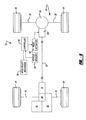
- Drivetrain 10 for a four-wheel drive vehicle is shown.
- Drivetrain 10 includes a primary driveline 12, a secondary driveline 14, and a powertrain 16 for delivering rotary tractive power (i.e., drive torque) to the drivelines.
- primary driveline 12 is the rear driveline while secondary driveline 14 is the front driveline.
- Powertrain 16 includes an engine 18, a multi-speed transmission 20, and a power transmission device hereinafter referred to as transfer case 22.
- Rear driveline 12 includes a pair of rear wheels 24 connected at opposite ends of a rear axle assembly 26 having a rear differential 28 coupled to one end of a rear prop shaft 30, the opposite end of which is coupled to a rear output shaft 32 of transfer case 22.
- front driveline 14 includes a pair of front wheels 34 connected at opposite ends of a front axle assembly 36 having a front differential 38 coupled to one end of a front prop shaft 40, the opposite end of which is coupled to a front prop shaft 42 of transfer case 22.
- drivetrain 10 is shown to further include an electronically-controlled power transfer system for permitting a vehicle operator to select between a two-wheel drive mode, a locked ("part-time”) four-wheel drive mode, and an adaptive (“on-demand”) four-wheel drive mode.
- transfer case 22 is equipped with a transfer clutch 50 that can be selectively actuated for transferring drive torque from rear output shaft 32 to front output shaft 42 for establishing both of the part-time and on-demand four-wheel drive modes.
- the power transfer system further includes a power-operated mode actuator 52 for actuating transfer clutch 50, vehicle sensors 54 for detecting certain dynamic and operational characteristics of the motor vehicle, a mode select mechanism 56 for permitting the vehicle operator to select one of the available drive modes, and a controller 58 for controlling actuation of mode actuator 52 in response to input signals from vehicle sensors 54 and mode selector 56.
- a power-operated mode actuator 52 for actuating transfer clutch 50
- vehicle sensors 54 for detecting certain dynamic and operational characteristics of the motor vehicle
- mode select mechanism 56 for permitting the vehicle operator to select one of the available drive modes
- controller 58 for controlling actuation of mode actuator 52 in response to input signals from vehicle sensors 54 and mode selector 56.
- Transfer case 22 is shown in FIG. 2 to include a multipiece housing 60 from which rear output shaft 32 is rotatably supported by a pair of laterally-spaced bearing assemblies 62.
- Rear output shaft 32 includes an internally-splined first end segment 64 adapted for connection to the output shaft of transmission 20 and a yoke assembly 66 secured to its second end segment 68 that is adapted for connection to rear propshaft 30.
- Front output shaft 42 is likewise rotatably supported from housing 60 by a pair of laterally-spaced bearing assemblies 70 and 72 and includes an internally-splined end segment 74 that is adapted for connection to front propshaft 40.
- Transfer clutch 50 is a multi-plate friction clutch assembly 80 and mode actuator 52 is a power-operated clutch actuator assembly 82 which together define a torque transfer mechanism according to a preferred embodiment of the present invention.
- Friction clutch assembly 80 includes a hub 84 fixed via a spline connection 86 to rear output shaft 32, a drum 88, and a multi-plate clutch pack 90 that is operably disposed between hub 84 and drum 88.
- Clutch pack 90 includes a set of outer clutch plates 92 splined for rotation with drum 88 and which are interleaved with a set of inner clutch plates 94 splined for rotation with hub 84.
- Clutch assembly 80 further includes a pressure plate 96 that is splined for rotation with drum 88 and which has an annular rim flange 98 formed thereon.
- Pressure plate 96 is operably arranged to rotate with, and move axially relative to, drum 88 for exerting a compressive clutch engagement force on clutch pack 90.
- Such engagement of clutch pack 90 causes rotary power ("drive torque") to be transferred from rear output shaft 32 to front output shaft 42 via a transfer assembly 100.
- Transfer assembly 100 includes a first sprocket 102 fixed via a spline connection 104 for rotation with drum 88, a second sprocket 106 fixed for rotation with front output shaft 42, and a power chain 108 encircling sprockets 102 and 106.
- First sprocket 102 is shown fixed to a tubular stub shaft segment 89 of drum 88 which is rotatably supported on rear output shaft 32 via a suitable bearing assembly such as sleeve bushing
- clutch actuator assembly 82 is operable for controlling axial movement of pressure plate 96 and thus, the magnitude of the clutch engagement force applied to clutch pack 90.
- pressure plate 96 is axially moveable relative to clutch pack 90 between a first or “released” position and a second or “locked” position. With pressure plate 96 in its released position, a minimum clutch engagement force is exerted on clutch pack 90 such that virtually no drive torque is transferred from rear output shaft 32 through clutch assembly 80 and transfer assembly 100 to front output shaft 42, thereby establishing the two-wheel drive mode.
- clutch actuator assembly 82 is shown to generally include an electric motor/brake unit 110, a torque/force conversion mechanism 112, and force amplification mechanism 114.
- Motor/brake unit 110 is an annular assembly which includes a stator 116 and a rotor 120.
- Stator 116 is shown to be non-rotationally secured to housing 60 and includes sets of windings, referred to as coil 118, which has its electrical lead wires 122 extending out of housing 60 via a sealed plug hole 124.
- Rotor 120 includes a plate seqment 126 and an annular rim segment 128. As will be detailed, plate segment 126 of rotor 120 is fixed for rotation with a first component of torque/force conversion mechanism 112.
- rim segment 128 of rotor 120 has a plurality of permanent magnets 130 secured thereto which are arranged in close proximity to the field windings of coil 118.
- the annular configuration of motor/brake unit 110 permits simple assembly in concentric relation to rear output shaft 32 within housing 60.
- the packaging of motor/brake unit 110 inside housing 60 is advantageous in comparison to externally-mounted electric motor-type clutch actuators that are exposed to the hostile road and weather conditions associated with power transmission devices in motor vehicles.
- Torque/force conversion mechanism 112 is shown in FIGS. 2 and 3 as a ball screw operator 132 having an externally-threaded screw 134, an internally-threaded nut 136, and balls 138 disposed in the aligned threads therebetween.
- Screw 134 is rotatably supported on rear output shaft 32 via a pair of needle bearing assemblies 140.
- Screw 134 is located and axially restrained between hub 84 and a thrust bearing assembly 142 via a snap ring 144.
- plate segment 126 of rotor 120 is fixed (i.e., welded, splined, etc.) for rotation with screw 134.
- Ball screw operator 132 is operable to cause axial movement of nut 136 relative to screw 134 in response to relative rotation therebetween.
- the torque outputted from motor/brake unit 110 is converted into an axially-directed thrust force.
- This axially-directed thrust force is amplified and subsequently transferred to pressure plate 96 via force amplification mechanism 114.
- force amplification mechanism 114 it may be possible to eliminate force amplification mechanism 114 and apply the thrust force outputted from ball screw operator 132 to pressure plate 96.
- Force amplification mechanism 114 is shown to include a disk-type spring plate, such as a belleville spring 148, having a first end restrained against an annular retainer 150 fixed to nut 136 and a second end restrained in a circumferential groove 152 formed in drum 88.
- belleville spring 148 has lugs at its outer peripheral edge that are coupled to drum 88 and lugs at its inner peripheral edge that are coupled to retainer 150.
- belleville spring 148 couples nut 136 of ball screw operator 132 for common rotation with drum 88. In operation, when no torque is applied to rotor 120, screw 134 and nut 136 rotate together in response to rotation of drum 88.
- belleville spring 148 acts as a lever arm with an intermediate portion engaging rim flange 98 on pressure plate 96.
- a resilient ring 154 is retained in groove 152 between the outer end of belleville spring 148 and a reaction flange 156 that extends from drum 88.
- forward travel (i.e., to the left in FIG. 3) of nut 136 causes spring 148 to amplify the magnitude of the longitudinally-directed thrust force generated by ball screw operator 132 and apply the resultant clutch engagement force on pressure plate 96.
- the use of ball screw operator 132 in combination with disk spring 148 permits use of a low torque motor/brake unit 110.
- motor/brake unit 110 will be controlled in either of a first ("motor”) mode or a second (“brake”) mode for controlling the torque applied to rotor 120 so as to control relative rotation between screw 134 and nut 136, thereby controlling the magnitude of the clutch engagement force applied by pressure plate 96 on clutch pack 90.
- clutch actuator assembly 82 requires only minimal electric power from the vehicle's host electrical supply system since, throughout most of its typical duty cycle, motor/brake unit 110 functions in its brake mode and acts as an absorber/generator for generating electrical power that can be dissipated or used to power one or more auxiliary electric devices such as, for example, an electric lube pump.
- motor/brake unit 110 when the rotary speed of rear output shaft 32 is below a predefined threshold value, motor/brake unit 110 operates in its motor mode wherein coil 118 must be energized via an electrical control signal from controller 58 to drive rotor 120 in the appropriate rotary direction and through a desired amount of angular travel.
- Such controlled rotation of rotor 120 causes nut 136 of ball screw operator 132 to move axially relative to screw 134 in a corresponding direction and through a desired length of travel, thereby varying the magnitude of the clutch engagement force applied to clutch pack 90.
- the predefined threshold rotary speed value is preferably, but not limited to, about 150 rpm which equates to a vehicle rolling speed of about 5 mph.
- the torque transfer mechanism of the present invention only uses motor/brake unit 110 in its motor mode to control torque transfer requirements during low speed situations.
- motor/brake unit 110 operates in its motor mode to control the transfer of drive torque to front output shaft 42 during a quick start or acceleration situation to avoid traction loss of rear wheels 24.
- the control system switches functions such that motor/brake unit 110 operates in its brake mode as an electric brake (absorber/generator) for creating (regenerating) electric power.
- motor/brake unit 110 operates in its brake mode as an electric brake (absorber/generator) for creating (regenerating) electric power.
- rotation of rotor 120 causes magnets 130 to generate a voltage in the field windings of coil 118.
- coil 118 is not energized, no torque is applied to rotor 120.
- ball screw operator 132 continues to rotate as a unit and nut 136 does not move axially in either direction.
- motor/brake unit 110 Upon energization of coil 118, a brake torque is generated which acts to slow rotation of rotor 120 and thus slow rotation of screw 134 relative to nut 136, thereby causing axial travel of nut 136 relative to clutch pack 90.
- the control system functions to maintain a predetermined torque on ball screw operator 132 which, in turn, acts to control engagement of clutch pack 90 so as to generate the desired amount of torque transfer to front output shaft 42.
- motor/brake unit 110 is a dc pemanetic magnetic device since it will not require a commutator or brushes.
- controller 58 signals electric motor/brake unit 110 to rotate screw 134 until nut 136 is located in a rearward or "retracted” position. Such action permits pressure plate 96 to move to its released position. If mode selector 56 thereafter indicates selection of the part-time four-wheel drive mode, coil 118 of electric motor/brake unit 110 is signaled by controller 58 to rotate screw 134 for axially advancing nut 136 until it is located in a forward or "extended” position. Such movement of nut 136 to its extended position acts to cause corresponding movement of pressure plate 96 to its locked position, thereby coupling front output shaft 42 to rear output shaft 32 through clutch assembly 80 and transfer assembly 100.
- controller 58 When mode selector 56 indicates selection of the on-demand four-wheel drive mode, controller 58 signals motor/brake unit 110 to rotate screw 134 until nut 136 is located in a "stand-by" position. This stand-by position may be its retracted position or, in the alternative, an intermediate position. In either case, a predetermined minimum amount of drive torque is delivered to front output shaft 42 through clutch assembly 80 which is considered to be in its "ready” condition. Thereafter, controller 58 determines when and how much drive torque needs to be transferred to front output shaft 42 based on the current tractive conditions and/or operating characteristics of the motor vehicle, as detected by sensors 54. Many control schemes are known in the art for determining a desired torque level to be transferred through a transfer clutch and adaptively controlling such actuation of the transfer clutch. In this regard, commonly owned U. S. Patent No. 5,323,871 discloses a non-limiting example of a clutch control scheme and the various sensors used therewith, the entire disclosure of which is incorporated by reference.
- a modified version of transfer case 22 is identified by reference numeral 22A which includes a multi-plate clutch assembly 180 and a power-operated clutch actuator assembly 182 which together define a torque transfer mechanism according to another preferred embodiment of the present invention.
- Clutch assembly 180 includes a hub 184 fixed via a spline connection 186 to first sprocket 102, a drum 188 fixed via a spline connection 189 to rear output shaft 32, and a multi-plate clutch pack 190.
- Clutch pack 190 includes a set of outer clutch plates 192 splined for rotation with drum 188 which are alternatively interleaved with a set of inner clutch plates 194 that are splined for rotation with hub 184.
- Clutch assembly 180 further includes a pressure plate 196 that is splined for rotation with drum 188 and having an annular rim flange 198 formed thereon.
- a reaction plate 200 is splined to drum 188 and axially restrained thereon via a snap ring 202.
- clutch actuator assembly 182 is generally shown to include an electric motor/brake unit 210, a torque/force conversion mechanism 212, and a force amplification mechanism 214.
- Motor/brake unit 210 includes an annular stator 216 that is secured to housing 60 and has a coil 218, and a rotor 220 having a plurality of permanent magnets 230 secured thereto in close proximity to coil 218.
- Torque/force conversion mechanism 212 is a ball screw operator 232 having an internally-threaded nut 234, an externally threaded screw 236, and balls 238 disposed in the aligned threads therebetween.
- Screw 236 is supported on an annular hub segment 240 of drum 188.
- a drive plate 242 is secured to one end of screw 236 and has a series of circumferentially aligned axially-extending pins 244. Pins 244 pass through a series of commonly aligned throughbores 246 formed in a plate segment 248 of drum 188.
- Nut 234 is shown to be formed integrally with rotor 220 and axially restrained between a pair of thrust washer assemblies 250.
- thrust washer assemblies 250 is disposed between a first end of screw 236 and a support plate 252 that is rotatably supported from housing via a bearing assembly 254.
- the other thrust washer assembly 250 is disposed between a second end of nut 234 and a cup-shaped retainer 256 that is secured to plate segment 248 of drum 188. Since drum 188 is driven by rear output shaft 32, the location of pins 244 within throughbores 246 causes screw 236 to likewise rotate in common with rear output shaft 32. As before, when no energy is applied/absorbed to drive/brake rotation of rotor 220, nut 234 rotates in unison with screw 236.
- Ball screw operator 232 is operable to cause axial movement of screw 236 relative to nut 234 between its retracted and extended positions in response to relative rotation therebetween.
- the axially-directed thrust force generated by such axial movement of screw 234 is transferred from pins 244 to pressure plate 196 via force amplification mechanism 214.
- Force amplification mechanism 214 includes a series of disk levers 260 and having an outer end fixed via a spline connection to drum 188 and an inner end in engagement with the free end of pins 244.
- Levers 260 each have an intermediate portion engaging rim flange 198 on pressure plate 196.
- a return spring assembly 262 is disposed between hub 184 and disk levers 260 and includes a spring retainer 264 and a plurality of wave springs 266 disposed between a flange on spring retainer 264 and the inner end of disk levers 260 opposite pins 244.
- retainer 264 is located on rear output shaft 32 between an end of hub segment 268 of sprocket 102 by a thrust washer 270 and snap ring 272.
- Wave springs 266 are provided to bias disk levers 260 to a released position which, in turn, functions to bias screw 234 toward its retracted position.
- motor/brake unit 210 The function and operation of motor/brake unit 210 is generally similar to that of motor/brake unit 110 in that energization of coil 218 in either of the motor or brake modes controls axial travel of screw 236 relative to nut 234.
- Screw 236 is moveable between retracted and extended positions relative to nut 234 for causing pins 244 to pivot levers 260 so as to move pressure plate 196 between its corresponding released and locked positions.
- screw 236 is shown in the upper-half of FIG. 4 in its retracted position and in the lower-half thereof in its extended position.
- Spring assembly 262 is arranged to normally bias screw 236 toward its retracted position. Again, only minimal electric power is required to precisely control engagement of clutch assembly 180 and thus, the drive torque transferred from rear output shaft 32 to front output shaft 42.
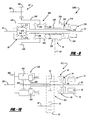
- FIG. 5 schematically depicts a front-wheel based four-wheel drivetrain layout 10' for a motor vehicle.
- engine 18 drives a multi-speed transmission 20' having an integrated front differential unit 38' for driving front wheels 34 via axle shafts 33.
- a transfer unit 35 is also driven by transmission 20' for delivering drive torque to the input member of a torque transfer mechanism, such as an in-line torque coupling 280, via a drive shaft 30'.
- the input member of torque coupling 280 is coupled to drive shaft 30' while its output member is coupled to a drive component of rear differential 28 which, in turn, drives rear wheels 24 via axleshafts 25.
- controller 58 adaptively controls actuation of torque coupling 280 such that drive torque is delivered "on-demand" to rear wheels 24.
- torque transfer coupling 280 would include a multi-plate clutch assembly and a clutch actuator assembly that are similar in structure and function to either of the torque transfer mechanisms previously described herein.
- torque coupling 280 is schematically illustrated operably disposed between drive shaft 30' and rear differential 28.
- Rear differential 28 includes a pair of side gears 282 that are connected to rear wheels 24 via rear axle shafts 25.
- Differential 28 also includes pinions 284 that are rotatably supported on pinion shafts fixed to a carrier 286 and which mesh with side gears 282.
- a right-angled drive mechanism is associated with differential 28 and includes a ring gear 288 that is fixed for rotation with carrier 286 and meshed with a pinion gear 290 that is fixed for rotation with a pinion shaft 292.
- Torque coupling 280 includes a mutli-plate clutch assembly 294 operably disposed between driveshaft 30' and pinion shaft 292 and which includes a hub 296 fixed for rotation with driveshaft 30', a drum 298 fixed for rotation with pinion shaft 282, and a clutch pack 300.
- Torque coupling 280 also includes a clutch actuator assembly 302 for controlling the magnitude of the clutch engagement force applied to clutch assembly 294 and thus the amount of drive torque transferred from drive shaft 30' to rear differential 28.
- clutch actuator assembly 302 is contemplated to be similar to either of clutch actuator assemblies 82,182 in that an electric motor/brake unit controls translation of a ball screw operator which, in turn, controls engagement of the clutch pack 300.
- Torque coupling 280 permits operation in any of the drive modes previously disclosed. For example, if the on-demand 4WD mode is selected, controller 58 regulates activation of clutch actuator 302 in response to the operating conditions detected by sensors 54 by controllably varying the electric control signal sent to the motor/brake unit. Selection of the part-time 4WD mode results in complete engagement of clutch pack 300 such that pinion shaft 292 is, in effect, rigidly coupled to driveshaft 30'. Finally, in the two-wheel drive mode, clutch pack 300 is released such that pinion shaft 292 is free to rotate relative to driveshaft 30'. Alternatively, elimination of mode select mechanism 56 would provide automatic on-demand operation of torque coupling 280 in a manner completely transparent to the vehicle operator.
- torque coupling 280A is schematically illustrated in association with a power transmission device adapted for use with an on-demand four-wheel drive system based on a front-wheel drive vehicle similar to that shown in FIG. 5.
- torque coupling 280 is shown operably associated with transfer unit 35 for transferring drive torque from transaxle 20' to drive shaft 30'.
- an output shaft 303 of transaxle 20' is shown to drive an output gear 304 which, in turn, drives an input gear 306 that is fixed to a carrier 308 associated with front differential unit 38'.
- front differential unit 38' includes a pair of side gears 310 that are connected to front wheels 34 via axleshafts 33.
- Differential unit 38' also includes a pair of pinions 312 that are rotatably supported on pinion shafts fixed to carrier 308 and which are meshed with side gears 310.
- a transfer shaft 314 is provided to transfer drive torque from carrier 308 to a clutch hub 316 associated with a multi-pate clutch assembly 318.
- Clutch assembly 318 further includes a drum 320 and a clutch pack 322 having interleaved inner and outer clutch plates respectively connected between hub 316 and drum 320.
- Transfer unit 35 is a right-angled drive mechanism including a ring gear 324 fixed for rotation with drum 320 of clutch assembly 318 and which is meshed with a pinion gear 326 fixed for rotation with drive shaft 30.
- a clutch actuator assembly 328 is schematically illustrated for controlling actuation of clutch assembly 318.
- clutch actuator assembly 328 is similar to one of clutch actuator assemblies 82,182 previously described in that an electric motor/brake unit controls translational movement of a ball screw operator which, in turn, controls engagement of clutch pack 322.
- drive torque is transferred from the primary (i.e., front) driveline to the secondary (i.e., rear) driveline in accordance with the particular mode selected by the vehicle operator via mode selector 56.
- controller 58 regulates actuation of clutch actuator 328 in response to the vehicle operating conditions detected by sensors 54 by varying the electric signal sent to the electric motor/brake unit.
- the level of clutch engagement and the amount of drive torque that is transferred through clutch pack 322 to the rear driveline through transfer unit 35 and drive shaft 30 is adaptively controlled.
- Selection of a locked or part-time 4WD mode results in full engagement of clutch assembly 318 for rigidly coupling the front driveline to the rear driveline.
- the mode selector 56 may be eliminated such that only the on-demand 4WD mode is available so as to continuously provide adaptive traction control without input from the vehicle operator.
- FIG. 8 illustrates a modified version of FIG. 7 wherein an on-demand four-wheel drive system is shown based on a rear-wheel drive motor vehicle that is arranged to normally deliver drive torque to rear wheels 24 while selectively transmitting drive torque to front wheels 34 through a torque coupling 280B.
- drive torque is transmitted directly from transmission output shaft 303 to transfer unit 35 via an intermediate shaft 330 interconnecting input gear 306 to ring gear 324. Since ring gear 324 is driven by the output of transaxle 20', transfer unit 35 supplies drive torque to rear axle assembly 26 via driveshaft 30.
- torque coupling 280B is shown operably disposed between intermediate shaft 330 and transfer shaft 314.
- clutch assembly 318 is arranged such that drum 320 is driven with ring gear 324 by intermediate shaft 330.
- actuation of clutch actuator 328 functions to transfer drive torque from drum 320 through clutch pack 322 to hub 316 which, in turn, drives carrier 308 of front differential unit 38' via transfer shaft 314.
- the vehicle could be equipped with mode selector 56 to permit selection by the vehicle operator of either the adaptively controlled on-demand 4WD mode or the locked part-time 4WD mode.
- the on-demand 4WD mode is the only drive mode available and provides continuous adaptive traction control without input from the vehicle operator.
- FIG. 9 schematically illustrates a full-time four-wheel drive system which is generally similar to the on-demand four-wheel drive system shown in FIG. 8 with the exception that an interaxle differential unit 340 is now operably installed between front differential unit 38' and transfer unit 35.
- output gear 306 is fixed for rotation with a carrier 342 of interaxle differential 340 from which pinion gears 344 are rotatably supported.
- a first side gear 346 is meshed with pinion gears 344 and is fixed for rotation with intermediate shaft 330 so as to be drivingly interconnected to the rear driveline through transfer unit 35.
- a second side gear 348 is meshed with pinion gears 344 and is fixed for rotation with transfer shaft 314 and carrier 308 of front differential unit 38' so as to be drivingly interconnected to the front driveline.
- torque bias coupling 280C A torque transfer mechanism, referred to as torque bias coupling 280C, is shown to be operably disposed between side gears 346 and 348.
- Torque bias coupling 280C is similar to torque transfer coupling 280B except that it is now operably arranged between the driven outputs of interaxle differential 340 for providing a torque biasing and slip limiting function.
- Torque bias coupling 280C is shown to include multi-plate clutch assembly 318 and clutch actuator 328.
- Clutch assembly 318 is operably arranged between transfer shaft 314 and intermediate shaft 330.
- controller 58 controls the electric motor/brake unit associated with clutch actuator 328 for controlling engagement of clutch assembly 318 and thus the torque biasing between the front and rear driveline.
- a full-time 4WD system is shown to include a transfer case 22C equipped with an interaxle differential 350 between an input shaft 351and output shafts 32' and 42'.
- Differential 350 includes a rotary input member defined as a planet carrier 352, a first rotary output member defined as a first sun gear 354, a second rotary output member defined as a second sun gear 356, and a gearset for accommodating speed differentiation between first and second sun gears 354 and 356.
- the gearset includes meshed pairs of first planet gears 358 and second pinions 360 which are rotatably supported by carrier 352.
- First planet gears 358 are shown to mesh with first sun gear 354 while second planet gears 350 are meshed with second sun gear 356.
- First sun gear 354 is fixed for rotation with rear output shaft 32' so as to transmit drive torque to rear driveline 12.
- second sun gear 356 is coupled to transfer assembly 100 which includes a first sprocket 78 rotatably supported on rear output shaft 32', a second sprocket 82 fixed to front output shaft 42', and a power chain 84.
- Transfer case 22C further includes a torque biasing clutch 50 having a multi-plate clutch assembly 86 and a mode actuator 52 having a clutch actuator assembly 88.
- Clutch assembly 86 includes a drum 94 fixed for rotation with first sprocket 78, a hub 90 fixed for rotation with rear output shaft 32', and a multi-plate clutch pack 98 operably disposed therebetween.
- Clutch actuator assembly 88 is structurally and functionally similar to the clutch actuators previously described. If a mode select mechanism is available, transfer case 22C would permit operation in either of an adaptive full-time four-wheel drive mode or a locked four-wheel drive mode.
- a drive axle assembly 370 which is generally a modified version of rear axle assembly 26 and which incorporates a torque transfer mechanism in association with rear differential 28 so as to permit adaptive control of the torque biasing and intra-axle speed differentiation between rear wheels 24.
- the torque transfer mechanism is a torque bias coupling 368 shown to include a multi-plate clutch assembly 372 that is operably disposed between carrier 286 and one of axleshafts 25, and a clutch actuator assembly 374.
- Clutch assembly 372 includes a drum 376 fixed for rotation with carrier 286, a hub 378 fixed for rotation with one of axleshafts 25, and a clutch pack 380 disposed therebetween.
- Clutch actuator assembly 374 is operable for controlling the magnitude of a clutch engagement force applied to clutch pack 380 and thus, the torque biasing between the left and right wheels 24.
- Clutch actuator assembly 374 is similar to clutch actuators 82,182 and includes a motor/brake unit, a torque/force conversion mechanism and a force amplification mechanism.
- Drive axle assembly 370 can be used alone or in combination with other torque transfer mechanisms disclosed herein.
- drive axle assembly 370 can be associated with the primary axle in a rear wheel based on-demand 4WD drivetrain (FIGS. 1 and 8), a front wheel based on-demand 4WD drivetrain (FIGS. 5 and 7) or in either (or both) axles in full-time 4WD drivetrains (FIGS. 9 and 10).
- FIG. 12 is a schematic illustration of drivetrain 10 from FIG. 1 with drive axle assembly 370 used in substitution for rear axle assembly 26. Electric power to clutch actuator assembly 82 of the torque transfer coupling in transfer case 22 is shown by power line 390 while regenerated electric power from clutch actuator assembly 82 is shown by dashed line 392.
- FIG. 13 a block diagram is provided to better illustrate the electric power system associated with the drivetrain shown in FIG. 12.
- Block 400 indicates the drive torque supplied to transfer case 22 by engine 18 and transmission 20 while block 402 indicates the electric power delivered to controller 58 from the vehicle's host system.
- a unique aspect of the present invention is that power from the vehicle's host system is only required during operation of the motor/brake unit in the motor mode to drive the rotor and in the brake mode to energize the coil windings.
- the electric power regenerated during operation of one clutch actuator in its brake mode can be used by controller 58 to provide electric power the other clutch actuator.
- FIGS. 12 and 13 illustrate concurrent use and control of two distinct motor/brake units which are only minimally reliant on electric power from the vehicle's host electric system.
- a similar dual coupling arrangement using drive axle assembly 370 can be provided in association with the rear wheel based power transmission device shown in FIG. 8.
- FIG. 14 is a modified version of the front wheel based power transmission device shown in FIG. 7 which now further incorporates torque bias coupling 368 in association with front differential 38'.
- torque drive coupling 368 provides adaptive control of intra-axle differentiation between front wheels 34 while torque coupling 280A provides adaptive control of the drive torque transferred on-demand to the rear driveline.
- the power sharing arrangement shown in FIG. 13 would again be applicable for controlling the dual coupling powertrain of FIG. 14.
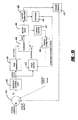
- control system for controlling operation of the motor/brake unit(s) will now be detailed.
- the control system and its associated algorithms, is employed to control a brushless dc motor-based clutch actuator assembly.
- the actuator assembly permits modulated control of the torque outputted from its associated clutch assembly.
- the control system can receive a torque output command from a powertrain control module via a communications link. This command is translated into an electric current level for the brushless motor by the algorithms.
- a desired current level is maintained in the motor by a feedback control loop, either by sensing the actual motor current or by sensing the actual torque outputted by the clutch assembly.
- Commutation of the brushless motor drive is also performed by the controller.
- the motor position is relayed to the controller by the output state of three hall effect sensors embedded in the coil windings.
- the controller energizes the correct winding pair based on the output from the hall sensors and the desired direction of rotor rotation.
- the torque command from controller 58 is delivered to a summing function 410 where the torque command value is compared to the actual torque output value measured by a torque sensor 412 on the output of the clutch assembly.
- a discrete control law function 418 has as its input the torque error (e T ) value outputted from summing function 410.
- Discrete control law function 418 transforms the torque error (e T ) into a signal that command the subsequent functions to compensate for the error.
- the output signal of control law function 418 commands the magnitude and sign of the clutch engagement force.
- a PWM (pulse width modulation) generator 420 receives the output signal from discrete control law function 418 and outputs a directly proportional duty cycle pulse train that controls the magnitude of the electric current sent to the coil of motor/brake unit.
- a field switch 422 outputs binary signals that control the direction of rotation of the rotor of the motor/brake unit. These direction signals are dictated by the sign of the output signal from control law function 418. Hence, if the current vector is negative, the motor will turn one way, and if the current vector is positive, the motor will turn in the opposite direction. One direction of rotation acts to increase output torque, while the other reduces pressure on the clutch and thereby reduces the output torque.
- An H-bridge circuit 424 is configured from four controlled switches (i.e., relay, transistor) that allows control of both the direction and magnitude of electric current through a load (i.e., motor). Two of the four switches are activated to direct current in a given direction. In addition, one of the two remaining devices is modulated so as to control the amount (magnitude) of current.
- switches i.e., relay, transistor
- Motor field block 426 represents the coils and pole pieces of the windings associated with motor/brake units' field.
- Motor armature 428 is the rotating member of the motor (i.e., the rotor) that also carries the magnet pole pairs.
- An encoder 430 is a sensor that outputs a signal which identifies the position of the motor armature with respect to the field coils, as well as the speed and direction of motor rotation. This block is necessary for realizations where the motor is electrically commutated (i.e., brushless motors).
- torque sensor 412 outputs an electrical signal that is proportional to the torque applied to the device to which the sensor is attached.
- a current sensor 432 outputs an electrical signal that is proportional to the electrical current acting thereon.
- a torque estimator 434 can be employed to estimate the clutch output torque. It does so by operating mathematically on the current sensor's signal to provided an estimate of the output torque. In practice, this may be a simple linear relationship or a more complex function.
Abstract
Description
- FIG. 1
- illustrates the drivetrain of a four-wheel drive vehicle equipped with the power transmission device of the present invention;
- FIG. 2
- is a sectional view of a transfer case associated with the drivetrain shown in FIG. 1 and which is equipped with a torque transfer mechanism according to a first embodiment of the present invention;
- FIG. 3
- is an enlarged partial view taken from FIG. 2 showing components of the torque transfer mechanism is greater detail;
- FIG. 4
- is a partial sectional view of the transfer case equipped with a torque transfer mechanism according to a second embodiment of the present invention;
- FIG. 5
- is a schematic illustration of an alternative driveline for a four-wheel drive motor vehicle equipped with a power transmission device of the present invention;
- FIG. 6
- is a schematic illustration of an in-line coupling associated with the drivetrain shown in FIG. 5 and equipped with a torque transfer mechanism according to the present invention;
- FIGS. 7 and 8
- schematically illustrate power transmission devices for use in on-demand four-wheel drive vehicles equipped with a torque transfer mechanism according to the present invention;
- FIG. 9
- shows a power transmission device for use in a full-time four-wheel drive vehicle which is equipped with a torque transfer mechanism according to the present invention;
- FIG. 10
- illustrates a transfer case for use in a full-time four-wheel drive vehicle equipped with a torque transfer mechanism according to the present invention;
- FIG. 11
- shows a drive axle assembly equipped with a torque transfer mechanism of the present invention;
- FIG. 12
- is a schematic illustration of a drivetrain for a four-wheel drive vehicle incorporating two torque transfer mechanisms;
- FIG. 13
- is a block diagram of an electric power control system for the four-wheel drive vehicle shown in FIG. 12;
- FIG. 14
- is a schematic illustration of a drivetrain for a four-wheel drive vehicle according to the present invention; and
- FIG. 15
- is a block diagram of a control system for adaptive control of the torque transfer mechanisms of the present invention.
Claims (16)
- A power transmission device, comprising:a first rotary member;a second rotary member;a torque transfer mechanism for transferring drive torque from said first rotary member to said second rotary member, said torque transfer mechanism including a friction clutch assembly operably disposed between said first and second rotary members and a clutch actuator assembly for applying a clutch engagement force on said friction clutch assembly, said clutch actuator assembly including an electric motor having a rotor, and a torque/force conversion mechanism rotatively driven by one of said first and second rotary members and having a first component fixed for rotation with said rotor and a second component supported for movement between a first position and a second position in response to relative rotation between said first and second components, said second component operable to exert a minimum clutch engagement force on said friction clutch assembly when located in its first position and a maximum clutch engagement force when located in its second position, said motor being operable in a motor mode wherein said rotor is driven to cause relative rotation between said first and second components and a in brake mode wherein said rotor is braked to cause such relative rotation; anda controller for switching said electric motor from said motor mode into said brake mode when the rotary speed of one of said first and second rotary members exceeds a predetermined rotary speed value.
- The power transmission device of Claim 1 wherein said controller provides electrical power to drive said rotor when said motor is operating in its motor mode, and wherein electrical power generated by rotation of said rotor is used to brake said rotor when said motor is operating in its brake mode.
- The power transmission device of Claim 3 wherein said friction clutch assembly includes a hub fixed for rotation with one of said first and second rotary members, a drum fixed for rotation with the other of said first and second rotary members, and a clutch pack operably disposed between said hub and drum, and wherein said torque/conversion mechanism is a ball screw operator, said first component of said ball screw operator is a screw and said second component is a nut, said rotor of said motor being fixed for rotation with said screw such that actuation of said motor causes said screw to rotate relative to said nut whereby said nut moves relative to said clutch pack between its first and second positions.
- The power transmission device of Claim 3 further comprising a force amplification mechanism interconnected between said drum and said nut and operable for increasing the thrust force generated by movement of said nut so as to increase the magnitude of the clutch engagement force exerted on said clutch pack.
- The power transmission device of Claim 3 wherein said nut is caused to move linearly between its first retracted position and its second extended position in response to the direction and magnitude of rotary movement of said screw and said rotor caused by actuation of said motor.
- The power transmission device of Claim 1 wherein said motor includes a coil and said rotor includes magnets located in close proximity to said coil, rotation of said rotor with said ball screw operator cause said magnets to induce a magnetic field in said coil such that energization of said coil causes said rotor to be braked when said motor is operating in its brake mode.
- The power transmission device of Claim 1 wherein said friction clutch assembly includes a hub fixed for rotation with one of said first and second rotary members, a drum fixed for rotation with the other of said first and second rotary members, and a clutch pack operably disposed between said hub and drum, and wherein said torque/conversion mechanism is a ball screw operator, said first component of said ball screw operator is a nut and said second component is a screw, said rotor of said motor being fixed for rotation with said nut such that actuation of said motor causes said nut to rotate relative to said screw, whereby said screw moves relative to said clutch pack.
- The power transmission device of Claim 7 further comprising a force amplification mechanism interconnected between said drum and said screw and operable for increasing the thrust force generated by movement of said screw so as to increase the magnitude of the clutch engagement force exerted on said clutch pack.
- The power transmission device of Claim 7 wherein said screw is caused to move linearly between its first retracted position and its second extended position in response to the direction and magnitude of rotary movement of said nut and said rotor caused by actuation of said motor.
- The power transmission device of Claim 1 wherein said first rotary member is a first shaft driving a first driveline of a motor vehicle, said second rotary member is a second shaft coupled to a second driveline of the motor vehicle, and wherein said torque transfer mechanism is operable to transfer drive torque from said first shaft to said second shaft.
- The power transmission device of Claim 10 defining a transfer case wherein said first shaft is a primary output shaft driving the primary driveline, said second shaft is a secondary output shaft coupled to the secondary driveline, and wherein location of said second component in its first position releases engagement of said clutch assembly so as to define a two-wheel drive mode, and location of said second component in its second position fully engages said clutch assembly so as to define a part-time four-wheel drive mode, said controller is operable to control said electric motor for varying the position of said second component between its first and second positions to controllably vary the drive torque transferred from said primary output shaft to said secondary output shaft so as to define an on-demand four-wheel drive mode.
- The power transmission device of Claim 10 defining a power take-off unit wherein said first shaft provides drive torque to a first differential associated with the first driveline, and wherein said second shaft is coupled to a second differential associated with the second driveline.
- The power transmission device of Claim 1 wherein said first rotary member is a drive shaft driven by a drivetrain of a motor vehicle, said second rotary member is a pinion shaft driving a differential associated with an axle assembly of the motor vehicle, and wherein said friction clutch assembly is disposed between said drive shaft and said pinion shaft such that actuation of said clutch actuator assembly is operable to transfer drive torque from said drive shaft to said pinion shaft.
- The power transmission device of Claim 1 wherein said first rotary member includes a first differential supplying drive torque to a pair of first wheels in a motor vehicle, and a transfer shaft driven by said first differential, said second member includes a drive shaft coupled to a second differential interconnecting a pair of second wheels in the motor vehicle, and wherein said friction clutch assembly is disposed between said transfer shaft and said drive shaft.
- The power transmission device of Claim 1 wherein said first rotary member includes a first shaft supplying drive torque to a second shaft which is coupled to a first differential for driving a pair of first wheels in a motor vehicle, said second rotary member is a third shaft driving a second differential interconnecting a pair of second wheels of the motor vehicle, and wherein said friction clutch assembly is operably disposed between said first and third shafts.
- The power transmission device of Claim 1 further including an interaxle differential driven by said first rotary member and having a first output driving a first driveline in a motor vehicle and a second output driving a second driveline in the motor vehicle, and wherein said friction clutch assembly is operably disposed between said first and second outputs of said interaxle differential.
Applications Claiming Priority (2)
| Application Number | Priority Date | Filing Date | Title |
|---|---|---|---|
| US371415 | 2003-02-21 | ||
| US10/371,415 US6808053B2 (en) | 2003-02-21 | 2003-02-21 | Torque transfer device having an electric motor/brake actuator and friction clutch |
Publications (3)
| Publication Number | Publication Date |
|---|---|
| EP1449704A2 true EP1449704A2 (en) | 2004-08-25 |
| EP1449704A3 EP1449704A3 (en) | 2005-08-24 |
| EP1449704B1 EP1449704B1 (en) | 2010-03-31 |
Family
ID=32736458
Family Applications (1)
| Application Number | Title | Priority Date | Filing Date |
|---|---|---|---|
| EP04003372A Expired - Fee Related EP1449704B1 (en) | 2003-02-21 | 2004-02-13 | Torque transfer device having an electric motor/brake actuator and friction clutch |
Country Status (4)
| Country | Link |
|---|---|
| US (3) | US6808053B2 (en) |
| EP (1) | EP1449704B1 (en) |
| AT (1) | ATE462598T1 (en) |
| DE (1) | DE602004026236D1 (en) |
Cited By (10)
| Publication number | Priority date | Publication date | Assignee | Title |
|---|---|---|---|---|
| EP1828638A2 (en) * | 2004-11-30 | 2007-09-05 | Magna Powertrain USA, Inc. | Torque vectoring device having an electric motor/brake actuator and friction clutch |
| EP2031264A3 (en) * | 2007-08-30 | 2011-05-25 | Honeywell International Inc. | Ball screw resettable mechanical disconnect |
| WO2011124859A1 (en) * | 2010-04-08 | 2011-10-13 | Renault S.A.S. | Method for controlling the operation of a means of mechanically coupling the first and second axles of a motor vehicle |
| EP2466162A1 (en) | 2010-12-16 | 2012-06-20 | Peugeot Citroën Automobiles SA | Torque transmission device and transmission |
| WO2015165570A1 (en) * | 2014-04-30 | 2015-11-05 | Audi Ag | Transmission device for a motor vehicle |
| RU2575737C2 (en) * | 2010-04-08 | 2016-02-20 | Рено С.А.С. | Control over mechanical coupling of vehicle first and second wheel axle |
| JP2017065669A (en) * | 2015-09-29 | 2017-04-06 | トヨタ自動車株式会社 | Transfer case |
| EP3165396A1 (en) * | 2015-09-29 | 2017-05-10 | Toyota Jidosha Kabushiki Kaisha | Transfer |
| TWI613103B (en) * | 2015-10-26 | 2018-02-01 | 豐田自動車股份有限公司 | Transfer for four-wheel drive vehicle |
| CN113316508A (en) * | 2019-01-30 | 2021-08-27 | 京洛株式会社 | Molding device and system for manufacturing molded product |
Families Citing this family (90)
| Publication number | Priority date | Publication date | Assignee | Title |
|---|---|---|---|---|
| DE10113300A1 (en) * | 2001-03-19 | 2002-10-02 | Compact Dynamics Gmbh | Power shift automatic transmission for vehicles |
| US7765084B2 (en) * | 2002-09-20 | 2010-07-27 | Trimble A.B. | Position control arrangement, especially for a surveying instrument, and a surveying instrument |
| DE10307019B4 (en) * | 2003-02-20 | 2015-12-03 | Zf Friedrichshafen Ag | Transfer case with adjustable clutch |
| US6808053B2 (en) * | 2003-02-21 | 2004-10-26 | New Venture Gear, Inc. | Torque transfer device having an electric motor/brake actuator and friction clutch |
| US7211019B2 (en) | 2003-02-21 | 2007-05-01 | Magna Powertrain Usa, Inc. | Torque vectoring drive mechanism having a power sharing control system |
| US7011600B2 (en) | 2003-02-28 | 2006-03-14 | Fallbrook Technologies Inc. | Continuously variable transmission |
| US7175558B2 (en) * | 2003-03-07 | 2007-02-13 | Magna Powertrain Usa, Inc. | Torque vectoring drive units with worm driven ball screw clutches |
| DE10334468A1 (en) * | 2003-07-29 | 2005-03-03 | Gkn Driveline International Gmbh | Axialverstellvorrichtung with disc spring translation |
| US7009310B2 (en) * | 2004-01-12 | 2006-03-07 | Rockwell Scientific Licensing, Llc | Autonomous power source |
| US6979913B2 (en) * | 2004-02-20 | 2005-12-27 | Contour Hardening, Inc. | Vehicle mounted electrical generator system |
| US7654375B2 (en) * | 2004-03-02 | 2010-02-02 | Ntn Corporation | Rotation transmission device |
| US7101310B2 (en) * | 2004-04-19 | 2006-09-05 | Magna Powertrain Usa, Inc. | Model-based control for torque biasing system |
| DE102004019216A1 (en) * | 2004-04-21 | 2005-11-10 | Zf Friedrichshafen Ag | Transfer case with adjustable clutch device for a motor vehicle |
| US7338403B2 (en) * | 2004-08-30 | 2008-03-04 | Magna Powertrain Usa, Inc. | Torque coupling with power-operated clutch actuator |
| ATE550573T1 (en) | 2004-10-05 | 2012-04-15 | Fallbrook Technologies Inc | CONTINUOUSLY ADJUSTABLE GEARBOX |
| JP4723853B2 (en) * | 2004-12-10 | 2011-07-13 | Gknドライブラインジャパン株式会社 | Torque transmission device |
| US7111716B2 (en) * | 2005-01-26 | 2006-09-26 | Magna Powertrain Usa, Inc. | Power-operated clutch actuator for torque transfer mechanisms |
| DE102005021901A1 (en) * | 2005-05-12 | 2006-11-16 | Zf Friedrichshafen Ag | Power transfer capability adjustment apparatus for e.g. disc clutches of motor vehicle, includes working spring apparatus which disengages disc clutches to implement power transfer capability of disc clutches |
| US7527133B2 (en) * | 2005-07-28 | 2009-05-05 | Magna Powertrain Usa, Inc. | Power-operated clutch actuator for torque couplings |
| US20070095628A1 (en) * | 2005-10-28 | 2007-05-03 | Magna Powertrain Usa, Inc. | Power-operated clutch actuator for torque transfer mechanisms |
| CN102425649B (en) | 2005-10-28 | 2014-09-24 | 福博科知识产权有限责任公司 | Electromotive drives |
| DK1954959T3 (en) | 2005-11-22 | 2013-08-26 | Fallbrook Ip Co Llc | Continuously variable transmission |
| CN101454596B (en) | 2005-12-09 | 2011-06-29 | 瀑溪技术公司 | Continuously variable transmission |
| EP1811202A1 (en) | 2005-12-30 | 2007-07-25 | Fallbrook Technologies, Inc. | A continuously variable gear transmission |
| US7452301B2 (en) * | 2006-02-15 | 2008-11-18 | Dana Automotive Systems Group, Llc | Externally actuated torque coupling for drivetrain |
| US7828132B2 (en) * | 2006-05-01 | 2010-11-09 | Globe Motors, Inc. | Dual function holding device operable under a system power loss condition |
| US20070261932A1 (en) * | 2006-05-12 | 2007-11-15 | Raytech Composites, Inc. | Friction clutch with multiple belleville springs |
| US7491145B2 (en) * | 2006-06-19 | 2009-02-17 | Magna Powertrain Usa, Inc. | Dynamic traction control system |
| CN102269056B (en) * | 2006-06-26 | 2013-10-23 | 福博科技术公司 | Continuously variable transmission |
| DE102006030033A1 (en) * | 2006-06-29 | 2008-01-03 | Zf Friedrichshafen Ag | Electric motor actuator for actuation of friction coupling and/or automated gear brake in motor vehicle, has rotor and circular actuating element movable axially to thread drive by streaming electric motor |
| PL2089642T3 (en) | 2006-11-08 | 2013-09-30 | Fallbrook Ip Co Llc | Clamping force generator |
| US7896146B2 (en) * | 2006-12-20 | 2011-03-01 | Borgwarner, Inc. | Clutch device utilizing brushless motor |
| US8738255B2 (en) | 2007-02-01 | 2014-05-27 | Fallbrook Intellectual Property Company Llc | Systems and methods for control of transmission and/or prime mover |
| US20100093479A1 (en) | 2007-02-12 | 2010-04-15 | Fallbrook Technologies Inc. | Continuously variable transmissions and methods therefor |
| EP2700843A3 (en) | 2007-02-16 | 2017-11-08 | Fallbrook Intellectual Property Company LLC | Infinitely variable transmissions, continuously variable transmissions, methods, assemblies, subassemblies, and components therefor |
| DE102007011766A1 (en) * | 2007-03-10 | 2008-09-11 | Zf Friedrichshafen Ag | Electromechanical clutch actuator |
| CN102943855B (en) | 2007-04-24 | 2016-01-27 | 福博科技术公司 | Electric traction drives |
| WO2008154437A1 (en) | 2007-06-11 | 2008-12-18 | Fallbrook Technologies Inc. | Continuously variable transmission |
| CA2692476C (en) | 2007-07-05 | 2017-11-21 | Fallbrook Technologies Inc. | Continuously variable transmission |
| US20090032352A1 (en) * | 2007-08-02 | 2009-02-05 | Borgwarner Inc. | Motor actuated range shift and on demand 4wd |
| CN101861482B (en) | 2007-11-16 | 2014-05-07 | 福博科知识产权有限责任公司 | Controller for variable transmission |
| CN102317146B (en) | 2007-12-21 | 2015-11-25 | 福博科知识产权有限责任公司 | Automatic transmission and for its method |
| US7728477B2 (en) * | 2008-01-17 | 2010-06-01 | Honeywell International Inc. | Dual purpose permanent magnet exciter |
| CA2942806C (en) | 2008-02-29 | 2018-10-23 | Fallbrook Intellectual Property Company Llc | Continuously and/or infinitely variable transmissions and methods therefor |
| US8317651B2 (en) | 2008-05-07 | 2012-11-27 | Fallbrook Intellectual Property Company Llc | Assemblies and methods for clamping force generation |
| US8534439B2 (en) * | 2008-05-30 | 2013-09-17 | American Axle & Manufacturing, Inc. | Electromechanical actuator for friction clutches |
| JP5457438B2 (en) | 2008-06-06 | 2014-04-02 | フォールブルック インテレクチュアル プロパティー カンパニー エルエルシー | Infinitely variable transmission and control system for infinitely variable transmission |
| CN107246463A (en) | 2008-06-23 | 2017-10-13 | 福博科知识产权有限责任公司 | Buncher |
| WO2010017242A1 (en) | 2008-08-05 | 2010-02-11 | Fallbrook Technologies Inc. | Methods for control of transmission and prime mover |
| US8469856B2 (en) | 2008-08-26 | 2013-06-25 | Fallbrook Intellectual Property Company Llc | Continuously variable transmission |
| US8167759B2 (en) | 2008-10-14 | 2012-05-01 | Fallbrook Technologies Inc. | Continuously variable transmission |
| CA2964358A1 (en) | 2009-04-16 | 2010-10-21 | Fallbrook Intellectual Property Company Llc | Stator assembly and shifting mechanism for a continuously variable transmission |
| GB2475888A (en) * | 2009-12-04 | 2011-06-08 | Meritor Heavy Vehicle Sys Ltd | Differential lock actuator |
| US8512195B2 (en) | 2010-03-03 | 2013-08-20 | Fallbrook Intellectual Property Company Llc | Infinitely variable transmissions, continuously variable transmissions, methods, assemblies, subassemblies, and components therefor |
| CN102011838B (en) * | 2010-11-04 | 2013-03-27 | 奇瑞汽车股份有限公司 | Torque vector control transfer case |
| US8888643B2 (en) | 2010-11-10 | 2014-11-18 | Fallbrook Intellectual Property Company Llc | Continuously variable transmission |
| JP5209810B1 (en) * | 2011-07-27 | 2013-06-12 | ファナック株式会社 | Motor control device with function to estimate inertia, friction coefficient and spring constant at the same time |
| CA2861889A1 (en) | 2012-01-23 | 2013-08-01 | Fallbrook Intellectual Property Company Llc | Infinitely variable transmissions, continuously variable transmissions, methods, assemblies, subassemblies, and components therefor |
| US20140219598A1 (en) * | 2012-10-02 | 2014-08-07 | Andrew P. Grosskopf | Variable frequency generator input shaft bearing |
| DE102012220073A1 (en) * | 2012-11-05 | 2014-05-08 | Schaeffler Technologies Gmbh & Co. Kg | Electromechanical clutch actuating system for actuating single or dual clutch, has non-contact torque sensor device for detecting rotational torque applied to electro-motor-driven shaft, when clutch is actuated |
| CN109018173B (en) | 2013-04-19 | 2021-05-28 | 福博科知识产权有限责任公司 | Continuously variable transmission |
| US9625024B2 (en) | 2013-06-14 | 2017-04-18 | Dana Automotive Systems Group, Llc | Differential with torque coupling |
| US9701195B2 (en) | 2013-06-14 | 2017-07-11 | Dana Automotive Systems Group, Llc | Differential with torque coupling |
| EP3069039B1 (en) | 2013-11-13 | 2017-12-13 | Schaeffler Technologies AG & Co. KG | Actuation device for a clutch device |
| US9186987B2 (en) | 2013-12-10 | 2015-11-17 | Borgwarner, Inc. | Electro-mechanical transfer case with range shift on the move |
| JP6381418B2 (en) | 2013-12-10 | 2018-08-29 | ボーグワーナー インコーポレーテッド | Motor driven transfer case with concentric operation |
| JP6451964B2 (en) | 2014-07-16 | 2019-01-16 | デーナ、オータモウティヴ、システィムズ、グループ、エルエルシー | Drive unit with twin side shaft torque coupling and method for coupling torque through the twin side shaft of the drive unit |
| US9671006B2 (en) * | 2014-11-05 | 2017-06-06 | GM Global Technology Operations LLC | Vehicle transfer case assembly with one-piece torque-transfer component having sprocket portion and output flange portion |
| US10066743B2 (en) | 2014-11-11 | 2018-09-04 | Borgwarner Inc. | Motor driven transfer case with modular actuation |
| US10087998B2 (en) | 2014-11-19 | 2018-10-02 | Dana Automotive Systems Group, Llc | Method to control clutch force in a clutch pack |
| US9555795B2 (en) | 2015-01-09 | 2017-01-31 | Ford Global Technologies, Llc | Controlling a hybrid vehicle having an overdrive coupling member |
| JP6820863B2 (en) * | 2015-04-15 | 2021-01-27 | シェフラー テクノロジーズ アー・ゲー ウント コー. カー・ゲーSchaeffler Technologies AG & Co. KG | Actuators for automotive clutches with carriers that hold plugs inside and hybrid modules with such actuators |
| JP6233362B2 (en) * | 2015-07-27 | 2017-11-22 | トヨタ自動車株式会社 | 4-wheel drive vehicle transfer |
| US9475385B1 (en) | 2015-08-18 | 2016-10-25 | Borgwarner Inc. | Electronic shift on the fly part-time electro mechanical transfer case |
| CN108291587B (en) * | 2015-11-20 | 2021-01-08 | 舍弗勒技术股份两合公司 | Crankshaft belt pulley |
| JP6245245B2 (en) * | 2015-11-26 | 2017-12-13 | トヨタ自動車株式会社 | Vehicle transfer |
| US10047861B2 (en) | 2016-01-15 | 2018-08-14 | Fallbrook Intellectual Property Company Llc | Systems and methods for controlling rollback in continuously variable transmissions |
| US10253861B2 (en) * | 2016-01-21 | 2019-04-09 | Dana Automotive Systems, Group, Llc | Torque vectoring unit |
| CN109154368B (en) | 2016-03-18 | 2022-04-01 | 福博科知识产权有限责任公司 | Continuously variable transmission, system and method |
| US10023266B2 (en) | 2016-05-11 | 2018-07-17 | Fallbrook Intellectual Property Company Llc | Systems and methods for automatic configuration and automatic calibration of continuously variable transmissions and bicycles having continuously variable transmissions |
| US10711893B2 (en) * | 2016-06-21 | 2020-07-14 | Borgwarner Inc. | Brake for unintended neutral mode in transfer case |
| CN107763153B (en) * | 2016-08-19 | 2022-04-01 | 罗伯特·博世有限公司 | Planetary gear type two-speed transmission for electric vehicle |
| US10197144B2 (en) | 2017-01-20 | 2019-02-05 | Dana Heavy Vehicle Systems Group, Llc | Drive unit with torque vectoring and an axle disconnect and reconnect mechanism |
| US20190309583A1 (en) * | 2018-04-10 | 2019-10-10 | Cameron International Corporation | Direct Drive Systems |
| US10888994B2 (en) * | 2018-05-02 | 2021-01-12 | California Institute Of Technology | Actuator for subsea and wet environments |
| US11274718B2 (en) | 2018-10-08 | 2022-03-15 | Magna Powertrain Of America, Inc. | Active brake confirmation for active transfer cases |
| US11215268B2 (en) | 2018-11-06 | 2022-01-04 | Fallbrook Intellectual Property Company Llc | Continuously variable transmissions, synchronous shifting, twin countershafts and methods for control of same |
| US11174922B2 (en) | 2019-02-26 | 2021-11-16 | Fallbrook Intellectual Property Company Llc | Reversible variable drives and systems and methods for control in forward and reverse directions |
| US11472681B2 (en) | 2020-07-21 | 2022-10-18 | Schlumberger Technology Corporation | Direct drive drawworks |
| CN115163691B (en) * | 2022-07-08 | 2024-02-06 | 北京理工大学 | Drive-by-wire clutch system and control method thereof |
Citations (4)
| Publication number | Priority date | Publication date | Assignee | Title |
|---|---|---|---|---|
| US2072832A (en) | 1932-02-08 | 1937-03-02 | Edward E Stout | Clutch |
| JPS6218117A (en) | 1985-07-16 | 1987-01-27 | Matsushita Electric Ind Co Ltd | Sound signal encoding device |
| US4936428A (en) | 1987-11-13 | 1990-06-26 | Automotive Products Plc | Electric clutch actuator |
| US5407024A (en) | 1992-06-24 | 1995-04-18 | Borg-Warner Automotive, Inc. | On demand vehicle drive system |
Family Cites Families (16)
| Publication number | Priority date | Publication date | Assignee | Title |
|---|---|---|---|---|
| US3235045A (en) * | 1963-12-18 | 1966-02-15 | Peerless Electric Division Of | Clutch-brake device and actuating mechanism |
| US4805486A (en) | 1986-06-04 | 1989-02-21 | Tochigifujisangyo Kabushiki Kaisha | Locking differential gear assembly |
| JPS63203958A (en) | 1987-02-20 | 1988-08-23 | Aisin Warner Ltd | Actuator for friction engaging device |
| JPH0819971B2 (en) | 1987-12-10 | 1996-03-04 | アイシン・エィ・ダブリュ株式会社 | Actuator for friction engagement device |
| JPH01238719A (en) | 1988-03-18 | 1989-09-22 | Tochigi Fuji Ind Co Ltd | Multiple disc clutch |
| JPH0366927A (en) | 1989-07-31 | 1991-03-22 | Tochigi Fuji Ind Co Ltd | Power transmission |
| US5007886A (en) | 1989-12-26 | 1991-04-16 | Eaton Corporation | Limited slip differential |
| US5423235A (en) | 1990-02-14 | 1995-06-13 | Gkn Automotive Ag | Device for switching on a drive train |
| US5199325A (en) * | 1991-09-12 | 1993-04-06 | Dana Corporation | Electronic shift or clutch actuator for a vehicle transmission |
| US5323871A (en) | 1993-03-10 | 1994-06-28 | New Venture Gear, Inc. | Rotary actuation mechanism for torque modulated transfer case |
| US5562192A (en) * | 1994-11-01 | 1996-10-08 | Dana Corporation | Electronic clutch control mechanism for a vehicle transmission |
| US6167997B1 (en) * | 1999-02-23 | 2001-01-02 | Zf Meritor | Electronically controlled clutch actuation system |
| US6398686B1 (en) | 2000-08-22 | 2002-06-04 | Spicer Technology, Inc. | Electronically controlled limited slip differential assembly |
| US6484857B2 (en) * | 2001-02-01 | 2002-11-26 | New Venture Gear, Inc. | Torque transfer clutch with ball screw actuator |
| US6698565B2 (en) * | 2002-08-02 | 2004-03-02 | Visteon Global Technologies, Inc. | Selectively engageable differential |
| US6808053B2 (en) * | 2003-02-21 | 2004-10-26 | New Venture Gear, Inc. | Torque transfer device having an electric motor/brake actuator and friction clutch |
-
2003
- 2003-02-21 US US10/371,415 patent/US6808053B2/en not_active Expired - Fee Related
- 2003-04-10 US US10/410,905 patent/US6808052B2/en not_active Expired - Fee Related
-
2004
- 2004-02-13 EP EP04003372A patent/EP1449704B1/en not_active Expired - Fee Related
- 2004-02-13 AT AT04003372T patent/ATE462598T1/en not_active IP Right Cessation
- 2004-02-13 DE DE602004026236T patent/DE602004026236D1/en not_active Expired - Lifetime
- 2004-10-25 US US10/973,071 patent/US6945375B2/en not_active Expired - Fee Related
Patent Citations (4)
| Publication number | Priority date | Publication date | Assignee | Title |
|---|---|---|---|---|
| US2072832A (en) | 1932-02-08 | 1937-03-02 | Edward E Stout | Clutch |
| JPS6218117A (en) | 1985-07-16 | 1987-01-27 | Matsushita Electric Ind Co Ltd | Sound signal encoding device |
| US4936428A (en) | 1987-11-13 | 1990-06-26 | Automotive Products Plc | Electric clutch actuator |
| US5407024A (en) | 1992-06-24 | 1995-04-18 | Borg-Warner Automotive, Inc. | On demand vehicle drive system |
Cited By (17)
| Publication number | Priority date | Publication date | Assignee | Title |
|---|---|---|---|---|
| EP1828638A4 (en) * | 2004-11-30 | 2010-07-21 | Magna Powertrain Usa Inc | Torque vectoring device having an electric motor/brake actuator and friction clutch |
| EP1828638A2 (en) * | 2004-11-30 | 2007-09-05 | Magna Powertrain USA, Inc. | Torque vectoring device having an electric motor/brake actuator and friction clutch |
| EP2031264A3 (en) * | 2007-08-30 | 2011-05-25 | Honeywell International Inc. | Ball screw resettable mechanical disconnect |
| US8074777B2 (en) | 2007-08-30 | 2011-12-13 | Honeywell International Inc. | Ball screw resettable mechanical disconnect |
| RU2575737C2 (en) * | 2010-04-08 | 2016-02-20 | Рено С.А.С. | Control over mechanical coupling of vehicle first and second wheel axle |
| WO2011124859A1 (en) * | 2010-04-08 | 2011-10-13 | Renault S.A.S. | Method for controlling the operation of a means of mechanically coupling the first and second axles of a motor vehicle |
| FR2958588A1 (en) * | 2010-04-08 | 2011-10-14 | Renault Sa | METHOD FOR CONTROLLING THE OPERATION OF A MECHANICAL COUPLING MEANS OF THE FIRST AND SECOND AXLES OF A MOTOR VEHICLE |
| US8868308B2 (en) | 2010-04-08 | 2014-10-21 | Renault S.A.S | Method for controlling the operation of a means of mechanically coupling the first and second axles of a motor vehicle |
| EP2466162A1 (en) | 2010-12-16 | 2012-06-20 | Peugeot Citroën Automobiles SA | Torque transmission device and transmission |
| WO2015165570A1 (en) * | 2014-04-30 | 2015-11-05 | Audi Ag | Transmission device for a motor vehicle |
| CN106255611B (en) * | 2014-04-30 | 2018-06-05 | 奥迪股份公司 | For the transmission system of motor vehicle |
| US10823266B2 (en) | 2014-04-30 | 2020-11-03 | Audi Ag | Transmission device for a motor vehicle |
| JP2017065669A (en) * | 2015-09-29 | 2017-04-06 | トヨタ自動車株式会社 | Transfer case |
| EP3165396A1 (en) * | 2015-09-29 | 2017-05-10 | Toyota Jidosha Kabushiki Kaisha | Transfer |
| TWI613103B (en) * | 2015-10-26 | 2018-02-01 | 豐田自動車股份有限公司 | Transfer for four-wheel drive vehicle |
| CN113316508A (en) * | 2019-01-30 | 2021-08-27 | 京洛株式会社 | Molding device and system for manufacturing molded product |
| CN113316508B (en) * | 2019-01-30 | 2023-08-22 | 京洛株式会社 | Forming device |
Also Published As
| Publication number | Publication date |
|---|---|
| ATE462598T1 (en) | 2010-04-15 |
| DE602004026236D1 (en) | 2010-05-12 |
| US20040163918A1 (en) | 2004-08-26 |
| US6808052B2 (en) | 2004-10-26 |
| US6945375B2 (en) | 2005-09-20 |
| US20050079943A1 (en) | 2005-04-14 |
| US20040163919A1 (en) | 2004-08-26 |
| EP1449704A3 (en) | 2005-08-24 |
| US6808053B2 (en) | 2004-10-26 |
| EP1449704B1 (en) | 2010-03-31 |
Similar Documents
| Publication | Publication Date | Title |
|---|---|---|
| EP1449704B1 (en) | Torque transfer device having an electric motor/brake actuator and friction clutch | |
| US7175557B2 (en) | Torque vectoring device having an electric motor/brake actuator and friction clutch | |
| US7211019B2 (en) | Torque vectoring drive mechanism having a power sharing control system | |
| US7445581B2 (en) | Control strategy for active torque control | |
| US6484857B2 (en) | Torque transfer clutch with ball screw actuator | |
| US7175559B2 (en) | Torque vectoring axle assembly | |
| US7338403B2 (en) | Torque coupling with power-operated clutch actuator | |
| US6883657B2 (en) | Power transfer device with hydraulic clutch actuation | |
| US9657786B2 (en) | Torque transfer mechanism with sealed ball-ramp clutch operator unit | |
| US6725990B2 (en) | Torque transfer clutch with magnetorheological actuator and ball screw operator | |
| US6766889B1 (en) | Wedge fork clutch actuator for driveline clutches | |
| EP1940642A2 (en) | Power-operated clutch actuator for torque transfer mechanisms | |
| US6851537B2 (en) | Worm driven ball screw actuator for traction clutches | |
| US6755290B1 (en) | Power transmission device for a four-wheel drive vehicle | |
| EP1538039A1 (en) | Combination braking and traction control system for a motor vehicle |
Legal Events
| Date | Code | Title | Description |
|---|---|---|---|
| PUAI | Public reference made under article 153(3) epc to a published international application that has entered the european phase |
Free format text: ORIGINAL CODE: 0009012 |
|
| AK | Designated contracting states |
Kind code of ref document: A2 Designated state(s): AT BE BG CH CY CZ DE DK EE ES FI FR GB GR HU IE IT LI LU MC NL PT RO SE SI SK TR |
|
| AX | Request for extension of the european patent |
Extension state: AL LT LV MK |
|
| PUAL | Search report despatched |
Free format text: ORIGINAL CODE: 0009013 |
|
| AK | Designated contracting states |
Kind code of ref document: A3 Designated state(s): AT BE BG CH CY CZ DE DK EE ES FI FR GB GR HU IE IT LI LU MC NL PT RO SE SI SK TR |
|
| AX | Request for extension of the european patent |
Extension state: AL LT LV MK |
|
| RIC1 | Information provided on ipc code assigned before grant |
Ipc: 7B 60K 23/08 B Ipc: 7B 60K 17/344 A |
|
| 17P | Request for examination filed |
Effective date: 20060203 |
|
| AKX | Designation fees paid |
Designated state(s): AT DE FR GB IT |
|
| 17Q | First examination report despatched |
Effective date: 20080306 |
|
| GRAP | Despatch of communication of intention to grant a patent |
Free format text: ORIGINAL CODE: EPIDOSNIGR1 |
|
| GRAS | Grant fee paid |
Free format text: ORIGINAL CODE: EPIDOSNIGR3 |
|
| GRAA | (expected) grant |
Free format text: ORIGINAL CODE: 0009210 |
|
| AK | Designated contracting states |
Kind code of ref document: B1 Designated state(s): AT DE FR GB IT |
|
| REG | Reference to a national code |
Ref country code: GB Ref legal event code: FG4D |
|
| REF | Corresponds to: |
Ref document number: 602004026236 Country of ref document: DE Date of ref document: 20100512 Kind code of ref document: P |
|
| PG25 | Lapsed in a contracting state [announced via postgrant information from national office to epo] |
Ref country code: AT Free format text: LAPSE BECAUSE OF FAILURE TO SUBMIT A TRANSLATION OF THE DESCRIPTION OR TO PAY THE FEE WITHIN THE PRESCRIBED TIME-LIMIT Effective date: 20100331 |
|
| PLBE | No opposition filed within time limit |
Free format text: ORIGINAL CODE: 0009261 |
|
| STAA | Information on the status of an ep patent application or granted ep patent |
Free format text: STATUS: NO OPPOSITION FILED WITHIN TIME LIMIT |
|
| 26N | No opposition filed |
Effective date: 20110104 |
|
| PG25 | Lapsed in a contracting state [announced via postgrant information from national office to epo] |
Ref country code: IT Free format text: LAPSE BECAUSE OF FAILURE TO SUBMIT A TRANSLATION OF THE DESCRIPTION OR TO PAY THE FEE WITHIN THE PRESCRIBED TIME-LIMIT Effective date: 20100331 |
|
| GBPC | Gb: european patent ceased through non-payment of renewal fee |
Effective date: 20110213 |
|
| REG | Reference to a national code |
Ref country code: FR Ref legal event code: ST Effective date: 20111102 |
|
| REG | Reference to a national code |
Ref country code: DE Ref legal event code: R119 Ref document number: 602004026236 Country of ref document: DE Effective date: 20110901 |
|
| PG25 | Lapsed in a contracting state [announced via postgrant information from national office to epo] |
Ref country code: FR Free format text: LAPSE BECAUSE OF NON-PAYMENT OF DUE FEES Effective date: 20110228 |
|
| PG25 | Lapsed in a contracting state [announced via postgrant information from national office to epo] |
Ref country code: GB Free format text: LAPSE BECAUSE OF NON-PAYMENT OF DUE FEES Effective date: 20110213 |
|
| PG25 | Lapsed in a contracting state [announced via postgrant information from national office to epo] |
Ref country code: DE Free format text: LAPSE BECAUSE OF NON-PAYMENT OF DUE FEES Effective date: 20110901 |