EP1450537B1 - System and method for integrating multiserver platforms - Google Patents
System and method for integrating multiserver platforms Download PDFInfo
- Publication number
- EP1450537B1 EP1450537B1 EP04001857A EP04001857A EP1450537B1 EP 1450537 B1 EP1450537 B1 EP 1450537B1 EP 04001857 A EP04001857 A EP 04001857A EP 04001857 A EP04001857 A EP 04001857A EP 1450537 B1 EP1450537 B1 EP 1450537B1
- Authority
- EP
- European Patent Office
- Prior art keywords
- blade
- switch
- multiserver
- platform
- server
- Prior art date
- Legal status (The legal status is an assumption and is not a legal conclusion. Google has not performed a legal analysis and makes no representation as to the accuracy of the status listed.)
- Expired - Fee Related
Links
- 238000000034 method Methods 0.000 title claims description 27
- 230000006854 communication Effects 0.000 claims description 56
- 238000004891 communication Methods 0.000 claims description 56
- 238000012545 processing Methods 0.000 claims description 8
- 230000006870 function Effects 0.000 description 14
- 238000010586 diagram Methods 0.000 description 10
- 230000008569 process Effects 0.000 description 6
- 238000004590 computer program Methods 0.000 description 3
- 230000008878 coupling Effects 0.000 description 3
- 238000010168 coupling process Methods 0.000 description 3
- 238000005859 coupling reaction Methods 0.000 description 3
- 238000012546 transfer Methods 0.000 description 3
- 230000008901 benefit Effects 0.000 description 2
- 230000007175 bidirectional communication Effects 0.000 description 2
- 239000000835 fiber Substances 0.000 description 2
- 238000009434 installation Methods 0.000 description 2
- 239000000463 material Substances 0.000 description 2
- 238000007639 printing Methods 0.000 description 2
- 238000013459 approach Methods 0.000 description 1
- 238000006243 chemical reaction Methods 0.000 description 1
- 230000003247 decreasing effect Effects 0.000 description 1
- 238000005516 engineering process Methods 0.000 description 1
- 230000010365 information processing Effects 0.000 description 1
- 230000010354 integration Effects 0.000 description 1
- 238000012986 modification Methods 0.000 description 1
- 230000004048 modification Effects 0.000 description 1
- 230000006855 networking Effects 0.000 description 1
Images


Classifications
-
- H—ELECTRICITY
- H04—ELECTRIC COMMUNICATION TECHNIQUE
- H04L—TRANSMISSION OF DIGITAL INFORMATION, e.g. TELEGRAPHIC COMMUNICATION
- H04L69/00—Network arrangements, protocols or services independent of the application payload and not provided for in the other groups of this subclass
- H04L69/40—Network arrangements, protocols or services independent of the application payload and not provided for in the other groups of this subclass for recovering from a failure of a protocol instance or entity, e.g. service redundancy protocols, protocol state redundancy or protocol service redirection
-
- H—ELECTRICITY
- H04—ELECTRIC COMMUNICATION TECHNIQUE
- H04L—TRANSMISSION OF DIGITAL INFORMATION, e.g. TELEGRAPHIC COMMUNICATION
- H04L45/00—Routing or path finding of packets in data switching networks
Definitions
- Certain embodiments of the invention relate to communication among servers. More specifically, certain embodiments of the invention relate to a method and system for integrating multiserver platforms.
- a server may be a computer system in a network that may be accessed by one or more users and/or other computers.
- the server may provide, for example, access to information such as files, and to services such as communications, printing or other types of services that may be available through a network.
- a special network operating system may run on a dedicated server, for example, in a large network.
- a personal computer (PC) operating system may run on a non-dedicated server having, for example, peer-to-peer networking software running thereon.
- a server may have one or more advanced or more powerful central processing units (CPUs), a larger memory, a larger cache and more storage space than a typical single user workstation or personal computer.
- the server may include, for example, multiple processors which may be dedicated to a particular service or provide a particular function such as e-mail handling, printing or communications.
- the server may also include devices such as, large power supplies, backup power capabilities such as an uninterruptible power supply (UPS) and various fault tolerant or redundant features such as redundant array of independent disks (RAID) technologies.
- UPS uninterruptible power supply
- RAID redundant array of independent disks
- a single server may exist in a standalone enclosure and may interface with a network via one or more network interfaces. Multiple standalone boxes may be situated in a central computing center with each standalone box coupled to a network via a respective cable. Each server may interface to the network separately at a particular data rate such as, for example, approximately 1 gigabits/second (Gb/s) for a Gigabit Ethernet or approximately 10 Gb/s for a 10 Gigabit Ethernet.
- Gb/s gigabits/second
- the single server in a standalone enclosure may inefficiently utilize large amounts of space and/or power.
- each single server may be connected to the network directly via a respective cable, a room full of servers might be overflowing with cables possibly necessitating detailed cable maps which may be quite time-intensive and costly to produce.
- single servers in a standalone enclosure may not be easily replaced during failure, particularly when there may be multiple failures. Consequently, the conventional single server in a standalone box may ultimately suffer from a substantial total cost of ownership (TCO).
- TCO total cost of ownership
- US 2003/030988 A1 discloses a midplane which provides connectivity among a plurality of server blades and a combined switch and service processor.
- US 2002/188718 A1 discloses a midplane including a communication bus to couple server processing cards and network interface cards.
- Certain embodiments of the invention provide a method and system for communicating information in a server platform. Aspects of the method for communicating information in a server platform may include receiving at least one packet from a first switch blade associated with a first multiserver platform comprising at least a first server blade. The method may also include determining a second server blade associated with a second multiserver platform that may receive at least a portion of the received packet. In this regard, at least a portion of the received packet may be routed to the second blade server.
- a backplane of the first multiserver platform and the first switch blade which is part of the backplane, provide connectivity between the at least one first server blade and a network. The packet may be received by a second switch blade and/or a central switch.
- the packet may be received by the central switch
- at least a portion of the received packet may be communicated to the second switch blade via at least one communication link that may couple the central switch directly to the second switch blade.
- the routed portion of the received packet may be processed by the second blade server.
- aspects of the system for processing information in a multiserver platform may include a first multiserver platform having a network interface and/or a first switch blade. At least a second multiserver platform comprising a second switch blade may be coupled to the first switch blade of the first multiserver platform. A third multiserver platform comprising a third switch blade may be coupled to the second switch blade of the second multiserver platform and/or the first switch blade of the first multiserver platform.
- the first multiserver platform, the second multiserver platform and the third multiserver platform may be coupled in a daisy-chain configuration. In this regard, the first multiserver platform and the third multiserver platform may communicate via the second multiserver platform.
- At least one central switch may be coupled to the first switch blade of the first multiserver platform and the second switch blade of the second multiserver platform.
- At least a third switch blade of a third multiserver platform may also be coupled to the central switch.
- the first multiserver platform, second multiserver platform and third multiserver platform may communicate via the central switch.
- a method for communicating information in a server platform comprises:
- said receiving further comprises receiving said at least one packet by a second switch blade and a central switch.
- said at least one packet is received by said central switch, communicating said at least a portion of said at least one received packet to at least said second switch blade via at least one communication link that couples said central switch directly to said at least said second switch blade.
- the method further comprises processing said routed at least a portion of said at least one received packet by said at least said second blade server.
- a system for communicating information in a server platform comprises:
- a backplane of the first multiserver platform and the first switch blade which is part of the backplane, provide connectivity between the at least one first server blade and a network.
- the system further comprises at least a third multiserver platform comprising a third switch blade coupled to at least one of said second switch blade of said second multiserver platform and said first switch blade of said first multiserver platform.
- said first multiserver platform, said second multiserver platform and said third multiserver are coupled in a daisy-chain configuration.
- said first multiserver platform, and said third multiserver platform communicate via said second multiserver platform.
- system further comprises at least one central switch coupled to at least said first switch blade of said first multiserver platform and said second switch blade of said second multiserver platform.
- system further comprises at least a third switch blade of a third multiserver platform coupled to said at least one central switch.
- said first multiserver platform, said second multiserver platform and said third multiserver platform communicate via said central switch.
- FIG. 1 is a block diagram of an embodiment of a multiserver platform in accordance with an embodiment of the invention.
- FIG. 2 is a block diagram illustrating an embodiment of a communication system including a multiserver platform and an external network in accordance with various aspects of the invention.
- FIG. 3 is a block diagram illustrating an embodiment of a communication system including an external network and N multiserver platforms coupled in a daisy-chain configuration in accordance with an embodiment of the invention.
- FIG. 4 is a block diagram illustrating the coupling of two switch blades in accordance with an embodiment of the invention.
- FIG. 5 is a flowchart illustrating exemplary steps for providing communication within the daisy-chain configuration of FIG. 3 in accordance with an embodiment of the invention.
- FIG. 6 is a block diagram illustrating an exemplary central switch configuration for the multiserver platform of FIG. 1 , in accordance with various aspects of the invention.
- FIG. 7 is a flowchart illustrating exemplary steps for providing communication in the central switch configuration of FIG. 6 in accordance with an embodiment of the invention.
- Certain embodiments of the invention provide a method and system for communicating information in a server platform. Aspects of the method for communicating information in a multiserver platform may include receiving at least one packet from a first switch blade associated with a first multiserver platform. Another aspect of the method may include determining a second server blade associated with a second multiserver platform that may receive at least a portion of the received packet. In this regard, at least a portion of the received packet may subsequently be routed to the second blade server and the routed portion of the received packet processed by the second blade server. In another aspect of the invention, the packet may be received by a third switch blade and/or a central switch. Accordingly, in instances where the packet may be received by the central switch, at least a portion of the received packet may be communicated to the second switch blade via one or more communication links that may be utilized to couple the central switch directly to the second switch blade.
- FIG. 1 is a block diagram of an embodiment of a multiserver platform 100 in accordance with an embodiment of the invention.
- the multiserver platform 100 may include a chassis 110, a backplane 130, a switch blade 140, blade server interfaces 150, and a plurality of blade servers No. 1, No. 2, ..., No. n, collectively referenced as 120.
- the chassis 110 may include the backplane'130. However, although only one backplane 130 is shown, the invention is not so limited and a plurality of backplanes may be provided within the chassis 110. In this regard, one or more backplanes may be coupled together. In a case where the chassis 110 may include a single backplane, the backplane may be regarded as a common backplane, which may provide connectivity for the blade servers 120.
- the chassis 110 may be part of a single installation enclosure that includes a plurality of blade server slots which may be adapted for receiving one or more of the blade servers 120.
- the backplane 130 may include, for example, one or more blade server interfaces collectively referenced as 150, which may be referred to as blade server interconnects.
- the chassis 110 may include a plurality of blade server slots that may be adapted to facilitate connection between the blade servers and the blade server interfaces 150.
- the blade server slots may provide a conduit for coupling the blade servers 120 to the blade server interfaces 150.
- the backplane 130 may also include one or more interfaces such as a network interface 160.
- the network interface 160 may be referred to as network interconnect.
- the switch blade 140 may be part of the backplane 130.
- the switch blade 140 may be integrated within the backplane 130 or it may be a plug-in card that may be plugged into the backplane 130.
- the blade servers 120 may be coupled to the backplane 130 via the blade server interfaces 150. Each of the blade servers 120 may therefore be coupled to a corresponding one of the server interfaces 150. For example, each of the blade servers 120 may be plugged into or removably mounted in a corresponding blade server slot in the chassis 110 so that it interfaces with a corresponding one of the server interfaces. In this regard, the blade servers 120 may be coupled to the backplane 130.
- the blade servers 120 may be coupled to the switch blade 140 of the backplane 130 via the blade server interfaces 150.
- the backplane 130 may be adapted to provide connectivity, for example, between two or more of the blade servers 120.
- the backplane 130 and/or the switch blades 140 may provide connectivity between the one or more of the blade servers 120 and the network 170.
- the network interface 160 facilitates connectivity between the backplane 130 and the network 170.
- the network interface 160 may couple backplane 130 and/or one or more of the plurality of switch blades 140 to the network 170.
- FIG. 2 is a block diagram illustrating an embodiment of a communication system 200 including a multiserver platform 201 and an external network 206, in accordance with various aspects of the invention.
- the multiserver platform 201 may include a chassis having a common backplane 211, a common switch-blade 202 and a plurality of blade servers including, a blade server #1 203, a blade server #2 204, ..., blade server #N 205, where N may be any integer number.
- Each of the blade servers #1, #2, ..., #N may be a server that has been integrated on a single plug-in card or blade that may be plugged into a blade server slot of the chassis with the common backplane 211.
- the chassis with a common backplane 211 may provide a single installation enclosure for the multiple blade servers #1, #2, .., #N.
- the chassis with the common backplane 211 may also serve a common interface between each blade server 203, 204, 205 and the common switch blade 202.
- common backplane 211 may provide a common backplane interface 208 between blade server #1 203 and the common switch blade 202.
- Common backplane 211 may also provide a common backplane interface 209 between blade server #2 204 and the common switch blade 202.
- common backplane 211 may provide a common backplane interface 210 between blade server #N 205 and the common switch blade 202.
- the common backplane interfaces 208, 209, 210 are part of the common backplane 211.
- the common switch blade 202 may include N+1 interfaces and at least a portion of these interfaces may be adapted to perform packet switching of data frames between the N blade servers and the external network 206, in accordance with an embodiment of the invention.
- the common switch-blade may include intelligence that may manage and distribute data traffic to the relevant blade servers including blade server #1, #2, ..., #N.
- the common switch-blade 202 may interface with each of the N blade servers via the common backplane 211.
- the common switch-blade 202 may also interface with the external network 206, thereby resulting in N+1 interfaces.
- the external network 206 may include a 10 Gigabit Ethernet network connection and interface.
- the external interface 207 between the common switch blade 202 and the external network 206 may include a 10 Gigabit Ethernet (GbE) interface, operating at a data rate of 10 Gb/s.
- GbE 10 Gigabit Ethernet
- bi-directional network communication capability may be provided between the external network 206 and the common switch blade 202.
- the common backplane 211 may include a plurality of Gigabit Ethernet (GbE) interfaces.
- the switch blade 202 may communicate with each of the N blade servers independently over the common backplane 211 at a data rate of 1 Gb/s.
- the blade server #1 203 may communicate in a bi-directional manner with the common switch-blade 202 via the common backplane interface 208.
- the blade server #2 204 may also communicate in a bi-directional manner with the common switch blade 202 via the common backplane interface 209.
- the blade server #N 105 may communicate in a bi-directional manner with the common switch blade 202 via the common backplane interface 210.
- the common switch blade 202 may have the capability to handle communication with the multiple blade servers 203, 204, 205 at the same time.
- the common blade server 202 may facilitate the simultaneous transfer of information between any of the blade servers 203, 204, 205.
- FIG. 3 is a block diagram illustrating an embodiment of a communication system 300 including an external network 301 and N multiserver platforms coupled in a daisy-chain configuration in accordance with an embodiment of the invention.
- the daisy-chain configuration includes N multiserver platforms referenced as 303, 304, ..., 305 and labeled as multiserver platform #1, multiserver platform #2, ..., multiserver platform #N, respectively.
- the multiserver platform #1 303 may include a common switch blade 306.
- the multiserver platform #2 304 may include a common switch blade 307 and the multiserver platform #N 305 includes a common switch blade 308.
- the external network 301 may interface with the switch blade 306 of the multiserver platform #1 303 via, for example, a high speed communication link 309.
- the multiserver platform #1, multiserver platform #2, ..., multiserver platforms #N referenced as 303, 305, ..., 305 may be coupled together in a daisy-chained arrangement via, for example, high speed communication links.
- the switch blade 306 of the multiserver platform #1 303 may interface with the switch blade 307 of the multiserver platform #3 via a high speed communication link 310.
- the switch blade 307 of the multiserver platform #2 304 may also interface with the switch blade of another multiserver platform via a high speed communication link 311.
- the switch blade 308 of the multiserver platform #N 305 may also interface with the switch blade of some other multiserver platform via a high speed communication link 312.
- the high speed communication links 309, 310, 311, ..., 312 may be bi-directional communication links although the invention is not so limited.
- the high speed communication links may be of the order of 1- 10 Gigabit per second or higher and may be Ethernet links. Notwithstanding, the high speed communication links may be fibre channel links or other type of communication link, for example.
- the switch blades 306, 307, ..., 308 of the multiserver platforms may be adapted to simultaneously communicate with each other via the high speed communication links.
- the switch blade 306 may be adapted to communicate with the external network 301 and the switch blade 307 at the same time over the high speed communication links 309 and 310.
- information may be simultaneously transferred by the switch blades 306, 307, ..., 308 among the multiserver platforms 303, 304, ..., 305 and the external network 30.
- the data communication rate between any of the multiserver platforms 303, 304, .., 305 may be any standard or non-standard data rate, in accordance with various embodiments of the invention.
- FIG. 4 is a block diagram illustrating the coupling of two switch blades in accordance with an embodiment of the invention.
- reference 402 may include an enclosure or chassis of the first multiserver platform 402 and reference 422 may include an enclosure or chassis of the multiserver platform 422.
- the first multiserver platform 402 may include a backplane 404, a plurality of n blade servers collectively referred to as 406, a switch blade 408 and a bus 411. Also shown are bus transceivers 410, 412, 414, 416 and a controller 418.
- Each of the bus transceivers 410, 412, 414, 416 may include at least one transmitter that may transmit electrical signals onto the bus 411 within the backplane 404.
- Each of the bus transceivers 410, 412, 414, 416 may also include at least one receiver that may receive electrical signals onto the bus 411 within the backplane 404.
- the bus 411 may be a time division multiplexed (TDM) bus, a frequency division multiplexed (FDM) bus, or any other suitable type of bus.
- TDM time division multiplexed
- FDM frequency division multiplexed
- the bus transceivers 410, 412, 414, 416 may be suitable time division multiplexed bus transceivers and/or frequency division multiplexed bus transceivers, for example.
- communication link 440 may couple the first multiserver platform 402 to the second multiserver platform 422.
- the communication link 440 may be similar to the communication links that couple the multiserver platform #1, multiserver platform #2, ..., multiserver platform #N referenced as 303, 304, ..., 305 in the daisy-chain arrangement of FIG. 3 .
- Each of the blade servers 406 and the switch blade 408 of the first multiserver platform 402 may include a bus transceiver that may be coupled to the bus 411.
- blade server No. 1 includes a bus transceiver 410
- server blade No. 2 includes a bus transceiver 412
- server blade No. n includes a bus transceiver 414.
- the switch blade 408 may also include a bus transceiver 416 and a bus controller 418.
- the bus controller 418 is illustrated as a separate entity within the switch blade 408, the invention is not so limited. Accordingly, one or more functions provided by the bus controller 418 may be provided by the switch blade 408. In a case where all of the functions offered by the bus controller may be provided by the switch blade, this may eliminate a need for an additional bus processing entity such as the bus controller 418.
- the bus controller 418 and/or the switch blade 408 of the first multiserver platform 402 may be adapted to control the transfer of messages between the blade servers 406 and the switch blade 408.
- the bus controller 418 may handle functions such as bus access and bus arbitration.
- the bus controller 418 and/or the switch blade 408 may also provide a switching function that may permit messages to be transferred among the blade servers 406 via the switch blade and from an external source such as the network 170 ( FIG. 1 ) to any one or more of the blade servers 406.
- one or more messages received from the network 170 may be steered by the switch blade 408 to one or more of the blade servers 406 based on a message type and a function provided by one or more of the blade servers 406.
- the bus controller 418 and/or the switch blade 408 of the first multiserver platform 402 may include suitable hardware and/or software that may be adapted to control, for example, bus access, bus arbitration and/or switching among the blade servers 406 and the switch blade 408.
- the hardware and/or software may therefore control the manner in which messages may be received from a first blade server and transferred, routed or switched to a second blade server via the switch blade 408.
- the second multiserver platform 422 may include a backplane 424, a plurality of n blade servers collectively referred to as 426, a switch blade 428 and a bus 431. Also shown are bus transceivers 430, 432, 434, 436 and a controller 438. Each of the bus transceivers 430, 432, 434, 436 may include at least one transmitter that may transmit electrical signals onto the bus 431 within the backplane 424. Each of the bus transceivers 430, 432, 434, 436 may also include at least one receiver that may receive electrical signals onto the bus 431 within the backplane 424.
- the bus 431 may be a time division multiplexed (TDM) bus, a frequency division multiplexed (FDM) bus, or any other suitable type of bus. Accordingly, the bus transceivers 430, 432, 434, 436 may be suitable time division multiplexed bus transceivers and/or frequency division multiplexed bus transceivers, for example.
- TDM time division multiplexed
- FDM frequency division multiplexed
- the bus transceivers 430, 432, 434, 436 may be suitable time division multiplexed bus transceivers and/or frequency division multiplexed bus transceivers, for example.
- Each of the blade servers 426 and the switch blade 428 of the second multiserver platform 422 may include a bus transceiver that may be coupled to the bus 431.
- blade server No. 1 includes a bus transceiver 430
- server blade No. 2 includes a bus transceiver 432
- server blade No. n includes a bus transceiver 434.
- the switch blade 428 may also include a bus transceiver 436 and a bus controller 438.
- the bus controller 438 is illustrated as a separate entity within the switch blade 438, the invention is not so limited. Accordingly, one or more functions provided by the bus controller 438 may provided by the switch blade 428. In a case where all of the functions offered by the bus controller may be provided by the switch blade, this may eliminate a need for an additional bus processing entity such as the bus controller 438.
- the bus controller 438 and/or the switch blade 428 of the second multiserver platform 422 may be adapted to control the transfer of messages between the blade servers 426 and the switch blade 428.
- the bus controller 438 may handle functions such as bus access and bus arbitration.
- the bus controller 438 and/or the switch blade 428 may also provide a switching function that may permit messages to be transferred among the blade servers 426 via the switch blade and from an external source such as the network 170 ( FIG. 1 ) to any one or more of the blade servers 426.
- one or more messages received from the network 170 may be steered by the switch blade 428 to one or more of the blade servers 426 based on a message type and a function provided by one or more of the blade servers 426.
- the bus controller 438 and/or the switch blade 428 of the second multiserver platform 422 may include suitable hardware and/or software that may be adapted to control, for example, bus access, bus arbitration and/or switching among the blade servers 426 and the switch blade 428.
- the hardware and/or software may therefore control the manner in which messages may be received from a first blade server and transferred, routed or switched to a second blade server via the switch blade 428.
- FIG. 5 is a flowchart 500 illustrating exemplary steps for providing communication within the daisy-chain configuration 302 of FIG. 3 in accordance with an embodiment of the invention.
- a first multiserver platform may transmit a first packet of information to a second multiserver platform via a first high speed communication link.
- the second multiserver platform may process the first packet and transmit a second packet of information to a third multiserver platform via a second high speed communication link.
- the third multiserver platform may process the second packet and transmit a third packet of information to the second multiserver platform via the second high speed communication link.
- the second multiserver platform may process the third packet and transmit a fourth packet of information to the first multiserver platform via the first high speed communication link.
- the first multiserver platform may process the fourth packet and transmit a fifth packet of information over an external network via a third high speed communication link.
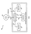
- FIG. 6 is a block diagram 600 illustrating an exemplary central switch configuration 602 for the multiserver platform of FIG. 1 , in accordance with various aspects of the invention.
- the central switch configuration 602 may include a central switch, a switching element or a switch 603, a multiserver platform #1 604, a multiserver platform #2 605, up to and including a multiserver platform #N 606.
- the multiserver platform #1 604 may include a common switch blade or switch blade 607.
- the multiserver platform #2 605 may include a switch blade 608 and the multiserver platform #N 606 may include a switch blade 609.
- the external network 601 may interface with the switch blade 607 of the multiserver platform #1 604 via a high speed communication link 610.
- the multiserver platform #1 404 may be coupled to the central switch 603 via a high speed communication link 611.
- the multiserver platform #2 605 may be coupled to the central switch 603 via the high speed link 612 and in a similar manner, the multiserver platform #N 606 may be coupled to the central switch 603 via the high speed communication link 613.
- the switch blade 607 of the multiserver platform #1 404 may interface with the central switch 603 via the high speed communication link 611.
- the switch blade 608 of the multiserver platform #2 605 may connect with the central switch 603 via the high speed communication link 612.
- the switch blade 609 of the multiserver platform #N 606 may connect to the central switch 603 via the high speed communication link 613.
- the central switch may coordinate the high speed switching or routing of packets among the various multiserver platforms 604, 605, ..., 606.
- One advantage of the central switch configuration of FIG. 6 over the daisy-chain configuration of FIG. 3 is that, in the central switch configuration of FIG. 6 , a packet may be transmitted from any given multiserver platform 604, 605, ..., 606, through the central switch 603, to any other multiserver platform.
- a packet of data may have to be passed through a plurality of intermediate multiserver platforms in order to be transferred to from a source platform to a destination platform.
- the high speed communication links 610, 611, 612, 613 may be bi-directional communication links.
- the high speed communication links may be links of the order of 1-10 Gigabits per second. Notwithstanding, these links may be Ethernet links or fibre channel links.
- the switch blades 607, 608, 609 of the multiserver platforms 604, 605, 606 may have the capability to simultaneously communicate with the central switch 603 via the high speed communication links 611, 612, ..., 613.
- the switch blade 607 may also have the capability to communicate with the external network 601 and the central switch 603 at the same time over the high speed communication links 610 and 611.
- the data communication rate between any of the multiserver platforms 604, 605, ..., 606 and the central switch 403 may be any standard or non-standard data rate, in accordance with various embodiments of the invention.
- FIG. 7 is a flowchart 700 illustrating exemplary steps for providing communication in the central switch configuration of FIG. 6 in accordance with an embodiment of the invention.
- a first multiserver platform may transmit a first packet of information to a central switch via a first high speed communication link.
- the central switch may transmit the first packet to a second multiserver platform via a second high speed communication link.
- the second multiserver platform may process the first packet and may transmit a second packet of information to the central switch via the second high speed communication link.
- the central switch may transmit the second packet to the first multiserver platform via the first high speed communication link.
- the first multiserver platform may process the second packet and may transmit a third packet of information over an external network via a third high speed communication link.
- the multiserver platforms may communicate data and/or control information among each other via one or more high speed communication links that may be coupled to the switch blades of the multiserver platforms and/or the central switch where present.
- the control information may include pertinent information related the multiserver platforms. For example, some control information may indicate the blade server associated with a particular multiserver platform from which a particular packet may have originated. Other exemplary information may include synchronization information, security information, and provisioning and security.
- any one or more of the multiserver platforms may each provide a plurality of server functions.
- each of the multiserver platforms may be dedicated to providing a different, specific server function.
- the configurations of FIG. 3 and FIG. 6 may provide blade server scalability by utilizing at least two multiserver platforms to increase server performance and/or system capacity, for example.
- multiserver platforms may be added or removed to facilitate increased and decreased traffic, respectively.
- aspects of the invention provide a method and system for inter-platform blade server integration using a plurality of multiserver platforms.
- the configurations of FIG. 3 and FIG. 6 may provide blade server scalability using a plurality of multiserver platforms to increase server performance and/or system capacity.
- a larger virtual server platform is effectively created.
- aspects of the system for processing information in a server platform may include a first multiserver platform 303 ( FIG. 3 ) having at least one network interface 309 and/or a first switch blade 306.
- At least a second multiserver platform 304 comprising a second switch blade 307 may be coupled to the first switch blade 306 of the first multiserver platform 303.
- a third multiserver platform 305 comprising a third switch blade 308 may be coupled to the second switch blade 304 of the second multiserver platform 307 and/or the first switch blade 306 of the first multiserver platform 303.
- the first multiserver platform 303, the second multiserver platform 304 and the third multiserver platform 305 may be coupled in a daisy-chain configuration.
- the first multiserver platform 303 and the third multiserver platform 305 may communicate via the second multiserver platform 304.
- At least one central switch 603 may be coupled to the first switch blade 607 of the first multiserver platform 604 and the second switch blade 608 of the second multiserver platform 605.
- At least a third switch blade 609 of a third multiserver platform 606 may also be coupled to the central switch 603.
- the first multiserver platform 604, second multiserver platform 605 and third multiserver platform 606 may communicate via the central switch 603.
- the present invention may be realized in hardware, software, or a combination of hardware and software.
- the present invention may be realized in a centralized fashion in one computer system, or in a distributed fashion where different elements are spread across several interconnected computer systems. Any kind of computer system or other apparatus adapted for carrying out the methods described herein is suited.
- a typical combination of hardware and software may be a general-purpose computer system with a computer program that, when being loaded and executed, controls the computer system such that it carries out the methods described herein.
- the present invention may also be embedded in a computer program product, which comprises all the features enabling the implementation of the methods described herein, and which when loaded in a computer system is able to carry out these methods.
- Computer program in the present context means any expression, in any language, code or notation, of a set of instructions intended to cause a system having an information processing capability to perform a particular function either directly or after either or both of the following: a) conversion to another language, code or notation; b) reproduction in a different material form.
Description
- Certain embodiments of the invention relate to communication among servers. More specifically, certain embodiments of the invention relate to a method and system for integrating multiserver platforms.
- A server may be a computer system in a network that may be accessed by one or more users and/or other computers. The server may provide, for example, access to information such as files, and to services such as communications, printing or other types of services that may be available through a network. In some cases, a special network operating system (OS) may run on a dedicated server, for example, in a large network. A personal computer (PC) operating system may run on a non-dedicated server having, for example, peer-to-peer networking software running thereon.
- Generally, a server may have one or more advanced or more powerful central processing units (CPUs), a larger memory, a larger cache and more storage space than a typical single user workstation or personal computer. The server may include, for example, multiple processors which may be dedicated to a particular service or provide a particular function such as e-mail handling, printing or communications. The server may also include devices such as, large power supplies, backup power capabilities such as an uninterruptible power supply (UPS) and various fault tolerant or redundant features such as redundant array of independent disks (RAID) technologies.
- A single server may exist in a standalone enclosure and may interface with a network via one or more network interfaces. Multiple standalone boxes may be situated in a central computing center with each standalone box coupled to a network via a respective cable. Each server may interface to the network separately at a particular data rate such as, for example, approximately 1 gigabits/second (Gb/s) for a Gigabit Ethernet or approximately 10 Gb/s for a 10 Gigabit Ethernet.
- Thus, the single server in a standalone enclosure may inefficiently utilize large amounts of space and/or power. Furthermore, since each single server may be connected to the network directly via a respective cable, a room full of servers might be overflowing with cables possibly necessitating detailed cable maps which may be quite time-intensive and costly to produce. In addition, single servers in a standalone enclosure may not be easily replaced during failure, particularly when there may be multiple failures. Consequently, the conventional single server in a standalone box may ultimately suffer from a substantial total cost of ownership (TCO).
- Further limitations and disadvantages of conventional and traditional approaches will become apparent to one of skill in the art, through comparison of such systems with some aspects of the present invention as set forth in the remainder of the present application with reference to the drawings.
-
US 2003/030988 A1 discloses a midplane which provides connectivity among a plurality of server blades and a combined switch and service processor. - Also
US 2002/188718 A1 discloses a midplane including a communication bus to couple server processing cards and network interface cards. - Certain embodiments of the invention provide a method and system for communicating information in a server platform. Aspects of the method for communicating information in a server platform may include receiving at least one packet from a first switch blade associated with a first multiserver platform comprising at least a first server blade. The method may also include determining a second server blade associated with a second multiserver platform that may receive at least a portion of the received packet. In this regard, at least a portion of the received packet may be routed to the second blade server. A backplane of the first multiserver platform and the first switch blade, which is part of the backplane, provide connectivity between the at least one first server blade and a network. The packet may be received by a second switch blade and/or a central switch. In instances where the packet may be received by the central switch, at least a portion of the received packet may be communicated to the second switch blade via at least one communication link that may couple the central switch directly to the second switch blade. The routed portion of the received packet may be processed by the second blade server.
- Aspects of the system for processing information in a multiserver platform may include a first multiserver platform having a network interface and/or a first switch blade. At least a second multiserver platform comprising a second switch blade may be coupled to the first switch blade of the first multiserver platform. A third multiserver platform comprising a third switch blade may be coupled to the second switch blade of the second multiserver platform and/or the first switch blade of the first multiserver platform. The first multiserver platform, the second multiserver platform and the third multiserver platform may be coupled in a daisy-chain configuration. In this regard, the first multiserver platform and the third multiserver platform may communicate via the second multiserver platform.
- In another embodiment of the invention, at least one central switch may be coupled to the first switch blade of the first multiserver platform and the second switch blade of the second multiserver platform. At least a third switch blade of a third multiserver platform may also be coupled to the central switch. The first multiserver platform, second multiserver platform and third multiserver platform may communicate via the central switch.
- According to another aspect of the invention, a method for communicating information in a server platform, the method comprises:
- receiving at least one packet from a first switch blade associated with a first multiserver platform comprising at least a first server blade;
- determining at least a second server blade associated with a second multiserver platform for receiving at least a portion of said received at least one packet; and
- routing at least a portion of said at least one received packet to at least said second server blade. A backplane of the first multiserver platform and the first switch blade, which is part of the backplane, provide connectivity between the at least one first server blade and a network.
- Advantageously, said receiving further comprises receiving said at least one packet by a second switch blade and a central switch.
- Advantageously, said at least one packet is received by said central switch, communicating said at least a portion of said at least one received packet to at least said second switch blade via at least one communication link that couples said central switch directly to said at least said second switch blade.
- Advantageously, the method further comprises processing said routed at least a portion of said at least one received packet by said at least said second blade server.
- According to another aspect of the invention, a system for communicating information in a server platform, the system comprises:
- a first multiserver platform comprising at least a first server blade and at least one of a network interface and a first switch blade; and
- at least a second multiserver platform comprising a second switch blade coupled said first switch blade of said first multiserver platform.
- A backplane of the first multiserver platform and the first switch blade, which is part of the backplane, provide connectivity between the at least one first server blade and a network. Advantageously, the system further comprises at least a third multiserver platform comprising a third switch blade coupled to at least one of said second switch blade of said second multiserver platform and said first switch blade of said first multiserver platform.
- Advantageously, said first multiserver platform, said second multiserver platform and said third multiserver are coupled in a daisy-chain configuration.
- Advantageously, said first multiserver platform, and said third multiserver platform communicate via said second multiserver platform.
- Advantageously, the system further comprises at least one central switch coupled to at least said first switch blade of said first multiserver platform and said second switch blade of said second multiserver platform.
- Advantageously, the system further comprises at least a third switch blade of a third multiserver platform coupled to said at least one central switch.
- Advantageously, said first multiserver platform, said second multiserver platform and said third multiserver platform communicate via said central switch.
- These and other advantages, aspects and novel features of the present invention, as well as details of an illustrated embodiment thereof, will be more fully understood from the following description and drawings.
-
FIG. 1 is a block diagram of an embodiment of a multiserver platform in accordance with an embodiment of the invention. -
FIG. 2 is a block diagram illustrating an embodiment of a communication system including a multiserver platform and an external network in accordance with various aspects of the invention. -
FIG. 3 is a block diagram illustrating an embodiment of a communication system including an external network and N multiserver platforms coupled in a daisy-chain configuration in accordance with an embodiment of the invention. -
FIG. 4 is a block diagram illustrating the coupling of two switch blades in accordance with an embodiment of the invention. -
FIG. 5 is a flowchart illustrating exemplary steps for providing communication within the daisy-chain configuration ofFIG. 3 in accordance with an embodiment of the invention. -
FIG. 6 is a block diagram illustrating an exemplary central switch configuration for the multiserver platform ofFIG. 1 , in accordance with various aspects of the invention. -
FIG. 7 is a flowchart illustrating exemplary steps for providing communication in the central switch configuration ofFIG. 6 in accordance with an embodiment of the invention. - Certain embodiments of the invention provide a method and system for communicating information in a server platform. Aspects of the method for communicating information in a multiserver platform may include receiving at least one packet from a first switch blade associated with a first multiserver platform. Another aspect of the method may include determining a second server blade associated with a second multiserver platform that may receive at least a portion of the received packet. In this regard, at least a portion of the received packet may subsequently be routed to the second blade server and the routed portion of the received packet processed by the second blade server. In another aspect of the invention, the packet may be received by a third switch blade and/or a central switch. Accordingly, in instances where the packet may be received by the central switch, at least a portion of the received packet may be communicated to the second switch blade via one or more communication links that may be utilized to couple the central switch directly to the second switch blade.
-
FIG. 1 is a block diagram of an embodiment of amultiserver platform 100 in accordance with an embodiment of the invention. Themultiserver platform 100 may include achassis 110, abackplane 130, aswitch blade 140, blade server interfaces 150, and a plurality of blade servers No. 1, No. 2, ..., No. n, collectively referenced as 120. - The
chassis 110 may include the backplane'130. However, although only onebackplane 130 is shown, the invention is not so limited and a plurality of backplanes may be provided within thechassis 110. In this regard, one or more backplanes may be coupled together. In a case where thechassis 110 may include a single backplane, the backplane may be regarded as a common backplane, which may provide connectivity for theblade servers 120. Thechassis 110 may be part of a single installation enclosure that includes a plurality of blade server slots which may be adapted for receiving one or more of theblade servers 120. - The
backplane 130 may include, for example, one or more blade server interfaces collectively referenced as 150, which may be referred to as blade server interconnects. In this regard, thechassis 110 may include a plurality of blade server slots that may be adapted to facilitate connection between the blade servers and the blade server interfaces 150. In other words, the blade server slots may provide a conduit for coupling theblade servers 120 to the blade server interfaces 150. Thebackplane 130 may also include one or more interfaces such as anetwork interface 160. Thenetwork interface 160 may be referred to as network interconnect. - The
switch blade 140 may be part of thebackplane 130. In this regard, theswitch blade 140 may be integrated within thebackplane 130 or it may be a plug-in card that may be plugged into thebackplane 130. - The
blade servers 120 may be coupled to thebackplane 130 via the blade server interfaces 150. Each of theblade servers 120 may therefore be coupled to a corresponding one of the server interfaces 150. For example, each of theblade servers 120 may be plugged into or removably mounted in a corresponding blade server slot in thechassis 110 so that it interfaces with a corresponding one of the server interfaces. In this regard, theblade servers 120 may be coupled to thebackplane 130. - Once the
blade servers 120 are mounted or plugged into thechassis 110, theblade servers 120 may be coupled to theswitch blade 140 of thebackplane 130 via the blade server interfaces 150. Thebackplane 130 may be adapted to provide connectivity, for example, between two or more of theblade servers 120. Furthermore, thebackplane 130 and/or theswitch blades 140 may provide connectivity between the one or more of theblade servers 120 and thenetwork 170. - The
network interface 160 facilitates connectivity between thebackplane 130 and thenetwork 170. In this regard, thenetwork interface 160 may couplebackplane 130 and/or one or more of the plurality ofswitch blades 140 to thenetwork 170. -
FIG. 2 is a block diagram illustrating an embodiment of acommunication system 200 including amultiserver platform 201 and anexternal network 206, in accordance with various aspects of the invention. Themultiserver platform 201 may include a chassis having acommon backplane 211, a common switch-blade 202 and a plurality of blade servers including, ablade server # 1 203, ablade server # 2 204, ..., bladeserver #N 205, where N may be any integer number. - Each of the
blade servers # 1, #2, ..., #N may be a server that has been integrated on a single plug-in card or blade that may be plugged into a blade server slot of the chassis with thecommon backplane 211. The chassis with acommon backplane 211 may provide a single installation enclosure for the multipleblade servers # 1, #2, .., #N. - The chassis with the
common backplane 211 may also serve a common interface between eachblade server common switch blade 202. For example,common backplane 211 may provide acommon backplane interface 208 betweenblade server # 1 203 and thecommon switch blade 202.Common backplane 211 may also provide acommon backplane interface 209 betweenblade server # 2 204 and thecommon switch blade 202. Finally,common backplane 211 may provide acommon backplane interface 210 between bladeserver #N 205 and thecommon switch blade 202. In this regard, thecommon backplane interfaces common backplane 211. - The
common switch blade 202 may include N+1 interfaces and at least a portion of these interfaces may be adapted to perform packet switching of data frames between the N blade servers and theexternal network 206, in accordance with an embodiment of the invention. The common switch-blade may include intelligence that may manage and distribute data traffic to the relevant blade servers includingblade server # 1, #2, ..., #N. The common switch-blade 202 may interface with each of the N blade servers via thecommon backplane 211. The common switch-blade 202 may also interface with theexternal network 206, thereby resulting in N+1 interfaces. - In accordance with an embodiment of the invention, the
external network 206 may include a 10 Gigabit Ethernet network connection and interface. Theexternal interface 207 between thecommon switch blade 202 and theexternal network 206 may include a 10 Gigabit Ethernet (GbE) interface, operating at a data rate of 10 Gb/s. In this regard, bi-directional network communication capability may be provided between theexternal network 206 and thecommon switch blade 202. In order to facilitate Gigabit Ethernet communication, thecommon backplane 211 may include a plurality of Gigabit Ethernet (GbE) interfaces. Theswitch blade 202 may communicate with each of the N blade servers independently over thecommon backplane 211 at a data rate of 1 Gb/s. For example, theblade server # 1 203 may communicate in a bi-directional manner with the common switch-blade 202 via thecommon backplane interface 208. Theblade server # 2 204 may also communicate in a bi-directional manner with thecommon switch blade 202 via thecommon backplane interface 209. Finally, the blade server #N 105 may communicate in a bi-directional manner with thecommon switch blade 202 via thecommon backplane interface 210. - In accordance with an embodiment of the invention, the
common switch blade 202 may have the capability to handle communication with themultiple blade servers common blade server 202 may facilitate the simultaneous transfer of information between any of theblade servers -
FIG. 3 is a block diagram illustrating an embodiment of acommunication system 300 including anexternal network 301 and N multiserver platforms coupled in a daisy-chain configuration in accordance with an embodiment of the invention. The daisy-chain configuration includes N multiserver platforms referenced as 303, 304, ..., 305 and labeled asmultiserver platform # 1,multiserver platform # 2, ..., multiserver platform #N, respectively. Referring toFIG. 3 , themultiserver platform # 1 303 may include acommon switch blade 306. Themultiserver platform # 2 304 may include acommon switch blade 307 and the multiserverplatform #N 305 includes acommon switch blade 308. - The
external network 301 may interface with theswitch blade 306 of themultiserver platform # 1 303 via, for example, a highspeed communication link 309. Themultiserver platform # 1,multiserver platform # 2, ..., multiserver platforms #N referenced as 303, 305, ..., 305 may be coupled together in a daisy-chained arrangement via, for example, high speed communication links. For example, theswitch blade 306 of themultiserver platform # 1 303 may interface with theswitch blade 307 of the multiserver platform #3 via a highspeed communication link 310. Theswitch blade 307 of themultiserver platform # 2 304 may also interface with the switch blade of another multiserver platform via a highspeed communication link 311. Theswitch blade 308 of the multiserverplatform #N 305 may also interface with the switch blade of some other multiserver platform via a highspeed communication link 312. - The high
speed communication links switch blades switch blade 306 may be adapted to communicate with theexternal network 301 and theswitch blade 307 at the same time over the highspeed communication links switch blades multiserver platforms multiserver platforms -
FIG. 4 is a block diagram illustrating the coupling of two switch blades in accordance with an embodiment of the invention. Referring toFIG. 4 , there is shown afirst multiserver platform 402 coupled to asecond multiserver platform 422. In this regard,reference 402 may include an enclosure or chassis of thefirst multiserver platform 402 andreference 422 may include an enclosure or chassis of themultiserver platform 422. Notwithstanding, thefirst multiserver platform 402 may include abackplane 404, a plurality of n blade servers collectively referred to as 406, aswitch blade 408 and abus 411. Also shown arebus transceivers controller 418. Each of thebus transceivers bus 411 within thebackplane 404. Each of thebus transceivers bus 411 within thebackplane 404. Thebus 411 may be a time division multiplexed (TDM) bus, a frequency division multiplexed (FDM) bus, or any other suitable type of bus. Accordingly, thebus transceivers communication link 440 may couple thefirst multiserver platform 402 to thesecond multiserver platform 422. Thecommunication link 440 may be similar to the communication links that couple themultiserver platform # 1,multiserver platform # 2, ..., multiserver platform #N referenced as 303, 304, ..., 305 in the daisy-chain arrangement ofFIG. 3 . - Each of the
blade servers 406 and theswitch blade 408 of thefirst multiserver platform 402 may include a bus transceiver that may be coupled to thebus 411. In this regard, blade server No. 1 includes abus transceiver 410, server blade No. 2 includes abus transceiver 412, and server blade No. n includes abus transceiver 414. Theswitch blade 408 may also include abus transceiver 416 and abus controller 418. Although thebus controller 418 is illustrated as a separate entity within theswitch blade 408, the invention is not so limited. Accordingly, one or more functions provided by thebus controller 418 may be provided by theswitch blade 408. In a case where all of the functions offered by the bus controller may be provided by the switch blade, this may eliminate a need for an additional bus processing entity such as thebus controller 418. - Notwithstanding, the
bus controller 418 and/or theswitch blade 408 of thefirst multiserver platform 402 may be adapted to control the transfer of messages between theblade servers 406 and theswitch blade 408. In this regard, thebus controller 418 may handle functions such as bus access and bus arbitration. Thebus controller 418 and/or theswitch blade 408 may also provide a switching function that may permit messages to be transferred among theblade servers 406 via the switch blade and from an external source such as the network 170 (FIG. 1 ) to any one or more of theblade servers 406. For example, one or more messages received from thenetwork 170 may be steered by theswitch blade 408 to one or more of theblade servers 406 based on a message type and a function provided by one or more of theblade servers 406. - The
bus controller 418 and/or theswitch blade 408 of thefirst multiserver platform 402 may include suitable hardware and/or software that may be adapted to control, for example, bus access, bus arbitration and/or switching among theblade servers 406 and theswitch blade 408. The hardware and/or software may therefore control the manner in which messages may be received from a first blade server and transferred, routed or switched to a second blade server via theswitch blade 408. - The
second multiserver platform 422 may include abackplane 424, a plurality of n blade servers collectively referred to as 426, aswitch blade 428 and abus 431. Also shown arebus transceivers controller 438. Each of thebus transceivers bus 431 within thebackplane 424. Each of thebus transceivers bus 431 within thebackplane 424. Thebus 431 may be a time division multiplexed (TDM) bus, a frequency division multiplexed (FDM) bus, or any other suitable type of bus. Accordingly, thebus transceivers - Each of the
blade servers 426 and theswitch blade 428 of thesecond multiserver platform 422 may include a bus transceiver that may be coupled to thebus 431. In this regard, blade server No. 1 includes abus transceiver 430, server blade No. 2 includes abus transceiver 432, and server blade No. n includes abus transceiver 434. Theswitch blade 428 may also include a bus transceiver 436 and abus controller 438. Although thebus controller 438 is illustrated as a separate entity within theswitch blade 438, the invention is not so limited. Accordingly, one or more functions provided by thebus controller 438 may provided by theswitch blade 428. In a case where all of the functions offered by the bus controller may be provided by the switch blade, this may eliminate a need for an additional bus processing entity such as thebus controller 438. - Notwithstanding, the
bus controller 438 and/or theswitch blade 428 of thesecond multiserver platform 422 may be adapted to control the transfer of messages between theblade servers 426 and theswitch blade 428. In this regard, thebus controller 438 may handle functions such as bus access and bus arbitration. Thebus controller 438 and/or theswitch blade 428 may also provide a switching function that may permit messages to be transferred among theblade servers 426 via the switch blade and from an external source such as the network 170 (FIG. 1 ) to any one or more of theblade servers 426. For example, one or more messages received from thenetwork 170 may be steered by theswitch blade 428 to one or more of theblade servers 426 based on a message type and a function provided by one or more of theblade servers 426. - The
bus controller 438 and/or theswitch blade 428 of thesecond multiserver platform 422 may include suitable hardware and/or software that may be adapted to control, for example, bus access, bus arbitration and/or switching among theblade servers 426 and theswitch blade 428. The hardware and/or software may therefore control the manner in which messages may be received from a first blade server and transferred, routed or switched to a second blade server via theswitch blade 428. -
FIG. 5 is aflowchart 500 illustrating exemplary steps for providing communication within the daisy-chain configuration 302 ofFIG. 3 in accordance with an embodiment of the invention. Referring toFIG. 5 , instep 501, a first multiserver platform may transmit a first packet of information to a second multiserver platform via a first high speed communication link. Instep 502, the second multiserver platform may process the first packet and transmit a second packet of information to a third multiserver platform via a second high speed communication link. Instep 503, the third multiserver platform may process the second packet and transmit a third packet of information to the second multiserver platform via the second high speed communication link. Instep 504, the second multiserver platform may process the third packet and transmit a fourth packet of information to the first multiserver platform via the first high speed communication link. Instep 505, the first multiserver platform may process the fourth packet and transmit a fifth packet of information over an external network via a third high speed communication link. -
FIG. 6 is a block diagram 600 illustrating an exemplarycentral switch configuration 602 for the multiserver platform ofFIG. 1 , in accordance with various aspects of the invention. Thecentral switch configuration 602 may include a central switch, a switching element or aswitch 603, amultiserver platform # 1 604, amultiserver platform # 2 605, up to and including a multiserverplatform #N 606. Themultiserver platform # 1 604 may include a common switch blade orswitch blade 607. Themultiserver platform # 2 605 may include aswitch blade 608 and the multiserverplatform #N 606 may include aswitch blade 609. - The
external network 601 may interface with theswitch blade 607 of themultiserver platform # 1 604 via a highspeed communication link 610. Themultiserver platform # 1 404 may be coupled to thecentral switch 603 via a highspeed communication link 611. Themultiserver platform # 2 605 may be coupled to thecentral switch 603 via thehigh speed link 612 and in a similar manner, the multiserverplatform #N 606 may be coupled to thecentral switch 603 via the highspeed communication link 613. In this regard, theswitch blade 607 of themultiserver platform # 1 404 may interface with thecentral switch 603 via the highspeed communication link 611. Theswitch blade 608 of themultiserver platform # 2 605 may connect with thecentral switch 603 via the highspeed communication link 612. In a similar manner, theswitch blade 609 of the multiserverplatform #N 606 may connect to thecentral switch 603 via the highspeed communication link 613. - In operation, the central switch may coordinate the high speed switching or routing of packets among the various
multiserver platforms FIG. 6 over the daisy-chain configuration ofFIG. 3 is that, in the central switch configuration ofFIG. 6 , a packet may be transmitted from any givenmultiserver platform central switch 603, to any other multiserver platform. In the daisy-chain configuration or arrangement, a packet of data may have to be passed through a plurality of intermediate multiserver platforms in order to be transferred to from a source platform to a destination platform. - The high
speed communication links switch blades multiserver platforms central switch 603 via the highspeed communication links switch blade 607 may also have the capability to communicate with theexternal network 601 and thecentral switch 603 at the same time over the highspeed communication links multiserver platforms -
FIG. 7 is aflowchart 700 illustrating exemplary steps for providing communication in the central switch configuration ofFIG. 6 in accordance with an embodiment of the invention. Referring toFIG. 7 , instep 701, a first multiserver platform may transmit a first packet of information to a central switch via a first high speed communication link. Instep 702, the central switch may transmit the first packet to a second multiserver platform via a second high speed communication link. Instep 703, the second multiserver platform may process the first packet and may transmit a second packet of information to the central switch via the second high speed communication link. Instep 704, the central switch may transmit the second packet to the first multiserver platform via the first high speed communication link. Instep 705, the first multiserver platform may process the second packet and may transmit a third packet of information over an external network via a third high speed communication link. - In accordance with various embodiments of the invention, the multiserver platforms may communicate data and/or control information among each other via one or more high speed communication links that may be coupled to the switch blades of the multiserver platforms and/or the central switch where present. The control information may include pertinent information related the multiserver platforms. For example, some control information may indicate the blade server associated with a particular multiserver platform from which a particular packet may have originated. Other exemplary information may include synchronization information, security information, and provisioning and security.
- In accordance with another embodiment of the invention, any one or more of the multiserver platforms may each provide a plurality of server functions. Alternatively, each of the multiserver platforms may be dedicated to providing a different, specific server function. Notwithstanding, the configurations of
FIG. 3 andFIG. 6 may provide blade server scalability by utilizing at least two multiserver platforms to increase server performance and/or system capacity, for example. In this regard, multiserver platforms may be added or removed to facilitate increased and decreased traffic, respectively. - Aspects of the invention provide a method and system for inter-platform blade server integration using a plurality of multiserver platforms. The configurations of
FIG. 3 andFIG. 6 , for example, may provide blade server scalability using a plurality of multiserver platforms to increase server performance and/or system capacity. In this regard, by integrating a plurality of multiserver platforms, a larger virtual server platform is effectively created. - In particular, for example, aspects of the system for processing information in a server platform may include a first multiserver platform 303 (
FIG. 3 ) having at least onenetwork interface 309 and/or afirst switch blade 306. At least asecond multiserver platform 304 comprising asecond switch blade 307 may be coupled to thefirst switch blade 306 of thefirst multiserver platform 303. Athird multiserver platform 305 comprising athird switch blade 308 may be coupled to thesecond switch blade 304 of thesecond multiserver platform 307 and/or thefirst switch blade 306 of thefirst multiserver platform 303. Thefirst multiserver platform 303, thesecond multiserver platform 304 and thethird multiserver platform 305 may be coupled in a daisy-chain configuration. In this regard, thefirst multiserver platform 303 and thethird multiserver platform 305 may communicate via thesecond multiserver platform 304. - In another embodiment of the invention, for example, at least one central switch 603 (
FIG. 6 ) may be coupled to thefirst switch blade 607 of thefirst multiserver platform 604 and thesecond switch blade 608 of thesecond multiserver platform 605. At least athird switch blade 609 of athird multiserver platform 606 may also be coupled to thecentral switch 603. Thefirst multiserver platform 604,second multiserver platform 605 and thirdmultiserver platform 606 may communicate via thecentral switch 603. - Accordingly, the present invention may be realized in hardware, software, or a combination of hardware and software. The present invention may be realized in a centralized fashion in one computer system, or in a distributed fashion where different elements are spread across several interconnected computer systems. Any kind of computer system or other apparatus adapted for carrying out the methods described herein is suited. A typical combination of hardware and software may be a general-purpose computer system with a computer program that, when being loaded and executed, controls the computer system such that it carries out the methods described herein.
- The present invention may also be embedded in a computer program product, which comprises all the features enabling the implementation of the methods described herein, and which when loaded in a computer system is able to carry out these methods. Computer program in the present context means any expression, in any language, code or notation, of a set of instructions intended to cause a system having an information processing capability to perform a particular function either directly or after either or both of the following: a) conversion to another language, code or notation; b) reproduction in a different material form.
- While the present invention has been described with reference to certain embodiments, it will be understood by those skilled in the art that various changes may be made and equivalents may be substituted without departing from the scope of the present invention. In addition, many modifications may be made to adapt a particular situation or material to the teachings of the present invention without departing from its scope. Therefore, it is intended that the present invention not be limited to the particular embodiment disclosed, but that the present invention will include all embodiments falling within the scope of the appended claims.
Claims (6)
- A method for communicating information in a server platform (300, 600), the method comprising:receiving at least one packet from a first switch blade (306, 607) associated with a first multiserver platform (303, 604) comprising at least a first server blade;determining at least a second server blade associated with a second multiserver platform (304, 605) for receiving at least a portion of said received at least one packet; androuting at least a portion of said at least one received packet to at least said second server blade,characterized in thata backplane of the first multiserver platform (303, 604) and the first switch blade (306, 607), which is part of the backplane, provide connectivity between the at least one first server blade and a network (301, 601).
- The method according to claim 1, wherein said receiving further comprises receiving said at least one packet by a second switch blade (608) and a central switch (603).
- The method according to claim 2, further comprising if said at least one packet is received by said central switch (603), communicating said at least a portion of said at least one received packet to at least said second switch blade (608) via at least one communication link (612) that couples said central switch (603) directly to said at least said second switch blade (608).
- The method according to claim 1, further comprising processing said routed at least a portion of said at least one received packet by said at least said second blade server.
- A system for communicating information in a server platform, the system comprising:a first multiserver platform (303, 604) comprising at least a first server blade and at least one of a network interface and a first switch blade (306, 607); andat least a second multiserver platform (304, 605) comprising a second switch blade (307, 608) coupled said first switch blade (306, 607) of said first multiserver platform (303, 604),characterized in thata backplane of the first multiserver platform (303, 604) and the first switch blade (306, 607), which is part of the backplane, provide connectivity between the at least one first server blade and a network (301, 601).
- The system according to claim 5, further comprising at least a third multiserver platform (305, 606) comprising a third switch blade (308, 609) coupled to at least one of said second switch blade (307, 608) of said second multiserver platform (304, 605) and said first switch blade (306, 607) of said first multiserver platform (303, 604).
Applications Claiming Priority (8)
| Application Number | Priority Date | Filing Date | Title |
|---|---|---|---|
| US44865603P | 2003-02-18 | 2003-02-18 | |
| US448656P | 2003-02-18 | ||
| US45683103P | 2003-03-21 | 2003-03-21 | |
| US456831P | 2003-03-21 | ||
| US45871903P | 2003-03-28 | 2003-03-28 | |
| US458719P | 2003-03-28 | ||
| US46301403P | 2003-04-15 | 2003-04-15 | |
| US463014P | 2003-04-15 |
Publications (3)
| Publication Number | Publication Date |
|---|---|
| EP1450537A2 EP1450537A2 (en) | 2004-08-25 |
| EP1450537A3 EP1450537A3 (en) | 2005-03-23 |
| EP1450537B1 true EP1450537B1 (en) | 2008-03-26 |
Family
ID=32738907
Family Applications (3)
| Application Number | Title | Priority Date | Filing Date |
|---|---|---|---|
| EP04001859A Expired - Fee Related EP1450539B1 (en) | 2003-02-18 | 2004-01-28 | System and method for communicating using a multiserver platform |
| EP04001857A Expired - Fee Related EP1450537B1 (en) | 2003-02-18 | 2004-01-28 | System and method for integrating multiserver platforms |
| EP04001858A Expired - Fee Related EP1450538B1 (en) | 2003-02-18 | 2004-01-28 | System and method for communicating between servers using a multiserver platform |
Family Applications Before (1)
| Application Number | Title | Priority Date | Filing Date |
|---|---|---|---|
| EP04001859A Expired - Fee Related EP1450539B1 (en) | 2003-02-18 | 2004-01-28 | System and method for communicating using a multiserver platform |
Family Applications After (1)
| Application Number | Title | Priority Date | Filing Date |
|---|---|---|---|
| EP04001858A Expired - Fee Related EP1450538B1 (en) | 2003-02-18 | 2004-01-28 | System and method for communicating between servers using a multiserver platform |
Country Status (3)
| Country | Link |
|---|---|
| US (6) | US7966422B2 (en) |
| EP (3) | EP1450539B1 (en) |
| DE (2) | DE602004012633T2 (en) |
Families Citing this family (54)
| Publication number | Priority date | Publication date | Assignee | Title |
|---|---|---|---|---|
| US7444398B1 (en) * | 2000-09-13 | 2008-10-28 | Fortinet, Inc. | System and method for delivering security services |
| US7574495B1 (en) * | 2000-09-13 | 2009-08-11 | Fortinet, Inc. | System and method for managing interworking communications protocols |
| US8250357B2 (en) | 2000-09-13 | 2012-08-21 | Fortinet, Inc. | Tunnel interface for securing traffic over a network |
| US7487232B1 (en) * | 2000-09-13 | 2009-02-03 | Fortinet, Inc. | Switch management system and method |
| US7111072B1 (en) | 2000-09-13 | 2006-09-19 | Cosine Communications, Inc. | Packet routing system and method |
| US7389358B1 (en) | 2000-09-13 | 2008-06-17 | Fortinet, Inc. | Distributed virtual system to support managed, network-based services |
| US7272643B1 (en) | 2000-09-13 | 2007-09-18 | Fortinet, Inc. | System and method for managing and provisioning virtual routers |
| US7181547B1 (en) | 2001-06-28 | 2007-02-20 | Fortinet, Inc. | Identifying nodes in a ring network |
| US7124171B1 (en) * | 2002-05-23 | 2006-10-17 | Emc Corporation | In a networked computing cluster storage system and plurality of servers sharing files, in the event of server unavailability, transferring a floating IP network address from first server to second server to access area of data |
| US7177311B1 (en) | 2002-06-04 | 2007-02-13 | Fortinet, Inc. | System and method for routing traffic through a virtual router-based network switch |
| US7376125B1 (en) | 2002-06-04 | 2008-05-20 | Fortinet, Inc. | Service processing switch |
| US7161904B2 (en) | 2002-06-04 | 2007-01-09 | Fortinet, Inc. | System and method for hierarchical metering in a virtual router based network switch |
| US7203192B2 (en) * | 2002-06-04 | 2007-04-10 | Fortinet, Inc. | Network packet steering |
| US7096383B2 (en) | 2002-08-29 | 2006-08-22 | Cosine Communications, Inc. | System and method for virtual router failover in a network routing system |
| US7266120B2 (en) * | 2002-11-18 | 2007-09-04 | Fortinet, Inc. | System and method for hardware accelerated packet multicast in a virtual routing system |
| US7835363B2 (en) * | 2003-02-12 | 2010-11-16 | Broadcom Corporation | Method and system to provide blade server load balancing using spare link bandwidth |
| US7966422B2 (en) | 2003-02-18 | 2011-06-21 | Broadcom Corporation | System and method for communicating between servers using a multi-server platform |
| US20040181601A1 (en) * | 2003-03-14 | 2004-09-16 | Palsamy Sakthikumar | Peripheral device sharing |
| US7720095B2 (en) | 2003-08-27 | 2010-05-18 | Fortinet, Inc. | Heterogeneous media packet bridging |
| US7738242B2 (en) * | 2004-01-08 | 2010-06-15 | Hewlett-Packard Development Company, L.P. | System and method for displaying chassis component information |
| US20060048163A1 (en) * | 2004-08-27 | 2006-03-02 | Thierry Bessis | Method for routing messages between servers located on the same board |
| US7499419B2 (en) | 2004-09-24 | 2009-03-03 | Fortinet, Inc. | Scalable IP-services enabled multicast forwarding with efficient resource utilization |
| US7808904B2 (en) * | 2004-11-18 | 2010-10-05 | Fortinet, Inc. | Method and apparatus for managing subscriber profiles |
| US7519693B2 (en) * | 2004-11-18 | 2009-04-14 | International Business Machines Corporation | Apparatus, system, and method for integrating an enclosure |
| US8194534B2 (en) * | 2005-02-28 | 2012-06-05 | International Business Machines Corporation | Blade server system with at least one rack-switch having multiple switches interconnected and configured for management and operation as a single virtual switch |
| US8107822B2 (en) * | 2005-05-20 | 2012-01-31 | Finisar Corporation | Protocols for out-of-band communication |
| US20060264178A1 (en) * | 2005-05-20 | 2006-11-23 | Noble Gayle L | Wireless diagnostic systems |
| US7899057B2 (en) | 2006-04-28 | 2011-03-01 | Jds Uniphase Corporation | Systems for ordering network packets |
| US7822127B1 (en) * | 2006-05-15 | 2010-10-26 | Super Micro Computer, Inc. | Method and apparatus for minimizing signal loss in transit |
| US8437352B2 (en) * | 2006-05-30 | 2013-05-07 | Broadcom Corporation | Method and system for power control based on application awareness in a packet network switch |
| US8213333B2 (en) * | 2006-07-12 | 2012-07-03 | Chip Greel | Identifying and resolving problems in wireless device configurations |
| US7584325B2 (en) * | 2006-07-26 | 2009-09-01 | International Business Machines Corporation | Apparatus, system, and method for providing a RAID storage system in a processor blade enclosure |
| CN101227355B (en) * | 2006-08-16 | 2010-06-09 | 环达电脑(上海)有限公司 | Clustering system and system management architecture thereof |
| US8526821B2 (en) | 2006-12-29 | 2013-09-03 | Finisar Corporation | Transceivers for testing networks and adapting to device changes |
| US8214479B2 (en) * | 2007-04-02 | 2012-07-03 | Telefonaktiebolaget Lm Ericsson (Publ) | Scalability and redundancy in an MSC-Server blade cluster |
| US8139036B2 (en) * | 2007-10-07 | 2012-03-20 | International Business Machines Corporation | Non-intrusive capture and display of objects based on contact locality |
| US8625592B2 (en) * | 2008-02-26 | 2014-01-07 | Cisco Technology, Inc. | Blade switch with scalable interfaces |
| US8151273B2 (en) * | 2008-08-28 | 2012-04-03 | Microsoft Corporation | Environment wide configuration system |
| CN101853185B (en) * | 2009-03-30 | 2015-07-08 | 华为技术有限公司 | Blade server and service dispatching method thereof |
| US8139492B1 (en) | 2009-06-09 | 2012-03-20 | Juniper Networks, Inc. | Local forwarding bias in a multi-chassis router |
| US8429316B1 (en) | 2009-07-31 | 2013-04-23 | Marvell International Ltd. | Switch low power state in a blade server system |
| US8817614B1 (en) * | 2010-09-16 | 2014-08-26 | Vasona Networks Inc. | Policy enforcer having load balancing capabilities |
| JP5687959B2 (en) * | 2011-06-20 | 2015-03-25 | 株式会社日立製作所 | I / O device sharing method and apparatus |
| US9014215B2 (en) | 2011-09-22 | 2015-04-21 | Aviat U.S., Inc. | Systems and methods for synchronization of clock signals |
| CN103186409A (en) * | 2011-12-30 | 2013-07-03 | 英业达集团(天津)电子技术有限公司 | Virtual machine deployment system |
| DE102012200042A1 (en) * | 2012-01-03 | 2013-07-04 | Airbus Operations Gmbh | SERVER SYSTEM, AIR OR ROOM VEHICLE AND METHOD |
| CN103685382B (en) * | 2012-09-12 | 2017-01-25 | 中兴通讯股份有限公司 | Calling method and system of inter-clerk cross-blade server |
| US9591015B1 (en) * | 2014-03-28 | 2017-03-07 | Fireeye, Inc. | System and method for offloading packet processing and static analysis operations |
| US10805340B1 (en) | 2014-06-26 | 2020-10-13 | Fireeye, Inc. | Infection vector and malware tracking with an interactive user display |
| US9690933B1 (en) | 2014-12-22 | 2017-06-27 | Fireeye, Inc. | Framework for classifying an object as malicious with machine learning for deploying updated predictive models |
| US9838417B1 (en) | 2014-12-30 | 2017-12-05 | Fireeye, Inc. | Intelligent context aware user interaction for malware detection |
| US10148693B2 (en) | 2015-03-25 | 2018-12-04 | Fireeye, Inc. | Exploit detection system |
| DE112015006975T5 (en) * | 2015-09-25 | 2019-05-09 | Intel Corporation | Microelectronic package with wireless interconnection |
| US10496291B2 (en) | 2015-12-18 | 2019-12-03 | Sap Se | Maintaining data integrity during data migration |
Family Cites Families (53)
| Publication number | Priority date | Publication date | Assignee | Title |
|---|---|---|---|---|
| US5920566A (en) * | 1997-06-30 | 1999-07-06 | Sun Microsystems, Inc. | Routing in a multi-layer distributed network element |
| US6188571B1 (en) * | 1997-11-03 | 2001-02-13 | Aiwa Raid Technology, Inc. | High density RAID subsystem with highly integrated controller |
| US6266335B1 (en) * | 1997-12-19 | 2001-07-24 | Cyberiq Systems | Cross-platform server clustering using a network flow switch |
| US8516055B2 (en) * | 1998-05-29 | 2013-08-20 | Research In Motion Limited | System and method for pushing information from a host system to a mobile data communication device in a wireless data network |
| US6510164B1 (en) * | 1998-11-16 | 2003-01-21 | Sun Microsystems, Inc. | User-level dedicated interface for IP applications in a data packet switching and load balancing system |
| US6208647B1 (en) * | 1999-04-14 | 2001-03-27 | Verizon Laboratories Inc. | Multicast extension to data link layer protocols |
| US6597693B1 (en) * | 1999-05-21 | 2003-07-22 | Advanced Micro Devices, Inc. | Common scalable queuing and dequeuing architecture and method relative to network switch data rate |
| US6735169B1 (en) * | 1999-07-02 | 2004-05-11 | Cisco Technology, Inc. | Cascading multiple services on a forwarding agent |
| US6650641B1 (en) * | 1999-07-02 | 2003-11-18 | Cisco Technology, Inc. | Network address translation using a forwarding agent |
| US6574240B1 (en) * | 2000-01-19 | 2003-06-03 | Advanced Micro Devices, Inc. | Apparatus and method for implementing distributed layer 3 learning in a network switch |
| AU2001240004A1 (en) * | 2000-03-03 | 2001-09-17 | Qualcomm Incorporated | Method and apparatus for participating in group communication services in an existing communication system |
| US8380854B2 (en) * | 2000-03-21 | 2013-02-19 | F5 Networks, Inc. | Simplified method for processing multiple connections from the same client |
| US7111076B2 (en) * | 2000-04-13 | 2006-09-19 | Intel Corporation | System using transform template and XML document type definition for transforming message and its reply |
| US7079537B1 (en) * | 2000-04-25 | 2006-07-18 | Advanced Micro Devices, Inc. | Layer 3 switching logic architecture in an integrated network switch |
| US6816905B1 (en) * | 2000-11-10 | 2004-11-09 | Galactic Computing Corporation Bvi/Bc | Method and system for providing dynamic hosted service management across disparate accounts/sites |
| US20020107971A1 (en) * | 2000-11-07 | 2002-08-08 | Bailey Brian W. | Network transport accelerator |
| US7236490B2 (en) * | 2000-11-17 | 2007-06-26 | Foundry Networks, Inc. | Backplane interface adapter |
| US20020085567A1 (en) * | 2000-12-28 | 2002-07-04 | Maple Optical Systems, Inc. | Metro switch and method for transporting data configured according to multiple different formats |
| US7984147B2 (en) * | 2000-12-29 | 2011-07-19 | Hewlett-Packard Development Company, L.P. | Apparatus and method for identifying a requested level of service for a transaction |
| US7339786B2 (en) | 2001-03-05 | 2008-03-04 | Intel Corporation | Modular server architecture with Ethernet routed across a backplane utilizing an integrated Ethernet switch module |
| US7133869B2 (en) * | 2001-03-06 | 2006-11-07 | Knowledge Vector, Inc. | Methods and systems for and defining and distributing information alerts |
| AU2002306749A1 (en) * | 2001-03-13 | 2002-09-24 | Shiv Balakrishnan | An architecture and protocol for a wireless communication network to provide scalable web services to mobile access devices |
| US20020188718A1 (en) * | 2001-05-04 | 2002-12-12 | Rlx Technologies, Inc. | Console information storage system and method |
| US7164677B2 (en) * | 2001-05-07 | 2007-01-16 | Vitesse Semiconductor Corporation | Data switching system |
| US7102996B1 (en) * | 2001-05-24 | 2006-09-05 | F5 Networks, Inc. | Method and system for scaling network traffic managers |
| US8004971B1 (en) * | 2001-05-24 | 2011-08-23 | F5 Networks, Inc. | Method and system for scaling network traffic managers using connection keys |
| US6950895B2 (en) * | 2001-06-13 | 2005-09-27 | Intel Corporation | Modular server architecture |
| US20030033463A1 (en) * | 2001-08-10 | 2003-02-13 | Garnett Paul J. | Computer system storage |
| US20030061382A1 (en) * | 2001-09-21 | 2003-03-27 | Dell Products L.P. | System and method for naming hosts in a distributed data processing system |
| US7003563B2 (en) * | 2001-11-02 | 2006-02-21 | Hewlett-Packard Development Company, L.P. | Remote management system for multiple servers |
| US6904482B2 (en) * | 2001-11-20 | 2005-06-07 | Intel Corporation | Common boot environment for a modular server system |
| JP4153201B2 (en) * | 2001-12-19 | 2008-09-24 | 富士通株式会社 | Communication control method, communication system, and computer program |
| US6983303B2 (en) * | 2002-01-31 | 2006-01-03 | Hewlett-Packard Development Company, Lp. | Storage aggregator for enhancing virtualization in data storage networks |
| US7584262B1 (en) * | 2002-02-11 | 2009-09-01 | Extreme Networks | Method of and system for allocating resources to resource requests based on application of persistence policies |
| US7321926B1 (en) * | 2002-02-11 | 2008-01-22 | Extreme Networks | Method of and system for allocating resources to resource requests |
| US7194619B2 (en) * | 2002-03-26 | 2007-03-20 | International Business Machines Corporation | Remotely booting devices in a dense server environment without manually installing authentication parameters on the devices to be booted |
| US7127058B2 (en) * | 2002-03-27 | 2006-10-24 | Nortel Networks Limited | Managing communications in a call center |
| US6931568B2 (en) * | 2002-03-29 | 2005-08-16 | International Business Machines Corporation | Fail-over control in a computer system having redundant service processors |
| US6848034B2 (en) * | 2002-04-04 | 2005-01-25 | International Business Machines Corporation | Dense server environment that shares an IDE drive |
| US7171479B2 (en) * | 2002-04-26 | 2007-01-30 | International Business Machines Corporation | Efficient delivery of boot code images from a network server |
| US7490162B1 (en) * | 2002-05-15 | 2009-02-10 | F5 Networks, Inc. | Method and system for forwarding messages received at a traffic manager |
| US7124163B2 (en) * | 2002-05-24 | 2006-10-17 | Convedia Corporation | Data server |
| US8005966B2 (en) * | 2002-06-11 | 2011-08-23 | Pandya Ashish A | Data processing system using internet protocols |
| US7408957B2 (en) * | 2002-06-13 | 2008-08-05 | International Business Machines Corporation | Selective header field dispatch in a network processing system |
| US7139381B2 (en) * | 2002-06-25 | 2006-11-21 | Nortel Networks Limited | Method and apparatus for initiating telephony contact |
| US20040030766A1 (en) * | 2002-08-12 | 2004-02-12 | Michael Witkowski | Method and apparatus for switch fabric configuration |
| US7225247B2 (en) * | 2002-10-17 | 2007-05-29 | Intel Corporation | Serial port redirection using a management controller |
| WO2003045041A1 (en) * | 2002-10-18 | 2003-05-30 | Nokia Corporation | Selectively recalling sent messages |
| US6931475B2 (en) * | 2002-11-18 | 2005-08-16 | Quanta Computer Inc. | Blade server system with KVM switches |
| TWM242781U (en) * | 2002-11-25 | 2004-09-01 | Quanta Comp Inc | Blade server management system with auxiliary management structure |
| US7188209B2 (en) * | 2003-04-18 | 2007-03-06 | Nextio, Inc. | Apparatus and method for sharing I/O endpoints within a load store fabric by encapsulation of domain information in transaction layer packets |
| US7966422B2 (en) | 2003-02-18 | 2011-06-21 | Broadcom Corporation | System and method for communicating between servers using a multi-server platform |
| US8565088B1 (en) * | 2006-02-01 | 2013-10-22 | F5 Networks, Inc. | Selectively enabling packet concatenation based on a transaction boundary |
-
2003
- 2003-08-26 US US10/648,004 patent/US7966422B2/en not_active Expired - Fee Related
- 2003-08-26 US US10/647,963 patent/US20040199567A1/en not_active Abandoned
- 2003-08-26 US US10/647,962 patent/US7519057B2/en not_active Expired - Fee Related
- 2003-08-26 US US10/648,573 patent/US20040199569A1/en not_active Abandoned
-
2004
- 2004-01-28 EP EP04001859A patent/EP1450539B1/en not_active Expired - Fee Related
- 2004-01-28 DE DE602004012633T patent/DE602004012633T2/en not_active Expired - Lifetime
- 2004-01-28 EP EP04001857A patent/EP1450537B1/en not_active Expired - Fee Related
- 2004-01-28 DE DE602004011413T patent/DE602004011413T2/en not_active Expired - Lifetime
- 2004-01-28 EP EP04001858A patent/EP1450538B1/en not_active Expired - Fee Related
-
2009
- 2009-04-14 US US12/423,333 patent/US8089899B2/en not_active Expired - Fee Related
-
2014
- 2014-01-13 US US14/153,179 patent/US20140129732A1/en not_active Abandoned
Also Published As
| Publication number | Publication date |
|---|---|
| DE602004011413T2 (en) | 2009-01-29 |
| US20040199567A1 (en) | 2004-10-07 |
| EP1450539B1 (en) | 2013-03-13 |
| US7966422B2 (en) | 2011-06-21 |
| EP1450538A3 (en) | 2005-03-23 |
| EP1450539A2 (en) | 2004-08-25 |
| US20040160900A1 (en) | 2004-08-19 |
| DE602004011413D1 (en) | 2008-03-13 |
| US7519057B2 (en) | 2009-04-14 |
| DE602004012633D1 (en) | 2008-05-08 |
| US20140129732A1 (en) | 2014-05-08 |
| US20040199569A1 (en) | 2004-10-07 |
| EP1450538B1 (en) | 2008-01-23 |
| EP1450538A2 (en) | 2004-08-25 |
| EP1450537A2 (en) | 2004-08-25 |
| US20090201927A1 (en) | 2009-08-13 |
| DE602004012633T2 (en) | 2009-05-14 |
| US20040199568A1 (en) | 2004-10-07 |
| EP1450537A3 (en) | 2005-03-23 |
| US8089899B2 (en) | 2012-01-03 |
| EP1450539A3 (en) | 2005-03-23 |
Similar Documents
| Publication | Publication Date | Title |
|---|---|---|
| EP1450537B1 (en) | System and method for integrating multiserver platforms | |
| EP1484888B1 (en) | Method and system to provide blade server load balancing using spare link bandwidth | |
| EP1981206B1 (en) | An exchange system and method for increasing exchange bandwidth | |
| US8046465B2 (en) | Flow scheduling for network application apparatus | |
| CN101150413B (en) | A multi-frame cascading system and method for ATCA knife server | |
| US20150293867A1 (en) | Computer system with groups of processor boards | |
| US20020049862A1 (en) | Method and apparatus for providing optical internetworking to wide area networks, metropolitan area networks, and local area networks using modular components | |
| US7187546B2 (en) | Modular system of internet service provider focused computer services | |
| RU2513918C1 (en) | Cluster router and cluster routing method | |
| US20120297100A1 (en) | Storage system and data transmission method | |
| US20110262135A1 (en) | Method and apparatus for increasing overall aggregate capacity of a network | |
| CN1937782B (en) | Frame device and its message transmitting method | |
| CN110868278B (en) | Method for dual-computer redundancy of communication front-end processor of rail transit comprehensive monitoring system | |
| EP1460806A2 (en) | System and method for network interfacing in a multiple network environment | |
| US5982744A (en) | High density unit shelf and method | |
| US20110246793A1 (en) | Method of providing out of band monitoring and control of a data storage subsystem | |
| WO2004036805A2 (en) | System and method for network interfacing in a multiple network environment | |
| Cisco | Overview | |
| KR100560929B1 (en) | The Ethernet Switching Board System And Method For Duplexing That Board | |
| JPS61196643A (en) | Data communication circuit network | |
| US7716498B1 (en) | Power control in a data storage system | |
| KR100912819B1 (en) | Protection apparatus and method of MSxP at ATCA platform based Optical Transport HierarchyOTH | |
| CN115134215A (en) | Server BMC dynamic network linkage management method and management system | |
| CN103248585A (en) | High efficient server relay interchanging chip | |
| EP1460819A2 (en) | Method and system for handling traffic for server systems |
Legal Events
| Date | Code | Title | Description |
|---|---|---|---|
| PUAI | Public reference made under article 153(3) epc to a published international application that has entered the european phase |
Free format text: ORIGINAL CODE: 0009012 |
|
| AK | Designated contracting states |
Kind code of ref document: A2 Designated state(s): AT BE BG CH CY CZ DE DK EE ES FI FR GB GR HU IE IT LI LU MC NL PT RO SE SI SK TR |
|
| AX | Request for extension of the european patent |
Extension state: AL LT LV MK |
|
| PUAL | Search report despatched |
Free format text: ORIGINAL CODE: 0009013 |
|
| AK | Designated contracting states |
Kind code of ref document: A3 Designated state(s): AT BE BG CH CY CZ DE DK EE ES FI FR GB GR HU IE IT LI LU MC NL PT RO SE SI SK TR |
|
| AX | Request for extension of the european patent |
Extension state: AL LT LV MK |
|
| RIC1 | Information provided on ipc code assigned before grant |
Ipc: 7H 04L 12/56 B Ipc: 7H 04L 29/06 A Ipc: 7G 06F 9/00 B Ipc: 7G 06F 9/46 B |
|
| 17P | Request for examination filed |
Effective date: 20050923 |
|
| AKX | Designation fees paid |
Designated state(s): DE FR GB |
|
| RAP1 | Party data changed (applicant data changed or rights of an application transferred) |
Owner name: BROADCOM CORPORATION |
|
| GRAP | Despatch of communication of intention to grant a patent |
Free format text: ORIGINAL CODE: EPIDOSNIGR1 |
|
| GRAS | Grant fee paid |
Free format text: ORIGINAL CODE: EPIDOSNIGR3 |
|
| GRAA | (expected) grant |
Free format text: ORIGINAL CODE: 0009210 |
|
| AK | Designated contracting states |
Kind code of ref document: B1 Designated state(s): DE FR GB |
|
| REG | Reference to a national code |
Ref country code: GB Ref legal event code: FG4D |
|
| REF | Corresponds to: |
Ref document number: 602004012633 Country of ref document: DE Date of ref document: 20080508 Kind code of ref document: P |
|
| ET | Fr: translation filed | ||
| PLBE | No opposition filed within time limit |
Free format text: ORIGINAL CODE: 0009261 |
|
| STAA | Information on the status of an ep patent application or granted ep patent |
Free format text: STATUS: NO OPPOSITION FILED WITHIN TIME LIMIT |
|
| 26N | No opposition filed |
Effective date: 20081230 |
|
| REG | Reference to a national code |
Ref country code: FR Ref legal event code: PLFP Year of fee payment: 13 |
|
| PGFP | Annual fee paid to national office [announced via postgrant information from national office to epo] |
Ref country code: DE Payment date: 20160131 Year of fee payment: 13 |
|
| PGFP | Annual fee paid to national office [announced via postgrant information from national office to epo] |
Ref country code: GB Payment date: 20160122 Year of fee payment: 13 |
|
| REG | Reference to a national code |
Ref country code: FR Ref legal event code: PLFP Year of fee payment: 14 |
|
| REG | Reference to a national code |
Ref country code: DE Ref legal event code: R119 Ref document number: 602004012633 Country of ref document: DE |
|
| GBPC | Gb: european patent ceased through non-payment of renewal fee |
Effective date: 20170128 |
|
| REG | Reference to a national code |
Ref country code: GB Ref legal event code: 732E Free format text: REGISTERED BETWEEN 20171005 AND 20171011 |
|
| PG25 | Lapsed in a contracting state [announced via postgrant information from national office to epo] |
Ref country code: DE Free format text: LAPSE BECAUSE OF NON-PAYMENT OF DUE FEES Effective date: 20170801 Ref country code: GB Free format text: LAPSE BECAUSE OF NON-PAYMENT OF DUE FEES Effective date: 20170128 |
|
| REG | Reference to a national code |
Ref country code: FR Ref legal event code: PLFP Year of fee payment: 15 |
|
| REG | Reference to a national code |
Ref country code: FR Ref legal event code: TP Owner name: AVAGO TECHNOLOGIES GENERAL IP PTE. LTD., SG Effective date: 20180228 |
|
| REG | Reference to a national code |
Ref country code: FR Ref legal event code: PLFP Year of fee payment: 19 |
|
| PGFP | Annual fee paid to national office [announced via postgrant information from national office to epo] |
Ref country code: FR Payment date: 20211215 Year of fee payment: 19 |
|
| PG25 | Lapsed in a contracting state [announced via postgrant information from national office to epo] |
Ref country code: FR Free format text: LAPSE BECAUSE OF NON-PAYMENT OF DUE FEES Effective date: 20230131 |